EP2615384A1 - Heat medium circulation type heat pump heater - Google Patents
Heat medium circulation type heat pump heater Download PDFInfo
- Publication number
- EP2615384A1 EP2615384A1 EP11823266.9A EP11823266A EP2615384A1 EP 2615384 A1 EP2615384 A1 EP 2615384A1 EP 11823266 A EP11823266 A EP 11823266A EP 2615384 A1 EP2615384 A1 EP 2615384A1
- Authority
- EP
- European Patent Office
- Prior art keywords
- temperature
- heat
- heat pump
- pump
- flow regulator
- Prior art date
- Legal status (The legal status is an assumption and is not a legal conclusion. Google has not performed a legal analysis and makes no representation as to the accuracy of the status listed.)
- Granted
Links
- 238000010438 heat treatment Methods 0.000 claims abstract description 59
- 230000000630 rising effect Effects 0.000 claims abstract description 6
- 239000003507 refrigerant Substances 0.000 claims description 80
- 230000007246 mechanism Effects 0.000 claims description 7
- 230000008859 change Effects 0.000 claims description 3
- XLYOFNOQVPJJNP-UHFFFAOYSA-N water Substances O XLYOFNOQVPJJNP-UHFFFAOYSA-N 0.000 abstract description 98
- 230000004048 modification Effects 0.000 description 25
- 238000012986 modification Methods 0.000 description 25
- 238000009833 condensation Methods 0.000 description 21
- 230000005494 condensation Effects 0.000 description 21
- 230000007423 decrease Effects 0.000 description 14
- 238000010586 diagram Methods 0.000 description 14
- CURLTUGMZLYLDI-UHFFFAOYSA-N Carbon dioxide Chemical compound O=C=O CURLTUGMZLYLDI-UHFFFAOYSA-N 0.000 description 11
- 238000000034 method Methods 0.000 description 10
- 229910002092 carbon dioxide Inorganic materials 0.000 description 7
- 230000000052 comparative effect Effects 0.000 description 7
- 230000008020 evaporation Effects 0.000 description 7
- 238000001704 evaporation Methods 0.000 description 7
- 238000004364 calculation method Methods 0.000 description 6
- 239000001569 carbon dioxide Substances 0.000 description 4
- 230000001276 controlling effect Effects 0.000 description 4
- 230000008569 process Effects 0.000 description 4
- YCKRFDGAMUMZLT-UHFFFAOYSA-N Fluorine atom Chemical compound [F] YCKRFDGAMUMZLT-UHFFFAOYSA-N 0.000 description 3
- 230000003247 decreasing effect Effects 0.000 description 3
- 238000001514 detection method Methods 0.000 description 3
- 238000006073 displacement reaction Methods 0.000 description 3
- 229910052731 fluorine Inorganic materials 0.000 description 3
- 239000011737 fluorine Substances 0.000 description 3
- 230000002093 peripheral effect Effects 0.000 description 3
- 230000006835 compression Effects 0.000 description 2
- 238000007906 compression Methods 0.000 description 2
- 230000000694 effects Effects 0.000 description 2
- 239000007788 liquid Substances 0.000 description 2
- 230000005855 radiation Effects 0.000 description 2
- 230000009467 reduction Effects 0.000 description 2
- 230000001105 regulatory effect Effects 0.000 description 2
- 238000004804 winding Methods 0.000 description 2
- 238000013459 approach Methods 0.000 description 1
- 238000006243 chemical reaction Methods 0.000 description 1
- 239000011248 coating agent Substances 0.000 description 1
- 238000000576 coating method Methods 0.000 description 1
- 238000005094 computer simulation Methods 0.000 description 1
- 239000000470 constituent Substances 0.000 description 1
- 230000002349 favourable effect Effects 0.000 description 1
- 239000012530 fluid Substances 0.000 description 1
- 238000009413 insulation Methods 0.000 description 1
- 239000007791 liquid phase Substances 0.000 description 1
- 239000010721 machine oil Substances 0.000 description 1
- 239000003921 oil Substances 0.000 description 1
- 239000012071 phase Substances 0.000 description 1
- 230000000704 physical effect Effects 0.000 description 1
- 230000001737 promoting effect Effects 0.000 description 1
- 238000011084 recovery Methods 0.000 description 1
- 230000004043 responsiveness Effects 0.000 description 1
- 238000010792 warming Methods 0.000 description 1
Images







Classifications
-
- F—MECHANICAL ENGINEERING; LIGHTING; HEATING; WEAPONS; BLASTING
- F24—HEATING; RANGES; VENTILATING
- F24D—DOMESTIC- OR SPACE-HEATING SYSTEMS, e.g. CENTRAL HEATING SYSTEMS; DOMESTIC HOT-WATER SUPPLY SYSTEMS; ELEMENTS OR COMPONENTS THEREFOR
- F24D19/00—Details
- F24D19/10—Arrangement or mounting of control or safety devices
- F24D19/1006—Arrangement or mounting of control or safety devices for water heating systems
- F24D19/1009—Arrangement or mounting of control or safety devices for water heating systems for central heating
- F24D19/1039—Arrangement or mounting of control or safety devices for water heating systems for central heating the system uses a heat pump
-
- F—MECHANICAL ENGINEERING; LIGHTING; HEATING; WEAPONS; BLASTING
- F24—HEATING; RANGES; VENTILATING
- F24D—DOMESTIC- OR SPACE-HEATING SYSTEMS, e.g. CENTRAL HEATING SYSTEMS; DOMESTIC HOT-WATER SUPPLY SYSTEMS; ELEMENTS OR COMPONENTS THEREFOR
- F24D19/00—Details
- F24D19/10—Arrangement or mounting of control or safety devices
- F24D19/1006—Arrangement or mounting of control or safety devices for water heating systems
- F24D19/1009—Arrangement or mounting of control or safety devices for water heating systems for central heating
- F24D19/1012—Arrangement or mounting of control or safety devices for water heating systems for central heating by regulating the speed of a pump
-
- F—MECHANICAL ENGINEERING; LIGHTING; HEATING; WEAPONS; BLASTING
- F24—HEATING; RANGES; VENTILATING
- F24D—DOMESTIC- OR SPACE-HEATING SYSTEMS, e.g. CENTRAL HEATING SYSTEMS; DOMESTIC HOT-WATER SUPPLY SYSTEMS; ELEMENTS OR COMPONENTS THEREFOR
- F24D19/00—Details
- F24D19/10—Arrangement or mounting of control or safety devices
- F24D19/1006—Arrangement or mounting of control or safety devices for water heating systems
- F24D19/1009—Arrangement or mounting of control or safety devices for water heating systems for central heating
- F24D19/1015—Arrangement or mounting of control or safety devices for water heating systems for central heating using a valve or valves
-
- F—MECHANICAL ENGINEERING; LIGHTING; HEATING; WEAPONS; BLASTING
- F24—HEATING; RANGES; VENTILATING
- F24D—DOMESTIC- OR SPACE-HEATING SYSTEMS, e.g. CENTRAL HEATING SYSTEMS; DOMESTIC HOT-WATER SUPPLY SYSTEMS; ELEMENTS OR COMPONENTS THEREFOR
- F24D3/00—Hot-water central heating systems
- F24D3/18—Hot-water central heating systems using heat pumps
-
- F—MECHANICAL ENGINEERING; LIGHTING; HEATING; WEAPONS; BLASTING
- F24—HEATING; RANGES; VENTILATING
- F24H—FLUID HEATERS, e.g. WATER OR AIR HEATERS, HAVING HEAT-GENERATING MEANS, e.g. HEAT PUMPS, IN GENERAL
- F24H15/00—Control of fluid heaters
- F24H15/20—Control of fluid heaters characterised by control inputs
-
- F—MECHANICAL ENGINEERING; LIGHTING; HEATING; WEAPONS; BLASTING
- F24—HEATING; RANGES; VENTILATING
- F24H—FLUID HEATERS, e.g. WATER OR AIR HEATERS, HAVING HEAT-GENERATING MEANS, e.g. HEAT PUMPS, IN GENERAL
- F24H15/00—Control of fluid heaters
- F24H15/20—Control of fluid heaters characterised by control inputs
- F24H15/212—Temperature of the water
- F24H15/215—Temperature of the water before heating
-
- F—MECHANICAL ENGINEERING; LIGHTING; HEATING; WEAPONS; BLASTING
- F24—HEATING; RANGES; VENTILATING
- F24H—FLUID HEATERS, e.g. WATER OR AIR HEATERS, HAVING HEAT-GENERATING MEANS, e.g. HEAT PUMPS, IN GENERAL
- F24H15/00—Control of fluid heaters
- F24H15/20—Control of fluid heaters characterised by control inputs
- F24H15/212—Temperature of the water
- F24H15/219—Temperature of the water after heating
-
- F—MECHANICAL ENGINEERING; LIGHTING; HEATING; WEAPONS; BLASTING
- F24—HEATING; RANGES; VENTILATING
- F24H—FLUID HEATERS, e.g. WATER OR AIR HEATERS, HAVING HEAT-GENERATING MEANS, e.g. HEAT PUMPS, IN GENERAL
- F24H15/00—Control of fluid heaters
- F24H15/20—Control of fluid heaters characterised by control inputs
- F24H15/227—Temperature of the refrigerant in heat pump cycles
- F24H15/231—Temperature of the refrigerant in heat pump cycles at the evaporator
-
- F—MECHANICAL ENGINEERING; LIGHTING; HEATING; WEAPONS; BLASTING
- F24—HEATING; RANGES; VENTILATING
- F24H—FLUID HEATERS, e.g. WATER OR AIR HEATERS, HAVING HEAT-GENERATING MEANS, e.g. HEAT PUMPS, IN GENERAL
- F24H15/00—Control of fluid heaters
- F24H15/20—Control of fluid heaters characterised by control inputs
- F24H15/227—Temperature of the refrigerant in heat pump cycles
- F24H15/232—Temperature of the refrigerant in heat pump cycles at the condenser
-
- F—MECHANICAL ENGINEERING; LIGHTING; HEATING; WEAPONS; BLASTING
- F24—HEATING; RANGES; VENTILATING
- F24H—FLUID HEATERS, e.g. WATER OR AIR HEATERS, HAVING HEAT-GENERATING MEANS, e.g. HEAT PUMPS, IN GENERAL
- F24H15/00—Control of fluid heaters
- F24H15/20—Control of fluid heaters characterised by control inputs
- F24H15/242—Pressure
-
- F—MECHANICAL ENGINEERING; LIGHTING; HEATING; WEAPONS; BLASTING
- F24—HEATING; RANGES; VENTILATING
- F24H—FLUID HEATERS, e.g. WATER OR AIR HEATERS, HAVING HEAT-GENERATING MEANS, e.g. HEAT PUMPS, IN GENERAL
- F24H15/00—Control of fluid heaters
- F24H15/20—Control of fluid heaters characterised by control inputs
- F24H15/254—Room temperature
-
- F—MECHANICAL ENGINEERING; LIGHTING; HEATING; WEAPONS; BLASTING
- F24—HEATING; RANGES; VENTILATING
- F24H—FLUID HEATERS, e.g. WATER OR AIR HEATERS, HAVING HEAT-GENERATING MEANS, e.g. HEAT PUMPS, IN GENERAL
- F24H15/00—Control of fluid heaters
- F24H15/20—Control of fluid heaters characterised by control inputs
- F24H15/258—Outdoor temperature
-
- F—MECHANICAL ENGINEERING; LIGHTING; HEATING; WEAPONS; BLASTING
- F24—HEATING; RANGES; VENTILATING
- F24H—FLUID HEATERS, e.g. WATER OR AIR HEATERS, HAVING HEAT-GENERATING MEANS, e.g. HEAT PUMPS, IN GENERAL
- F24H15/00—Control of fluid heaters
- F24H15/20—Control of fluid heaters characterised by control inputs
- F24H15/281—Input from user
-
- F—MECHANICAL ENGINEERING; LIGHTING; HEATING; WEAPONS; BLASTING
- F24—HEATING; RANGES; VENTILATING
- F24H—FLUID HEATERS, e.g. WATER OR AIR HEATERS, HAVING HEAT-GENERATING MEANS, e.g. HEAT PUMPS, IN GENERAL
- F24H15/00—Control of fluid heaters
- F24H15/30—Control of fluid heaters characterised by control outputs; characterised by the components to be controlled
- F24H15/305—Control of valves
- F24H15/31—Control of valves of valves having only one inlet port and one outlet port, e.g. flow rate regulating valves
-
- F—MECHANICAL ENGINEERING; LIGHTING; HEATING; WEAPONS; BLASTING
- F24—HEATING; RANGES; VENTILATING
- F24H—FLUID HEATERS, e.g. WATER OR AIR HEATERS, HAVING HEAT-GENERATING MEANS, e.g. HEAT PUMPS, IN GENERAL
- F24H15/00—Control of fluid heaters
- F24H15/30—Control of fluid heaters characterised by control outputs; characterised by the components to be controlled
- F24H15/305—Control of valves
- F24H15/325—Control of valves of by-pass valves
-
- F—MECHANICAL ENGINEERING; LIGHTING; HEATING; WEAPONS; BLASTING
- F24—HEATING; RANGES; VENTILATING
- F24H—FLUID HEATERS, e.g. WATER OR AIR HEATERS, HAVING HEAT-GENERATING MEANS, e.g. HEAT PUMPS, IN GENERAL
- F24H15/00—Control of fluid heaters
- F24H15/30—Control of fluid heaters characterised by control outputs; characterised by the components to be controlled
- F24H15/335—Control of pumps, e.g. on-off control
- F24H15/34—Control of the speed of pumps
-
- F—MECHANICAL ENGINEERING; LIGHTING; HEATING; WEAPONS; BLASTING
- F24—HEATING; RANGES; VENTILATING
- F24H—FLUID HEATERS, e.g. WATER OR AIR HEATERS, HAVING HEAT-GENERATING MEANS, e.g. HEAT PUMPS, IN GENERAL
- F24H15/00—Control of fluid heaters
- F24H15/30—Control of fluid heaters characterised by control outputs; characterised by the components to be controlled
- F24H15/375—Control of heat pumps
- F24H15/38—Control of compressors of heat pumps
-
- F—MECHANICAL ENGINEERING; LIGHTING; HEATING; WEAPONS; BLASTING
- F25—REFRIGERATION OR COOLING; COMBINED HEATING AND REFRIGERATION SYSTEMS; HEAT PUMP SYSTEMS; MANUFACTURE OR STORAGE OF ICE; LIQUEFACTION SOLIDIFICATION OF GASES
- F25B—REFRIGERATION MACHINES, PLANTS OR SYSTEMS; COMBINED HEATING AND REFRIGERATION SYSTEMS; HEAT PUMP SYSTEMS
- F25B25/00—Machines, plants or systems, using a combination of modes of operation covered by two or more of the groups F25B1/00 - F25B23/00
- F25B25/005—Machines, plants or systems, using a combination of modes of operation covered by two or more of the groups F25B1/00 - F25B23/00 using primary and secondary systems
-
- F—MECHANICAL ENGINEERING; LIGHTING; HEATING; WEAPONS; BLASTING
- F25—REFRIGERATION OR COOLING; COMBINED HEATING AND REFRIGERATION SYSTEMS; HEAT PUMP SYSTEMS; MANUFACTURE OR STORAGE OF ICE; LIQUEFACTION SOLIDIFICATION OF GASES
- F25B—REFRIGERATION MACHINES, PLANTS OR SYSTEMS; COMBINED HEATING AND REFRIGERATION SYSTEMS; HEAT PUMP SYSTEMS
- F25B30/00—Heat pumps
- F25B30/02—Heat pumps of the compression type
-
- F—MECHANICAL ENGINEERING; LIGHTING; HEATING; WEAPONS; BLASTING
- F24—HEATING; RANGES; VENTILATING
- F24D—DOMESTIC- OR SPACE-HEATING SYSTEMS, e.g. CENTRAL HEATING SYSTEMS; DOMESTIC HOT-WATER SUPPLY SYSTEMS; ELEMENTS OR COMPONENTS THEREFOR
- F24D2220/00—Components of central heating installations excluding heat sources
- F24D2220/04—Sensors
- F24D2220/042—Temperature sensors
-
- F—MECHANICAL ENGINEERING; LIGHTING; HEATING; WEAPONS; BLASTING
- F25—REFRIGERATION OR COOLING; COMBINED HEATING AND REFRIGERATION SYSTEMS; HEAT PUMP SYSTEMS; MANUFACTURE OR STORAGE OF ICE; LIQUEFACTION SOLIDIFICATION OF GASES
- F25B—REFRIGERATION MACHINES, PLANTS OR SYSTEMS; COMBINED HEATING AND REFRIGERATION SYSTEMS; HEAT PUMP SYSTEMS
- F25B2339/00—Details of evaporators; Details of condensers
- F25B2339/04—Details of condensers
- F25B2339/047—Water-cooled condensers
-
- F—MECHANICAL ENGINEERING; LIGHTING; HEATING; WEAPONS; BLASTING
- F25—REFRIGERATION OR COOLING; COMBINED HEATING AND REFRIGERATION SYSTEMS; HEAT PUMP SYSTEMS; MANUFACTURE OR STORAGE OF ICE; LIQUEFACTION SOLIDIFICATION OF GASES
- F25B—REFRIGERATION MACHINES, PLANTS OR SYSTEMS; COMBINED HEATING AND REFRIGERATION SYSTEMS; HEAT PUMP SYSTEMS
- F25B2600/00—Control issues
- F25B2600/02—Compressor control
-
- F—MECHANICAL ENGINEERING; LIGHTING; HEATING; WEAPONS; BLASTING
- F25—REFRIGERATION OR COOLING; COMBINED HEATING AND REFRIGERATION SYSTEMS; HEAT PUMP SYSTEMS; MANUFACTURE OR STORAGE OF ICE; LIQUEFACTION SOLIDIFICATION OF GASES
- F25B—REFRIGERATION MACHINES, PLANTS OR SYSTEMS; COMBINED HEATING AND REFRIGERATION SYSTEMS; HEAT PUMP SYSTEMS
- F25B2600/00—Control issues
- F25B2600/13—Pump speed control
-
- F—MECHANICAL ENGINEERING; LIGHTING; HEATING; WEAPONS; BLASTING
- F25—REFRIGERATION OR COOLING; COMBINED HEATING AND REFRIGERATION SYSTEMS; HEAT PUMP SYSTEMS; MANUFACTURE OR STORAGE OF ICE; LIQUEFACTION SOLIDIFICATION OF GASES
- F25B—REFRIGERATION MACHINES, PLANTS OR SYSTEMS; COMBINED HEATING AND REFRIGERATION SYSTEMS; HEAT PUMP SYSTEMS
- F25B2700/00—Sensing or detecting of parameters; Sensors therefor
- F25B2700/21—Temperatures
- F25B2700/2116—Temperatures of a condenser
- F25B2700/21161—Temperatures of a condenser of the fluid heated by the condenser
-
- F—MECHANICAL ENGINEERING; LIGHTING; HEATING; WEAPONS; BLASTING
- F25—REFRIGERATION OR COOLING; COMBINED HEATING AND REFRIGERATION SYSTEMS; HEAT PUMP SYSTEMS; MANUFACTURE OR STORAGE OF ICE; LIQUEFACTION SOLIDIFICATION OF GASES
- F25B—REFRIGERATION MACHINES, PLANTS OR SYSTEMS; COMBINED HEATING AND REFRIGERATION SYSTEMS; HEAT PUMP SYSTEMS
- F25B9/00—Compression machines, plants or systems, in which the refrigerant is air or other gas of low boiling point
- F25B9/002—Compression machines, plants or systems, in which the refrigerant is air or other gas of low boiling point characterised by the refrigerant
- F25B9/008—Compression machines, plants or systems, in which the refrigerant is air or other gas of low boiling point characterised by the refrigerant the refrigerant being carbon dioxide
-
- Y—GENERAL TAGGING OF NEW TECHNOLOGICAL DEVELOPMENTS; GENERAL TAGGING OF CROSS-SECTIONAL TECHNOLOGIES SPANNING OVER SEVERAL SECTIONS OF THE IPC; TECHNICAL SUBJECTS COVERED BY FORMER USPC CROSS-REFERENCE ART COLLECTIONS [XRACs] AND DIGESTS
- Y02—TECHNOLOGIES OR APPLICATIONS FOR MITIGATION OR ADAPTATION AGAINST CLIMATE CHANGE
- Y02B—CLIMATE CHANGE MITIGATION TECHNOLOGIES RELATED TO BUILDINGS, e.g. HOUSING, HOUSE APPLIANCES OR RELATED END-USER APPLICATIONS
- Y02B30/00—Energy efficient heating, ventilation or air conditioning [HVAC]
- Y02B30/12—Hot water central heating systems using heat pumps
-
- Y—GENERAL TAGGING OF NEW TECHNOLOGICAL DEVELOPMENTS; GENERAL TAGGING OF CROSS-SECTIONAL TECHNOLOGIES SPANNING OVER SEVERAL SECTIONS OF THE IPC; TECHNICAL SUBJECTS COVERED BY FORMER USPC CROSS-REFERENCE ART COLLECTIONS [XRACs] AND DIGESTS
- Y02—TECHNOLOGIES OR APPLICATIONS FOR MITIGATION OR ADAPTATION AGAINST CLIMATE CHANGE
- Y02B—CLIMATE CHANGE MITIGATION TECHNOLOGIES RELATED TO BUILDINGS, e.g. HOUSING, HOUSE APPLIANCES OR RELATED END-USER APPLICATIONS
- Y02B30/00—Energy efficient heating, ventilation or air conditioning [HVAC]
- Y02B30/70—Efficient control or regulation technologies, e.g. for control of refrigerant flow, motor or heating
Definitions
- the present invention relates to a heat medium circulation type heater using a heat pump as a heat source.
- FIG. 12 is a configuration diagram of a hot water circulation type heat pump heater described in Patent Literature 1.
- a heat pump heater 500 includes an outdoor unit 501, a heat exchanger (condenser) 503, a radiator 505, a pump 504, a thermistor 507, and a thermistor 508.
- the radiator 505 is connected to the heat exchanger 503 by a hot water pipe 506.
- the hot water pipe 506 is provided with the pump 504.
- the thermistors 507 and 508 detect an outside air temperature and a hot water temperature, respectively.
- a compressor of the outdoor unit 501 is controlled so that relatively low temperature hot water is supplied to the radiator 505 through the hot water pipe 506.
- a condensation temperature in the heat pump cycle can be reduced.
- the condensation temperature drops, a difference between a condensation pressure and an evaporation pressure is reduced, and thus the compression work of the compressor is reduced.
- an input (power consumption) of the heat pump heater 500 is reduced, and the appliance efficiency (the coefficient of performance of the heat pump cycle) is enhanced.
- the compressor of the outdoor unit 501 is controlled so that relatively high temperature hot water is supplied to the radiator 505 through the hot water pipe 506. Then, the temperature of hot water returned to the heat exchanger 503 (i.e., a return temperature) rises accordingly. Specifically, as shown in Fig. 13 , the return temperature rises as the temperature of hot water to be supplied to the radiator 505 (i.e., a supply temperature) rises.
- the present invention provides a heat medium circulation type heat pump heater including: a heat pump having a compressor, a radiator, an expansion mechanism, and an evaporator; a heat transfer circuit in which a heat medium heated by the heat pump circulates; a heat utilization device connected to the heat transfer circuit; a flow regulator provided in the heat transfer circuit to change a circulation rate of the heat medium; and a controller configured to control the heat pump to allow the heat utilization device to produce a required heating output, and to control the flow regulator to prevent a return temperature from rising with a rise in a supply temperature, the return temperature being a temperature of the heat medium returned from the heat transfer circuit to the heat pump, and the supply temperature being a temperature of the heat medium heated by the heat pump and fed to the heat transfer circuit.
- the flow regulator is controlled to prevent the return temperature from rising with a rise in the supply temperature.
- a rise in the refrigerant temperature at the outlet of the radiator can be suppressed even if the supply temperature rises.
- the heat pump heater of the present invention can achieve a high coefficient of performance (COP) even when the supply temperature is raised to increase a heating output.
- a heat pump heater 100 of the present embodiment includes a heat pump 101, a heat transfer circuit 107, an inverter pump 108, a radiator 109, a controller 110, a first temperature sensor 111, and a second temperature sensor 112.
- a heat medium in the heat transfer circuit 107 is heated by the heat pump 101, and the heated heat medium is supplied to the radiator 109 as a heat utilization device. Thereby, a heating effect is exerted around the radiator 109.
- the heat medium releases heat in the radiator 109, and then is heated again in the heat pump 101. That is, the heat pump heater 100 is configured as a heat medium circulation type heat pump heater.
- the heat medium is typically water, and other fluids such as oil also can be used.
- the heat pump 101 has a compressor 102, a radiator 103 (condenser), an expansion mechanism 104, and an evaporator 105. These components are connected in series in this order by refrigerant pipes to form a refrigerant circuit.
- the compressor 102 is typically a positive displacement compressor. Examples of positive displacement compressors include a rotary compressor, a scroll compressor, a screw compressor, etc.
- the radiator 103 is typically constituted by a water-refrigerant heat exchanger. In the radiator 103, heat is exchanged between a refrigerant in the refrigerant circuit and water in the heat transfer circuit 107, so that the heat of the refrigerant is fed to the water.
- the evaporator 105 is typically constituted by an air-refrigerant heat exchanger.
- the evaporator 105 is provided with a fan 106 for promoting heat exchange between the refrigerant and air.
- the expansion mechanism 104 is typically an expansion valve, and may be constituted by a positive displacement expander capable of recovering power from the refrigerant.
- the refrigerant circuit of the heat pump 101 is filled with a refrigerant such as a fluorine-containing refrigerant, a supercritical refrigerant, or the like.
- a refrigerant such as a fluorine-containing refrigerant, a supercritical refrigerant, or the like.
- the fluorine-containing refrigerant include R22, R32, R410A, R407C, R134a, R1234yf, etc.
- An example of the supercritical refrigerant is carbon dioxide.
- fluorine-containing refrigerants such as R410A and R22 can be suitably used. When the temperature of the hot water is low, the condensation pressure of the refrigerant can be reduced. This is effective in reducing the compression work of the compressor 102.
- a cycle using carbon dioxide In the case where relatively high temperature (for example, 90°C or lower, or 75°C or lower) hot water is supplied to the radiator 109, a cycle using carbon dioxide, a cycle using R407C, a cascade cycle of a low temperature cycle using R410A and a high temperature cycle using R134a, or a cascade cycle of a low temperature cycle using R32 and a high temperature cycle using R1234yf can be employed.
- the cycle using carbon dioxide has various advantages such as a low GWP (Global Warming Potential), ease of producing high temperature hot water, and no need of refrigerant recovery at the time of disposal of a system.
- the heat transfer circuit 107 is typically constituted by pipes. Water (hot water) heated in the radiator 103 of the heat pump 101 circulates through the heat transfer circuit 107.
- the inverter pump 108 is provided in the heat transfer circuit 107, and serves as a flow regulator for changing the circulation rate of the water.
- the "circulation rate" indicates the flow rate of water passing through the radiator 109 per unit time.
- the radiator 109 is connected to the heat transfer circuit 107 to heat a room. Examples of the radiator 109 include a room-mounted heat exchanger, a floorboard with a built-in heat radiation pipe, etc.
- the controller 110 controls the rotational speed of the inverter pump 108 to change the circulation rate of water.
- the controller 110 also controls the heat pump 100 (the compressor 102, the expansion mechanism 104 and the fan 106) so that a required heating output is produced in the radiator 109.
- a DSP Digital Signal Processor
- a program for controlling the inverter pump 108 and the heat pump 101 is stored in the controller 110.
- an operation unit 118 for receiving an input from a user is connected to the controller 110.
- the operation unit 118 includes an operation start switch, an operation mode selector, a room temperature selector, etc.
- a preset temperature (target room temperature) input with the room temperature selector of the operation unit 118 is stored in the controller 110.
- a required heating output can be determined based on a difference between a current room temperature and a preset temperature. An outside air temperature is sometimes considered to determine the required heating output.
- the "heating output” means the heating capability of the radiator 109.
- the first temperature sensor 111 detects a supply temperature, which is the temperature of water heated by the heat pump 101 and fed to the heat transfer circuit 107, and outputs a signal corresponding to the detected supply temperature.
- the supply temperature is the temperature of the water before releasing heat in the radiator 109.
- the second temperature sensor 112 detects a return temperature, which is the temperature of the water returned from the heat transfer circuit 107 to the heat pump 101, and outputs a signal corresponding to the detected return temperature.
- the return temperature is the temperature of the water after releasing heat in the radiator 109.
- a third temperature sensor 113 for detecting the ambient temperature of the radiator 109 is provided.
- the "ambient temperature” is, to be precise, a room temperature.
- the temperature sensors 111, 112 and 113 are each usually constituted by a device such as a thermistor or a thermocouple.
- the temperature sensors 111, 112 and 113 are connected to the controller 110 to transmit output signals to the controller 110. This also applies to some modifications described later.
- Fig. 2 is a control flow chart of a normal operation of the heat pump heater shown in Fig. 1 . Each process shown in Fig. 2 can be performed on a regular basis by the controller 110.
- the operation start switch of the operation unit 118 When the operation start switch of the operation unit 118 is turned on, the following initial operation may be performed before the normal operation shown in Fig. 2 .
- an appropriate initial heating output is determined based on a room temperature, an outside air temperature, and a preset temperature at that time.
- the rotational speed of the compressor 102 in other words, the heat supply capability of the heat pump 101 is determined so that the determined initial heating output is produced in the radiator 109.
- the heater enters into the normal operation.
- Step S11 an output signal of the third temperature sensor 113 is obtained, and the room temperature is identified by the output signal of the third temperature sensor 113.
- the heat pump 101 is controlled so that a required heating output is produced in the radiator 109.
- Step S12 whether or not the room temperature is lower than the preset temperature is determined.
- the rotational speed of the compressor 102 is increased to increase the heating output (Step S13).
- the rotational speed of the compressor 102 is reduced to reduce the heating output (Step S14).
- the operation unit 118 may be provided with a heating output selector so that a user can set an arbitrary heating output. Also in this case, the heat pump 101 is controlled so that the heating output set by the user can be produced.
- Step S15 an output signal of the first temperature sensor 111 and an output signal of the second temperature sensor 122 are obtained.
- the supply temperature is identified by the output signal of the first temperature sensor 111.
- Step S16 whether or not the supply temperature is lower than a predetermined maximum supply temperature is determined.
- the "maximum supply temperature” is a temperature determined based on the type of the refrigerant used for the heat pump 101, the type of the heat medium used for the heat transfer circuit 107, the specifications of the heat pump heater 100, etc. For example, when the refrigerant is carbon dioxide and the heat medium is water, the maximum supply temperature can be set to 90°C.
- the inverter pump 108 is controlled so that the supply temperature is maintained at 90°C or lower even if any heating output is requested.
- the return temperature is identified by the previously obtained output signal of the second temperature sensor 112. Then, the inverter pump 108 is controlled so that the return temperature approaches (preferably, coincides with) a specific temperature determined based on the detection result of the third temperature sensor 113.
- a low return temperature is preferred.
- the return temperature cannot be reduced to the room temperature even if any control is performed. Therefore, an ideal return temperature in a range that can be achieved relatively easily by the control of the inverter pump 108 can be determined as a "specific temperature".
- a temperature obtained by adding a predetermined temperature difference ⁇ T to a room temperature is regarded as a "specific temperature”.
- the predetermined temperature difference ⁇ T may be, for example, a constant value within the range of 1 to 5°C, or a value determined to correspond to a room temperature on a one-to-one basis.
- the rotational speed of the inverter pump 108 is reduced to reduce the water circulation rate (Step S18).
- the water circulation rate is reduced, the quantity of heat that a unit volume of water loses in the radiator 109 increases, and thus the return temperature drops.
- the water circulation rate decreases and the return temperature drops, the quantity of heat that a unit volume of water receives from the refrigerant in the radiator 103 of the heat pump 101 increases. As a result, the supply temperature rises.
- Step S19 when the return temperature is equal to or lower than the specific temperature, the rotational speed of the inverter pump 108 is increased to increase the water circulation rate (Step S19).
- the water circulation rate is increased, the quantity of heat that a unit volume of water loses in the radiator 109 decreases, and thus the return temperature rises.
- the water circulation rate increases and the return temperature rises, the quantity of heat that a unit volume of water receives from the refrigerant in the radiator 103 of the heat pump 101 decreases. As a result, the supply temperature drops.
- Step S 19 seems to be a useless process.
- the water circulation rate may be insufficient. If the water circulation rate is insufficient, the rotational speed of the compressor 102 may need to be increased significantly to raise the supply temperature excessively in order to obtain a required heating output, or the required heating output may not be obtained.
- the addition of the process of Step S19 makes it possible to keep the water circulation rate almost constant when the supply temperature is lower than the maximum supply temperature. That is, it is possible to balance the rotational speed of the compressor 102 of the heat pump 101 and the rotational speed of the inverter pump 108 so that the heat pump 101 can be operated efficiently and that the required heating output can be obtained.
- the following control is performed. That is, when the supply temperature is equal to or higher than the maximum supply temperature, the inverter pump 108 is controlled to maintain the supply temperature at the maximum supply temperature.
- the upper limit of the supply temperature is determined by the constraints such as the specifications of the heat pump 101, the type of the heat medium, etc.
- the heat medium is water
- the water should not be heated to a temperature higher than 90°C in view of safety.
- the refrigerant is R410A
- the temperature of the heat medium should be maintained up to about 55°C, from the viewpoints of the efficiency of the cycle and the physical properties of R410A.
- the reliability of the heat pump heater 100 can be ensured and the heat pump heater 100 can be operated at a high efficiency by maintaining the supply temperature at the maximum supply temperature.
- Step S16 whether or not the supply temperature is lower than a predetermined maximum supply temperature is determined.
- the rotational speed of the inverter pump 108 is increased in Step S19 to increase the water circulation rate.
- the water circulation rate is increased, the quantity of heat that a unit volume of water loses in the radiator 109 decreases, and thus the return temperature rises.
- the water circulation rate increases and the return temperature rises, the quantity of heat that a unit volume of water receives from the refrigerant in the radiator 103 of the heat pump 101 decreases. As a result, the supply temperature drops.
- the "preset temperature” in Step S12 may be a temperature range with a constant width (for example, a preset temperature 0.5°C). When the room temperature falls within the predetermined temperature range, the rotational speed of the compressor 102 can be maintained to keep the heating output at that time. This eliminates the need to adjust the rotational speed of the inverter pump 108 frequently.
- the "maximum supply temperature" in Step S16 and the “specific temperature” in Step S18 may each be a temperature range with a constant width.
- the controller 110 may be configured to control the inverter pump 108 (flow regulator) so that a difference between a return temperature and a specific temperature that is determined based on the ambient temperature of the radiator 109 falls within a predetermined range of temperature differences.
- a predetermined range of temperature differences can be set to a value enough to prevent hunting. For example, it is ⁇ 2°C.
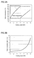
- Fig. 3A is a graph showing the relationship among a supply temperature, a return temperature, and a heating output when the control of the present embodiment is performed.
- Fig. 3B also is a graph showing the relationship between a water circulation rate and a heating output when the control of the present embodiment is performed. These graphs are derived from the heat radiation characteristics of a commercially available radiator.
- the heat pump heater 100 operates in the following manner. In the case where the heating output needs to be increased, the supply temperature is raised to increase the quantity of heat to be supplied to the radiator 109 and the water circulation rate is maintained almost constant by the inverter pump 108 to maintain the return temperature at the specific temperature (i.e., to prevent the return temperature from exceeding the specific temperature).
- the water circulation rate increases slowly as the heating output increases.
- the supply temperature is lowered to reduce the quantity of heat to be supplied to the radiator 109 and the water circulation rate is maintained almost constant by the inverter pump 108 to maintain the return temperature at the specific temperature.
- the water circulation rate decreases slowly as the heating output decreases.
- a high COP can be achieved by maintaining the return temperature at the specific temperature.
- the variations in the water circulation rate are relatively small.
- the difference between the supply temperature and the return temperature increases monotonically with an increase in the heating output.
- the difference between the supply temperature and the return temperature has a peak value at a certain heating output (6 kW in Fig. 3A ).
- the heat pump 101 and the inverter pump 108 are controlled so that the supply temperature and the return temperature have profiles shown in Fig. 3A .
- the maximum supply temperature When the maximum supply temperature is low, for example, 55°C, the maximum supply temperature drops to 55°C. Also when the maximum supply temperature is 55°C, the supply temperature, the return temperature, and the heating output show profiles similar to those shown in Fig. 3A and Fig. 3B .
- the inverter pump 108 is controlled based on the detection results of the first temperature sensor 111 and the second temperature sensor 112 to prevent the return temperature from rising with a rise in the supply temperature. With this control, a rise in the refrigerant temperature at the outlet of the radiator 103 of the heat pump 101 can be suppressed. Accordingly, the heat pump heater 100 can achieve a high COP even when the supply temperature is raised to increase the heating output.
- the inverter pump 108 is controlled based on the detection results of the first temperature sensor 111 and the second temperature sensor 112 to prevent the return temperature from dropping, more specifically to prevent the return temperature from dropping with a drop in the supply temperature.
- the return temperature can be maintained at a specific temperature even if the supply temperature drops.
- the water circulation rate can be maintained almost constant when the supply temperature is lower than the maximum supply temperature. In the example shown in Fig. 3B , when the supply temperature is lower than the maximum supply temperature, the water circulation rate is 0 to 1.2 liters per minute.
- the heat pump heater 100 when the supply temperature is equal to or higher than the maximum supply temperature, that is, in a range where the heating output is equal to or higher than 6 kW, the heat pump heater 100 operates in the following manner.
- the circulation rate is increased.
- the quantity of heat to be supplied to the radiator 109 can be increased while a rise in the supply temperature is prevented.
- the circulation rate is reduced.
- the quantity of heat to be supplied to the radiator 109 can be reduced while a drop in the supply temperature is prevented.
- the inverter pump 108 is controlled so that the water circulation rate is increased or decreased with an increase or a decrease in the heating output while the supply temperature is maintained at the maximum supply temperature.
- the controller 110 controls the inverter pump 108 to suppress a rise in the return temperature while maintaining the supply temperature at or below the maximum supply temperature. With this control, a rise in the refrigerant temperature at the outlet of the radiator 103 can be suppressed, and therefore the COP of the heat pump cycle is increased.
- the heat pump heater 100 of the present embodiment includes the inverter pump 108 as the flow regulator for changing the water circulation rate.
- the controller 110 increases or reduces the water circulation rate by adjusting the rotational speed of the inverter pump 108 and thereby increases or reduces the quantity of heat to be supplied to the radiator 109.
- the water circulation rate can be changed easily with a simple configuration for controlling the frequency of a power source to be supplied to the inverter pump 108. In the case where a low water circulation rate suffices, the power consumption of the inverter pump 108 can be sufficiently reduced.
- FIG. 4 is a configuration diagram of a heat pump heater according to a first modification.
- a heat pump heater 200 includes, as the flow regulator for changing the water circulation rate, a constant rate pump 117 and a flow control valve 114. Except for these, the first modification is the same as the embodiment described with reference to Fig. 1 to Fig. 3B .
- the controller 110 increases or reduces the water circulation rate in the heat transfer circuit 107 by adjusting the opening degree of the flow control valve 114 and thereby increases or reduces the quantity of heat to be supplied to the radiator 109. Specifically, in the case where the water circulation rate needs to be increased, the opening degree of the flow control valve 114 is increased. Then, the water pressure drops at the outlet of the pump 108, and a pressure rise in the pump 108 also decreases. As a result, the volumetric efficiency of the pump 108 is increased, and thus the discharge rate is increased. On the other hand, in the case where the water circulation rate needs to be reduced, the opening degree of the flow control valve 114 is reduced.
- the pump 108 always operates at a constant rotational speed (a rotational speed that is almost equal to the frequency of the power source). According to the first modification, the water circulation rate can be regulated with simple configuration and control. Furthermore, with the use of an inexpensive constant rate pump 117, a cost reduction can be expected.
- FIG. 5 is a configuration diagram of a heat pump heater according to a second modification.
- a heat pump heater 300 includes, as the flow regulator for changing the water circulation rate, a constant rate pump 117, a bypass circuit 115 and a bypass valve 116. Except for these, the second modification is the same as the embodiment described with reference to Fig. 1 to Fig. 3B .
- the bypass circuit 115 is connected to the heat transfer circuit 107 to bypass the constant rate pump 117.
- the bypass valve 116 is provided in the bypass circuit 115 to regulate the water flow rate in the bypass circuit 115.
- the controller 110 increases or reduces the water circulation rate in the heat transfer circuit 107 by adjusting the opening degree of the bypass valve 116 and thereby increases or reduces the quantity of heat to be supplied to the radiator 109. According to the second modification, the water circulation rate can be regulated with simple configuration and control. Furthermore, with the use of an inexpensive constant rate pump 117, a cost reduction can be expected.
- the heat pump heater 100 shown in Fig. 1 includes the first temperature sensor 111 for detecting the supply temperature. However, it is also possible to detect (more specifically, to estimate) the supply temperature by a method other than the method using the first temperature sensor 111. The method for detecting (or estimating) the supply temperature is not particularly limited.
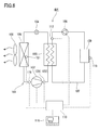
- FIG. 6 is a configuration diagram of a heat pump heater according to a third modification.
- a heat pump heater 401 includes a suction temperature sensor 119, a discharge temperature sensor 120, and an evaporation temperature sensor 121.
- the suction temperature sensor 119 detects the temperature (suction temperature) of a refrigerant drawn into the compressor 102.
- the discharge temperature sensor 120 detects the temperature (discharge temperature) of the refrigerant discharged from the compressor 102.
- the evaporation temperature sensor 121 detects the temperature (evaporation temperature) of the refrigerant in the evaporator 105. Except for these, the third modification is the same as the embodiment described with reference to Fig. 1 to Fig. 3B .
- the temperature of a refrigerant is maintained at approximately the condensation temperature Te in the radiator 103 (condenser).
- the water temperature is lowest at the inlet of the radiator 103 and highest at the outlet of the radiator 103.
- the water temperature never exceeds the refrigerant temperature. Since the quantity of heat of the refrigerant in a superheated state is relatively small, the water temperature at the outlet of the radiator 103, that is, the supply temperature shows a value close to the condensation temperature Te. Accordingly, the supply temperature can be estimated from the condensation temperature Te.
- the difference between the supply temperature and the condensation temperature Te depends on the specifications of the radiator 103, the type of refrigerant, the water circulation rate, etc. Typically, the supply temperature is higher than the condensation temperature Te by several degrees centigrade.
- the controller 110 may be configured to identify the supply temperature from the condensation temperature Te by using a reference table, in which the correspondence relationship between the condensation temperature Te and the supply temperature is described, or an arithmetic expression.
- the supply temperature can be estimated from the condensation temperature Te, which is estimated from the suction temperature, the discharge temperature and the evaporation temperature.
- the pressure (suction pressure) of a refrigerant drawn into the compressor 102 is estimated from the evaporation temperature.
- the degree of superheat of the refrigerant drawn into the compressor 102 is obtained from the suction temperature.
- the pressure (discharge pressure) of the refrigerant discharged from the compressor 102 is estimated from the state of the drawn refrigerant, the discharge temperature, and the known adiabatic efficiency of the compressor 102.
- the condensation temperature Te is estimated from the discharge pressure, and then the supply temperature is estimated.
- the condensation temperature Te can be estimated without using the discharge temperature and the evaporation temperature.
- the method for estimating the supply temperature should be selected appropriately according to the operation method of the heat pump 101.
- the expansion mechanism 104 expansion valve
- the above estimation method can be used.
- the condensation temperature Te cannot be estimated because the dryness of the refrigerant is unknown.
- a liquid refrigerant is injected into a working chamber of the compressor 102.
- it is possible to estimate the supply temperature by providing a temperature sensor for detecting the condensation temperature Te, as described later.
- the controller 110 may be configured to control the inverter pump 108 so that the temperature of the refrigerant discharged from the compressor 102 is maintained at an upper limit temperature when the temperature of the discharged refrigerant exceeds the upper limit temperature.
- the "upper limit temperature” depends on the heat resistance of the coating of a winding of a motor used in a compressor. When the temperature of the discharged refrigerant exceeds the upper limit temperature, the insulation of the winding may be destroyed, resulting in a short circuit of the motor. In addition, when the temperature of the discharged refrigerant rises too high, refrigerating machine oil may be degraded.
- the controller 110 controls the inverter pump 108 to increase the water circulation rate. With this control, the refrigerant in a high pressure vapor state in the radiator 103 can be cooled sufficiently.
- the high pressure of the heat pump cycle is equal to or lower than the critical pressure
- the critical pressure when the water circulation rate is increased, the liquefaction of the refrigerant is accelerated in the radiator 103.
- the high pressure of the heat pump cycle is equal to or higher than the critical pressure
- the high pressure of the heat pump cycle is equal to or higher than the critical pressure
- the high pressure of the heat pump cycle is equal to or higher than the critical pressure
- the pressure of the refrigerant discharged from the compressor 102 drops, the temperature of the discharged refrigerant also drops.
- the temperature of the discharged refrigerant is maintained at the upper limit temperature or drops below the upper limit temperature. With this control, the reliability of the heat pump heater 401 is enhanced.
- the present modification even when the heating output is increased, a rise in the return temperature can be suppressed while the supply temperature is maintained at or below the maximum supply temperature. Thereby, a rise in the refrigerant temperature at the outlet of the radiator 103 can be suppressed, and therefore the COP of the heat pump cycle is increased.
- the discharge pressure sensor 122 may be used instead of the discharge temperature sensor 120.
- the condensation temperature Te can be estimated from the discharge pressure.
- the supply temperature can be estimated from the condensation temperature Te.
- the controller 110 may be configured to control the inverter pump 108 so that the pressure of the refrigerant discharged from the compressor 102 is maintained at an upper limit pressure when the pressure of the discharged refrigerant exceeds the upper limit pressure. Specifically, when the pressure of the refrigerant discharged from the compressor 102 exceeds the upper limit pressure, the controller 110 controls the inverter pump 108 to increase the water circulation rate.
- the "upper limit pressure" is determined based on the withstand pressure of the least pressure resistant one (for example, the compressor 102 or the expansion valve 104) of the constituent components of the heat pump 101.
- a heat pump heater 402 includes a casing temperature sensor 123 for detecting the temperature of the closed casing of the compressor 102.
- the controller 110 may be configured to control the inverter pump 108 so that the temperature of the closed casing of the compressor 102 is maintained at an upper limit temperature when the temperature of the closed casing exceeds the upper limit temperature. Specifically, when the temperature of the closed casing of the compressor 102 exceeds the upper limit temperature, the controller 110 controls the inverter pump 108 to increase the water circulation rate.
- the temperature of the discharged refrigerant is maintained at the upper limit temperature or drops below the upper limit temperature, and thus the temperature of the closed casing also is maintained at the upper limit temperature or drops below the upper limit temperature.
- the reliability of the heat pump heater 402 is enhanced.
- the temperature sensors other than the casing temperature sensor 123 can be provided on the outer peripheral surface of refrigerant pipes or the outer peripheral surface of pipes.
- the casing temperature sensor 123 can be provided on the outer peripheral surface of the closed casing of the compressor 102.
- the casing temperature sensor 123 may be provided on the upper part of the closed casing.
- the heat capacity of the closed casing is larger than that of the discharge pipe of the compressor 102.
- the temperature of the closed casing is almost equal to that of the refrigerant discharged from the compressor 102, if the responsiveness is ignored.
- a heat pump heater 403 includes a condensation temperature sensor 125 for detecting the condensation temperature Te of the refrigerant in the radiator 103 (condenser). As described in the third modification, the supply temperature can be estimated from the condensation temperature Te.
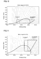
- the cycle obtained when the control of the present invention was performed was calculated by computer simulation.
- the cycle obtained when the control described in JP 2001-124349 A was performed was calculated.
- the conditions used in the calculations are as follows.
- Fig. 10 shows the calculation results obtained when R410A was used
- Fig. 11 shows those obtained when CO 2 was used.
- the control of the present invention that is, the control to prevent the return temperature from rising with a rise in the supply temperature
- the difference between the enthalpy at the inlet of the radiator and that at the outlet of the radiator increases.
- the COP of the cycle shown in Example 1 was 3.45.
- the COP of the cycle shown in Example 2 was 1.89.
- the COP of the cycle shown in Comparative Example 1 was 3.19.
- the COP of the cycle shown in Comparative Example 2 was 1.37.
- the heat pump heater of the present invention is useful as a hot water circulation type radiator heater, a hot water circulation type fan coil heater, etc.
Landscapes
- Engineering & Computer Science (AREA)
- Physics & Mathematics (AREA)
- Mechanical Engineering (AREA)
- Thermal Sciences (AREA)
- General Engineering & Computer Science (AREA)
- Chemical & Material Sciences (AREA)
- Combustion & Propulsion (AREA)
- Fluid Mechanics (AREA)
- Steam Or Hot-Water Central Heating Systems (AREA)
- Heat-Pump Type And Storage Water Heaters (AREA)
- Air Conditioning Control Device (AREA)
Abstract
Description
- The present invention relates to a heat medium circulation type heater using a heat pump as a heat source.
- As a heat medium circulation type heater, a hot water heater using a heat pump as a heat source is known.
Fig. 12 is a configuration diagram of a hot water circulation type heat pump heater described inPatent Literature 1. Aheat pump heater 500 includes anoutdoor unit 501, a heat exchanger (condenser) 503, aradiator 505, apump 504, athermistor 507, and athermistor 508. Theradiator 505 is connected to theheat exchanger 503 by ahot water pipe 506. Thehot water pipe 506 is provided with thepump 504. Thethermistors - When the outside air temperature is high, the load on the
radiator 505 is small. Therefore, a compressor of theoutdoor unit 501 is controlled so that relatively low temperature hot water is supplied to theradiator 505 through thehot water pipe 506. With this control, a condensation temperature in the heat pump cycle can be reduced. When the condensation temperature drops, a difference between a condensation pressure and an evaporation pressure is reduced, and thus the compression work of the compressor is reduced. As a result, an input (power consumption) of theheat pump heater 500 is reduced, and the appliance efficiency (the coefficient of performance of the heat pump cycle) is enhanced. -
Patent Literature 1JP 2001-124349 A - On the other hand, when the load on the
radiator 505 increases, the compressor of theoutdoor unit 501 is controlled so that relatively high temperature hot water is supplied to theradiator 505 through thehot water pipe 506. Then, the temperature of hot water returned to the heat exchanger 503 (i.e., a return temperature) rises accordingly. Specifically, as shown inFig. 13 , the return temperature rises as the temperature of hot water to be supplied to the radiator 505 (i.e., a supply temperature) rises. - When the return temperature rises, the temperature of a refrigerant at the outlet of the
heat exchanger 503 rises, and thus the enthalpy h_out of the refrigerant increases. Therefore, a difference Δh (= h_in - h_out) between the enthalpy h_in of the refrigerant at the inlet of theheat exchanger 503 and the enthalpy h_out of the refrigerant at the outlet of theheat exchanger 503 is reduced. This means that the coefficient of performance of the heat pump cycle decreases. Thus, a conventional hot water circulation type heat pump heater has a problem that it becomes less efficient as the heating output is increased. In particular, a heat pump cycle operating at a pressure equal to or higher than the critical pressure has a problem that an enthalpy difference Δh decreases rapidly when the return temperature exceeds the critical temperature. - It is an object of the present invention to improve the efficiency of a heat medium circulation type heat pump heater.
- The present invention provides a heat medium circulation type heat pump heater including: a heat pump having a compressor, a radiator, an expansion mechanism, and an evaporator; a heat transfer circuit in which a heat medium heated by the heat pump circulates; a heat utilization device connected to the heat transfer circuit; a flow regulator provided in the heat transfer circuit to change a circulation rate of the heat medium; and a controller configured to control the heat pump to allow the heat utilization device to produce a required heating output, and to control the flow regulator to prevent a return temperature from rising with a rise in a supply temperature, the return temperature being a temperature of the heat medium returned from the heat transfer circuit to the heat pump, and the supply temperature being a temperature of the heat medium heated by the heat pump and fed to the heat transfer circuit.
- According to the present invention, the flow regulator is controlled to prevent the return temperature from rising with a rise in the supply temperature. With this control, a rise in the refrigerant temperature at the outlet of the radiator can be suppressed even if the supply temperature rises. Accordingly, the heat pump heater of the present invention can achieve a high coefficient of performance (COP) even when the supply temperature is raised to increase a heating output.
-
-
Fig. 1 is a configuration diagram of a hot water circulation type heat pump heater in an embodiment of the present invention. -
Fig. 2 is a control flow chart of a normal operation of the heat pump heater shown inFig. 1 . -
Fig. 3A is a graph showing the relationship among a supply temperature, a return temperature, and a heating output. -
Fig. 3B is a graph showing the relationship between a water circulation rate and a heating output. -
Fig. 4 is a configuration diagram of a hot water circulation type heat pump heater according to a first modification. -
Fig. 5 is a configuration diagram of a hot water circulation type heat pump heater according to a second modification. -
Fig. 6 is a configuration diagram of a hot water circulation type heat pump heater according to a third modification. -
Fig. 7 is a correlation diagram of a refrigerant temperature and a water temperature in a condenser. -
Fig. 8 is a configuration diagram of a hot water circulation type heat pump heater according to a fourth modification. -
Fig. 9 is a configuration diagram of a hot water circulation type heat pump heater according to a fifth modification. -
Fig. 10 shows Mollier diagrams obtained when a control of the present invention and a conventional control are performed in a heat pump heater using R410A as a refrigerant. -
Fig. 11 shows Mollier diagrams obtained when a control of the present invention and a conventional control are performed in a heat pump heater using CO2 as a refrigerant. -
Fig. 12 is a configuration diagram of a conventional hot water circulation type heat pump heater. -
Fig. 13 is a graph showing the relationship between a heating output and water temperatures in a conventional heat pump heater. - Hereinafter, embodiments of the present invention will be described with reference to the drawings. The present invention is not limited by the following embodiments.
- As shown in
Fig. 1 , aheat pump heater 100 of the present embodiment includes aheat pump 101, aheat transfer circuit 107, aninverter pump 108, aradiator 109, acontroller 110, afirst temperature sensor 111, and asecond temperature sensor 112. A heat medium in theheat transfer circuit 107 is heated by theheat pump 101, and the heated heat medium is supplied to theradiator 109 as a heat utilization device. Thereby, a heating effect is exerted around theradiator 109. The heat medium releases heat in theradiator 109, and then is heated again in theheat pump 101. That is, theheat pump heater 100 is configured as a heat medium circulation type heat pump heater. The heat medium is typically water, and other fluids such as oil also can be used. - The
heat pump 101 has acompressor 102, a radiator 103 (condenser), anexpansion mechanism 104, and anevaporator 105. These components are connected in series in this order by refrigerant pipes to form a refrigerant circuit. Thecompressor 102 is typically a positive displacement compressor. Examples of positive displacement compressors include a rotary compressor, a scroll compressor, a screw compressor, etc. Theradiator 103 is typically constituted by a water-refrigerant heat exchanger. In theradiator 103, heat is exchanged between a refrigerant in the refrigerant circuit and water in theheat transfer circuit 107, so that the heat of the refrigerant is fed to the water. Theevaporator 105 is typically constituted by an air-refrigerant heat exchanger. Theevaporator 105 is provided with afan 106 for promoting heat exchange between the refrigerant and air. Theexpansion mechanism 104 is typically an expansion valve, and may be constituted by a positive displacement expander capable of recovering power from the refrigerant. - The refrigerant circuit of the
heat pump 101 is filled with a refrigerant such as a fluorine-containing refrigerant, a supercritical refrigerant, or the like. Examples of the fluorine-containing refrigerant include R22, R32, R410A, R407C, R134a, R1234yf, etc. An example of the supercritical refrigerant is carbon dioxide. In the case where relatively low temperature (for example, 55°C or lower) hot water is supplied to theradiator 109, fluorine-containing refrigerants such as R410A and R22 can be suitably used. When the temperature of the hot water is low, the condensation pressure of the refrigerant can be reduced. This is effective in reducing the compression work of thecompressor 102. - In the case where relatively high temperature (for example, 90°C or lower, or 75°C or lower) hot water is supplied to the
radiator 109, a cycle using carbon dioxide, a cycle using R407C, a cascade cycle of a low temperature cycle using R410A and a high temperature cycle using R134a, or a cascade cycle of a low temperature cycle using R32 and a high temperature cycle using R1234yf can be employed. The cycle using carbon dioxide has various advantages such as a low GWP (Global Warming Potential), ease of producing high temperature hot water, and no need of refrigerant recovery at the time of disposal of a system. - The
heat transfer circuit 107 is typically constituted by pipes. Water (hot water) heated in theradiator 103 of theheat pump 101 circulates through theheat transfer circuit 107. Theinverter pump 108 is provided in theheat transfer circuit 107, and serves as a flow regulator for changing the circulation rate of the water. The "circulation rate" indicates the flow rate of water passing through theradiator 109 per unit time. Theradiator 109 is connected to theheat transfer circuit 107 to heat a room. Examples of theradiator 109 include a room-mounted heat exchanger, a floorboard with a built-in heat radiation pipe, etc. - The
controller 110 controls the rotational speed of theinverter pump 108 to change the circulation rate of water. Thecontroller 110 also controls the heat pump 100 (thecompressor 102, theexpansion mechanism 104 and the fan 106) so that a required heating output is produced in theradiator 109. As thecontroller 110, a DSP (Digital Signal Processor) including an A/D conversion circuit, an input/output circuit, an arithmetic circuit, a memory device, etc. can be used. A program for controlling theinverter pump 108 and theheat pump 101 is stored in thecontroller 110. Furthermore, anoperation unit 118 for receiving an input from a user is connected to thecontroller 110. Theoperation unit 118 includes an operation start switch, an operation mode selector, a room temperature selector, etc. A preset temperature (target room temperature) input with the room temperature selector of theoperation unit 118 is stored in thecontroller 110. A required heating output can be determined based on a difference between a current room temperature and a preset temperature. An outside air temperature is sometimes considered to determine the required heating output. The "heating output" means the heating capability of theradiator 109. - The first temperature sensor 111 (supply temperature sensor) detects a supply temperature, which is the temperature of water heated by the
heat pump 101 and fed to theheat transfer circuit 107, and outputs a signal corresponding to the detected supply temperature. The supply temperature is the temperature of the water before releasing heat in theradiator 109. The second temperature sensor 112 (return temperature sensor) detects a return temperature, which is the temperature of the water returned from theheat transfer circuit 107 to theheat pump 101, and outputs a signal corresponding to the detected return temperature. The return temperature is the temperature of the water after releasing heat in theradiator 109. A third temperature sensor 113 (ambient temperature sensor) for detecting the ambient temperature of theradiator 109 is provided. The "ambient temperature" is, to be precise, a room temperature. Thetemperature sensors temperature sensors controller 110 to transmit output signals to thecontroller 110. This also applies to some modifications described later. -
Fig. 2 is a control flow chart of a normal operation of the heat pump heater shown inFig. 1 . Each process shown inFig. 2 can be performed on a regular basis by thecontroller 110. - When the operation start switch of the
operation unit 118 is turned on, the following initial operation may be performed before the normal operation shown inFig. 2 . First, when the operation start switch is turned on, an appropriate initial heating output is determined based on a room temperature, an outside air temperature, and a preset temperature at that time. Then, the rotational speed of thecompressor 102, in other words, the heat supply capability of theheat pump 101 is determined so that the determined initial heating output is produced in theradiator 109. When a given time has elapsed from the start of the operation or the room temperature has reached the preset temperature, the heater enters into the normal operation. - As shown in
Fig. 2 , in Step S11, an output signal of thethird temperature sensor 113 is obtained, and the room temperature is identified by the output signal of thethird temperature sensor 113. Next, theheat pump 101 is controlled so that a required heating output is produced in theradiator 109. Specifically, in Step S12, whether or not the room temperature is lower than the preset temperature is determined. When the room temperature is lower than the preset temperature, the rotational speed of thecompressor 102 is increased to increase the heating output (Step S13). When the room temperature is equal to or higher than the preset temperature, the rotational speed of thecompressor 102 is reduced to reduce the heating output (Step S14). - When the rotational speed of the
compressor 102 is increased, the refrigerant circulation rate in theheat pump 101 increases. As a result, both the heat absorbing capability of theevaporator 105 and the heating capability of theradiator 103 increase. When the heating capability of theradiator 103 increases, the supply temperature and the return temperature rise in theheat transfer circuit 107. When the rotational speed of thecompressor 102 is reduced, the refrigerant circulation rate in theheat pump 101 decreases. As a result, both the heat absorbing capability of theevaporator 105 and the heating capability of theradiator 103 decrease. When the heating capability of theradiator 103 decreases, the supply temperature and the return temperature drop in theheat transfer circuit 107. - The
operation unit 118 may be provided with a heating output selector so that a user can set an arbitrary heating output. Also in this case, theheat pump 101 is controlled so that the heating output set by the user can be produced. - Next, in Step S15, an output signal of the
first temperature sensor 111 and an output signal of thesecond temperature sensor 122 are obtained. The supply temperature is identified by the output signal of thefirst temperature sensor 111. In Step S16, whether or not the supply temperature is lower than a predetermined maximum supply temperature is determined. - As stated herein, the "maximum supply temperature" is a temperature determined based on the type of the refrigerant used for the
heat pump 101, the type of the heat medium used for theheat transfer circuit 107, the specifications of theheat pump heater 100, etc. For example, when the refrigerant is carbon dioxide and the heat medium is water, the maximum supply temperature can be set to 90°C. Theinverter pump 108 is controlled so that the supply temperature is maintained at 90°C or lower even if any heating output is requested. - When the supply temperature is lower than the maximum supply temperature, the return temperature is identified by the previously obtained output signal of the
second temperature sensor 112. Then, theinverter pump 108 is controlled so that the return temperature approaches (preferably, coincides with) a specific temperature determined based on the detection result of thethird temperature sensor 113. - In view of the efficiency of the
heat pump 101, a low return temperature is preferred. However, the return temperature cannot be reduced to the room temperature even if any control is performed. Therefore, an ideal return temperature in a range that can be achieved relatively easily by the control of theinverter pump 108 can be determined as a "specific temperature". In the present embodiment, a temperature obtained by adding a predetermined temperature difference ΔT to a room temperature is regarded as a "specific temperature". The predetermined temperature difference ΔT may be, for example, a constant value within the range of 1 to 5°C, or a value determined to correspond to a room temperature on a one-to-one basis. - In Step S17, whether or not the return temperature is higher than the specific temperature (= room temperature + ΔT) is determined. When the return temperature is higher than the specific temperature, the rotational speed of the
inverter pump 108 is reduced to reduce the water circulation rate (Step S18). When the water circulation rate is reduced, the quantity of heat that a unit volume of water loses in theradiator 109 increases, and thus the return temperature drops. When the water circulation rate decreases and the return temperature drops, the quantity of heat that a unit volume of water receives from the refrigerant in theradiator 103 of theheat pump 101 increases. As a result, the supply temperature rises. - On the other hand, when the return temperature is equal to or lower than the specific temperature, the rotational speed of the
inverter pump 108 is increased to increase the water circulation rate (Step S19). When the water circulation rate is increased, the quantity of heat that a unit volume of water loses in theradiator 109 decreases, and thus the return temperature rises. When the water circulation rate increases and the return temperature rises, the quantity of heat that a unit volume of water receives from the refrigerant in theradiator 103 of theheat pump 101 decreases. As a result, the supply temperature drops. - As shown in Steps S16 to S19, when the supply temperature is lower than the maximum supply temperature, a rise in the return temperature is prevented by controlling the
inverter pump 108 so as to reduce the water circulation rate. A drop in the return temperature is prevented by controlling theinverter pump 108 so as to increase the water circulation rate. As a result, the return temperature is maintained at about the specific temperature (= room temperature + ΔT). A high COP can be achieved by maintaining the return temperature at the specific temperature. Furthermore, the variations in the water circulation rate are relatively small. - Since a low return temperature is favorable for the efficiency of the
heat pump 101,Step S 19 seems to be a useless process. However, if only the processes of Steps S17 and S18 are performed to lower the return temperature, the water circulation rate may be insufficient. If the water circulation rate is insufficient, the rotational speed of thecompressor 102 may need to be increased significantly to raise the supply temperature excessively in order to obtain a required heating output, or the required heating output may not be obtained. In contrast, the addition of the process of Step S19 makes it possible to keep the water circulation rate almost constant when the supply temperature is lower than the maximum supply temperature. That is, it is possible to balance the rotational speed of thecompressor 102 of theheat pump 101 and the rotational speed of theinverter pump 108 so that theheat pump 101 can be operated efficiently and that the required heating output can be obtained. - On the other hand, after the supply temperature reaches the maximum supply temperature as a result of an increase in the heating output, the following control is performed. That is, when the supply temperature is equal to or higher than the maximum supply temperature, the
inverter pump 108 is controlled to maintain the supply temperature at the maximum supply temperature. The upper limit of the supply temperature is determined by the constraints such as the specifications of theheat pump 101, the type of the heat medium, etc. In the case where the heat medium is water, for example, the water should not be heated to a temperature higher than 90°C in view of safety. In the case where the refrigerant is R410A, for example, the temperature of the heat medium should be maintained up to about 55°C, from the viewpoints of the efficiency of the cycle and the physical properties of R410A. The reliability of theheat pump heater 100 can be ensured and theheat pump heater 100 can be operated at a high efficiency by maintaining the supply temperature at the maximum supply temperature. - Specifically, in Step S16, whether or not the supply temperature is lower than a predetermined maximum supply temperature is determined. When the supply temperature is equal to or higher than the maximum supply temperature, the rotational speed of the
inverter pump 108 is increased in Step S19 to increase the water circulation rate. When the water circulation rate is increased, the quantity of heat that a unit volume of water loses in theradiator 109 decreases, and thus the return temperature rises. When the water circulation rate increases and the return temperature rises, the quantity of heat that a unit volume of water receives from the refrigerant in theradiator 103 of theheat pump 101 decreases. As a result, the supply temperature drops. - The "preset temperature" in Step S12 may be a temperature range with a constant width (for example, a preset temperature 0.5°C). When the room temperature falls within the predetermined temperature range, the rotational speed of the
compressor 102 can be maintained to keep the heating output at that time. This eliminates the need to adjust the rotational speed of theinverter pump 108 frequently. Likewise, the "maximum supply temperature" in Step S16 and the "specific temperature" in Step S18 may each be a temperature range with a constant width. - That is, the
controller 110 may be configured to control the inverter pump 108 (flow regulator) so that a difference between a return temperature and a specific temperature that is determined based on the ambient temperature of theradiator 109 falls within a predetermined range of temperature differences. Such a configuration is considered to be essentially equivalent to a control for bringing the return temperature closer to the specific temperature. The "predetermined range of temperature differences" can be set to a value enough to prevent hunting. For example, it is ± 2°C. -
Fig. 3A is a graph showing the relationship among a supply temperature, a return temperature, and a heating output when the control of the present embodiment is performed.Fig. 3B also is a graph showing the relationship between a water circulation rate and a heating output when the control of the present embodiment is performed. These graphs are derived from the heat radiation characteristics of a commercially available radiator. - In an example shown in
Fig. 3A and Fig. 3B , the maximum supply temperature is 90°C and the specific temperature (= room temperature + ΔT) is 20°C. When the supply temperature is lower than the maximum supply temperature, that is, in a range where the heating output is less than a predetermined value (less than 6 kW in the example shown inFig. 3A and Fig. 3B ), theheat pump heater 100 operates in the following manner. In the case where the heating output needs to be increased, the supply temperature is raised to increase the quantity of heat to be supplied to theradiator 109 and the water circulation rate is maintained almost constant by theinverter pump 108 to maintain the return temperature at the specific temperature (i.e., to prevent the return temperature from exceeding the specific temperature). To be precise, the water circulation rate increases slowly as the heating output increases. In the case where the heating output needs to be reduced, the supply temperature is lowered to reduce the quantity of heat to be supplied to theradiator 109 and the water circulation rate is maintained almost constant by theinverter pump 108 to maintain the return temperature at the specific temperature. To be precise, the water circulation rate decreases slowly as the heating output decreases. A high COP can be achieved by maintaining the return temperature at the specific temperature. Furthermore, the variations in the water circulation rate are relatively small. - With the conventional control, as shown in
Fig. 13 , the difference between the supply temperature and the return temperature increases monotonically with an increase in the heating output. In contrast, with the control of the present embodiment, as shown inFig. 3A , the difference between the supply temperature and the return temperature has a peak value at a certain heating output (6 kW inFig. 3A ). Theheat pump 101 and theinverter pump 108 are controlled so that the supply temperature and the return temperature have profiles shown inFig. 3A . - When the maximum supply temperature is low, for example, 55°C, the maximum supply temperature drops to 55°C. Also when the maximum supply temperature is 55°C, the supply temperature, the return temperature, and the heating output show profiles similar to those shown in
Fig. 3A and Fig. 3B . - As described above, when the supply temperature is lower than the maximum supply temperature, the
inverter pump 108 is controlled based on the detection results of thefirst temperature sensor 111 and thesecond temperature sensor 112 to prevent the return temperature from rising with a rise in the supply temperature. With this control, a rise in the refrigerant temperature at the outlet of theradiator 103 of theheat pump 101 can be suppressed. Accordingly, theheat pump heater 100 can achieve a high COP even when the supply temperature is raised to increase the heating output. - Likewise, the
inverter pump 108 is controlled based on the detection results of thefirst temperature sensor 111 and thesecond temperature sensor 112 to prevent the return temperature from dropping, more specifically to prevent the return temperature from dropping with a drop in the supply temperature. With this control, the return temperature can be maintained at a specific temperature even if the supply temperature drops. Furthermore, the water circulation rate can be maintained almost constant when the supply temperature is lower than the maximum supply temperature. In the example shown inFig. 3B , when the supply temperature is lower than the maximum supply temperature, the water circulation rate is 0 to 1.2 liters per minute. - As shown in
Fig. 3A and Fig. 3B , when the supply temperature is equal to or higher than the maximum supply temperature, that is, in a range where the heating output is equal to or higher than 6 kW, theheat pump heater 100 operates in the following manner. In the case where the heating output needs to be increased, the circulation rate is increased. Thereby, the quantity of heat to be supplied to theradiator 109 can be increased while a rise in the supply temperature is prevented. In the case where the heating output needs to be reduced, the circulation rate is reduced. Thereby, the quantity of heat to be supplied to theradiator 109 can be reduced while a drop in the supply temperature is prevented. More specifically theinverter pump 108 is controlled so that the water circulation rate is increased or decreased with an increase or a decrease in the heating output while the supply temperature is maintained at the maximum supply temperature. - As described above, according to the present embodiment, even when the heating output is increased, the
controller 110 controls theinverter pump 108 to suppress a rise in the return temperature while maintaining the supply temperature at or below the maximum supply temperature. With this control, a rise in the refrigerant temperature at the outlet of theradiator 103 can be suppressed, and therefore the COP of the heat pump cycle is increased. - The
heat pump heater 100 of the present embodiment includes theinverter pump 108 as the flow regulator for changing the water circulation rate. Thecontroller 110 increases or reduces the water circulation rate by adjusting the rotational speed of theinverter pump 108 and thereby increases or reduces the quantity of heat to be supplied to theradiator 109. The water circulation rate can be changed easily with a simple configuration for controlling the frequency of a power source to be supplied to theinverter pump 108. In the case where a low water circulation rate suffices, the power consumption of theinverter pump 108 can be sufficiently reduced. -
Fig. 4 is a configuration diagram of a heat pump heater according to a first modification. Aheat pump heater 200 includes, as the flow regulator for changing the water circulation rate, aconstant rate pump 117 and aflow control valve 114. Except for these, the first modification is the same as the embodiment described with reference toFig. 1 to Fig. 3B . - The
controller 110 increases or reduces the water circulation rate in theheat transfer circuit 107 by adjusting the opening degree of theflow control valve 114 and thereby increases or reduces the quantity of heat to be supplied to theradiator 109. Specifically, in the case where the water circulation rate needs to be increased, the opening degree of theflow control valve 114 is increased. Then, the water pressure drops at the outlet of thepump 108, and a pressure rise in thepump 108 also decreases. As a result, the volumetric efficiency of thepump 108 is increased, and thus the discharge rate is increased. On the other hand, in the case where the water circulation rate needs to be reduced, the opening degree of theflow control valve 114 is reduced. Then, the water pressure rises at the outlet of thepump 108, and a pressure rise in thepump 108 also increases. As a result, the volumetric efficiency of thepump 108 is decreased, and thus the discharge rate is decreased. Thepump 108 always operates at a constant rotational speed (a rotational speed that is almost equal to the frequency of the power source). According to the first modification, the water circulation rate can be regulated with simple configuration and control. Furthermore, with the use of an inexpensiveconstant rate pump 117, a cost reduction can be expected. -
Fig. 5 is a configuration diagram of a heat pump heater according to a second modification. Aheat pump heater 300 includes, as the flow regulator for changing the water circulation rate, aconstant rate pump 117, abypass circuit 115 and abypass valve 116. Except for these, the second modification is the same as the embodiment described with reference toFig. 1 to Fig. 3B . - The
bypass circuit 115 is connected to theheat transfer circuit 107 to bypass theconstant rate pump 117. Thebypass valve 116 is provided in thebypass circuit 115 to regulate the water flow rate in thebypass circuit 115. Thecontroller 110 increases or reduces the water circulation rate in theheat transfer circuit 107 by adjusting the opening degree of thebypass valve 116 and thereby increases or reduces the quantity of heat to be supplied to theradiator 109. According to the second modification, the water circulation rate can be regulated with simple configuration and control. Furthermore, with the use of an inexpensiveconstant rate pump 117, a cost reduction can be expected. - The
heat pump heater 100 shown inFig. 1 includes thefirst temperature sensor 111 for detecting the supply temperature. However, it is also possible to detect (more specifically, to estimate) the supply temperature by a method other than the method using thefirst temperature sensor 111. The method for detecting (or estimating) the supply temperature is not particularly limited. -
Fig. 6 is a configuration diagram of a heat pump heater according to a third modification. Aheat pump heater 401 includes asuction temperature sensor 119, adischarge temperature sensor 120, and anevaporation temperature sensor 121. Thesuction temperature sensor 119 detects the temperature (suction temperature) of a refrigerant drawn into thecompressor 102. Thedischarge temperature sensor 120 detects the temperature (discharge temperature) of the refrigerant discharged from thecompressor 102. Theevaporation temperature sensor 121 detects the temperature (evaporation temperature) of the refrigerant in theevaporator 105. Except for these, the third modification is the same as the embodiment described with reference toFig. 1 to Fig. 3B . - As shown in
Fig. 7 , in the case where theheat pump 101 operates at or below the critical pressure, the temperature of a refrigerant is maintained at approximately the condensation temperature Te in the radiator 103 (condenser). The water temperature is lowest at the inlet of theradiator 103 and highest at the outlet of theradiator 103. However, the water temperature never exceeds the refrigerant temperature. Since the quantity of heat of the refrigerant in a superheated state is relatively small, the water temperature at the outlet of theradiator 103, that is, the supply temperature shows a value close to the condensation temperature Te. Accordingly, the supply temperature can be estimated from the condensation temperature Te. - The difference between the supply temperature and the condensation temperature Te depends on the specifications of the
radiator 103, the type of refrigerant, the water circulation rate, etc. Typically, the supply temperature is higher than the condensation temperature Te by several degrees centigrade. Thecontroller 110 may be configured to identify the supply temperature from the condensation temperature Te by using a reference table, in which the correspondence relationship between the condensation temperature Te and the supply temperature is described, or an arithmetic expression. - According to the
heat pump heater 401, the supply temperature can be estimated from the condensation temperature Te, which is estimated from the suction temperature, the discharge temperature and the evaporation temperature. Specifically, the pressure (suction pressure) of a refrigerant drawn into thecompressor 102 is estimated from the evaporation temperature. The degree of superheat of the refrigerant drawn into thecompressor 102 is obtained from the suction temperature. Thus, the state (the pressure and the degree of superheat) of the refrigerant drawn into thecompressor 102 is identified. The pressure (discharge pressure) of the refrigerant discharged from thecompressor 102 is estimated from the state of the drawn refrigerant, the discharge temperature, and the known adiabatic efficiency of thecompressor 102. The condensation temperature Te is estimated from the discharge pressure, and then the supply temperature is estimated. When adischarge pressure sensor 122 for detecting the discharge pressure of thecompressor 102 is used, the condensation temperature Te can be estimated without using the discharge temperature and the evaporation temperature. - The method for estimating the supply temperature should be selected appropriately according to the operation method of the
heat pump 101. In the case where the expansion mechanism 104 (expansion valve) is controlled so that the refrigerant drawn into thecompressor 102 is always in a superheated state, the above estimation method can be used. On the other hand, in the case where theexpansion mechanism 104 is controlled so that the refrigerant drawn into thecompressor 102 is in a gas-liquid two phase state to suppress the discharge temperature of thecompressor 102, the condensation temperature Te cannot be estimated because the dryness of the refrigerant is unknown. The same is true in the case where a liquid refrigerant is injected into a working chamber of thecompressor 102. In such a case, it is possible to estimate the supply temperature by providing a temperature sensor for detecting the condensation temperature Te, as described later. - Furthermore, the
controller 110 may be configured to control theinverter pump 108 so that the temperature of the refrigerant discharged from thecompressor 102 is maintained at an upper limit temperature when the temperature of the discharged refrigerant exceeds the upper limit temperature. Generally, the "upper limit temperature" depends on the heat resistance of the coating of a winding of a motor used in a compressor. When the temperature of the discharged refrigerant exceeds the upper limit temperature, the insulation of the winding may be destroyed, resulting in a short circuit of the motor. In addition, when the temperature of the discharged refrigerant rises too high, refrigerating machine oil may be degraded. - In the present modification, when the temperature of the discharged refrigerant exceeds the upper limit temperature, the
controller 110 controls theinverter pump 108 to increase the water circulation rate. With this control, the refrigerant in a high pressure vapor state in theradiator 103 can be cooled sufficiently. In the case where the high pressure of the heat pump cycle is equal to or lower than the critical pressure, when the water circulation rate is increased, the liquefaction of the refrigerant is accelerated in theradiator 103. In the case where the high pressure of the heat pump cycle is equal to or higher than the critical pressure, when the water circulation rate is increased, the density of the refrigerant is increased, and thus the refrigerant is brought into an almost liquid phase. Then, the pressure of the refrigerant in the radiator 103 (= the pressure of the refrigerant discharged from the compressor 102) drops. When the pressure of the refrigerant discharged from thecompressor 102 drops, the temperature of the discharged refrigerant also drops. As a result, the temperature of the discharged refrigerant is maintained at the upper limit temperature or drops below the upper limit temperature. With this control, the reliability of theheat pump heater 401 is enhanced. - According to the present modification, even when the heating output is increased, a rise in the return temperature can be suppressed while the supply temperature is maintained at or below the maximum supply temperature. Thereby, a rise in the refrigerant temperature at the outlet of the
radiator 103 can be suppressed, and therefore the COP of the heat pump cycle is increased. - As shown in
Fig. 6 , thedischarge pressure sensor 122 may be used instead of thedischarge temperature sensor 120. As described above, the condensation temperature Te can be estimated from the discharge pressure. The supply temperature can be estimated from the condensation temperature Te. Furthermore, thecontroller 110 may be configured to control theinverter pump 108 so that the pressure of the refrigerant discharged from thecompressor 102 is maintained at an upper limit pressure when the pressure of the discharged refrigerant exceeds the upper limit pressure. Specifically, when the pressure of the refrigerant discharged from thecompressor 102 exceeds the upper limit pressure, thecontroller 110 controls theinverter pump 108 to increase the water circulation rate. With this control, the pressure of the discharged refrigerant is maintained at the upper limit pressure or drops below the upper limit pressure, and therefore the temperature of the discharged refrigerant also is maintained at the upper limit temperature or drops below the upper limit temperature. As a result, the reliability of theheat pump heater 401 is enhanced. The "upper limit pressure" is determined based on the withstand pressure of the least pressure resistant one (for example, thecompressor 102 or the expansion valve 104) of the constituent components of theheat pump 101. - As shown in
Fig. 8 , aheat pump heater 402 according to a fourth modification includes acasing temperature sensor 123 for detecting the temperature of the closed casing of thecompressor 102. Thecontroller 110 may be configured to control theinverter pump 108 so that the temperature of the closed casing of thecompressor 102 is maintained at an upper limit temperature when the temperature of the closed casing exceeds the upper limit temperature. Specifically, when the temperature of the closed casing of thecompressor 102 exceeds the upper limit temperature, thecontroller 110 controls theinverter pump 108 to increase the water circulation rate. With this control, based on the theory described in the third modification, the temperature of the discharged refrigerant is maintained at the upper limit temperature or drops below the upper limit temperature, and thus the temperature of the closed casing also is maintained at the upper limit temperature or drops below the upper limit temperature. As a result, the reliability of theheat pump heater 402 is enhanced. - In the present description, the temperature sensors other than the
casing temperature sensor 123 can be provided on the outer peripheral surface of refrigerant pipes or the outer peripheral surface of pipes. In contrast, thecasing temperature sensor 123 can be provided on the outer peripheral surface of the closed casing of thecompressor 102. Specifically, thecasing temperature sensor 123 may be provided on the upper part of the closed casing. The heat capacity of the closed casing is larger than that of the discharge pipe of thecompressor 102. The temperature of the closed casing is almost equal to that of the refrigerant discharged from thecompressor 102, if the responsiveness is ignored. - As shown in
Fig. 9 , aheat pump heater 403 according to a fifth modification includes acondensation temperature sensor 125 for detecting the condensation temperature Te of the refrigerant in the radiator 103 (condenser). As described in the third modification, the supply temperature can be estimated from the condensation temperature Te. - The cycle obtained when the control of the present invention was performed was calculated by computer simulation. As a comparative example, the cycle obtained when the control described in
JP 2001-124349 A -
- Refrigerant R410A
- Minimum outside air temperature: -12°C
- Heating start temperature: 18°C
- Maximum heating output: 12 kW
- Supply temperature at maximum heating output: 55°C
- Return temperature at maximum heating output: 45°C
- Outside air temperature at calculation: -5°C
- Heating output at calculation: 9.2 kW
-
- Supply temperature: 55.0°C
- Return temperature: 34.0°C
-
- Supply temperature: 48.3°C
- Return temperature: 40.7°C
-
- Minimum outside air temperature: -12°C
- Heating start temperature: 18°C
- Maximum heating output: 12 kW
- Supply temperature at maximum heating output: 90°C
- Return temperature at maximum heating output: 70°C
- Outside air temperature at calculation: -5°C
- Heating output at calculation: 9.2 kW
-
- Supply temperature: 90.0°C
- Return temperature: 48.0°C
-
- Supply temperature: 76.7°C
- Return temperature: 61.3°C
-
Fig. 10 shows the calculation results obtained when R410A was used, andFig. 11 shows those obtained when CO2 was used. As shown inFig. 10 and Fig. 11 , when the control of the present invention, that is, the control to prevent the return temperature from rising with a rise in the supply temperature is performed, the difference between the enthalpy at the inlet of the radiator and that at the outlet of the radiator increases. Specifically, the COP of the cycle shown in Example 1 was 3.45. The COP of the cycle shown in Example 2 was 1.89. In contrast, the COP of the cycle shown in Comparative Example 1 was 3.19. The COP of the cycle shown in Comparative Example 2 was 1.37. - The heat pump heater of the present invention is useful as a hot water circulation type radiator heater, a hot water circulation type fan coil heater, etc.
Claims (11)
- A heat medium circulation type heat pump heater comprising:a heat pump having a compressor, a radiator, an expansion mechanism, and an evaporator;a heat transfer circuit in which a heat medium heated by the heat pump circulates;a heat utilization device connected to the heat transfer circuit;a flow regulator provided in the heat transfer circuit to change a circulation rate of the heat medium; anda controller configured to control the heat pump to allow the heat utilization device to produce a required heating output, and to control the flow regulator to prevent a return temperature from rising with a rise in a supply temperature, the return temperature being a temperature of the heat medium returned from the heat transfer circuit to the heat pump, and the supply temperature being a temperature of the heat medium heated by the heat pump and fed to the heat transfer circuit.
- The heat medium circulation type heat pump heater according to claim 1, wherein the controller controls the flow regulator so that a difference between the return temperature and a specific temperature falls within a predetermined range of temperature differences, the specific temperature being determined based on an ambient temperature of the heat utilization device.
- The heat medium circulation type heat pump heater according to claim 1 or 2, wherein when the supply temperature is lower than a predetermined maximum supply temperature, the controller prevents a rise in the return temperature by controlling the flow regulator so as to reduce the circulation rate.
- The heat medium circulation type heat pump heater according to claim 1 or 2, wherein when the supply temperature is lower than a predetermined maximum supply temperature, the controller prevents a drop in the return temperature by controlling the flow regulator so as to increase the circulation rate.
- The heat medium circulation type heat pump heater according to any one of claims 1 to 4, wherein when the supply temperature is equal to or higher than a predetermined maximum supply temperature, the controller controls the flow regulator to increase the circulation rate.
- The heat medium circulation type heat pump heater according to any one of claims 1 to 4, wherein when a temperature of a refrigerant discharged from the compressor exceeds an upper limit temperature, the controller controls the flow regulator to increase the circulation rate.
- The heat medium circulation type heat pump heater according to any one of claims 1 to 4, wherein when a pressure of a refrigerant discharged from the compressor exceeds an upper limit pressure, the controller controls the flow regulator to increase the circulation rate.
- The heat medium circulation type heat pump heater according to any one of claims 1 to 4, wherein when a temperature of a closed casing of the compressor exceeds an upper limit temperature, the controller controls the flow regulator to increase the circulation rate.
- The heat medium circulation type heat pump heater according to any one of claims 1 to 8, wherein
the flow regulator is constituted by an inverter pump, and
the controller increases or reduces the circulation rate by adjusting a rotational speed of the inverter pump and thereby increases or reduces a quantity of heat to be supplied to the heat utilization device. - The heat medium circulation type heat pump heater according to any one of claims 1 to 8, wherein
the flow regulator is constituted by a constant rate pump and a flow control valve, and
the controller increases or reduces the circulation rate by adjusting an opening degree of the flow control valve and thereby increases or reduces a quantity of heat to be supplied to the heat utilization device. - The heat medium circulation type heat pump heater according to any one of claims 1 to 8, wherein
the flow regulator is constituted by a constant rate pump, a bypass circuit connected to the heat transfer circuit to bypass the constant rate pump, and a bypass valve provided in the bypass circuit, and
the controller increases or reduces the circulation rate by adjusting an opening degree of the bypass valve and thereby increases or reduces a quantity of heat to be supplied to the heat utilization device.
Applications Claiming Priority (2)
| Application Number | Priority Date | Filing Date | Title |
|---|---|---|---|
| JP2010202949 | 2010-09-10 | ||
| PCT/JP2011/005078 WO2012032787A1 (en) | 2010-09-10 | 2011-09-09 | Heat medium circulation type heat pump heater |
Publications (3)
| Publication Number | Publication Date |
|---|---|
| EP2615384A1 true EP2615384A1 (en) | 2013-07-17 |
| EP2615384A4 EP2615384A4 (en) | 2015-10-07 |
| EP2615384B1 EP2615384B1 (en) | 2019-06-12 |
Family
ID=45810397
Family Applications (1)
| Application Number | Title | Priority Date | Filing Date |
|---|---|---|---|
| EP11823266.9A Not-in-force EP2615384B1 (en) | 2010-09-10 | 2011-09-09 | Heat medium circulation type heat pump heater |
Country Status (4)
| Country | Link |
|---|---|
| EP (1) | EP2615384B1 (en) |
| JP (1) | JP5838363B2 (en) |
| CN (1) | CN102575854B (en) |
| WO (1) | WO2012032787A1 (en) |
Cited By (7)
| Publication number | Priority date | Publication date | Assignee | Title |
|---|---|---|---|---|
| EP2965931A4 (en) * | 2013-03-06 | 2016-02-24 | Panasonic Ip Man Co Ltd | Vehicle air conditioning device |
| EP3032179A4 (en) * | 2013-08-23 | 2017-03-22 | Toshiba Carrier Corporation | Hot water-type heating device |
| EP3225921A1 (en) * | 2016-03-29 | 2017-10-04 | Toshiba Carrier Corporation | Heat-pump heat source apparatus |
| EP3159613A4 (en) * | 2014-06-20 | 2018-02-21 | Mitsubishi Electric Corporation | Heat pump heating system |
| EP3467316A1 (en) * | 2018-06-25 | 2019-04-10 | Wilo Se | Method for starting a circulation pump and related circulation pump |
| EP3904773A4 (en) * | 2018-12-27 | 2021-12-15 | Mitsubishi Electric Corporation | HEATING SYSTEM |
| WO2022119436A1 (en) * | 2020-12-01 | 2022-06-09 | Daikin Research & Development Malaysia Sdn. Bhd. | An apparatus for heating water |
Families Citing this family (10)
| Publication number | Priority date | Publication date | Assignee | Title |
|---|---|---|---|---|
| JP5582053B2 (en) * | 2011-02-08 | 2014-09-03 | パナソニック株式会社 | Heat pump hot water heater |
| JP5582059B2 (en) * | 2011-02-16 | 2014-09-03 | パナソニック株式会社 | Heat pump hot water heater |
| KR101545084B1 (en) | 2014-03-26 | 2015-08-17 | 린나이코리아 주식회사 | Hot water supply heating system, heat pump and condensor |
| CN106247441B (en) * | 2016-08-08 | 2019-05-21 | 山东华旗新能源科技有限公司 | Heat pump energy-conserving control system and method |
| CN108266778B (en) * | 2016-12-30 | 2020-03-06 | 青岛海尔新能源电器有限公司 | Heat pump heating system and heat pump heating method |
| JP2018169108A (en) * | 2017-03-30 | 2018-11-01 | 三菱重工サーマルシステムズ株式会社 | Heating apparatus and heating method |
| CN110657597B (en) * | 2019-11-01 | 2023-07-25 | 深圳市艾特网能技术有限公司 | Fluorine pump multi-connected refrigerating system and control method thereof |
| CN113390125A (en) * | 2020-03-13 | 2021-09-14 | 青岛海尔中央空调有限公司 | Unit start-stop control method, system and device based on water outlet temperature correction |
| US20250198657A1 (en) * | 2023-12-14 | 2025-06-19 | A. O. Smith Corporation | Heat pump water flow control |
| WO2025229719A1 (en) * | 2024-04-30 | 2025-11-06 | 三菱電機株式会社 | Hot water supply system |
Family Cites Families (17)
| Publication number | Priority date | Publication date | Assignee | Title |
|---|---|---|---|---|
| AU532576B2 (en) * | 1979-06-01 | 1983-10-06 | Ventline Manufacturing (Pty.) Ltd. | Energy transfer system |
| JPS57125913U (en) * | 1981-02-02 | 1982-08-05 | ||
| JPS62297638A (en) * | 1986-06-17 | 1987-12-24 | Matsushita Electric Ind Co Ltd | Hot water space heating device |
| JP2001124349A (en) * | 1999-10-26 | 2001-05-11 | Hitachi Air Conditioning System Co Ltd | Heat pump hot water heater |
| JP3737381B2 (en) * | 2000-06-05 | 2006-01-18 | 株式会社デンソー | Water heater |
| JP4737892B2 (en) * | 2001-09-04 | 2011-08-03 | 三洋電機株式会社 | Heat pump type water heater |
| JP4363024B2 (en) * | 2002-10-11 | 2009-11-11 | ダイキン工業株式会社 | Refrigerant circuit |
| US6993921B2 (en) * | 2004-03-04 | 2006-02-07 | Carrier Corporation | Multi-variable control of refrigerant systems |
| JP3834577B2 (en) * | 2005-03-24 | 2006-10-18 | 日立ホーム・アンド・ライフ・ソリューション株式会社 | Heat pump heating system |
| JP2006284141A (en) * | 2005-04-04 | 2006-10-19 | Tokyo Gas Co Ltd | Heating device and cooling device |
| JP5073970B2 (en) * | 2006-06-01 | 2012-11-14 | 日立アプライアンス株式会社 | Heat pump hot water floor heater |
| JP4923812B2 (en) * | 2006-07-24 | 2012-04-25 | 株式会社デンソー | Brine heat dissipation heating system |
| JP5470810B2 (en) * | 2007-11-15 | 2014-04-16 | ダイキン工業株式会社 | Floor heating system |
| CN201145409Y (en) * | 2007-12-11 | 2008-11-05 | 上海理工大学 | Air source heat pump water heater with variable circulating water flow |
| JP5481942B2 (en) * | 2008-05-30 | 2014-04-23 | ダイキン工業株式会社 | Heating system |
| JP2010065930A (en) * | 2008-09-11 | 2010-03-25 | Daikin Ind Ltd | Heating system and heating hot water supply system |
| JP5502410B2 (en) * | 2009-01-30 | 2014-05-28 | パナソニック株式会社 | Liquid circulation heating system |
-
2011
- 2011-09-09 EP EP11823266.9A patent/EP2615384B1/en not_active Not-in-force
- 2011-09-09 JP JP2012513386A patent/JP5838363B2/en not_active Expired - Fee Related
- 2011-09-09 WO PCT/JP2011/005078 patent/WO2012032787A1/en not_active Ceased
- 2011-09-09 CN CN201180004019.8A patent/CN102575854B/en not_active Expired - Fee Related
Cited By (7)
| Publication number | Priority date | Publication date | Assignee | Title |
|---|---|---|---|---|
| EP2965931A4 (en) * | 2013-03-06 | 2016-02-24 | Panasonic Ip Man Co Ltd | Vehicle air conditioning device |
| EP3032179A4 (en) * | 2013-08-23 | 2017-03-22 | Toshiba Carrier Corporation | Hot water-type heating device |
| EP3159613A4 (en) * | 2014-06-20 | 2018-02-21 | Mitsubishi Electric Corporation | Heat pump heating system |
| EP3225921A1 (en) * | 2016-03-29 | 2017-10-04 | Toshiba Carrier Corporation | Heat-pump heat source apparatus |
| EP3467316A1 (en) * | 2018-06-25 | 2019-04-10 | Wilo Se | Method for starting a circulation pump and related circulation pump |
| EP3904773A4 (en) * | 2018-12-27 | 2021-12-15 | Mitsubishi Electric Corporation | HEATING SYSTEM |
| WO2022119436A1 (en) * | 2020-12-01 | 2022-06-09 | Daikin Research & Development Malaysia Sdn. Bhd. | An apparatus for heating water |
Also Published As
| Publication number | Publication date |
|---|---|
| JPWO2012032787A1 (en) | 2014-01-20 |
| JP5838363B2 (en) | 2016-01-06 |
| CN102575854B (en) | 2015-11-25 |
| CN102575854A (en) | 2012-07-11 |
| EP2615384A4 (en) | 2015-10-07 |
| EP2615384B1 (en) | 2019-06-12 |
| WO2012032787A1 (en) | 2012-03-15 |
Similar Documents
| Publication | Publication Date | Title |
|---|---|---|
| EP2615384B1 (en) | Heat medium circulation type heat pump heater | |
| CN103180676B (en) | Refrigerating circulatory device and kind of refrigeration cycle control method | |
| JP5639477B2 (en) | CO2 refrigerant vapor compression system | |
| US9625187B2 (en) | Combined air-conditioning and hot-water supply system | |
| CN102032704B (en) | heat pump unit | |
| JP5518102B2 (en) | Air conditioning and hot water supply complex system | |
| TW201239281A (en) | Cascade floating intermediate temperature heat pump system | |
| CN113551437B (en) | Air conditioning system and control method | |
| CN102326028A (en) | heat pump system | |
| CN103090603B (en) | Refrigerating circulatory device and hot water generating device | |
| JP6289734B2 (en) | Air conditioning and hot water supply complex system | |
| JP2012220042A (en) | Air conditioning apparatus | |
| CN103105024B (en) | Refrigerating circulatory device and hot water generating device | |
| JP2009236403A (en) | Geothermal use heat pump device | |
| JP2014009829A (en) | Refrigeration cycle device and hot water generating device | |
| KR20120087385A (en) | Air heat source water heater and its operation control method | |
| JP2002139257A (en) | Heat pump water heater | |
| JP2011163575A (en) | Heat pump type hot water supply device | |
| WO2006112157A1 (en) | Refrigeration cycle device and method of operating the same | |
| WO2015136595A1 (en) | Heat pump system | |
| JP6037601B2 (en) | Heat pump system | |
| JP7696452B2 (en) | Refrigeration Cycle Equipment | |
| JP6069910B2 (en) | Heat pump system | |
| JP2014005962A (en) | Refrigeration cycle device and hot water generator including the same | |
| JP2011141046A (en) | Heat pump device and heat pump water heater with the same |
Legal Events
| Date | Code | Title | Description |
|---|---|---|---|
| PUAI | Public reference made under article 153(3) epc to a published international application that has entered the european phase |
Free format text: ORIGINAL CODE: 0009012 |
|
| 17P | Request for examination filed |
Effective date: 20130410 |
|
| AK | Designated contracting states |
Kind code of ref document: A1 Designated state(s): AL AT BE BG CH CY CZ DE DK EE ES FI FR GB GR HR HU IE IS IT LI LT LU LV MC MK MT NL NO PL PT RO RS SE SI SK SM TR |
|
| DAX | Request for extension of the european patent (deleted) | ||
| RAP1 | Party data changed (applicant data changed or rights of an application transferred) |
Owner name: PANASONIC INTELLECTUAL PROPERTY MANAGEMENT CO., LT |
|
| RA4 | Supplementary search report drawn up and despatched (corrected) |
Effective date: 20150902 |
|
| RIC1 | Information provided on ipc code assigned before grant |
Ipc: F24D 3/18 20060101ALI20150828BHEP Ipc: F24D 3/00 20060101AFI20150828BHEP Ipc: F25B 25/00 20060101ALI20150828BHEP Ipc: F25B 30/02 20060101ALI20150828BHEP Ipc: F24D 19/10 20060101ALI20150828BHEP |
|
| GRAP | Despatch of communication of intention to grant a patent |
Free format text: ORIGINAL CODE: EPIDOSNIGR1 |
|
| STAA | Information on the status of an ep patent application or granted ep patent |
Free format text: STATUS: GRANT OF PATENT IS INTENDED |
|
| RIC1 | Information provided on ipc code assigned before grant |
Ipc: F24D 19/10 20060101ALI20181009BHEP Ipc: F24D 3/18 20060101ALI20181009BHEP Ipc: F24D 3/00 20060101AFI20181009BHEP Ipc: F25B 30/02 20060101ALI20181009BHEP Ipc: F25B 25/00 20060101ALI20181009BHEP Ipc: F25B 9/00 20060101ALI20181009BHEP |
|
| INTG | Intention to grant announced |
Effective date: 20181030 |
|
| GRAJ | Information related to disapproval of communication of intention to grant by the applicant or resumption of examination proceedings by the epo deleted |
Free format text: ORIGINAL CODE: EPIDOSDIGR1 |
|
| STAA | Information on the status of an ep patent application or granted ep patent |
Free format text: STATUS: REQUEST FOR EXAMINATION WAS MADE |
|
| INTC | Intention to grant announced (deleted) | ||
| GRAP | Despatch of communication of intention to grant a patent |
Free format text: ORIGINAL CODE: EPIDOSNIGR1 |
|
| STAA | Information on the status of an ep patent application or granted ep patent |
Free format text: STATUS: GRANT OF PATENT IS INTENDED |
|
| GRAS | Grant fee paid |
Free format text: ORIGINAL CODE: EPIDOSNIGR3 |
|
| GRAA | (expected) grant |
Free format text: ORIGINAL CODE: 0009210 |
|
| STAA | Information on the status of an ep patent application or granted ep patent |
Free format text: STATUS: THE PATENT HAS BEEN GRANTED |
|
| INTG | Intention to grant announced |
Effective date: 20190416 |
|
| AK | Designated contracting states |
Kind code of ref document: B1 Designated state(s): AL AT BE BG CH CY CZ DE DK EE ES FI FR GB GR HR HU IE IS IT LI LT LU LV MC MK MT NL NO PL PT RO RS SE SI SK SM TR |
|
| REG | Reference to a national code |
Ref country code: GB Ref legal event code: FG4D |
|
| REG | Reference to a national code |
Ref country code: CH Ref legal event code: EP |
|
| REG | Reference to a national code |
Ref country code: AT Ref legal event code: REF Ref document number: 1143060 Country of ref document: AT Kind code of ref document: T Effective date: 20190615 |
|
| REG | Reference to a national code |
Ref country code: DE Ref legal event code: R096 Ref document number: 602011059719 Country of ref document: DE |
|
| REG | Reference to a national code |
Ref country code: IE Ref legal event code: FG4D |
|
| REG | Reference to a national code |
Ref country code: NL Ref legal event code: MP Effective date: 20190612 |
|
| REG | Reference to a national code |
Ref country code: LT Ref legal event code: MG4D |
|
| PG25 | Lapsed in a contracting state [announced via postgrant information from national office to epo] |
Ref country code: ES Free format text: LAPSE BECAUSE OF FAILURE TO SUBMIT A TRANSLATION OF THE DESCRIPTION OR TO PAY THE FEE WITHIN THE PRESCRIBED TIME-LIMIT Effective date: 20190612 Ref country code: LT Free format text: LAPSE BECAUSE OF FAILURE TO SUBMIT A TRANSLATION OF THE DESCRIPTION OR TO PAY THE FEE WITHIN THE PRESCRIBED TIME-LIMIT Effective date: 20190612 Ref country code: HR Free format text: LAPSE BECAUSE OF FAILURE TO SUBMIT A TRANSLATION OF THE DESCRIPTION OR TO PAY THE FEE WITHIN THE PRESCRIBED TIME-LIMIT Effective date: 20190612 Ref country code: SE Free format text: LAPSE BECAUSE OF FAILURE TO SUBMIT A TRANSLATION OF THE DESCRIPTION OR TO PAY THE FEE WITHIN THE PRESCRIBED TIME-LIMIT Effective date: 20190612 Ref country code: NO Free format text: LAPSE BECAUSE OF FAILURE TO SUBMIT A TRANSLATION OF THE DESCRIPTION OR TO PAY THE FEE WITHIN THE PRESCRIBED TIME-LIMIT Effective date: 20190912 Ref country code: FI Free format text: LAPSE BECAUSE OF FAILURE TO SUBMIT A TRANSLATION OF THE DESCRIPTION OR TO PAY THE FEE WITHIN THE PRESCRIBED TIME-LIMIT Effective date: 20190612 Ref country code: AL Free format text: LAPSE BECAUSE OF FAILURE TO SUBMIT A TRANSLATION OF THE DESCRIPTION OR TO PAY THE FEE WITHIN THE PRESCRIBED TIME-LIMIT Effective date: 20190612 |
|
| PG25 | Lapsed in a contracting state [announced via postgrant information from national office to epo] |
Ref country code: RS Free format text: LAPSE BECAUSE OF FAILURE TO SUBMIT A TRANSLATION OF THE DESCRIPTION OR TO PAY THE FEE WITHIN THE PRESCRIBED TIME-LIMIT Effective date: 20190612 Ref country code: LV Free format text: LAPSE BECAUSE OF FAILURE TO SUBMIT A TRANSLATION OF THE DESCRIPTION OR TO PAY THE FEE WITHIN THE PRESCRIBED TIME-LIMIT Effective date: 20190612 Ref country code: GR Free format text: LAPSE BECAUSE OF FAILURE TO SUBMIT A TRANSLATION OF THE DESCRIPTION OR TO PAY THE FEE WITHIN THE PRESCRIBED TIME-LIMIT Effective date: 20190913 Ref country code: BG Free format text: LAPSE BECAUSE OF FAILURE TO SUBMIT A TRANSLATION OF THE DESCRIPTION OR TO PAY THE FEE WITHIN THE PRESCRIBED TIME-LIMIT Effective date: 20190912 |
|
| REG | Reference to a national code |
Ref country code: AT Ref legal event code: MK05 Ref document number: 1143060 Country of ref document: AT Kind code of ref document: T Effective date: 20190612 |
|
| PG25 | Lapsed in a contracting state [announced via postgrant information from national office to epo] |
Ref country code: CZ Free format text: LAPSE BECAUSE OF FAILURE TO SUBMIT A TRANSLATION OF THE DESCRIPTION OR TO PAY THE FEE WITHIN THE PRESCRIBED TIME-LIMIT Effective date: 20190612 Ref country code: SK Free format text: LAPSE BECAUSE OF FAILURE TO SUBMIT A TRANSLATION OF THE DESCRIPTION OR TO PAY THE FEE WITHIN THE PRESCRIBED TIME-LIMIT Effective date: 20190612 Ref country code: PT Free format text: LAPSE BECAUSE OF FAILURE TO SUBMIT A TRANSLATION OF THE DESCRIPTION OR TO PAY THE FEE WITHIN THE PRESCRIBED TIME-LIMIT Effective date: 20191014 Ref country code: EE Free format text: LAPSE BECAUSE OF FAILURE TO SUBMIT A TRANSLATION OF THE DESCRIPTION OR TO PAY THE FEE WITHIN THE PRESCRIBED TIME-LIMIT Effective date: 20190612 Ref country code: NL Free format text: LAPSE BECAUSE OF FAILURE TO SUBMIT A TRANSLATION OF THE DESCRIPTION OR TO PAY THE FEE WITHIN THE PRESCRIBED TIME-LIMIT Effective date: 20190612 Ref country code: RO Free format text: LAPSE BECAUSE OF FAILURE TO SUBMIT A TRANSLATION OF THE DESCRIPTION OR TO PAY THE FEE WITHIN THE PRESCRIBED TIME-LIMIT Effective date: 20190612 Ref country code: AT Free format text: LAPSE BECAUSE OF FAILURE TO SUBMIT A TRANSLATION OF THE DESCRIPTION OR TO PAY THE FEE WITHIN THE PRESCRIBED TIME-LIMIT Effective date: 20190612 |
|
| PG25 | Lapsed in a contracting state [announced via postgrant information from national office to epo] |
Ref country code: IS Free format text: LAPSE BECAUSE OF FAILURE TO SUBMIT A TRANSLATION OF THE DESCRIPTION OR TO PAY THE FEE WITHIN THE PRESCRIBED TIME-LIMIT Effective date: 20191012 Ref country code: SM Free format text: LAPSE BECAUSE OF FAILURE TO SUBMIT A TRANSLATION OF THE DESCRIPTION OR TO PAY THE FEE WITHIN THE PRESCRIBED TIME-LIMIT Effective date: 20190612 Ref country code: IT Free format text: LAPSE BECAUSE OF FAILURE TO SUBMIT A TRANSLATION OF THE DESCRIPTION OR TO PAY THE FEE WITHIN THE PRESCRIBED TIME-LIMIT Effective date: 20190612 |
|
| REG | Reference to a national code |
Ref country code: DE Ref legal event code: R097 Ref document number: 602011059719 Country of ref document: DE |
|
| PG25 | Lapsed in a contracting state [announced via postgrant information from national office to epo] |
Ref country code: TR Free format text: LAPSE BECAUSE OF FAILURE TO SUBMIT A TRANSLATION OF THE DESCRIPTION OR TO PAY THE FEE WITHIN THE PRESCRIBED TIME-LIMIT Effective date: 20190612 |
|
| PLBE | No opposition filed within time limit |
Free format text: ORIGINAL CODE: 0009261 |
|
| STAA | Information on the status of an ep patent application or granted ep patent |
Free format text: STATUS: NO OPPOSITION FILED WITHIN TIME LIMIT |
|
| PG25 | Lapsed in a contracting state [announced via postgrant information from national office to epo] |
Ref country code: DK Free format text: LAPSE BECAUSE OF FAILURE TO SUBMIT A TRANSLATION OF THE DESCRIPTION OR TO PAY THE FEE WITHIN THE PRESCRIBED TIME-LIMIT Effective date: 20190612 Ref country code: PL Free format text: LAPSE BECAUSE OF FAILURE TO SUBMIT A TRANSLATION OF THE DESCRIPTION OR TO PAY THE FEE WITHIN THE PRESCRIBED TIME-LIMIT Effective date: 20190612 |
|
| 26N | No opposition filed |
Effective date: 20200313 |
|
| PG25 | Lapsed in a contracting state [announced via postgrant information from national office to epo] |
Ref country code: MC Free format text: LAPSE BECAUSE OF FAILURE TO SUBMIT A TRANSLATION OF THE DESCRIPTION OR TO PAY THE FEE WITHIN THE PRESCRIBED TIME-LIMIT Effective date: 20190612 Ref country code: SI Free format text: LAPSE BECAUSE OF FAILURE TO SUBMIT A TRANSLATION OF THE DESCRIPTION OR TO PAY THE FEE WITHIN THE PRESCRIBED TIME-LIMIT Effective date: 20190612 Ref country code: IS Free format text: LAPSE BECAUSE OF FAILURE TO SUBMIT A TRANSLATION OF THE DESCRIPTION OR TO PAY THE FEE WITHIN THE PRESCRIBED TIME-LIMIT Effective date: 20200224 |
|
| REG | Reference to a national code |
Ref country code: CH Ref legal event code: PL |
|
| PG2D | Information on lapse in contracting state deleted |
Ref country code: IS |
|
| PG25 | Lapsed in a contracting state [announced via postgrant information from national office to epo] |
Ref country code: IE Free format text: LAPSE BECAUSE OF NON-PAYMENT OF DUE FEES Effective date: 20190909 Ref country code: LU Free format text: LAPSE BECAUSE OF NON-PAYMENT OF DUE FEES Effective date: 20190909 Ref country code: LI Free format text: LAPSE BECAUSE OF NON-PAYMENT OF DUE FEES Effective date: 20190930 Ref country code: CH Free format text: LAPSE BECAUSE OF NON-PAYMENT OF DUE FEES Effective date: 20190930 |
|
| REG | Reference to a national code |
Ref country code: BE Ref legal event code: MM Effective date: 20190930 |
|
| PG25 | Lapsed in a contracting state [announced via postgrant information from national office to epo] |
Ref country code: BE Free format text: LAPSE BECAUSE OF NON-PAYMENT OF DUE FEES Effective date: 20190930 |
|
| GBPC | Gb: european patent ceased through non-payment of renewal fee |
Effective date: 20190912 |
|
| PG25 | Lapsed in a contracting state [announced via postgrant information from national office to epo] |
Ref country code: GB Free format text: LAPSE BECAUSE OF NON-PAYMENT OF DUE FEES Effective date: 20190912 Ref country code: FR Free format text: LAPSE BECAUSE OF NON-PAYMENT OF DUE FEES Effective date: 20190930 |
|
| PG25 | Lapsed in a contracting state [announced via postgrant information from national office to epo] |
Ref country code: CY Free format text: LAPSE BECAUSE OF FAILURE TO SUBMIT A TRANSLATION OF THE DESCRIPTION OR TO PAY THE FEE WITHIN THE PRESCRIBED TIME-LIMIT Effective date: 20190612 |
|
| PG25 | Lapsed in a contracting state [announced via postgrant information from national office to epo] |
Ref country code: HU Free format text: LAPSE BECAUSE OF FAILURE TO SUBMIT A TRANSLATION OF THE DESCRIPTION OR TO PAY THE FEE WITHIN THE PRESCRIBED TIME-LIMIT; INVALID AB INITIO Effective date: 20110909 Ref country code: MT Free format text: LAPSE BECAUSE OF FAILURE TO SUBMIT A TRANSLATION OF THE DESCRIPTION OR TO PAY THE FEE WITHIN THE PRESCRIBED TIME-LIMIT Effective date: 20190612 |
|
| PG25 | Lapsed in a contracting state [announced via postgrant information from national office to epo] |
Ref country code: MK Free format text: LAPSE BECAUSE OF FAILURE TO SUBMIT A TRANSLATION OF THE DESCRIPTION OR TO PAY THE FEE WITHIN THE PRESCRIBED TIME-LIMIT Effective date: 20190612 |
|
| PGFP | Annual fee paid to national office [announced via postgrant information from national office to epo] |
Ref country code: DE Payment date: 20220920 Year of fee payment: 12 |
|
| REG | Reference to a national code |
Ref country code: DE Ref legal event code: R119 Ref document number: 602011059719 Country of ref document: DE |
|
| PG25 | Lapsed in a contracting state [announced via postgrant information from national office to epo] |
Ref country code: DE Free format text: LAPSE BECAUSE OF NON-PAYMENT OF DUE FEES Effective date: 20240403 |