EP2615272B1 - Thermisch isoliertes flexibles Abgasleitungselement - Google Patents
Thermisch isoliertes flexibles Abgasleitungselement Download PDFInfo
- Publication number
- EP2615272B1 EP2615272B1 EP12193510.0A EP12193510A EP2615272B1 EP 2615272 B1 EP2615272 B1 EP 2615272B1 EP 12193510 A EP12193510 A EP 12193510A EP 2615272 B1 EP2615272 B1 EP 2615272B1
- Authority
- EP
- European Patent Office
- Prior art keywords
- internal component
- component portion
- duct element
- further part
- flame tube
- Prior art date
- Legal status (The legal status is an assumption and is not a legal conclusion. Google has not performed a legal analysis and makes no representation as to the accuracy of the status listed.)
- Not-in-force
Links
Images



Classifications
-
- F—MECHANICAL ENGINEERING; LIGHTING; HEATING; WEAPONS; BLASTING
- F01—MACHINES OR ENGINES IN GENERAL; ENGINE PLANTS IN GENERAL; STEAM ENGINES
- F01N—GAS-FLOW SILENCERS OR EXHAUST APPARATUS FOR MACHINES OR ENGINES IN GENERAL; GAS-FLOW SILENCERS OR EXHAUST APPARATUS FOR INTERNAL-COMBUSTION ENGINES
- F01N13/00—Exhaust or silencing apparatus characterised by constructional features
- F01N13/14—Exhaust or silencing apparatus characterised by constructional features having thermal insulation
-
- F—MECHANICAL ENGINEERING; LIGHTING; HEATING; WEAPONS; BLASTING
- F01—MACHINES OR ENGINES IN GENERAL; ENGINE PLANTS IN GENERAL; STEAM ENGINES
- F01N—GAS-FLOW SILENCERS OR EXHAUST APPARATUS FOR MACHINES OR ENGINES IN GENERAL; GAS-FLOW SILENCERS OR EXHAUST APPARATUS FOR INTERNAL-COMBUSTION ENGINES
- F01N13/00—Exhaust or silencing apparatus characterised by constructional features
- F01N13/18—Construction facilitating manufacture, assembly, or disassembly
- F01N13/1805—Fixing exhaust manifolds, exhaust pipes or pipe sections to each other, to engine or to vehicle body
- F01N13/1811—Fixing exhaust manifolds, exhaust pipes or pipe sections to each other, to engine or to vehicle body with means permitting relative movement, e.g. compensation of thermal expansion or vibration
- F01N13/1816—Fixing exhaust manifolds, exhaust pipes or pipe sections to each other, to engine or to vehicle body with means permitting relative movement, e.g. compensation of thermal expansion or vibration the pipe sections being joined together by flexible tubular elements only, e.g. using bellows or strip-wound pipes
-
- F—MECHANICAL ENGINEERING; LIGHTING; HEATING; WEAPONS; BLASTING
- F01—MACHINES OR ENGINES IN GENERAL; ENGINE PLANTS IN GENERAL; STEAM ENGINES
- F01N—GAS-FLOW SILENCERS OR EXHAUST APPARATUS FOR MACHINES OR ENGINES IN GENERAL; GAS-FLOW SILENCERS OR EXHAUST APPARATUS FOR INTERNAL-COMBUSTION ENGINES
- F01N2260/00—Exhaust treating devices having provisions not otherwise provided for
- F01N2260/20—Exhaust treating devices having provisions not otherwise provided for for heat or sound protection, e.g. using a shield or specially shaped outer surface of exhaust device
-
- F—MECHANICAL ENGINEERING; LIGHTING; HEATING; WEAPONS; BLASTING
- F01—MACHINES OR ENGINES IN GENERAL; ENGINE PLANTS IN GENERAL; STEAM ENGINES
- F01N—GAS-FLOW SILENCERS OR EXHAUST APPARATUS FOR MACHINES OR ENGINES IN GENERAL; GAS-FLOW SILENCERS OR EXHAUST APPARATUS FOR INTERNAL-COMBUSTION ENGINES
- F01N2470/00—Structure or shape of exhaust gas passages, pipes or tubes
- F01N2470/12—Tubes being corrugated
Definitions
- the present invention relates to a flexible conduit element according to the preamble of claim 1 for the exhaust system of a motor vehicle with internal combustion engine, which conduit element has at least one metallic corrugated hose or bellows, which corrugated hose or bellows is at least partially provided with a radially inner first inner component section, which first Inner component portion formed at least partially in a thermally insulating material, at its first end fixed to the corrugated hose or bellows or connected to a first further component of the conduit element and located at its second end in a sliding fit with a second further component of the conduit element.
- Such flexible line elements are known in the art and are used in the exhaust system of a motor vehicle with internal combustion engine as so-called decoupling elements (EKE), in particular in exhaust gas recirculation lines (EGR).
- EKE decoupling elements
- EGR exhaust gas recirculation lines
- the addressed flexible conduit elements are used for decoupling the engine-side vibrations and come between the so-called "hot end” and the so-called “cold end” of the internal combustion engine used.
- the future emission standards eg the EU6 standard
- a prerequisite for this is an immediate supply of heat to the catalysts used for exhaust gas purification.
- insulating materials in particular insulating fabric, which would be used to avoid heat loss by radiation in principle, do not have the decoupling to be challenged axial flexibility, so that, for example, a simple enclosure of a known flexible conduit member with such an insulating material not comes into consideration.
- the DE 20 2008 013021 U1 discloses an insulating device of a compensator in which an internal tube compensator in the manner of a flexible corrugated tube is surrounded at a certain radial distance from the outside of an insulating compensator.
- the invention has for its object to isolate a flexible conduit element of the type mentioned against heat loss, without revealing the desired flexible properties of the flexible conduit element.
- the said section of the inner component is a thermally insulating material in the manner of an insulating fabric or the like is used, which can preferably absorb the regularly occurring during decoupling elements angular and lateral movements or deformations.
- insulating materials are - as already stated - regularly not able to absorb axial movements. Therefore, the insulating material according to the invention is connected only at its first end fixed to the corrugated hose or bellows or with another component of the conduit element and only slipped over at its other end over another component of the conduit element, so that it is there in a sliding seat.
- the overall arrangement has the axial mobility or flexibility to be demanded because, due to the sliding seat, there is a relative axial mobility between said inner component section and the second further component of the line element.
- first and second further constituent elements of the conduit element will be discussed in more detail below in the course of certain embodiments of the subject invention. Even when using an axially completely rigid insulating material for the inner component thus the (axial) flexibility of the flexible conduit member is not or not significantly affected.
- the inner component is formed in the thermally insulating material, and the first further component and the second further constituent of the conduit element are each formed as a flame tube.
- the axially rigid inner component is fixed to the one flame tube, while in the overlapping region of the inner component and the other flame tube of the already mentioned sliding seat is realized.
- the first further component is designed as a flame tube and the second further component is designed as a second inner component section.
- the two inner component sections which may be formed as fabric hoses, overlap or overlap in the middle of the decoupling element and thus provide the required axial mobility. In this connection, too, it must be ensured that there is sufficient axial overlap in order to be able to completely absorb the occurring axial movements of the flexible conduit element.
- a first development of the conduit element according to the invention provides that a dimension of the overlapping area between the inner component portion on the one hand and the second further constituent of the conduit member on the other hand in the axial direction of the conduit member is greater than the maximum axial elongation. This ensures that the maximum possible axial relative movement in the region of the sliding seat can be completely absorbed without the superimposed components of the conduit element slipping from one another. In the same way sees another Development of the present invention, that in the region of the sliding seat is given sufficient axial distance to other components of the conduit element, so that axial compression of the conduit element can be accommodated.
- All said sections of the thermally insulating material may be non-positively connected to a respective associated component of the conduit element.
- associated components of the line element is according to the above to a flame tube.
- pressing rings or compression sleeves can be used, which can be reshaped in particular by mechanical compression or non-contact by magnetic forming to create the frictional connection.
- Such a connection of the inner component is particularly advantageous if the thermally insulating material is only poorly otherwise connected to the remaining components of the flexible conduit element, for example due to lack of weldability.
- connection of the inner component sections is made materially, preferably in the region of said flame tubes, which also serve in known manner for integrally bonding the corrugated hose or bellows.
- the addressed cohesive connection can be designed in particular as a welded or soldered connection.
- such types of connection are used when the thermally insulating material of the inner component, at least in the connection region has a sufficient cohesive Anbindiana or if the inner component in the Anbinde Suite does not have the thermally insulating material.
- At least one of said inner component sections has a multi-layer structure.
- a multi-layered construction may comprise a first and a second layer of a metallic foil or a metal wire mesh, wherein a thermal insulating material is interposed between said first and second layers.
- a thermal insulating material of the intermediate layer it may be a ceramic material without the invention being limited to such an insulating material.
- the first and second layers of thin metal wires preferably made of stainless steel with a diameter in the range of 1/100 to 1/10 mm
- the (ceramic) material of the intermediate layer preferably has a thickness in the range of 1 to 10 mm, preferably about 2 to 5 mm.
- such multi-layer insulating materials are also referred to as insulating fabric and are axially relatively stiff, while they have a distinctive mobility in the radial and angular directions.
- the (multilayer) material of the inner component is integrally connected in such sections with the rest of the flexible conduit element in which it has no thermally insulating intermediate layer, for example of ceramic material ,
- the present invention enables the thermal insulation of decoupling elements. Due to the use of the thermally insulating material in the region of the inner component, the exhaust gas is already isolated in the stream and prevents heat transfer to the corrugated tube or bellows.
- An extremely preferred embodiment of the invention provides in this context before that the fabric is still provided on its inside with a reflective inner layer, so that in addition also a heat reflection can take place inside.
- Said arrangement additionally makes it possible to dispense with an inner knit, which according to the prior art is regularly provided for damping purposes, since already the insulating fabric or the thermally insulating material has a vibration-damping effect. In this way, there is an additional cost advantage over the prior art.
- the formed of a thermally insulating material inner component is firmly integrated only on one side and can move freely on the other side relative to the conduit element or its components at least in the axial direction.
- FIG. 1 shows schematically and in longitudinal section a first embodiment of the flexible conduit element according to the invention according to variant a, which is designated in its entirety by the reference numeral 1.
- the flexible conduit element 1 is intended for use within the exhaust line of a motor vehicle with an internal combustion engine. It has for this purpose a metallic corrugated hose or bellows 2, which is presently surrounded with a radially outer outer component 3 in the manner of a metallic braid or knitted fabric.
- the outer component 3 surrounds the corrugated hose or bellows 2 over its full axial length and is incorporated in smooth-cylindrical connection regions 2a, 2b of the corrugated hose or bellows 2 under radially outer end sleeves 4a, 4b.
- the flexible conduit element furthermore has a respective flame tube 5a, 5b which extend further inwards in the axial direction, ie into the corrugated region of the corrugated hose or bellows 2.
- the inner diameter of the flame tubes 5a, 5b decreases in the manner shown or known per se in order not to impair the angular or lateral mobility of the flexible conduit element 1.
- the free area between the flame tubes 5a and 5b is bridged by an inner component portion or an inner component 6, which inner component 6, the free ends of Flame tubes 5a, 5b overlaps radially outboard, as in FIG. 1 shown.
- the inner component 6 is limited to that region of the flame tube 5a, 5b, in which region they - as already mentioned - have their reduced inner diameter.
- the inner component 6 consists at least partially of a thermally insulating material. On the exact material structure of the interior component 6 is described below with reference to FIG. 5 exemplified in more detail.
- the inner component 6 is fixedly connected to the flame tube 5a, ie a first, other component of the flexible conduit element 1.
- a pressing ring or a compression sleeve 7 is provided which engages over the free, inner end of the flame tube 5a and the inner component 6 radially outwardly in the region of the first end 6a.
- the inner component 6 is not fixed to the flame tube 5b, but merely overlaps it radially in an overlapping region B in the manner of a sliding seat.
- the width of the overlapping area B in the axial direction of the flexible conduit element 1 is selected such that both elongations and compressions of the flexible conduit element 1 or of the corrugated hose or bellows 2 can be accommodated.
- This motion recording area is in FIG. 1 denoted by " ⁇ x".
- the flexible conduit member 1 Due to the proposed embodiment of the flexible conduit member 1, a particularly good thermal insulating material can be used for the inner component 6, which must have substantially no flexibility in the axial direction. This will be explained below on the basis of FIG. 5 discussed in more detail.
- connection of Endhülse 4a, 4b, outer component 3, flame tube 5a, 5b and corrugated hose or bellows 2 in the region of the connection ends 2a, 2b is effected in particular cohesively, preferably by welding, which is known in the art and therefore in FIG. 1 is not explicitly shown.
- FIG. 2 shows an alternative embodiment of the flexible conduit element 1 according to the invention, wherein here and in the following like reference numerals designate the same or equivalent elements. It is below only on the differences of the embodiments according to FIG. 1 and FIG. 2 discussed in more detail.
- the inner component 6 is divided into two and has a first inner component section 6.1 and a second inner component section 6.2.
- the first inner component section 6.1 is analogous to the embodiment according to FIG. 1 fixed by means of a compression ring or a compression sleeve 7a on the flame tube 5a.
- the inner component sections 6.1, 6.2 overlap in an overlapping region B ', which is arranged approximately centrally with respect to the longitudinal extension of the flexible conduit element 1.
- the embodiment is in FIG. 2 but in no way limited to such a central arrangement of the overlapping area B '. Since the ends 6.1b, 6.2b of the inner component sections 6.1, 6.2 can move in the axial direction relative to each other, is also in the case of the embodiment according to FIG. 2 provided for axial mobility of the flexible conduit member 1, even if it is the material of the inner component 6 is a rigid in the axial direction of thermal insulation material.
- illustrative flexible conduit member 1 in a not according to the invention, illustrative flexible conduit member 1 according to FIG. 3 the inner component 6 'is formed in a manner known per se in the manner of an inner liner or the like, which per se has a certain axial flexibility, but as a rule has no thermally insulating properties. Therefor omitted in the embodiment according to FIG. 3 in the FIG. 1 and FIG. 2 illustrated flame tubes.
- Inner component (inner liner) 6 'and corrugated hose or bellows 2 and the end sleeves 4a, 4b are connected to each other at the terminal ends 2a, 2b in a conventional manner, preferably cohesively by welding.
- the external component denoted by reference numeral 8 is now formed in an axially rigid, thermally insulating material and consists in this context of a first outer component section 8.1 and a second outer component section 8.2 which axially overlap at reference symbol B "in a respective overlapping region This takes place in the region of the respective second ends 8.1b, 8.2b of the outer component sections 8.1, 8.2 With their respective first ends 8.1a, 8.2a, the outer component sections 8.1, 8.2 are in each case on the terminal wave crest 2c, 2d of FIG Corrugated hose or bellows 2 are fixed, in each case by means of a press ring 9a, 9b or a corresponding compression sleeve arranged radially on the outside
- the fastening of the outer component sections 8.1, 8.2 on the corrugated hose or bellows 2 by mechanical compression, by magnetic forming (SMU ) or in a comparable manner.
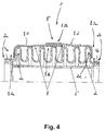
- FIG. 4 shows a variant of the not according to the invention, illustrative flexible conduit member 1, which basically the embodiment in FIG. 3 equivalent.
- the outer component 8.1, 8.2 is again formed in two parts and has a first outer component section 8.1 and a second outer component section 8.2.
- the definition of the outer component sections 8.1, 8.2 on the corrugated hose or bellows 2 now takes place according to FIG. 4 a constriction is formed in the region of the respective first ends 8.1a, 8.2a of the outer component sections 8.1, 8.2 so that the respective outer component section 8.1, 8.2 is held in a form-fitting manner behind the respective last wave crest 2c, 2d of the corrugated hose or bellows is.
- a suitable thread material can be used which in FIG. 4 is not explicitly drawn in order to constrict the outer component material in said areas and to secure it to the corrugated hose 2.
- a modification of the conduit element 1 according to FIG. 4 provides that the outer component sections 8.1, 8.2 are extended in the region of their respective first ends 8.1a, 8.2a to the region of the end sleeves 4a, 4b to the outer component sections 8.1, 8.2 together with the other components of the flexible conduit element 1 in the region of the terminal ends 2a, 2b to fix. If this is done materially, in particular by welding, the outer component material in the connection region preferably has a special configuration, which is now based on FIG. 5 will be discussed in more detail.
- FIG. 5 schematically shows a possible structure of the material of the inner component according to the FIGS. 1 and 2 or the outer component according to the Figures 3 and 4 .
- the material in question is in FIG. 5 denoted by both the reference numeral 6 and the reference numeral 8. It consists of a first (upper) layer 6c, 8c and a second (lower) layer 6d, 8d. Between the first layer, 6c, 8c and the second layer 6d, 8d, an intermediate layer 6e, 8e made of a thermally insulating material is arranged. This situation is in FIG. 5 shown to the left of the dashed vertical line.
- the first layer 6c, 8c and the second layer 6d, 8d are a metal foil or a mesh of fine metal wires, which may have a diameter in the range of 1/10 to 1/100 mm.
- the use of stainless steel comes into consideration. It is not necessary that the first layer 6c, 8c and the second layer 6d, 8d consist of one and the same material.
- the material of the intermediate layer 6e, 8e is preferably a ceramic material which has a thickness in the Range of 1 mm to 10 mm, preferably about 2 mm to 5 mm.
- FIG. 5 Right of the vertical dashed line in FIG. 5 lacks the intermediate layer, so that here the outer (metallic) layers 6c, 8c and 6d, 8d lie substantially directly on top of each other.
- the inner component 6 or outer component 8 is given a weldability with other components of the flexible conduit member, which in FIG. 5 are denoted by reference numerals 5 'and 7', 9 'by way of example with reference to Figures 1 to 4.
- the aforementioned weldability is shown symbolically at reference symbol S.
- the thermally insulating material of the intermediate layer 6e, 8e may be formed relatively stiff in the axial direction, because the axial mobility of the overall arrangement is ensured by the common sliding seat all shown embodiments.
- the inner component 6 and the outer component 8 or their first and second sections 6.1, 6.2, 8.1, 8.2 still have a circumferential metal ring, which is not explicitly shown in the figures.
- This metal ring can be incorporated into the material of the inner component or outer component and ensures that it permanently retains a defined geometric shape in the region of its free end.
Landscapes
- Engineering & Computer Science (AREA)
- Chemical & Material Sciences (AREA)
- Combustion & Propulsion (AREA)
- Mechanical Engineering (AREA)
- General Engineering & Computer Science (AREA)
- Thermal Insulation (AREA)
- Rigid Pipes And Flexible Pipes (AREA)
Description
- Die vorliegende Erfindung betrifft ein flexibles Leitungselement nach dem Oberbegriff des Anspruchs 1 für den Abgasstrang eines Kraftfahrzeugs mit Verbrennungsmotor, welches Leitungselement zumindest einen metallischen Wellschlauch oder Balg aufweist, welcher Wellschlauch oder Balg zumindest abschnittweise mit einem radial innenliegenden ersten Innenkomponente-Abschnitt versehen ist, welcher erste Innenkomponente-Abschnitt zumindest teilweise in einem thermisch isolierenden Material ausgebildet, an seinem ersten Ende fest mit dem Wellschlauch oder Balg oder mit einem ersten weiteren Bestandteil des Leitungselements verbunden und an seinem zweiten Ende in einem Schiebesitz mit einem zweiten weiteren Bestandteil des Leitungselements befindlich ist.
- Derartige flexible Leitungselemente sind dem Fachmann bekannt und werden in Abgasstrang eines Kraftfahrzeugs mit Verbrennungsmotor als so genannte Entkoppelelemente (EKE) eingesetzt, insbesondere auch in Abgas-Rückführleitungen (EGR).
- Die angesprochenen flexiblen Leitungselemente dienen zur Entkopplung der motorseitigen Schwingungen und kommen dabei zwischen dem sogenannten "hot end" und dem so genannten "cold end" des Verbrennungsmotors zum Einsatz. Um in diesem Zusammenhang die zukünftigen Abgasnormen (beispielsweise die Norm EU6) erfüllen zu können, ist es wichtig, den Schadstoffgehalt im Abgas des Verbrennungsmotors auf die geforderten Werte zu reduzieren. Dafür ist es entscheidend, dass bereits vorhandene Prozesse zur Abgasreinigung optimal genutzt werden können. Eine Grundvoraussetzung hierfür ist eine sofortige Wärmebereitstellung an den zur Abgasreinigung verwendeten Katalysatoren. Mit anderen Worten: es ist dafür Sorge zu tragen, dass der Wärmeinhalt des Abgases auf dem Weg zum Katalysator nicht "verloren geht", was insbesondere bei einem Kaltstart des Motors bei flexiblen Leitungselementen nach dem Stand der Technik jedoch regelmäßig auftritt.
- Es hat sich nämlich herausgestellt, dass heutige Abgasanlagen bzw. Abgasstränge und insbesondere die darin Verwendung findenden flexiblen Leitungselemente auf der Strecke bis zum Katalysator einen zu großen Wärmeverlust durch Abstrahlung aufweisen, so dass die volle Wirksamkeit der Abgasreinigung erst verzögert auftritt. Somit sind die Abgaswerte in der anfänglichen "kalten Phase" nach dem Stand der Technik noch zu hoch, so dass die genannten Abgasnormen nicht oder nicht ausreichend eingehalten werden.
- Es hat sich allerdings gezeigt, dass Isoliermaterialien, insbesondere Isoliergewebe, die zur Vermeidung von Wärmeverlusten durch Abstrahlung grundsätzlich einsetzbar wären, nicht die für Entkoppelelemente zu fordernde axiale Flexibilität aufweisen, so dass beispielsweise eine einfache Umhüllung eines an sich bekannten flexiblen Leitungselements mit einem solchen Isoliermaterial nicht in Betracht kommt.
- Die
DE 20 2008 013021 U1 offenbart eine Isoliervorrichtung eines Kompensators, bei der ein innenliegender Rohr-Kompensator nach Art eines flexiblen Wellrohrs in einem gewissen radialen Abstand außen von einem Isolier-Kompensator umgeben ist. - In der
US 5,145,215 A ist eine flexible Kopplungsvorrichtung gezeigt. Hierbei sind innerhalb eines Balgs zwei starre, einander teilweise überlappende Rohrleitungsabschnitte nach Art von Flammrohren angeordnet, zwischen denen sich ein poröses Abstandselement befindet. - Der Erfindung liegt die Aufgabe zugrunde, ein flexibles Leitungselement der eingangs genannten Art gegen Wärmeverlust zu isolieren, ohne dabei die gewünschten flexiblen Eigenschaften des flexiblen Leitungselements preiszugeben.
- Diese Aufgabe wird erfindungsgemäß gelöst durch ein flexibles Leitungselement mit den Merkmalen des Anspruchs 1. Vorteilhafte Weiterbildungen der Erfindung sind Gegenstand von Unteransprüchen, deren Wortlaut hiermit durch ausdrückliche Bezugnahme in die Beschreibung aufgenommen wird, um Textwiederholungen nach Möglichkeit zu vermeiden.
- Erfindungsgemäß ist ein flexibles Leitungselement für den Abgasstrang eines Kraftfahrzeugs mit Verbrennungsmotor, welches Leitungselement zumindest einen metallischen Wellschlauch oder Balg aufweist, welcher Wellschlauch oder Balg zumindest abschnittweise mit einem radial innenliegenden ersten Innenkomponente-Abschnitt versehen ist, welcher erste Innenkomponente-Abschnitt zumindest teilweise in einem thermisch isolierenden Material ausgebildet, an seinem ersten Ende fest mit dem Wellschlauch oder Balg oder mit einem ersten weiteren Bestandteil des Leitungselements verbunden und an seinem zweiten Ende in einem Schiebesitz mit einem zweiten weiteren Bestandteil des Leitungselements befindlich ist, dadurch gekennzeichnet, dass
- a) der erste weitere Bestandteil und der zweite weitere Bestandteil jeweils als ein Flammrohr ausgebildet sind; oder dass
- b) der erste weitere Bestandteil als Flammrohr ausgebildet ist und der zweite weitere Bestandteil als ein zweiter Innenkomponente-Abschnitt zumindest teilweise in einem thermisch isolierenden Material ausgebildet ist, welcher zweite Innenkomponente-Abschnitt mit seinem ersten Ende an einem zweiten Flammrohr befestigt ist, und welcher zweite Innenkomponente-Abschnitt an seinem zweiten Ende im Schiebesitz mit dem ersten Innenkomponente-Abschnitt befindlich ist;
- Für den genannten Abschnitt der Innenkomponente kommt ein thermisch isolierendes Material nach Art eines Isoliergewebes oder dergleichen zum Einsatz, welches vorzugsweise die bei Entkoppelelementen regelmäßig auftretenden angularen und lateralen Bewegungen bzw. Verformungen aufnehmen kann. Allerdings sind derartige Isoliermaterialien - wie bereits ausgeführt - regelmäßig nicht in der Lage, axiale Bewegungen aufzunehmen. Deshalb wird das Isoliermaterial erfindungsgemäß nur an seinem ersten Ende fest mit dem Wellschlauch oder Balg oder mit einem anderen Bestandteil des Leitungselements verbunden und an seinem anderen Ende über einen weiteren Bestandteil des Leitungselements lediglich übergestülpt, so dass es sich dort in einem Schiebesitz befindet.
- Auf diese Weise besitzt die Gesamtanordnung die zu fordernde axiale Beweglichkeit bzw. Flexibilität, da aufgrund des Schiebesitzes eine relative, axiale Beweglichkeit zwischen dem genannten Innenkomponente-Abschnitt und dem zweiten weiteren Bestandteil des Leitungselements gegeben ist. Auf mögliche konkrete Ausgestaltungen des ersten und des zweiten weiteren Bestandteils des Leitungselements wird weiter unten im Zuge bestimmter Ausgestaltungen des Erfindungsgegenstands noch genauer eingegangen. Selbst bei Verwendung eines axial vollständig steifen Isoliermaterials für die Innenkomponente wird somit die (axiale) Flexibilität des flexiblen Leitungselements nicht bzw. nicht wesentlich beeinträchtigt.
- Erfindungsgemäß ist vorgesehen, dass die Innenkomponente in dem thermisch isolierenden Material ausgebildet ist, und der erste weitere Bestandteil und der zweite weitere Bestandteil des Leitungselements jeweils als ein Flammrohr ausgebildet sind. Hierbei ist die axial steife Innenkomponente an dem einen Flammrohr festgelegt, während im Überlappungsbereich der Innenkomponente und des anderen Flammrohrs der bereits angesprochene Schiebesitz realisiert ist.
- Alternativ ist erfindungsgemäß vorgesehen, dass der erste weitere Bestandteil als Flammrohr und der zweite weitere Bestandteil als ein zweiter Innenkomponente-Abschnitt ausgebildet ist. Die beiden Innenkomponente-Abschnitte, welche als Gewebeschläuche ausgebildet sein können, überdecken bzw. überlappen sich dabei in der Mitte des Entkoppelelements und stellen somit die geforderte axiale Beweglichkeit her. Auch in diesem Zusammenhang ist sicherzustellen, dass eine ausreichende axiale Überlappung gegeben ist, um die auftretenden axialen Bewegungen des flexiblen Leitungselements vollständig aufnehmen zu können.
- Eine erste Weiterbildung des erfindungsgemäßen Leitungselements sieht vor, dass eine Abmessung des Überlappungsbereichs zwischen dem Innenkomponente-Abschnitt einerseits und dem zweiten weiteren Bestandteil des Leitungselements andererseits in axialer Richtung des Leitungselements größer ist als dessen maximale axiale Längung. Hierdurch ist sichergestellt, dass die maximal mögliche axiale Relativbewegung im Bereich des Schiebesitzes vollständig aufgenommen werden kann, ohne dass die übereinandergestülpten Bestandteile des Leitungselements voneinander rutschen. In gleicher Weise sieht eine andere Weiterbildung der vorliegenden Erfindung vor, dass im Bereich des Schiebesitzes ausreichend axialer Abstand zu weiteren Bestandteilen des Leitungselements gegeben ist, damit auch axiale Stauchungen des Leitungselements aufgenommen werden können.
- Sämtliche genannte Abschnitte des thermisch isolierenden Materials können kraftschlüssig mit einem betreffenden zugeordneten Bestandteil des Leitungselements verbunden sein. Bei den genannten zugeordneten Bestandteilen des Leitungselements handelt es sich nach dem Vorstehenden um ein Flammrohr. Vorzugsweise können hierzu Pressringe oder Presshülsen Verwendung finden, welche insbesondere durch mechanisches Verpressen oder berührungslos durch Magnetumformung zur Schaffung der kraftschlüssigen Verbindung umgeformt werden können. Eine derartige Anbindung der Innenkomponente ist insbesondere dann vorteilhaft, wenn das thermisch isolierende Material nur schlecht anderweitig mit den restlichen Bestandteilen des flexiblen Leitungselements verbindbar ist, beispielsweise aufgrund fehlender Schweißbarkeit.
- Eine alternative Ausgestaltung des erfindungsgemäßen Leitungselements sieht dagegen vor, dass die Anbindung der Innenkomponente-Abschnitte stoffschlüssig erfolgt, und zwar vorzugsweise im Bereich der genannten Flammrohre, welche in an sich bekannter Weise auch zum stoffschlüssigen Anbinden des Wellschlauchs oder Balgs dienen. Die angesprochene stoffschlüssige Verbindung kann insbesondere als Schweiß- oder Lötverbindung ausgebildet sein. Vorteilhafterweise kommen derartige Verbindungsarten zum Einsatz, wenn das thermisch isolierende Material der Innenkomponente zumindest im Anbindungsbereich eine ausreichende stoffschlüssige Anbindbarkeit besitzt oder wenn die Innenkomponente im Anbindebereich das thermisch isolierende Material nicht aufweist.
- Es hat sich als besonders vorteilhaft erwiesen, wenn im Zuge einer anderen Weiterbildung des erfindungsgemäßen Leitungselements zumindest einer der genannten Innenkomponente-Abschnitte einen mehrlagigen Aufbau aufweist. Ein solcher mehrlagiger Aufbau kann eine erste und eine zweite Lage aus einer metallischen Folie oder einem Metalldrahtgewebe umfassen, wobei zwischen den genannten ersten und zweiten Lagen als Zwischenlage ein thermisches Isoliermaterial angeordnet ist. Bei dem thermischen Isoliermaterial der Zwischenlage kann es sich um ein Keramikmaterial handeln, ohne dass sich die Erfindung auf ein derartiges Isoliermaterial beschränkt wäre.
- Um eine ausreichende thermische Isolierwirkung bei hinreichender Stabilität und vertretbarem Gewicht zu erreichen, hat es sich als vorteilhaft erwiesen, wenn die ersten und zweiten Lagen aus dünnen Metalldrähten, vorzugsweise aus Edelstahl mit einem Durchmesser im Bereich von 1/100 bis 1/10 mm gefertigt sind. Das (Keramik-)Material der Zwischenlage weist vorzugsweise eine Dicke im Bereich von 1 bis 10 mm, vorzugsweise etwa 2 bis 5 mm, auf. Insbesondere derartige mehrlagige Isoliermaterialien werden auch als Isoliergewebe bezeichnet und sind axial relativ steif, während sie in radialer und angularer Richtung eine auszeichnende Beweglichkeit aufweisen.
- Wenn eine stoffschlüssige Anbindung der Innenkomponente angestrebt wird, hat es sich als besonders vorteilhaft erwiesen, wenn das (mehrlagige) Material der Innenkomponente in solchen Teilabschnitten stoffschlüssig mit dem restlichen flexiblen Leitungselement verbunden wird, in dem es keine thermisch isolierende Zwischenlage, beispielsweise aus Keramikmaterial, aufweist.
- Auf diese Weise ermöglicht die vorliegende Erfindung die Wärmeisolierung von Entkoppelelementen. Aufgrund der Verwendung des thermisch isolierenden Materials im Bereich der Innenkomponente wird das Abgas bereits im Strom isoliert und eine Wärmeübertragung auf den Wellschlauch oder Balg verhindert. Eine äußerst bevorzugte Weiterbildung der Erfindung sieht in diesem Zusammenhang noch vor, dass das Gewebe an seiner Innenseite noch mit einer reflektierenden Innenschicht versehen wird, damit zusätzlich auch eine Wärmereflektion nach innen stattfinden kann.
- Die genannte Anordnung ermöglicht zusätzlich den Verzicht auf ein Innengestricke, welches nach dem Stand der Technik regelmäßig zu Dämpfungszwecken vorgesehen ist, da bereits das Isoliergewebe bzw. das thermisch isolierende Material schwingungsdämpfend wirkt. Auf diese Weise ergibt sich gegenüber dem Stand der Technik ein zusätzlicher Kostenvorteil.
- Wesentlich ist in jedem Fall, dass die aus einem thermisch isolierenden Material ausgebildete Innenkomponente nur auf einer Seite fest eingebunden ist und sich auf der anderen Seite relativ zu dem Leitungselement bzw. zu dessen Bestandteilen zumindest in axialer Richtung frei bewegen kann.
- Weitere Eigenschaften und Vorteile der vorliegenden Erfindung ergeben sich aus der nachfolgenden Beschreibung von Ausführungsbeispielen anhand der Zeichnung.
- Figur 1
- zeigt teilweise und im Längsschnitt eine erste Ausgestaltung des erfindungsgemäßen flexiblen Leitungselements gemäß Variante a;
- Figur 2
- zeigt teilweise und im Längsschnitt eine zweite Ausgestaltung des erfindungsgemäßen flexiblen Leitungselement gemäß Variante b;
- Figur 3
- zeigt teilweise und im Längsschnitt ein nicht erfindungsgemäßes, illustratives flexibles Leitungselement;
- Figur 4
- zeigt teilweise und im Längsschnitt ein weiteres nicht erfindungsgemäßes, illustratives flexibles Leitungselement; und
- Figur 5
- zeigt schematisch eine mögliche Ausgestaltung eines im Rahmen der vorliegenden Erfindung verwendeten Innenkomponente-Materials.
-
Figur 1 zeigt schematisch und im Längsschnitt eine erste Ausgestaltung des erfindungsgemäßen flexiblen Leitungselements gemäß Variante a, welches in seiner Gesamtheit mit dem Bezugszeichen 1 bezeichnet ist. Das flexible Leitungselement 1 ist zur Verwendung innerhalb des Abgasstrangs eines Kraftfahrzeugs mit Verbrennungsmotor vorgesehen. Es weist zu diesem Zweck einen metallischen Wellschlauch oder Balg 2 auf, der vorliegend mit einer radial außenliegenden Außenkomponente 3 nach Art eines metallischen Geflechts oder Gestrickes umgeben ist. Die Außenkomponente 3 umgibt den Wellschlauch oder Balg 2 über dessen volle axiale Länge und ist in glattzylindrischen Anschlussbereichen 2a, 2b des Wellschlauchs oder Balgs 2 unter radial außenliegenden Endhülsen 4a, 4b eingebunden. In den genannten glattzylindrischen Anschlussbereichen 2a, 2b des Wellschlauchs oder Balgs 2 weist das flexible Leitungselement weiterhin jeweils ein Flammrohr 5a, 5b auf, welche sich in axialer Richtung weiter nach innen, d.h. in den gewellten Bereich des Wellschlauchs oder Balgs 2 erstrecken. Hierbei nimmt der Innendurchmesser der Flammrohre 5a, 5b in der dargestellten bzw. in an sich bekannter Weise ab, um die angulare bzw. laterale Beweglichkeit des flexiblen Leitungselements 1 nicht zu beeinträchtigen. - Zum Zwecke einer optimierten Medienführung innerhalb des flexiblen Leitungselements 1 und zur thermischen Isolierung des geführten Mediums gegenüber Wärmeverlusten nach außen wird der freie Bereich zwischen den Flammrohren 5a und 5b durch einen Innenkomponente-Abschnitt bzw. eine Innenkomponente 6 überbrückt, welche Innenkomponente 6 die freien Enden der Flammrohre 5a, 5b radial außenliegend übergreift, wie in
Figur 1 dargestellt. Dabei ist die Innenkomponente 6 auf denjenigen Bereich der Flammrohr 5a, 5b beschränkt, in welchem Bereich diese - wie bereits angesprochen - ihren verringerten Innendurchmesser aufweisen. Die Innenkomponente 6 besteht zumindest teilweise aus einem thermisch isolierenden Material. Auf den genauen materiellen Aufbau der Innenkomponente 6 wird weiter unten anhand vonFigur 5 exemplarisch noch genauer eingegangen. - An ihrem ersten Ende (bei Bezugszeichen 6a) ist die Innenkomponente 6 fest mit dem Flammrohr 5a, d.h. einem ersten, anderen Bestandteil des flexiblen Leitungselements 1 verbunden. Gemäß der Ausgestaltung in
Figur 1 ist zu diesem Zweck ein Pressring oder eine Presshülse 7 vorgesehen, welcher bzw. welche das freie, innere Ende des Flammrohrs 5a und die Innenkomponente 6 im Bereich des ersten Endes 6a radial außenliegend übergreift. Durch geeignete Umformung (Verpressen) des Pressrings oder der Presshülse 7 kommt es so zu einer festen, kraftschlüssigen Verbindung zwischen dem Flammrohr 5a, der Innenkomponente 6 und dem Pressring bzw. der Presshülse 7. Die angesprochene Umformung kann beispielsweise durch mechanisches Verpressen erfolgen. Alternativ ist auch der Einsatz von Magnetumformung, insbesondere schneller Magnetumformung (SMU), möglich. - An ihrem zweiten Ende 6b (rechts in
Figur 1 ) ist die Innenkomponente 6 dagegen nicht an dem Flammrohr 5b festgelegt, sondern übergreift dieses lediglich in einem Überlappungsbereich B radial außenliegend nach Art eines Schiebesitzes. Dabei ist die Breite des Überlappungsbereichs B in axialer Richtung des flexiblen Leitungselements 1 derart gewählt, dass sowohl Längungen als auch Stauchungen des flexiblen Leitungselements 1 bzw. des Wellschlauchs oder Balgs 2 aufgenommen werden können. Dieser Bewegungs-Aufnahmebereich ist inFigur 1 mit "± x" bezeichnet. - Aufgrund der vorgeschlagenen Ausgestaltung des flexiblen Leitungselements 1 lässt sich für die Innenkomponente 6 ein besonders gut thermisch isolierendes Material verwenden, welches im Wesentlichen keine Flexibilität in axialer Richtung aufweisen muss. Hierauf wird weiter unten anhand von
Figur 5 noch genauer eingegangen. - An dieser Stelle sei angemerkt, dass insbesondere bei entsprechender Ausgestaltung des Materials der Innenkomponente 6 im Bereich des ersten Endes 6a auch eine stoffschlüssige Verbindung der Innenkomponente 6 und Flammrohr 5a am ersten Ende 6a der Innenkomponente 6 in Betracht kommt, worauf ebenfalls weiter unten anhand von
Figur 5 noch genauer eingegangen wird. - Die Verbindung von Endhülse 4a, 4b, Außenkomponente 3, Flammrohr 5a, 5b und Wellschlauch oder Balg 2 im Bereich der Anschlussenden 2a, 2b erfolgt insbesondere stoffschlüssig, vorzugsweise durch Verschweißen, was dem Fachmann an sich bekannt und deshalb in
Figur 1 nicht explizit dargestellt ist. -
Figur 2 zeigt eine alternative Ausgestaltung des erfindungsgemäßen flexiblen Leitungselements 1, wobei hier und im Folgenden gleiche Bezugszeichen gleiche oder gleichwirkende Elemente bezeichnen. Es sei nachfolgend nur auf die Unterschiede der Ausgestaltungen gemäßFigur 1 undFigur 2 genauer eingegangen. - Gemäß der Ausgestaltung der Variante b in
Figur 2 ist die Innenkomponente 6 zweigeteilt und weist einen ersten Innenkomponente-Abschnitt 6.1 und einen zweiten Innenkomponente-Abschnitt 6.2 auf. Der erste Innenkomponente-Abschnitt 6.1 ist mit seinem ersten Ende 6.1a analog zur Ausgestaltung gemäßFigur 1 mittels eines Pressrings oder einer Presshülse 7a an dem Flammrohr 5a festgelegt. Gleiches gilt für den zweiten Innenkomponente-Abschnitt 6.2, welcher mit seinem ersten Ende 6.2a mittels eines weiteren Pressrings (Presshülse) 7b an dem Flammrohr 5b befestigt ist. Im Bereich ihrer jeweiligen zweiten Enden 6.1 b, 6.2b überlappen die Innenkomponente-Abschnitte 6.1, 6.2 in einem Überlappungsbereich B', welcher in etwa mittig bezüglich der Längserstreckung des flexiblen Leitungselements 1 angeordnet ist. Wie der Fachmann erkennt, ist die Ausgestaltung inFigur 2 jedoch keinesfalls auf eine derartige mittige Anordnung des Überlappungsbereichs B' beschränkt. Da sich die Enden 6.1b, 6.2b der Innenkomponente-Abschnitte 6.1, 6.2 in axialer Richtung relativ zueinander bewegen können, ist auch im Falle der Ausgestaltung gemäßFigur 2 für eine axiale Beweglichkeit des flexiblen Leitungselements 1 gesorgt, selbst wenn es sich bei dem Material der Innenkomponente 6 um ein in axialer Richtung steifes thermisches Isoliermaterial handelt. - Bei einem nicht erfindungsgemäßen, illustrativen flexiblen Leitungselements 1 gemäß
Figur 3 ist die Innenkomponente 6' in an sich bekannter Weise nach Art eines Innenliners oder dergleichen ausgebildet, welcher per se eine gewisse axiale Flexibilität aufweist, dabei jedoch in der Regel keine thermisch isolierenden Eigenschaften besitzt. Dafür entfallen bei der Ausgestaltung gemäßFigur 3 die inFigur 1 undFigur 2 dargestellten Flammrohre. Innenkomponente (Innenliner) 6' sowie Wellschlauch oder Balg 2 und die Endhülsen 4a, 4b sind an den Anschlussenden 2a, 2b in an sich bekannter Weise miteinander verbunden, vorzugsweise stoffschlüssig durch Verschweißen. - Gemäß
Figur 3 ist nun die dort mit Bezugszeichen 8 bezeichnete Außenkomponente in einem axial steifen, thermisch isolierenden Material ausgebildet und besteht in diesem Zusammenhang aus einem ersten Außenkomponente-Abschnitt 8.1 und einen zweiten Außenkomponente-Abschnitt 8.2, die sich bei Bezugszeichen B" in einem betreffenden Überlappungsbereich axial überlappen. Dies geschieht im Bereich der jeweiligen zweiten Enden 8.1 b, 8.2b der Außenkomponente-Abschnitte 8.1, 8.2. Mit ihren jeweiligen ersten Enden 8.1a, 8.2a sind die Außenkomponente-Abschnitte 8.1, 8.2 dagegen jeweils auf dem endständigen Wellenberg 2c, 2d des Wellschlauchs oder Balgs 2 festgelegt, und zwar jeweils mittels eines radial außen angeordneten Pressrings 9a, 9b bzw. einer entsprechenden Presshülse. Auch hier kann die Befestigung der Außenkomponente-Abschnitte 8.1, 8.2 auf dem Wellschlauch oder Balg 2 durch mechanisches Verpressen, durch Magnetumformung (SMU) oder in vergleichbarer Weise erfolgen. -
Figur 4 zeigt eine Variante des nicht erfindungsgemäßen, illustrativen flexiblen Leitungselements 1, welche grundsätzlich der Ausgestaltung inFigur 3 entspricht. Die Außenkomponente 8.1, 8.2 ist wiederum zweiteilig ausgebildet und weist einen ersten Außenkomponente-Abschnitt 8.1 und einen zweiten Außenkomponente-Abschnitt 8.2 auf. Die Festlegung der Außenkomponente-Abschnitte 8.1, 8.2 an dem Wellschlauch oder Balg 2 erfolgt nun gemäßFigur 4 dergestalt, dass im Bereich der jeweiligen ersten Enden 8.1 a, 8.2a der Außenkomponente-Abschnitte 8.1, 8.2 eine Einschnürung ausgebildet ist, so dass der jeweilige Außenkomponente-Abschnitt 8.1, 8.2 formschlüssig hinter dem jeweils letzten Wellenberg 2c, 2d des Wellschlauchs oder Balgs gehalten ist. Zu diesem Zweck kann beispielsweise ein geeignetes Fadenmaterial verwendet werden, welches inFigur 4 nicht explizit eingezeichnet ist, um das Außenkomponente-Material in den genannten Bereichen einzuschnüren und formschlüssig an dem Wellschlauch 2 zu befestigen. - Eine Abwandlung des Leitungselements 1 gemäß
Figur 4 sieht vor, dass die Außenkomponente-Abschnitte 8.1, 8.2 im Bereich ihrer jeweiligen ersten Enden 8.1a, 8.2a bis in den Bereich der Endhülsen 4a, 4b verlängert sind, um die Außenkomponente-Abschnitte 8.1, 8.2 zusammen mit den weiteren Bestandteilen des flexiblen Leitungselements 1 im Bereich der Anschlussenden 2a, 2b zu fixieren. Sofern dies stoffschlüssig erfolgt, insbesondere durch Verschweißen, weist das Außenkomponente-Material im Verbindungsbereich vorzugsweise eine besondere Ausgestaltung auf, worauf nun anhand vonFigur 5 noch genauer eingegangen wird. -
Figur 5 zeigt schematisch einen möglichen Aufbau des Materials der Innenkomponente gemäß denFiguren 1 und2 bzw. der Außenkomponente gemäß denFiguren 3 und4 . Dabei ist das betreffende Material inFigur 5 sowohl mit dem Bezugszeichen 6 als auch mit dem Bezugszeichen 8 bezeichnet. Es besteht aus einer ersten (oberen) Lage 6c, 8c und einer zweiten (unteren) Lage 6d, 8d. Zwischen der ersten Lage, 6c, 8c und der zweiten Lage 6d, 8d ist eine Zwischenlage 6e, 8e aus einem thermisch isolierenden Material angeordnet. Dieser Sachverhalt ist inFigur 5 links der vertikal gestrichelten Linie dargestellt. - Vorzugsweise handelt es sich bei der ersten Lage 6c, 8c und der zweiten Lage 6d, 8d um eine Metallfolie oder um ein Gewebe aus feinen Metalldrähten, welche einen Durchmesser im Bereich von 1/10 bis zu 1/100 mm aufweisen können. Insbesondere kommt die Verwendung von Edelstahl in Betracht. Dabei ist es nicht erforderlich, dass die erste Lage 6c, 8c und die zweite Lage 6d, 8d aus ein und demselben Material bestehen. Bei dem Material der Zwischenlage 6e, 8e handelt es sich vorzugsweise um ein Keramikmaterial, welches eine Dicke im Bereich von 1 mm bis 10 mm, vorzugsweise etwa 2 mm bis 5 mm, aufweisen kann.
- Rechts der vertikal gestrichelten Linie in
Figur 5 fehlt die Zwischenlage, so dass hier die äußeren (metallischen) Lagen 6c, 8c und 6d, 8d im Wesentlichen direkt aufeinander liegen. Bei einer solchen Ausgestaltung der Innenkomponente 6 bzw. Außenkomponente 8 ist eine Verschweißbarkeit mit weiteren Bestandteilen des flexiblen Leitungselements gegeben, welche inFigur 5 in Anlehnung an Figuren 1 bis 4 exemplarisch mit Bezugszeichen 5' bzw. 7', 9' bezeichnet sind. Die angesprochene Verschweißbarkeit ist bei Bezugszeichen S symbolhaft dargestellt. Auf die Möglichkeit einer entsprechenden stoffschlüssigen Anbindung der Innenkomponente 6 bzw. Außenkomponente 8 wurde weiter oben unter Bezugnahme auf dieFiguren 1 ,2 und4 bereits explizit hingewiesen. - Wie ebenfalls bereits erwähnt, kann das thermisch isolierende Material der Zwischenlage 6e, 8e in axialer Richtung relativ steif ausgebildet sein, weil die axiale Beweglichkeit der Gesamtanordnung durch den allen gezeigten Ausgestaltungen gemeinen Schiebesitz gewährleistet ist.
- An ihren freien Enden können die Innenkomponente 6 und die Außenkomponente 8 bzw. deren erste und zweite Abschnitte 6.1, 6.2, 8.1, 8.2 noch einen umlaufenden Metallring aufweisen, welcher in den Figuren nicht explizit dargestellt ist. Dieser Metallring kann in das Material der Innenkomponente bzw. Außenkomponente eingearbeitet sein und sorgt dafür, dass diese im Bereich ihres freien Endes eine definierte geometrische Form dauerhaft beibehält.
Claims (8)
- Flexibles Leitungselement (1) für den Abgasstrang eines Kraftfahrzeugs mit Verbrennungsmotor, welches Leitungselement zumindest einen metallischen Wellschlauch oder Balg (2) aufweist, welcher Wellschlauch oder Balg zumindest abschnittweise mit einem radial innenliegenden ersten Innenkomponente-Abschnitt (6, 6.1) versehen ist, welcher erste Innenkomponente-Abschnitt (6, 6.1) zumindest teilweise in einem thermisch isolierenden Material (6e) ausgebildet, an seinem ersten Ende (6a, 6.1a) fest mit dem Wellschlauch oder Balg (2) oder mit einem ersten weiteren Bestandteil (5a) des Leitungselements (1) verbunden und an seinem zweiten Ende (6b, 6.1b) in einem Schiebesitz mit einem zweiten weiteren Bestandteil (5b, 6.2) des Leitungselements befindlich ist,
dadurch gekennzeichnet, dassa) der erste weitere Bestandteil (5a) und der zweite weitere Bestandteil (5b) jeweils als ein Flammrohr ausgebildet sind; oder dassb) der erste weitere Bestandteil (5a) als Flammrohr ausgebildet ist und der zweite weitere Bestandteil als ein zweiter Innenkomponente-Abschnitt (6.2) zumindest teilweise in einem thermisch isolierenden Material (6e) ausgebildet ist, welcher zweite Innenkomponente-Abschnitt (6.2) mit seinem ersten Ende (6.2a) an einem zweiten Flammrohr (5b) befestigt ist, und welcher zweite Innenkomponente-Abschnitt (6.2) an seinem zweiten Ende (6.2b) im Schiebesitz mit dem ersten Innenkomponente-Abschnitt (6, 6.1) befindlich ist;wobei die beiden Flammrohre (5a, 5b) in axialer Richtung des Leitungselements (1) voneinander beabstandet sind und dieser Abstand bei Variante a) von dem ersten Innenkomponente-Abschnitt (6, 6.1) und bei Variante b) von dem ersten Innenkomponente-Abschnitt (6.1) und dem zweiten Innenkomponente-Abschnitt (6.2) überbrückt ist. - Flexibles Leitungselement (1) nach Anspruch 1,
dadurch gekennzeichnet, dass
eine Abmessung des Überlapps (B, B') zwischen dem ersten Innenkomponente-Abschnitt (6, 6.1) einerseits und dem zweiten weiteren Bestandteil (5b, 6.2) des Leitungselements (1) andererseits in axialer Richtung des Leitungselements größer ist als dessen maximale axiale Längung. - Flexibles Leitungselement (1) nach einem der Ansprüche 1 oder 2,
dadurch gekennzeichnet, dass
der erste Innenkomponente-Abschnitt (6, 6.1) und/oder der zweite Innenkomponente-Abschnitt (6.2) an seinem jeweils ersten Ende (6a, 6.1a, 6.2a) kraftschlüssig mit einem betreffenden zugeordneten Flammrohr (5a, 5b) verbunden ist, vorzugsweise mittels eines Pressrings (7, 7a, 7b), höchst vorzugsweise durch Magnetumformung. - Flexibles Leitungselement (1) nach mindestens einem der Ansprüche 1 bis 3,
dadurch gekennzeichnet, dass
der erste Innenkomponente-Abschnitt (6, 6.1) und/oder der zweite Innenkomponente-Abschnitt (6.2) an seinem jeweils ersten Ende (6a, 6.1a, 6.2a) stoffschlüssig mit einem betreffenden zugeordneten Flammrohr (5a, 5b) des Leitungselements verbunden ist, höchst vorzugsweise durch Verschweißen oder durch Löten. - Flexibles Leitungselement (1) nach mindestens einem der Ansprüche 1 bis 4,
dadurch gekennzeichnet, dass
der erste Innenkomponente-Abschnitt (6, 6.1) und/oder der zweite Innenkomponente-Abschnitt (6.2) im Wesentlichen keine Flexibilität in axialer Richtung des Leitungselements (1) aufweist. - Flexibles Leitungselement (1) nach mindestens einem der Ansprüche 1 bis 5,
dadurch gekennzeichnet, dass
der erste Innenkomponente-Abschnitt (6, 6.1) und/oder der zweite Innenkomponente-Abschnitt (6.2) einen mehrlagigen Aufbau (6c-e) aufweist. - Flexibles Leitungselement (1) nach Anspruch 6,
dadurch gekennzeichnet, dass
der erste Innenkomponente-Abschnitt (6, 6.1) und/oder der zweite Innenkomponente-Abschnitt (6.2) eine erste (6c) und eine zweite Lage (6d) aus einer metallischen Folie oder einem Metalldrahtgewebe aufweist, zwischen welcher ersten und zweiten Lage als Zwischenlage (6e) ein thermisches Isoliermaterial angeordnet ist, vorzugsweise ein Keramikmaterial. - Flexibles Leitungselement nach Anspruch 7,
dadurch gekennzeichnet, dass
der erste Innenkomponente-Abschnitt (6, 6.1) und/oder der zweite Innenkomponente-Abschnitt (6.2) in einem Teilabschnitt, in welchem Teilabschnitt der betreffende Innenkomponente-Abschnitt mit einem weiteren Bestandteil (4a, 4b, 5a, 5b, 7, 7a, 7b) des Leitungselements (1) stoffschlüssig verbunden ist, keine thermisch isolierende Zwischenlage (6e) aufweist.
Applications Claiming Priority (1)
| Application Number | Priority Date | Filing Date | Title |
|---|---|---|---|
| DE201210200396 DE102012200396A1 (de) | 2012-01-12 | 2012-01-12 | Thermisch isoliertes flexibles Leitungselement |
Publications (2)
| Publication Number | Publication Date |
|---|---|
| EP2615272A1 EP2615272A1 (de) | 2013-07-17 |
| EP2615272B1 true EP2615272B1 (de) | 2017-04-19 |
Family
ID=47278161
Family Applications (1)
| Application Number | Title | Priority Date | Filing Date |
|---|---|---|---|
| EP12193510.0A Not-in-force EP2615272B1 (de) | 2012-01-12 | 2012-11-21 | Thermisch isoliertes flexibles Abgasleitungselement |
Country Status (2)
| Country | Link |
|---|---|
| EP (1) | EP2615272B1 (de) |
| DE (1) | DE102012200396A1 (de) |
Families Citing this family (2)
| Publication number | Priority date | Publication date | Assignee | Title |
|---|---|---|---|---|
| DE102014114470A1 (de) * | 2014-10-06 | 2016-04-07 | Witzenmann Gmbh | Verfahren zum Einbinden eines metallischen flexiblen Leitungselements in eine Fluidleitung und flexibles Leitungselement |
| DE102023004324B3 (de) | 2023-10-27 | 2025-02-20 | Mercedes-Benz Group AG | Leitungseinrichtung für ein Kraftfahrzeug sowie Verbrennungskraftmaschine für ein Kraftfahrzeug |
Family Cites Families (21)
| Publication number | Priority date | Publication date | Assignee | Title |
|---|---|---|---|---|
| FR1244446A (fr) * | 1959-09-18 | 1960-10-28 | Soudure Autogene Francaise | Joint d'accouplement orientable pour tuyauterie |
| DE2459180C3 (de) * | 1974-12-14 | 1978-05-03 | Hawiko Kompensatoren- U. Apparatebau Gmbh & Co Kg, 5830 Schwelm | Kompensatorverbindung für heiße Medien, insbesondere für Heinwinddüsenstöcke eines Hochofens |
| DE3427998A1 (de) * | 1984-07-28 | 1986-01-30 | Witzenmann GmbH, Metallschlauch-Fabrik Pforzheim, 7530 Pforzheim | Abgasleitung fuer kraftfahrzeugmotoren |
| DE3610684A1 (de) * | 1986-03-29 | 1987-01-02 | Witzenmann Metallschlauchfab | Gelenkige verbindung von rohrteilen, insbesondere bei abgasleitungen von kraftfahrzeugen |
| DE3526481A1 (de) * | 1985-07-24 | 1987-01-29 | Witzenmann Metallschlauchfab | Verbindung zweier rohrenden durch ein wellrohr |
| FR2598776A1 (fr) * | 1986-05-16 | 1987-11-20 | Tubest Sa | Dispositif d'accouplement entre deux conduits tubulaires. |
| US5145215A (en) * | 1991-04-26 | 1992-09-08 | Senior Engineering Investments, B.V. | Flexible coupler apparatus |
| US5167430A (en) * | 1991-11-19 | 1992-12-01 | Manville Corporation | Automotive exhaust system decoupler with resilient sleeve |
| JP2959307B2 (ja) * | 1992-09-08 | 1999-10-06 | トヨタ自動車株式会社 | 内燃機関の排気管 |
| US5992896A (en) * | 1995-12-08 | 1999-11-30 | Senior Engineering Investments Ag | Flexible coupler apparatus |
| US5769464A (en) * | 1996-04-24 | 1998-06-23 | Titeflex Canada Ltd. | Flexible joint for metallic pipes |
| DE19706191A1 (de) * | 1997-02-18 | 1998-08-20 | Witzenmann Metallschlauchfab | Gelenkiges Verbindungselement für Rohrteile |
| KR100353123B1 (ko) * | 2000-08-28 | 2002-09-16 | 주식회사 에스제이엠 | 자동차 배기관용 연결구 |
| US6568715B2 (en) * | 2001-05-17 | 2003-05-27 | Senior Investments Ag | Vibration decoupling exhaust connector |
| FR2835018B1 (fr) * | 2002-01-22 | 2005-09-09 | Hutchinson | Perfectionnement a un flexible de decouplage pour ligne d'echappement d'un moteur de vehicule automobile |
| DE10248585A1 (de) * | 2002-10-17 | 2004-04-29 | Westfalia Metallschlauchtechnik Gmbh & Co. Kg | Verbindungselement für schwingbeanspruchte Rohrleitungen |
| ZA200505137B (en) * | 2002-12-26 | 2006-09-27 | Hirotec Corp | Flexible tube |
| DE102004027104A1 (de) * | 2004-06-03 | 2005-12-22 | Deutz Ag | Abgassammelleitung für eine mehrzylindrige Brennkraftmaschine |
| DE102004047418B4 (de) * | 2004-09-28 | 2007-03-15 | Benteler Automobiltechnik Gmbh | Ausgleichsanordnung |
| DE202007013516U1 (de) * | 2007-09-27 | 2009-02-19 | Witzenmann Gmbh | Dämpfungsanordnung |
| EP2045451B1 (de) * | 2007-10-01 | 2012-12-12 | BDD Beteiligungs GmbH | Isoliervorrichtung eines Kompensators |
-
2012
- 2012-01-12 DE DE201210200396 patent/DE102012200396A1/de not_active Withdrawn
- 2012-11-21 EP EP12193510.0A patent/EP2615272B1/de not_active Not-in-force
Also Published As
| Publication number | Publication date |
|---|---|
| EP2615272A1 (de) | 2013-07-17 |
| DE102012200396A1 (de) | 2013-07-18 |
Similar Documents
| Publication | Publication Date | Title |
|---|---|---|
| EP0856648B1 (de) | Flexibles Leitungselement für Abgasleitungen | |
| EP1887194B1 (de) | Abgasreinigungseinrichtung | |
| DE10393976T5 (de) | Flexibles Rohr | |
| EP0797039A2 (de) | Leitungselement mit einem Balg aus Metall | |
| DE102013226893B4 (de) | Flexibler Schlauch für ein Abgasrohr eines Kraftfahrzeugs | |
| EP1048881B1 (de) | Kältemittelleitung für Klimaanlagen | |
| DE102007016149A1 (de) | Metallschlauchanordnung mit Innen- und Außenschlauch | |
| WO2011036245A1 (de) | Streckbarer wickelschlauch | |
| EP0681096A1 (de) | Flexibles Leitungselement für Abgasleitungen von Verbrennungsmotoren bei Kraftfahrzeugen | |
| DE102015100552B3 (de) | Stützring für ein Abgasführungssystem | |
| DE8717998U1 (de) | Flexible Abgasleitung für Kraftfahrzeuge | |
| DE102013106075B4 (de) | Vorrichtung zum schwingungsentkoppelten Verbinden zweier Einrichtungen einer Abgasanlage | |
| EP2615272A1 (de) | Thermisch isoliertes flexibles Leitungselement | |
| DE202007004757U1 (de) | Entkoppelelement mit Isolation | |
| DE102010037772A1 (de) | Fixierter Wickelschlauch | |
| EP1927803B1 (de) | Flexibles Leitungselement für innendruckbeaufschlagte Leitungen | |
| EP2995837A1 (de) | Kältemittelleitung | |
| DE102012216097B4 (de) | Entkoppelelement | |
| EP2730765B1 (de) | Flexibles Leitungselement | |
| EP2894312A1 (de) | Flexibles Leitungselement mit Isolierung | |
| WO2005024197A1 (de) | Flexibles leitungselement | |
| DE102009049475B4 (de) | Kompensator für Rohrleitungen | |
| DE102011087540A1 (de) | Flexibles Leitungsteil für fluidführende Leitungen eines Fahrzeugs | |
| DE202007006720U1 (de) | Entkoppelelement mit Verlängerung | |
| DE102011086840A1 (de) | Flexibles Leitungsteil, insbesondere für die Abgasanlage eines Verbrennungsmotors |
Legal Events
| Date | Code | Title | Description |
|---|---|---|---|
| PUAI | Public reference made under article 153(3) epc to a published international application that has entered the european phase |
Free format text: ORIGINAL CODE: 0009012 |
|
| AK | Designated contracting states |
Kind code of ref document: A1 Designated state(s): AL AT BE BG CH CY CZ DE DK EE ES FI FR GB GR HR HU IE IS IT LI LT LU LV MC MK MT NL NO PL PT RO RS SE SI SK SM TR |
|
| AX | Request for extension of the european patent |
Extension state: BA ME |
|
| 17P | Request for examination filed |
Effective date: 20131108 |
|
| RBV | Designated contracting states (corrected) |
Designated state(s): AL AT BE BG CH CY CZ DE DK EE ES FI FR GB GR HR HU IE IS IT LI LT LU LV MC MK MT NL NO PL PT RO RS SE SI SK SM TR |
|
| 17Q | First examination report despatched |
Effective date: 20160422 |
|
| GRAP | Despatch of communication of intention to grant a patent |
Free format text: ORIGINAL CODE: EPIDOSNIGR1 |
|
| STAA | Information on the status of an ep patent application or granted ep patent |
Free format text: STATUS: GRANT OF PATENT IS INTENDED |
|
| INTG | Intention to grant announced |
Effective date: 20161219 |
|
| GRAS | Grant fee paid |
Free format text: ORIGINAL CODE: EPIDOSNIGR3 |
|
| GRAA | (expected) grant |
Free format text: ORIGINAL CODE: 0009210 |
|
| STAA | Information on the status of an ep patent application or granted ep patent |
Free format text: STATUS: THE PATENT HAS BEEN GRANTED |
|
| AK | Designated contracting states |
Kind code of ref document: B1 Designated state(s): AL AT BE BG CH CY CZ DE DK EE ES FI FR GB GR HR HU IE IS IT LI LT LU LV MC MK MT NL NO PL PT RO RS SE SI SK SM TR |
|
| REG | Reference to a national code |
Ref country code: GB Ref legal event code: FG4D Free format text: NOT ENGLISH |
|
| REG | Reference to a national code |
Ref country code: CH Ref legal event code: EP |
|
| REG | Reference to a national code |
Ref country code: AT Ref legal event code: REF Ref document number: 886199 Country of ref document: AT Kind code of ref document: T Effective date: 20170515 |
|
| REG | Reference to a national code |
Ref country code: IE Ref legal event code: FG4D Free format text: LANGUAGE OF EP DOCUMENT: GERMAN |
|
| REG | Reference to a national code |
Ref country code: DE Ref legal event code: R096 Ref document number: 502012010104 Country of ref document: DE |
|
| REG | Reference to a national code |
Ref country code: NL Ref legal event code: MP Effective date: 20170419 |
|
| REG | Reference to a national code |
Ref country code: LT Ref legal event code: MG4D |
|
| PG25 | Lapsed in a contracting state [announced via postgrant information from national office to epo] |
Ref country code: NL Free format text: LAPSE BECAUSE OF FAILURE TO SUBMIT A TRANSLATION OF THE DESCRIPTION OR TO PAY THE FEE WITHIN THE PRESCRIBED TIME-LIMIT Effective date: 20170419 |
|
| PG25 | Lapsed in a contracting state [announced via postgrant information from national office to epo] |
Ref country code: FI Free format text: LAPSE BECAUSE OF FAILURE TO SUBMIT A TRANSLATION OF THE DESCRIPTION OR TO PAY THE FEE WITHIN THE PRESCRIBED TIME-LIMIT Effective date: 20170419 Ref country code: HR Free format text: LAPSE BECAUSE OF FAILURE TO SUBMIT A TRANSLATION OF THE DESCRIPTION OR TO PAY THE FEE WITHIN THE PRESCRIBED TIME-LIMIT Effective date: 20170419 Ref country code: NO Free format text: LAPSE BECAUSE OF FAILURE TO SUBMIT A TRANSLATION OF THE DESCRIPTION OR TO PAY THE FEE WITHIN THE PRESCRIBED TIME-LIMIT Effective date: 20170719 Ref country code: GR Free format text: LAPSE BECAUSE OF FAILURE TO SUBMIT A TRANSLATION OF THE DESCRIPTION OR TO PAY THE FEE WITHIN THE PRESCRIBED TIME-LIMIT Effective date: 20170720 Ref country code: ES Free format text: LAPSE BECAUSE OF FAILURE TO SUBMIT A TRANSLATION OF THE DESCRIPTION OR TO PAY THE FEE WITHIN THE PRESCRIBED TIME-LIMIT Effective date: 20170419 Ref country code: LT Free format text: LAPSE BECAUSE OF FAILURE TO SUBMIT A TRANSLATION OF THE DESCRIPTION OR TO PAY THE FEE WITHIN THE PRESCRIBED TIME-LIMIT Effective date: 20170419 |
|
| PG25 | Lapsed in a contracting state [announced via postgrant information from national office to epo] |
Ref country code: RS Free format text: LAPSE BECAUSE OF FAILURE TO SUBMIT A TRANSLATION OF THE DESCRIPTION OR TO PAY THE FEE WITHIN THE PRESCRIBED TIME-LIMIT Effective date: 20170419 Ref country code: IS Free format text: LAPSE BECAUSE OF FAILURE TO SUBMIT A TRANSLATION OF THE DESCRIPTION OR TO PAY THE FEE WITHIN THE PRESCRIBED TIME-LIMIT Effective date: 20170819 Ref country code: PL Free format text: LAPSE BECAUSE OF FAILURE TO SUBMIT A TRANSLATION OF THE DESCRIPTION OR TO PAY THE FEE WITHIN THE PRESCRIBED TIME-LIMIT Effective date: 20170419 Ref country code: BG Free format text: LAPSE BECAUSE OF FAILURE TO SUBMIT A TRANSLATION OF THE DESCRIPTION OR TO PAY THE FEE WITHIN THE PRESCRIBED TIME-LIMIT Effective date: 20170719 Ref country code: LV Free format text: LAPSE BECAUSE OF FAILURE TO SUBMIT A TRANSLATION OF THE DESCRIPTION OR TO PAY THE FEE WITHIN THE PRESCRIBED TIME-LIMIT Effective date: 20170419 Ref country code: SE Free format text: LAPSE BECAUSE OF FAILURE TO SUBMIT A TRANSLATION OF THE DESCRIPTION OR TO PAY THE FEE WITHIN THE PRESCRIBED TIME-LIMIT Effective date: 20170419 |
|
| REG | Reference to a national code |
Ref country code: DE Ref legal event code: R097 Ref document number: 502012010104 Country of ref document: DE |
|
| PG25 | Lapsed in a contracting state [announced via postgrant information from national office to epo] |
Ref country code: SK Free format text: LAPSE BECAUSE OF FAILURE TO SUBMIT A TRANSLATION OF THE DESCRIPTION OR TO PAY THE FEE WITHIN THE PRESCRIBED TIME-LIMIT Effective date: 20170419 Ref country code: RO Free format text: LAPSE BECAUSE OF FAILURE TO SUBMIT A TRANSLATION OF THE DESCRIPTION OR TO PAY THE FEE WITHIN THE PRESCRIBED TIME-LIMIT Effective date: 20170419 Ref country code: DK Free format text: LAPSE BECAUSE OF FAILURE TO SUBMIT A TRANSLATION OF THE DESCRIPTION OR TO PAY THE FEE WITHIN THE PRESCRIBED TIME-LIMIT Effective date: 20170419 Ref country code: EE Free format text: LAPSE BECAUSE OF FAILURE TO SUBMIT A TRANSLATION OF THE DESCRIPTION OR TO PAY THE FEE WITHIN THE PRESCRIBED TIME-LIMIT Effective date: 20170419 Ref country code: CZ Free format text: LAPSE BECAUSE OF FAILURE TO SUBMIT A TRANSLATION OF THE DESCRIPTION OR TO PAY THE FEE WITHIN THE PRESCRIBED TIME-LIMIT Effective date: 20170419 |
|
| PLBE | No opposition filed within time limit |
Free format text: ORIGINAL CODE: 0009261 |
|
| STAA | Information on the status of an ep patent application or granted ep patent |
Free format text: STATUS: NO OPPOSITION FILED WITHIN TIME LIMIT |
|
| PG25 | Lapsed in a contracting state [announced via postgrant information from national office to epo] |
Ref country code: SM Free format text: LAPSE BECAUSE OF FAILURE TO SUBMIT A TRANSLATION OF THE DESCRIPTION OR TO PAY THE FEE WITHIN THE PRESCRIBED TIME-LIMIT Effective date: 20170419 Ref country code: IT Free format text: LAPSE BECAUSE OF FAILURE TO SUBMIT A TRANSLATION OF THE DESCRIPTION OR TO PAY THE FEE WITHIN THE PRESCRIBED TIME-LIMIT Effective date: 20170419 |
|
| 26N | No opposition filed |
Effective date: 20180122 |
|
| PG25 | Lapsed in a contracting state [announced via postgrant information from national office to epo] |
Ref country code: SI Free format text: LAPSE BECAUSE OF FAILURE TO SUBMIT A TRANSLATION OF THE DESCRIPTION OR TO PAY THE FEE WITHIN THE PRESCRIBED TIME-LIMIT Effective date: 20170419 |
|
| REG | Reference to a national code |
Ref country code: DE Ref legal event code: R119 Ref document number: 502012010104 Country of ref document: DE |
|
| PG25 | Lapsed in a contracting state [announced via postgrant information from national office to epo] |
Ref country code: MC Free format text: LAPSE BECAUSE OF FAILURE TO SUBMIT A TRANSLATION OF THE DESCRIPTION OR TO PAY THE FEE WITHIN THE PRESCRIBED TIME-LIMIT Effective date: 20170419 |
|
| GBPC | Gb: european patent ceased through non-payment of renewal fee |
Effective date: 20171121 |
|
| PG25 | Lapsed in a contracting state [announced via postgrant information from national office to epo] |
Ref country code: CH Free format text: LAPSE BECAUSE OF NON-PAYMENT OF DUE FEES Effective date: 20171130 Ref country code: LI Free format text: LAPSE BECAUSE OF NON-PAYMENT OF DUE FEES Effective date: 20171130 |
|
| PG25 | Lapsed in a contracting state [announced via postgrant information from national office to epo] |
Ref country code: LU Free format text: LAPSE BECAUSE OF NON-PAYMENT OF DUE FEES Effective date: 20171121 |
|
| REG | Reference to a national code |
Ref country code: FR Ref legal event code: ST Effective date: 20180731 Ref country code: BE Ref legal event code: MM Effective date: 20171130 |
|
| REG | Reference to a national code |
Ref country code: IE Ref legal event code: MM4A |
|
| PG25 | Lapsed in a contracting state [announced via postgrant information from national office to epo] |
Ref country code: MT Free format text: LAPSE BECAUSE OF FAILURE TO SUBMIT A TRANSLATION OF THE DESCRIPTION OR TO PAY THE FEE WITHIN THE PRESCRIBED TIME-LIMIT Effective date: 20170419 |
|
| PG25 | Lapsed in a contracting state [announced via postgrant information from national office to epo] |
Ref country code: DE Free format text: LAPSE BECAUSE OF NON-PAYMENT OF DUE FEES Effective date: 20180602 Ref country code: FR Free format text: LAPSE BECAUSE OF NON-PAYMENT OF DUE FEES Effective date: 20171130 Ref country code: IE Free format text: LAPSE BECAUSE OF NON-PAYMENT OF DUE FEES Effective date: 20171121 |
|
| PG25 | Lapsed in a contracting state [announced via postgrant information from national office to epo] |
Ref country code: BE Free format text: LAPSE BECAUSE OF NON-PAYMENT OF DUE FEES Effective date: 20171130 Ref country code: GB Free format text: LAPSE BECAUSE OF NON-PAYMENT OF DUE FEES Effective date: 20171121 |
|
| REG | Reference to a national code |
Ref country code: AT Ref legal event code: MM01 Ref document number: 886199 Country of ref document: AT Kind code of ref document: T Effective date: 20171121 |
|
| PG25 | Lapsed in a contracting state [announced via postgrant information from national office to epo] |
Ref country code: AT Free format text: LAPSE BECAUSE OF NON-PAYMENT OF DUE FEES Effective date: 20171121 |
|
| PG25 | Lapsed in a contracting state [announced via postgrant information from national office to epo] |
Ref country code: HU Free format text: LAPSE BECAUSE OF FAILURE TO SUBMIT A TRANSLATION OF THE DESCRIPTION OR TO PAY THE FEE WITHIN THE PRESCRIBED TIME-LIMIT; INVALID AB INITIO Effective date: 20121121 |
|
| PG25 | Lapsed in a contracting state [announced via postgrant information from national office to epo] |
Ref country code: CY Free format text: LAPSE BECAUSE OF NON-PAYMENT OF DUE FEES Effective date: 20170419 |
|
| PG25 | Lapsed in a contracting state [announced via postgrant information from national office to epo] |
Ref country code: MK Free format text: LAPSE BECAUSE OF FAILURE TO SUBMIT A TRANSLATION OF THE DESCRIPTION OR TO PAY THE FEE WITHIN THE PRESCRIBED TIME-LIMIT Effective date: 20170419 |
|
| PG25 | Lapsed in a contracting state [announced via postgrant information from national office to epo] |
Ref country code: TR Free format text: LAPSE BECAUSE OF FAILURE TO SUBMIT A TRANSLATION OF THE DESCRIPTION OR TO PAY THE FEE WITHIN THE PRESCRIBED TIME-LIMIT Effective date: 20170419 |
|
| PG25 | Lapsed in a contracting state [announced via postgrant information from national office to epo] |
Ref country code: PT Free format text: LAPSE BECAUSE OF FAILURE TO SUBMIT A TRANSLATION OF THE DESCRIPTION OR TO PAY THE FEE WITHIN THE PRESCRIBED TIME-LIMIT Effective date: 20170419 |
|
| PG25 | Lapsed in a contracting state [announced via postgrant information from national office to epo] |
Ref country code: AL Free format text: LAPSE BECAUSE OF FAILURE TO SUBMIT A TRANSLATION OF THE DESCRIPTION OR TO PAY THE FEE WITHIN THE PRESCRIBED TIME-LIMIT Effective date: 20170419 |