EP2615063A1 - Method of producing silicon fine particles and method of controlling particle size of silicon fine particles - Google Patents
Method of producing silicon fine particles and method of controlling particle size of silicon fine particles Download PDFInfo
- Publication number
- EP2615063A1 EP2615063A1 EP11823677.7A EP11823677A EP2615063A1 EP 2615063 A1 EP2615063 A1 EP 2615063A1 EP 11823677 A EP11823677 A EP 11823677A EP 2615063 A1 EP2615063 A1 EP 2615063A1
- Authority
- EP
- European Patent Office
- Prior art keywords
- silicon
- fine particles
- particles
- silicon fine
- particle diameter
- Prior art date
- Legal status (The legal status is an assumption and is not a legal conclusion. Google has not performed a legal analysis and makes no representation as to the accuracy of the status listed.)
- Withdrawn
Links
- XUIMIQQOPSSXEZ-UHFFFAOYSA-N Silicon Chemical compound [Si] XUIMIQQOPSSXEZ-UHFFFAOYSA-N 0.000 title claims abstract description 132
- 229910052710 silicon Inorganic materials 0.000 title claims abstract description 132
- 239000010703 silicon Substances 0.000 title claims abstract description 132
- 239000010419 fine particle Substances 0.000 title claims abstract description 111
- 239000002245 particle Substances 0.000 title claims abstract description 95
- 238000000034 method Methods 0.000 title claims abstract description 21
- 239000011856 silicon-based particle Substances 0.000 claims abstract description 93
- 238000005530 etching Methods 0.000 claims abstract description 75
- 238000004519 manufacturing process Methods 0.000 claims abstract description 37
- 230000001678 irradiating effect Effects 0.000 claims abstract description 5
- VYPSYNLAJGMNEJ-UHFFFAOYSA-N Silicium dioxide Chemical compound O=[Si]=O VYPSYNLAJGMNEJ-UHFFFAOYSA-N 0.000 claims description 35
- 239000000843 powder Substances 0.000 claims description 24
- 239000002131 composite material Substances 0.000 claims description 22
- KRHYYFGTRYWZRS-UHFFFAOYSA-N Fluorane Chemical compound F KRHYYFGTRYWZRS-UHFFFAOYSA-N 0.000 claims description 21
- 239000000203 mixture Substances 0.000 claims description 18
- 229910052814 silicon oxide Inorganic materials 0.000 claims description 16
- 239000007789 gas Substances 0.000 claims description 15
- 229910000040 hydrogen fluoride Inorganic materials 0.000 claims description 14
- OKTJSMMVPCPJKN-UHFFFAOYSA-N Carbon Chemical compound [C] OKTJSMMVPCPJKN-UHFFFAOYSA-N 0.000 claims description 12
- 229910052799 carbon Inorganic materials 0.000 claims description 12
- 239000012298 atmosphere Substances 0.000 claims description 9
- 238000001816 cooling Methods 0.000 claims description 8
- 238000002360 preparation method Methods 0.000 claims description 7
- 239000000243 solution Substances 0.000 description 41
- 238000010438 heat treatment Methods 0.000 description 16
- 238000009826 distribution Methods 0.000 description 15
- 230000000052 comparative effect Effects 0.000 description 14
- LIVNPJMFVYWSIS-UHFFFAOYSA-N silicon monoxide Chemical compound [Si-]#[O+] LIVNPJMFVYWSIS-UHFFFAOYSA-N 0.000 description 14
- XKRFYHLGVUSROY-UHFFFAOYSA-N Argon Chemical compound [Ar] XKRFYHLGVUSROY-UHFFFAOYSA-N 0.000 description 10
- 239000003054 catalyst Substances 0.000 description 8
- 239000012535 impurity Substances 0.000 description 8
- 239000000377 silicon dioxide Substances 0.000 description 8
- 239000002904 solvent Substances 0.000 description 8
- 239000002994 raw material Substances 0.000 description 7
- QGZKDVFQNNGYKY-UHFFFAOYSA-N Ammonia Chemical compound N QGZKDVFQNNGYKY-UHFFFAOYSA-N 0.000 description 6
- OKKJLVBELUTLKV-UHFFFAOYSA-N Methanol Chemical compound OC OKKJLVBELUTLKV-UHFFFAOYSA-N 0.000 description 6
- 150000001299 aldehydes Chemical class 0.000 description 5
- 150000001412 amines Chemical class 0.000 description 5
- 229910052786 argon Inorganic materials 0.000 description 5
- 239000007788 liquid Substances 0.000 description 5
- 229920000642 polymer Polymers 0.000 description 5
- 238000006116 polymerization reaction Methods 0.000 description 5
- ISWSIDIOOBJBQZ-UHFFFAOYSA-N Phenol Chemical compound OC1=CC=CC=C1 ISWSIDIOOBJBQZ-UHFFFAOYSA-N 0.000 description 4
- 238000006243 chemical reaction Methods 0.000 description 4
- 230000000694 effects Effects 0.000 description 4
- 239000011261 inert gas Substances 0.000 description 4
- 239000012528 membrane Substances 0.000 description 4
- 230000001590 oxidative effect Effects 0.000 description 4
- KFZMGEQAYNKOFK-UHFFFAOYSA-N Isopropanol Chemical compound CC(C)O KFZMGEQAYNKOFK-UHFFFAOYSA-N 0.000 description 3
- MUBZPKHOEPUJKR-UHFFFAOYSA-N Oxalic acid Chemical compound OC(=O)C(O)=O MUBZPKHOEPUJKR-UHFFFAOYSA-N 0.000 description 3
- BOTDANWDWHJENH-UHFFFAOYSA-N Tetraethyl orthosilicate Chemical compound CCO[Si](OCC)(OCC)OCC BOTDANWDWHJENH-UHFFFAOYSA-N 0.000 description 3
- ZMANZCXQSJIPKH-UHFFFAOYSA-N Triethylamine Chemical compound CCN(CC)CC ZMANZCXQSJIPKH-UHFFFAOYSA-N 0.000 description 3
- 239000002253 acid Substances 0.000 description 3
- -1 alkoxy silanes Chemical class 0.000 description 3
- 229910021529 ammonia Inorganic materials 0.000 description 3
- 229910052681 coesite Inorganic materials 0.000 description 3
- 229910052906 cristobalite Inorganic materials 0.000 description 3
- 238000004132 cross linking Methods 0.000 description 3
- 239000000428 dust Substances 0.000 description 3
- 239000012212 insulator Substances 0.000 description 3
- 239000010680 novolac-type phenolic resin Substances 0.000 description 3
- 239000007800 oxidant agent Substances 0.000 description 3
- 239000011134 resol-type phenolic resin Substances 0.000 description 3
- 150000004756 silanes Chemical class 0.000 description 3
- 235000012239 silicon dioxide Nutrition 0.000 description 3
- 229910052682 stishovite Inorganic materials 0.000 description 3
- 239000000126 substance Substances 0.000 description 3
- 229910052905 tridymite Inorganic materials 0.000 description 3
- IJGRMHOSHXDMSA-UHFFFAOYSA-N Atomic nitrogen Chemical compound N#N IJGRMHOSHXDMSA-UHFFFAOYSA-N 0.000 description 2
- 239000004971 Cross linker Substances 0.000 description 2
- ROSDSFDQCJNGOL-UHFFFAOYSA-N Dimethylamine Chemical compound CNC ROSDSFDQCJNGOL-UHFFFAOYSA-N 0.000 description 2
- LFQSCWFLJHTTHZ-UHFFFAOYSA-N Ethanol Chemical compound CCO LFQSCWFLJHTTHZ-UHFFFAOYSA-N 0.000 description 2
- VEXZGXHMUGYJMC-UHFFFAOYSA-N Hydrochloric acid Chemical compound Cl VEXZGXHMUGYJMC-UHFFFAOYSA-N 0.000 description 2
- YNAVUWVOSKDBBP-UHFFFAOYSA-N Morpholine Chemical compound C1COCCN1 YNAVUWVOSKDBBP-UHFFFAOYSA-N 0.000 description 2
- AFBPFSWMIHJQDM-UHFFFAOYSA-N N-methylaniline Chemical compound CNC1=CC=CC=C1 AFBPFSWMIHJQDM-UHFFFAOYSA-N 0.000 description 2
- GRYLNZFGIOXLOG-UHFFFAOYSA-N Nitric acid Chemical compound O[N+]([O-])=O GRYLNZFGIOXLOG-UHFFFAOYSA-N 0.000 description 2
- JUJWROOIHBZHMG-UHFFFAOYSA-N Pyridine Chemical compound C1=CC=NC=C1 JUJWROOIHBZHMG-UHFFFAOYSA-N 0.000 description 2
- QAOWNCQODCNURD-UHFFFAOYSA-N Sulfuric acid Chemical compound OS(O)(=O)=O QAOWNCQODCNURD-UHFFFAOYSA-N 0.000 description 2
- 239000012670 alkaline solution Substances 0.000 description 2
- HUMNYLRZRPPJDN-UHFFFAOYSA-N benzaldehyde Chemical compound O=CC1=CC=CC=C1 HUMNYLRZRPPJDN-UHFFFAOYSA-N 0.000 description 2
- IISBACLAFKSPIT-UHFFFAOYSA-N bisphenol A Chemical compound C=1C=C(O)C=CC=1C(C)(C)C1=CC=C(O)C=C1 IISBACLAFKSPIT-UHFFFAOYSA-N 0.000 description 2
- 239000011248 coating agent Substances 0.000 description 2
- 238000000576 coating method Methods 0.000 description 2
- 238000010835 comparative analysis Methods 0.000 description 2
- 238000010586 diagram Methods 0.000 description 2
- CWAFVXWRGIEBPL-UHFFFAOYSA-N ethoxysilane Chemical compound CCO[SiH3] CWAFVXWRGIEBPL-UHFFFAOYSA-N 0.000 description 2
- 238000002474 experimental method Methods 0.000 description 2
- 239000000706 filtrate Substances 0.000 description 2
- 229910017604 nitric acid Inorganic materials 0.000 description 2
- 239000005011 phenolic resin Substances 0.000 description 2
- 229920001568 phenolic resin Polymers 0.000 description 2
- 150000002989 phenols Chemical class 0.000 description 2
- 239000012495 reaction gas Substances 0.000 description 2
- 239000007787 solid Substances 0.000 description 2
- JOXIMZWYDAKGHI-UHFFFAOYSA-N toluene-4-sulfonic acid Chemical compound CC1=CC=C(S(O)(=O)=O)C=C1 JOXIMZWYDAKGHI-UHFFFAOYSA-N 0.000 description 2
- GETQZCLCWQTVFV-UHFFFAOYSA-N trimethylamine Chemical compound CN(C)C GETQZCLCWQTVFV-UHFFFAOYSA-N 0.000 description 2
- KXGFMDJXCMQABM-UHFFFAOYSA-N 2-methoxy-6-methylphenol Chemical compound [CH]OC1=CC=CC([CH])=C1O KXGFMDJXCMQABM-UHFFFAOYSA-N 0.000 description 1
- QTWJRLJHJPIABL-UHFFFAOYSA-N 2-methylphenol;3-methylphenol;4-methylphenol Chemical compound CC1=CC=C(O)C=C1.CC1=CC=CC(O)=C1.CC1=CC=CC=C1O QTWJRLJHJPIABL-UHFFFAOYSA-N 0.000 description 1
- MHAJPDPJQMAIIY-UHFFFAOYSA-N Hydrogen peroxide Chemical compound OO MHAJPDPJQMAIIY-UHFFFAOYSA-N 0.000 description 1
- UEEJHVSXFDXPFK-UHFFFAOYSA-N N-dimethylaminoethanol Chemical compound CN(C)CCO UEEJHVSXFDXPFK-UHFFFAOYSA-N 0.000 description 1
- KWYUFKZDYYNOTN-UHFFFAOYSA-M Potassium hydroxide Chemical compound [OH-].[K+] KWYUFKZDYYNOTN-UHFFFAOYSA-M 0.000 description 1
- OFOBLEOULBTSOW-UHFFFAOYSA-N Propanedioic acid Natural products OC(=O)CC(O)=O OFOBLEOULBTSOW-UHFFFAOYSA-N 0.000 description 1
- 229920001807 Urea-formaldehyde Polymers 0.000 description 1
- IKHGUXGNUITLKF-XPULMUKRSA-N acetaldehyde Chemical compound [14CH]([14CH3])=O IKHGUXGNUITLKF-XPULMUKRSA-N 0.000 description 1
- 229910052783 alkali metal Inorganic materials 0.000 description 1
- 125000003545 alkoxy group Chemical group 0.000 description 1
- 229910052782 aluminium Inorganic materials 0.000 description 1
- 239000007864 aqueous solution Substances 0.000 description 1
- 239000012300 argon atmosphere Substances 0.000 description 1
- ZZHNUBIHHLQNHX-UHFFFAOYSA-N butoxysilane Chemical compound CCCCO[SiH3] ZZHNUBIHHLQNHX-UHFFFAOYSA-N 0.000 description 1
- 239000012159 carrier gas Substances 0.000 description 1
- 229910052804 chromium Inorganic materials 0.000 description 1
- 229910052802 copper Inorganic materials 0.000 description 1
- 229930003836 cresol Natural products 0.000 description 1
- HPNMFZURTQLUMO-UHFFFAOYSA-N diethylamine Chemical compound CCNCC HPNMFZURTQLUMO-UHFFFAOYSA-N 0.000 description 1
- 239000003822 epoxy resin Substances 0.000 description 1
- HDNHWROHHSBKJG-UHFFFAOYSA-N formaldehyde;furan-2-ylmethanol Chemical compound O=C.OCC1=CC=CO1 HDNHWROHHSBKJG-UHFFFAOYSA-N 0.000 description 1
- 239000007849 furan resin Substances 0.000 description 1
- 230000004927 fusion Effects 0.000 description 1
- 229910052733 gallium Inorganic materials 0.000 description 1
- LNEPOXFFQSENCJ-UHFFFAOYSA-N haloperidol Chemical compound C1CC(O)(C=2C=CC(Cl)=CC=2)CCN1CCCC(=O)C1=CC=C(F)C=C1 LNEPOXFFQSENCJ-UHFFFAOYSA-N 0.000 description 1
- 229910001385 heavy metal Inorganic materials 0.000 description 1
- 239000001307 helium Substances 0.000 description 1
- 229910052734 helium Inorganic materials 0.000 description 1
- SWQJXJOGLNCZEY-UHFFFAOYSA-N helium atom Chemical compound [He] SWQJXJOGLNCZEY-UHFFFAOYSA-N 0.000 description 1
- 150000002430 hydrocarbons Chemical group 0.000 description 1
- 125000004435 hydrogen atom Chemical group [H]* 0.000 description 1
- 125000002887 hydroxy group Chemical group [H]O* 0.000 description 1
- 229910052742 iron Inorganic materials 0.000 description 1
- 230000031700 light absorption Effects 0.000 description 1
- 229910052744 lithium Inorganic materials 0.000 description 1
- VZCYOOQTPOCHFL-UPHRSURJSA-N maleic acid Chemical compound OC(=O)\C=C/C(O)=O VZCYOOQTPOCHFL-UPHRSURJSA-N 0.000 description 1
- 239000011976 maleic acid Substances 0.000 description 1
- 229910052751 metal Inorganic materials 0.000 description 1
- WSFSSNUMVMOOMR-NJFSPNSNSA-N methanone Chemical compound O=[14CH2] WSFSSNUMVMOOMR-NJFSPNSNSA-N 0.000 description 1
- ARYZCSRUUPFYMY-UHFFFAOYSA-N methoxysilane Chemical compound CO[SiH3] ARYZCSRUUPFYMY-UHFFFAOYSA-N 0.000 description 1
- CRVGTESFCCXCTH-UHFFFAOYSA-N methyl diethanolamine Chemical compound OCCN(C)CCO CRVGTESFCCXCTH-UHFFFAOYSA-N 0.000 description 1
- 150000007522 mineralic acids Chemical class 0.000 description 1
- 238000002156 mixing Methods 0.000 description 1
- 239000000178 monomer Substances 0.000 description 1
- 229910052759 nickel Inorganic materials 0.000 description 1
- 229910052757 nitrogen Inorganic materials 0.000 description 1
- 239000012299 nitrogen atmosphere Substances 0.000 description 1
- 150000007524 organic acids Chemical class 0.000 description 1
- 150000002894 organic compounds Chemical class 0.000 description 1
- 235000006408 oxalic acid Nutrition 0.000 description 1
- QNGNSVIICDLXHT-UHFFFAOYSA-N para-ethylbenzaldehyde Natural products CCC1=CC=C(C=O)C=C1 QNGNSVIICDLXHT-UHFFFAOYSA-N 0.000 description 1
- 239000002798 polar solvent Substances 0.000 description 1
- 229920000647 polyepoxide Polymers 0.000 description 1
- 229920001721 polyimide Polymers 0.000 description 1
- 239000009719 polyimide resin Substances 0.000 description 1
- 239000002685 polymerization catalyst Substances 0.000 description 1
- 229920005749 polyurethane resin Polymers 0.000 description 1
- 229910052700 potassium Inorganic materials 0.000 description 1
- 150000003141 primary amines Chemical class 0.000 description 1
- BDERNNFJNOPAEC-UHFFFAOYSA-N propan-1-ol Chemical compound CCCO BDERNNFJNOPAEC-UHFFFAOYSA-N 0.000 description 1
- ZMYXZXUHYAGGKG-UHFFFAOYSA-N propoxysilane Chemical compound CCCO[SiH3] ZMYXZXUHYAGGKG-UHFFFAOYSA-N 0.000 description 1
- UMJSCPRVCHMLSP-UHFFFAOYSA-N pyridine Natural products COC1=CC=CN=C1 UMJSCPRVCHMLSP-UHFFFAOYSA-N 0.000 description 1
- 239000010453 quartz Substances 0.000 description 1
- 238000011084 recovery Methods 0.000 description 1
- 229920005989 resin Polymers 0.000 description 1
- 239000011347 resin Substances 0.000 description 1
- GHMLBKRAJCXXBS-UHFFFAOYSA-N resorcinol Chemical compound OC1=CC=CC(O)=C1 GHMLBKRAJCXXBS-UHFFFAOYSA-N 0.000 description 1
- 229960001755 resorcinol Drugs 0.000 description 1
- 239000011369 resultant mixture Substances 0.000 description 1
- 150000003335 secondary amines Chemical class 0.000 description 1
- 239000000741 silica gel Substances 0.000 description 1
- 229910002027 silica gel Inorganic materials 0.000 description 1
- RMAQACBXLXPBSY-UHFFFAOYSA-N silicic acid Chemical compound O[Si](O)(O)O RMAQACBXLXPBSY-UHFFFAOYSA-N 0.000 description 1
- HBMJWWWQQXIZIP-UHFFFAOYSA-N silicon carbide Chemical compound [Si+]#[C-] HBMJWWWQQXIZIP-UHFFFAOYSA-N 0.000 description 1
- 229910052708 sodium Inorganic materials 0.000 description 1
- 238000003756 stirring Methods 0.000 description 1
- 230000002194 synthesizing effect Effects 0.000 description 1
- 150000003512 tertiary amines Chemical class 0.000 description 1
- VZCYOOQTPOCHFL-UHFFFAOYSA-N trans-butenedioic acid Natural products OC(=O)C=CC(O)=O VZCYOOQTPOCHFL-UHFFFAOYSA-N 0.000 description 1
- 229930195735 unsaturated hydrocarbon Natural products 0.000 description 1
- 229920006337 unsaturated polyester resin Polymers 0.000 description 1
- 229910052720 vanadium Inorganic materials 0.000 description 1
- XLYOFNOQVPJJNP-UHFFFAOYSA-N water Substances O XLYOFNOQVPJJNP-UHFFFAOYSA-N 0.000 description 1
- 125000002256 xylenyl group Chemical class C1(C(C=CC=C1)C)(C)* 0.000 description 1
Images



Classifications
-
- B—PERFORMING OPERATIONS; TRANSPORTING
- B44—DECORATIVE ARTS
- B44C—PRODUCING DECORATIVE EFFECTS; MOSAICS; TARSIA WORK; PAPERHANGING
- B44C1/00—Processes, not specifically provided for elsewhere, for producing decorative surface effects
- B44C1/22—Removing surface-material, e.g. by engraving, by etching
- B44C1/227—Removing surface-material, e.g. by engraving, by etching by etching
-
- C—CHEMISTRY; METALLURGY
- C01—INORGANIC CHEMISTRY
- C01B—NON-METALLIC ELEMENTS; COMPOUNDS THEREOF; METALLOIDS OR COMPOUNDS THEREOF NOT COVERED BY SUBCLASS C01C
- C01B33/00—Silicon; Compounds thereof
- C01B33/02—Silicon
- C01B33/021—Preparation
- C01B33/023—Preparation by reduction of silica or free silica-containing material
- C01B33/025—Preparation by reduction of silica or free silica-containing material with carbon or a solid carbonaceous material, i.e. carbo-thermal process
-
- C—CHEMISTRY; METALLURGY
- C01—INORGANIC CHEMISTRY
- C01B—NON-METALLIC ELEMENTS; COMPOUNDS THEREOF; METALLOIDS OR COMPOUNDS THEREOF NOT COVERED BY SUBCLASS C01C
- C01B33/00—Silicon; Compounds thereof
- C01B33/02—Silicon
- C01B33/037—Purification
Definitions
- the present invention relates to a method for producing silicon fine particles and a method for controlling a particle diameter of silicon fine particles.
- the composite powder is obtained by baking a mixture including a silicon source and a carbon source in an inert atmosphere, followed by rapid cooling of a gas generated by the baking.
- the composite powder thus obtained is immersed into an etching solution containing hydrogen fluoride and an oxidant to etch silicon oxide and silicon particles. In this way, silicon fine particles are obtained from a composite powder.
- silicon fine particles having a desired particle diameter are obtained.
- Silicon particles contained in a composite powder have various particle diameters, and silicon fine particles obtained from the composite powder have a broad particle size distribution. Even if silicon fine particles having a small particle diameter are obtained by etching, the silicon fine particles do not have a narrow particle size distribution. Thus, silicon fine particles having a uniform particle diameter have yet to be obtained efficiently because the silicon fine particles having various particle diameters include those having particle diameters which are out of a desired particle diameter.
- An object of the present invention is to provide a method for producing silicon fine particles and a method for controlling a particle diameter of silicon fine particles which enable efficient production of silicon fine particles having a uniform particle diameter.
- a characteristic of the present invention is summarized as a method for producing silicon fine particles having a smaller particle diameter than silicon particles, the method comprising: a preparation step of preparing the silicon particles; and an etching step of immersing the silicon particles into an etching solution containing hydrogen fluoride, wherein in the etching step, the silicon particles immersed in the etching solution are irradiated with light having a larger energy than a band gap energy of the silicon particles.
- the silicon particles immersed in the etching solution are irradiated with the light having a larger energy than the band gap energy of the silicon particles.
- the silicon particles are irradiated with an energy larger than the band gap energy of the silicon particles, electron-hole pairs are generated inside the silicon particles. The electron-hole pairs activate the silicon particles, which promotes the etching on the silicon particles.
- silicon particles having a larger band gap energy than the irradiation energy do not generate electron-hole pairs, which suppresses promotion of the etching.
- silicon particles have a large particle diameter, this promotes the etching, and the etching is performed fast. Meanwhile, if silicon particles have a particle diameter of a larger band gap energy than the irradiation energy, the etching is performed slowly. In this manner, silicon fine particles having a more uniform particle diameter than heretofore are obtained. This enables efficient production of silicon fine particles having a uniform particle diameter.
- etching solution contains hydrogen fluoride.
- the light is monochromatic light.
- the preparation step includes: a baking step of baking a mixture including a silicon source and a carbon source in an inert atmosphere; a rapid cooling step of rapidly cooling a gas generated by baking the mixture to obtain a composite powder coated with silicon oxide; and a dissolving step of immersing the composite powder into a solution for dissolving the silicon oxide to obtain silicon particles.
- a characteristic according to a method for producing silicon fine particles of the present invention is summarized as the method comprising the steps of immersing silicon particles into an etching solution; and irradiating the silicon fine particles immersed in the etching solution with light having a larger energy than a band gap energy of the silicon fine particles.
- FIG. 1 is a schematic configuration diagram of the production apparatus 1 according to the present embodiment used for producing silicon fine particles.
- the production apparatus 1 includes a heating enclosure 2, a stage 8, a heater 10a and a heater 10b, an insulator 12, an aspirator 20, a dust collector 22, and a blower 23.
- the heating enclosure 2 forms a heating atmosphere for a container W housing a mixture including a silicon source and a carbon source.
- the heater 10a and the heater 10b heat the stage 8 supporting the heating enclosure 2, and the mixture housed in the container W.
- the insulator 12 covers the heating enclosure 2, the heater 10a, and the heater 10b.
- the blower 23 sucks a reaction gas from the heating enclosure 2 through a suction pipe 21.
- the dust collector 22 houses a composite powder.
- the aspirator 20 has a supply pipe 24 for supplying a gas.
- the aspirator 20 is capable of sucking a SiO gas while maintaining the heating and inert atmosphere in the heating enclosure 2.
- the aspirator 20 is provided so that an argon gas can circulate therein.
- the aspirator 20 includes an electromagnetic valve 25 which automatically opens and closes by a pressure set.
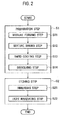
- FIG. 2 is a flowchart for explaining the method for producing silicon fine particles according to the present embodiment. As shown in Fig. 2 , the method for producing silicon fine particles according to the present embodiment includes steps S1 and S2.
- Step S1 is a preparation step of preparing silicon particles.
- Step S1 includes steps S11 to S14.
- Step S11 is a step of forming a mixture from a silicon source and a carbon source.
- the silicon source that is, a silicon-containing raw material, a liquid silicon source and a solid silicon source can be used together. Note that at least one liquid silicon source must be selected as the silicon source.
- liquid silicon source polymers of tetraalkoxy silanes and alkoxy silanes (mono-, di-, tri-, tetra-) are used.
- alkoxy silanes tetraalkoxy silanes are preferably used. Specific examples thereof include methoxysilane, ethoxysilane, propoxysilane, butoxysilane, and the like. From the view of handling, ethoxysilane is preferable.
- the polymers of tetraalkoxy silanes include liquid silicon sources of low molecular weight polymers (oligomers) having a degree of polymerization of approximately 2 to 15 and silicic acid polymers having a higher degree of polymerization.
- Examples of the solid silicon source usable together with these liquid silicon sources include silicon oxides.
- Examples of the silicon oxides include, besides SiO, silica sols (colloidal ultrafine silica-containing solution containing an OH group and an alkoxy group therein), silicon dioxide (silica gel, fine silica, quartz powder), and the like.
- tetraethoxysilane oligomers tetraethoxysilane oligomers, mixtures of tetraethoxysilane oligomer and fine powder silica, and the like are preferable from the viewpoint of homogeneity and handling.
- the initial impurity content is preferably 20 ppm or less, further preferably 5 ppm or less.
- examples of the impurity include heavy metal elements such as Fe, Ni, Cu, Cr, V, and W, alkali metal elements such as Li, Na, and K, alkaline earth or amphoteric metal elements such as Be, Mg, Ca, B, Al, and Ga, and the like.
- the carbon source that is, a carbon-containing raw material, is synthesized using a catalyst not containing an impurity element, and may be a monomer, an oligomer, and a polymer composed of any single or two or more organic compounds curable by heating and/or with the catalyst, or through polymerization or cross-linking with a crosslinker.
- the carbon-containing raw material include curable resins such as phenolic resins, furan resins, urea resins, epoxy resins, unsaturated polyester resins, polyimide resins, and polyurethane resins synthesized using a catalyst not containing an impurity element.
- curable resins such as phenolic resins, furan resins, urea resins, epoxy resins, unsaturated polyester resins, polyimide resins, and polyurethane resins synthesized using a catalyst not containing an impurity element.
- resol-type or novolac-type phenolic resins which have a high residual carbon ratio and an excellent workability are preferable.
- the resol-type phenolic resins useful in the present embodiment are produced by reacting monovalent or divalent phenols such as phenol, cresol, xylenol, resorcin, or bisphenol A with aldehydes such as formaldehyde, acetaldehyde, or benzaldehyde in the presence of a catalyst not containing an impurity element (specifically, ammonia or an organic amine).
- monovalent or divalent phenols such as phenol, cresol, xylenol, resorcin, or bisphenol A
- aldehydes such as formaldehyde, acetaldehyde, or benzaldehyde
- a catalyst not containing an impurity element specifically, ammonia or an organic amine
- the organic amine used as the catalyst may be any of primary, secondary, and tertiary amines.
- As the organic amine it is possible to use dimethylamine, trimethylamine, diethylamine, triethylamine, dimethylmonoethanolamine, monomethyldiethanolamine, N-methylaniline, pyridine, morpholine, and the like.
- the novolac-type phenolic resins useful in the present embodiment can be produced by mixing monovalent or divalent phenols and aldehydes as described above for reaction using an acid (specifically, hydrochloric acid, sulfuric acid, p-toluenesulfonic acid, oxalic acid, or the like) not containing an impurity element as a catalyst.
- an acid specifically, hydrochloric acid, sulfuric acid, p-toluenesulfonic acid, oxalic acid, or the like
- a novolac-type phenolic resin For the production of a novolac-type phenolic resin also, conventionally known methods can be employed. Specifically, 0.5 to 0.9 moles of the aldehydes and 0.02 to 0.2 moles of an inorganic acid or organic acid not containing an impurity element are added to one mole of the phenol, followed by heating to 60 to 100°C.
- step S11 to the raw material mixture in which the silicon-containing raw material and the carbon-containing raw material are mixed, a crosslinker or a catalyst for polymerization or cross-linking is added as necessary.
- the resultant is dissolved in a solvent.
- a polymerization or cross-linking reaction takes place to form the mixture.
- the raw material mixture is heated at approximately 150°C. Thereby, the mixture is dried.
- the Si/C ratio is preferably 0.5 to 3.0.
- Step S12 is a step of baking the mixture obtained in step S11 in an inert gas atmosphere.
- the mixture is housed in the container W.
- the heater 10a and the heater 10b the mixture is carbonized and silicated by heating and baking in an inert gas atmosphere. Thereby, a gas containing carbon and silicon is generated. Specifically, silicon monoxide (SiO) is produced as shown in the following formula (1).
- the inert gas atmosphere is a non-oxidizing atmosphere.
- the inert gas includes, for example, vacuum, nitrogen, helium or argon.
- Step S13 is a step of rapidly cooling the gas generated by baking the mixture to obtain a composite powder including the silicon particles.
- the blower 23 is actuated. Then, the generated gas is drawn from the inside of the heating enclosure 2 by argon gas stream through the suction pipe 21. Since the outside of the insulator 12 is maintained at room temperature, the generated gas is rapidly cooled to room temperature. Subsequently, a composite powder coated with silicon oxide is obtained from the generated gas. Specifically, by cooling at a temperature below 1600°C, the composite powder including silicon particles is obtained as shown in the following formula (2).
- the composite powder includes not only Si and SiO 2 but also SiO.
- the obtained composite powder was collected into the dust collector 22.
- the argon stream is sent into the heating enclosure 2 through the supply pipe 24.
- Step S14 is a step of immersing the composite powder into a solution for dissolving silicon oxide to obtain silicon particles.
- the collected composite powder is immersed into a solvent.
- the solvent include methanol and ethanol.
- an acid for dissolving silicon oxide is added to the solvent in which the composite powder is immersed.
- silicon oxide coating the silicon particles is dissolved, and silicon particles are obtained.
- An example of the acid includes hydrogen fluoride (HF).
- step S14 not all the silicon oxide coating the silicon particles need to be dissolved.
- the silicon particle may be partially coated with silicon oxide.
- step S2 is performed.
- Step S2 is an etching step of immersing the silicon particles into an etching solution. As shown in Fig. 2 , step S2 includes steps S21 and S22.
- Step S21 is a step of immersing the silicon particles into an etching solution.
- the silicon particles prepared in step S1 are immersed into an etching solution.
- the etching solution should be a solution capable of etching silicon fine particles.
- the etching solution include a hydrogen fluoride solution and a hot alkaline solution.
- An example of the alkaline solution includes a potassium hydroxide solution. Since a hydrogen fluoride solution is capable of efficiently etching silicon particles, the etching solution preferably contains hydrogen fluoride.
- an oxidant may be added as necessary. Examples of the oxidant include nitric acid (HNO 3 ) and hydrogen peroxide (H 2 O 2 ).
- a slightly polar solvent for example, 2-propanol
- Step S22 is a step of irradiating the silicon particles immersed in the etching solution with light having a larger energy than a band gap energy of the silicon particles.
- the band gap energy of the silicon particles varies, depending on the particle diameter of the silicon particles.
- the irradiation light and the etching time need to be adjusted as appropriate in accordance with silicon fine particles to be produced to have a desired particle diameter.
- the band gap energy of the silicon particles can be calculated based on the following formula (3).
- [Mathematical formula 1] E E g + ⁇ 2 ⁇ ⁇ 2 2 ⁇ ⁇ ⁇ 2 ⁇ R 2
- E represents a band gap energy of silicon having a particle diameter R.
- Eg represents a band gap energy of bulk silicon.
- E g is 1.2 eV.
- ⁇ represents a value obtained by dividing the Planck constant by 2 ⁇ .
- ⁇ represents a reduced mass. Specifically, ⁇ is 0.015 m e where m e is an electron rest mass.
- the band gap energy of the silicon particles obtained according to step S1 is calculated.
- the silicon particles immersed in the etching solution are irradiated with light having a larger energy than the calculated band gap energy of the silicon particles.
- the energy of the irradiation light may be calculated by assigning a desired particle diameter of silicon fine particles to R in the formula (3).
- the silicon particles are irradiated with the light having the calculated energy.
- the energy of the irradiation light can be adjusted by the wavelength of light.
- the irradiation light is preferably monochromatic light that has only a certain wavelength. This is because it makes it easy to control the particle diameter in comparison with light having multiple wavelengths.
- the light irradiation increases the temperature of the etching solution.
- the increased temperature increases the etching speed.
- a particle diameter-controlling effect is preferably obtained only by light irradiation while suppressing the change in etching speed by temperature.
- light irradiation is preferably performed while keeping the temperature of the etching solution constant.
- the energy of the irradiation light is preferably adjusted in consideration of the light absorption properties of the substance present around the silicon particles.
- the solvent is water and the gas around the solvent is air, it is preferable to irradiate with light having an energy of 6.5 eV or smaller (wavelength of 190 nm or longer).
- the etching is proceeded while the light irradiation is being performed.
- the silicon fine particles have a desired particle diameter
- the silicon fine particles are extracted from the etching solution.
- the extracted silicon fine particles are dried as appropriate. In this manner, the silicon fine particles are obtained.
- a hydrogen atom added to the surface of the silicon fine particles during the etching may be replaced by an unsaturated hydrocarbon group.
- a method for controlling a particle diameter of silicon fine particles according to the present embodiment will be described. Note that the method for controlling a particle diameter of silicon fine particles according to the present embodiment is the same process as etching step S2 in the method for producing silicon fine particles described above.
- silicon fine particles are prepared whose particle diameter is desired to be controlled.
- the silicon fine particles described here include not only ones having a particle diameter equivalent to silicon fine particles produced by the above-described production method, but also ones with various particle diameters.
- the silicon fine particles include silicon particles in the above-described method for producing silicon fine particles.
- the silicon fine particles thus prepared are immersed into an etching solution.
- the etching solution the above-described etching solution can be used.
- the silicon fine particles immersed in the etching solution are irradiated with light having a larger energy than a band gap energy of the silicon fine particles.
- the band gap energy of the silicon fine particles can be calculated based on the formula (3) described above.
- the light having a larger energy than the calculated band gap energy is used for the irradiation.
- the energy of the light may be calculated based on the formula (3). Specifically, the energy of the light may be calculated by assigning a desired particle diameter of the silicon fine particles to R in the formula (3).
- the silicon fine particles are irradiated with light having a wavelength corresponding to the energy thus obtained.
- the light irradiation time varies, depending on conditions such as the amount of silicon fine particles and light intensity. Thus, he light irradiation time is preferably adjusted as appropriate, depending on such conductions.
- silicon fine particles having a smaller band gap energy than the energy of the irradiation light (hereinafter abbreviated appropriately as first silicon fine particles)
- the etching thereon is promoted. Accordingly, the first silicon fine particles having a large particle diameter is etched fast.
- second silicon fine particles silicon fine particles
- the light irradiation does not promote the etching. Accordingly, the second silicon fine particles having a small particle diameter is etched slowly in comparison with the first silicon fine particles.
- the particle diameter of the silicon fine particles can be controlled.
- silicon particles are prepared in step S1.
- the silicon particles are not necessarily limited thereto.
- the silicon particles may be prepared through purchase of commercially-available silicon particles.
- the energy of irradiation light does not necessarily have to be calculated based on the formula (3) described above.
- a mixture solution including 620 g of ethyl silicate as the silicon source, 288 g of a phenolic resin as the carbon source, and 92 g (35 wt%) of an aqueous solution of maleic acid as the polymerization catalyst was heated at 150°C and solidified.
- the resultant mixture was carbonized in a nitrogen atmosphere at 900°C for 1 hour.
- the obtained carbide was heated in an argon atmosphere at 1600°C.
- a reaction gas generated during the heating at 1600°C was transferred to the outside of the heating enclosure 2 using the aspirator 20 and an argon gas as a carrier gas, followed by rapid cooling to obtain a composite powder.
- the hydrogen fluoride solution was irradiated with monochromatic light having a wavelength of 365 nm (Example 1), 470 nm (Example 2), or 525 nm (Example 3).
- the irradiated time was 40 hours.
- the resulting hydrogen fluoride solution thus irradiated was filtered with a membrane filter as described above. Thereby, a filtrate containing silicon fine particles was obtained. The filtrate was dried, and the resultant silicon fine particles were observed by TEM.
- the silicon particles contained in the residue on the membrane filter were also observed by TEM. In other words, before the etching, the silicon particles were observed by TEM.
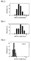
- Figs. 3 to 7 and Table 1 show the result.
- Fig. 3 is a graph showing a particle size distribution in Comparative Example 1.
- Fig. 4 is a graph showing a particle size distribution in Comparative Example 2.
- Fig. 5 is a graph showing a particle size distribution in Example 1.
- Fig. 6 is a graph showing a particle size distribution in Example 2.
- Fig. 7 is a graph showing a particle size distribution in Example 3.
- the vertical axes in Figs. 3 to 7 indicate the frequency (%), and the horizontal axes in Figs.
- the ranges of the particle size distribution of the silicon fine particles in Examples 1 to 3 were narrower than those in Comparative Example 2.
- the particle diameter of the silicon particles was from 4 nm to 11 nm.
- the particle diameter of the silicon fine particles (silicon particles) was from 4 nm to 11 nm.
- the particle diameter of the silicon fine particles was from 2 nm to 5 nm.
- the particle diameter of the silicon fine particles was from 2 nm to 6 nm.
- the particle diameter of the silicon fine particles was from 2 nm to 8 nm. This revealed that etching by light irradiation produces silicon fine particles having a uniform particle diameter in comparison to etching without light irradiation.
- Fig. 8 is a graph showing a relationship between the energy of irradiation light and the particle diameter of silicon fine particles.
- the vertical axis in Fig. 8 indicates the energy of irradiation light
- the horizontal axis in Fig. 8 indicates the reciprocal of the square of an average particle diameter of the obtained silicon fine particles.
- the straight line shown in Fig. 8 is a straight line obtained based on the formula (3).
- the black circles plotted in Fig. 8 are data obtained from the above experiments.
- the method for producing silicon fine particles according to the present embodiment includes: a preparation step of preparing silicon particles; and an etching step of immersing the silicon particles into an etching solution.
- the silicon particles immersed in the etching solution are irradiated with light having a larger energy than a band gap energy of the silicon particles.
- silicon particles When silicon particles are irradiated with light having a larger energy than the band gap energy (hereinafter abbreviated appropriately as first silicon particles), electron-hole pairs are generated inside the first silicon particles. In this event, some interatomic bonds inside or on the surface of the first silicon particles are weakened. This promotes a reaction between the first silicon particles and hydrogen fluoride. As a result, the etching on the first silicon particles is promoted.
- the smaller the particle diameter of silicon particles the larger the band gap energy of the silicon particles. Accordingly, silicon particles having a larger band gap energy than the energy of the irradiation light (hereinafter abbreviated appropriately as second silicon particles) do not generate electron-hole pairs. Hence, the promotion of the etching on the second silicon particles is suppressed.
- the etching on silicon particles having a large particle diameter is promoted, the etching on the silicon particles having a large particle diameter is performed fast.
- the etching produces silicon particles having a particle diameter of a larger band gap energy than the energy of irradiation light, the etching is not promoted additionally.
- silicon particles having a small particle diameter is etched slowly in comparison with silicon particles having a large particle diameter. In other words, such silicon particles are etched under the same condition with no light irradiation. As a result, the resulting silicon fine particles have a narrow particle size distribution. Thus, it is possible to efficiently produce silicon fine particles having a uniform particle diameter.
- the irradiation light is monochromatic light. This makes it easy to control the particle diameter in comparison with light having multiple wavelengths.
- the method for producing silicon fine particles according to the present invention enables efficient production of silicon fine particles having a uniform particle diameter. Moreover, the method for controlling a particle diameter of silicon fine particles according to the present invention can control the particle diameter of silicon fine particles.
Landscapes
- Chemical & Material Sciences (AREA)
- Organic Chemistry (AREA)
- Inorganic Chemistry (AREA)
- Engineering & Computer Science (AREA)
- Mechanical Engineering (AREA)
- Silicon Compounds (AREA)
Abstract
Description
- The present invention relates to a method for producing silicon fine particles and a method for controlling a particle diameter of silicon fine particles.
- Conventionally, as a simple method for producing silicon fine particles, a method is known by which silicon fine particles are produced from a composite powder including silicon particles coated with silicon oxide (SiOx, x=1 or 2) (see, for example, Patent Document 1). The composite powder is obtained by baking a mixture including a silicon source and a carbon source in an inert atmosphere, followed by rapid cooling of a gas generated by the baking. The composite powder thus obtained is immersed into an etching solution containing hydrogen fluoride and an oxidant to etch silicon oxide and silicon particles. In this way, silicon fine particles are obtained from a composite powder. By adjusting the etching time and the etching concentration, silicon fine particles having a desired particle diameter are obtained.
-
- Patent Document 1: Japanese Patent Application Publication No.
2007-112656 - Silicon particles contained in a composite powder have various particle diameters, and silicon fine particles obtained from the composite powder have a broad particle size distribution. Even if silicon fine particles having a small particle diameter are obtained by etching, the silicon fine particles do not have a narrow particle size distribution. Thus, silicon fine particles having a uniform particle diameter have yet to be obtained efficiently because the silicon fine particles having various particle diameters include those having particle diameters which are out of a desired particle diameter.
- Moreover, a particle size distribution is different in every production. For this reason, even if an etching condition under which a large number of fine particles having a desired particle diameter were obtained were found, this is not necessarily an optimal etching condition for the subsequent production. Hence, it has been difficult to perform etching in accordance with silicon particles having the most uniform particle diameter. From this point also, silicon fine particles having a uniform particle diameter have yet to be obtained efficiently.
- Accordingly, the present invention has been made in view of such a circumstance. An object of the present invention is to provide a method for producing silicon fine particles and a method for controlling a particle diameter of silicon fine particles which enable efficient production of silicon fine particles having a uniform particle diameter.
- The present inventors have earnestly studied in order to achieve the above-described object. As a result, the present invention having the following characteristics has been completed. A characteristic of the present invention is summarized as a method for producing silicon fine particles having a smaller particle diameter than silicon particles, the method comprising: a preparation step of preparing the silicon particles; and an etching step of immersing the silicon particles into an etching solution containing hydrogen fluoride, wherein in the etching step, the silicon particles immersed in the etching solution are irradiated with light having a larger energy than a band gap energy of the silicon particles.
- According to the characteristics of the present invention, in the etching step, the silicon particles immersed in the etching solution are irradiated with the light having a larger energy than the band gap energy of the silicon particles. When the silicon particles are irradiated with an energy larger than the band gap energy of the silicon particles, electron-hole pairs are generated inside the silicon particles. The electron-hole pairs activate the silicon particles, which promotes the etching on the silicon particles.
- The smaller the particle diameter of the silicon particles, the larger the band gap energy. Accordingly, silicon particles having a larger band gap energy than the irradiation energy do not generate electron-hole pairs, which suppresses promotion of the etching.
- Hence, if silicon particles have a large particle diameter, this promotes the etching, and the etching is performed fast. Meanwhile, if silicon particles have a particle diameter of a larger band gap energy than the irradiation energy, the etching is performed slowly. In this manner, silicon fine particles having a more uniform particle diameter than heretofore are obtained. This enables efficient production of silicon fine particles having a uniform particle diameter.
- Another characteristic of the present invention is summarized as the etching solution contains hydrogen fluoride.
- Another characteristic of the present invention is summarized as the light is monochromatic light.
- Another characteristic of the present invention is summarized as the preparation step includes: a baking step of baking a mixture including a silicon source and a carbon source in an inert atmosphere; a rapid cooling step of rapidly cooling a gas generated by baking the mixture to obtain a composite powder coated with silicon oxide; and a dissolving step of immersing the composite powder into a solution for dissolving the silicon oxide to obtain silicon particles.
- A characteristic according to a method for producing silicon fine particles of the present invention is summarized as the method comprising the steps of immersing silicon particles into an etching solution; and irradiating the silicon fine particles immersed in the etching solution with light having a larger energy than a band gap energy of the silicon fine particles.
-
- [
Fig. 1] Fig. 1 is a schematic configuration diagram of aproduction apparatus 1 according to the present embodiment used for producing silicon fine particles. - [
Fig. 2] Fig. 2 is a flowchart for explaining a method for producing silicon fine particles according to the present embodiment. - [
Fig. 3] Fig. 3 is a graph showing a particle size distribution in Comparative Example 1. - [
Fig. 4] Fig. 4 is a graph showing a particle size distribution in Comparative Example 2. - [
Fig. 5] Fig. 5 is a graph showing a particle size distribution in Example 1. - [
Fig. 6] Fig. 6 is a graph showing a particle size distribution in Example 2. - [
Fig. 7] Fig. 7 is a graph showing a particle size distribution in Example 3. - [
Fig. 8] Fig. 8 is a graph showing a relationship between the energy of irradiation light and the particle diameter of silicon fine particles. - An example of a method for producing silicon fine particles according to the present invention will be described with reference to the drawings. Specifically, descriptions are given of (1) Schematic Configuration of
Production Apparatus 1, (2) Method for Producing Silicon Fine Particles, (3) Method for Controlling Particle Diameter of Silicon Fine Particles, (4) Other embodiments, (5) Comparative Evaluation, and (6) Operations and Effects. - In the following description of the drawings, same or similar reference signs denote same or similar elements and portions. It should be noted that the drawings are schematic and ratios of dimensions and the like are different from actual ones. Therefore, specific dimensions and the like should be determined in consideration of the following description. The drawings also include portions having different dimensional relationships and ratios from each other.
- A schematic configuration of a
production apparatus 1 according to the present embodiment used for producing silicon fine particles will be described with reference toFig. 1. Fig. 1 is a schematic configuration diagram of theproduction apparatus 1 according to the present embodiment used for producing silicon fine particles. - As shown in
Fig. 1 , theproduction apparatus 1 includes aheating enclosure 2, a stage 8, aheater 10a and aheater 10b, an insulator 12, anaspirator 20, adust collector 22, and ablower 23. Theheating enclosure 2 forms a heating atmosphere for a container W housing a mixture including a silicon source and a carbon source. Theheater 10a and theheater 10b heat the stage 8 supporting theheating enclosure 2, and the mixture housed in the container W. The insulator 12 covers theheating enclosure 2, theheater 10a, and theheater 10b. Theblower 23 sucks a reaction gas from theheating enclosure 2 through asuction pipe 21. Thedust collector 22 houses a composite powder. Theaspirator 20 has asupply pipe 24 for supplying a gas. Theaspirator 20 is capable of sucking a SiO gas while maintaining the heating and inert atmosphere in theheating enclosure 2. Theaspirator 20 is provided so that an argon gas can circulate therein. Moreover, theaspirator 20 includes anelectromagnetic valve 25 which automatically opens and closes by a pressure set. - A method for producing silicon fine particles according to the present embodiment will be described with reference to
Fig. 1 .Fig. 2 is a flowchart for explaining the method for producing silicon fine particles according to the present embodiment. As shown inFig. 2 , the method for producing silicon fine particles according to the present embodiment includes steps S1 and S2. - Step S1 is a preparation step of preparing silicon particles. Step S1 includes steps S11 to S14.
- Step S11 is a step of forming a mixture from a silicon source and a carbon source.
- As the silicon source, that is, a silicon-containing raw material, a liquid silicon source and a solid silicon source can be used together. Note that at least one liquid silicon source must be selected as the silicon source.
- As the liquid silicon source, polymers of tetraalkoxy silanes and alkoxy silanes (mono-, di-, tri-, tetra-) are used. Among the alkoxy silanes, tetraalkoxy silanes are preferably used. Specific examples thereof include methoxysilane, ethoxysilane, propoxysilane, butoxysilane, and the like. From the view of handling, ethoxysilane is preferable. Examples of the polymers of tetraalkoxy silanes include liquid silicon sources of low molecular weight polymers (oligomers) having a degree of polymerization of approximately 2 to 15 and silicic acid polymers having a higher degree of polymerization.
- Examples of the solid silicon source usable together with these liquid silicon sources include silicon oxides. Examples of the silicon oxides include, besides SiO, silica sols (colloidal ultrafine silica-containing solution containing an OH group and an alkoxy group therein), silicon dioxide (silica gel, fine silica, quartz powder), and the like.
- Among these silicon sources, tetraethoxysilane oligomers, mixtures of tetraethoxysilane oligomer and fine powder silica, and the like are preferable from the viewpoint of homogeneity and handling.
- To obtain a high-purity silicon carbide powder, a high-purity substance is preferable used as the silicon source. Specifically, the initial impurity content is preferably 20 ppm or less, further preferably 5 ppm or less.
- Note that examples of the impurity include heavy metal elements such as Fe, Ni, Cu, Cr, V, and W, alkali metal elements such as Li, Na, and K, alkaline earth or amphoteric metal elements such as Be, Mg, Ca, B, Al, and Ga, and the like.
- The carbon source, that is, a carbon-containing raw material, is synthesized using a catalyst not containing an impurity element, and may be a monomer, an oligomer, and a polymer composed of any single or two or more organic compounds curable by heating and/or with the catalyst, or through polymerization or cross-linking with a crosslinker.
- Preferable specific examples of the carbon-containing raw material include curable resins such as phenolic resins, furan resins, urea resins, epoxy resins, unsaturated polyester resins, polyimide resins, and polyurethane resins synthesized using a catalyst not containing an impurity element. Particularly, resol-type or novolac-type phenolic resins which have a high residual carbon ratio and an excellent workability are preferable.
- The resol-type phenolic resins useful in the present embodiment are produced by reacting monovalent or divalent phenols such as phenol, cresol, xylenol, resorcin, or bisphenol A with aldehydes such as formaldehyde, acetaldehyde, or benzaldehyde in the presence of a catalyst not containing an impurity element (specifically, ammonia or an organic amine).
- The organic amine used as the catalyst may be any of primary, secondary, and tertiary amines. As the organic amine, it is possible to use dimethylamine, trimethylamine, diethylamine, triethylamine, dimethylmonoethanolamine, monomethyldiethanolamine, N-methylaniline, pyridine, morpholine, and the like.
- As the method for synthesizing a resol-type phenolic resin by reacting a phenol with an aldehyde in the presence of ammonia or an organic amine, conventionally known methods can be employed, except that a different catalyst is used.
- Specifically, 1 to 3 moles of the aldehyde and 0.02 to 0.2 moles of the organic amine or ammonia are added to 1 mole of the phenol, followed by heating to 60 to 100°C.
- Meanwhile, the novolac-type phenolic resins useful in the present embodiment can be produced by mixing monovalent or divalent phenols and aldehydes as described above for reaction using an acid (specifically, hydrochloric acid, sulfuric acid, p-toluenesulfonic acid, oxalic acid, or the like) not containing an impurity element as a catalyst.
- For the production of a novolac-type phenolic resin also, conventionally known methods can be employed. Specifically, 0.5 to 0.9 moles of the aldehydes and 0.02 to 0.2 moles of an inorganic acid or organic acid not containing an impurity element are added to one mole of the phenol, followed by heating to 60 to 100°C.
- In step S11, to the raw material mixture in which the silicon-containing raw material and the carbon-containing raw material are mixed, a crosslinker or a catalyst for polymerization or cross-linking is added as necessary. The resultant is dissolved in a solvent. A polymerization or cross-linking reaction takes place to form the mixture. The raw material mixture is heated at approximately 150°C. Thereby, the mixture is dried. The Si/C ratio is preferably 0.5 to 3.0.
- Step S12 is a step of baking the mixture obtained in step S11 in an inert gas atmosphere. The mixture is housed in the container W. Using the
heater 10a and theheater 10b, the mixture is carbonized and silicated by heating and baking in an inert gas atmosphere. Thereby, a gas containing carbon and silicon is generated. Specifically, silicon monoxide (SiO) is produced as shown in the following formula (1). -
SiO2 + C → SiO + CO (1)
The inert gas atmosphere is a non-oxidizing atmosphere. The inert gas includes, for example, vacuum, nitrogen, helium or argon. - Next, step S13 is performed. Step S13 is a step of rapidly cooling the gas generated by baking the mixture to obtain a composite powder including the silicon particles. The
blower 23 is actuated. Then, the generated gas is drawn from the inside of theheating enclosure 2 by argon gas stream through thesuction pipe 21. Since the outside of the insulator 12 is maintained at room temperature, the generated gas is rapidly cooled to room temperature. Subsequently, a composite powder coated with silicon oxide is obtained from the generated gas. Specifically, by cooling at a temperature below 1600°C, the composite powder including silicon particles is obtained as shown in the following formula (2). -
2SiO → Si + SiO2 (2)
Note that since the reaction in the formula (2) does not always completely proceed, the composite powder includes not only Si and SiO2 but also SiO. In other words, the composite powder includes Si and SiOx (x=1 or 2), other than impurities. - The obtained composite powder was collected into the
dust collector 22. The argon stream is sent into theheating enclosure 2 through thesupply pipe 24. - Next, step S14 is performed. Step S14 is a step of immersing the composite powder into a solution for dissolving silicon oxide to obtain silicon particles. The collected composite powder is immersed into a solvent. Examples of the solvent include methanol and ethanol. To the solvent in which the composite powder is immersed, an acid for dissolving silicon oxide is added. Thereby, silicon oxide coating the silicon particles is dissolved, and silicon particles are obtained. An example of the acid includes hydrogen fluoride (HF).
- In step S14, not all the silicon oxide coating the silicon particles need to be dissolved. The silicon particle may be partially coated with silicon oxide.
- Next, step S2 is performed. Step S2 is an etching step of immersing the silicon particles into an etching solution. As shown in
Fig. 2 , step S2 includes steps S21 and S22. - Step S21 is a step of immersing the silicon particles into an etching solution. The silicon particles prepared in step S1 are immersed into an etching solution. The etching solution should be a solution capable of etching silicon fine particles. Examples of the etching solution include a hydrogen fluoride solution and a hot alkaline solution. An example of the alkaline solution includes a potassium hydroxide solution. Since a hydrogen fluoride solution is capable of efficiently etching silicon particles, the etching solution preferably contains hydrogen fluoride. To the etching solution, an oxidant may be added as necessary. Examples of the oxidant include nitric acid (HNO3) and hydrogen peroxide (H2O2). A slightly polar solvent (for example, 2-propanol) may be mixed with the etching solution to facilitate recovery of silicon fine particles.
- Step S22 is a step of irradiating the silicon particles immersed in the etching solution with light having a larger energy than a band gap energy of the silicon particles. The band gap energy of the silicon particles varies, depending on the particle diameter of the silicon particles. Thus, the irradiation light and the etching time need to be adjusted as appropriate in accordance with silicon fine particles to be produced to have a desired particle diameter.
- The band gap energy of the silicon particles can be calculated based on the following formula (3).
[Mathematical formula 1]
E represents a band gap energy of silicon having a particle diameter R. Eg represents a band gap energy of bulk silicon. Specifically, Eg is 1.2 eV.
represents a value obtained by dividing the Planck constant by 2π. µ represents a reduced mass. Specifically, µ is 0.015 me where me is an electron rest mass. - Based on the formula (3), the band gap energy of the silicon particles obtained according to step S1 is calculated. The silicon particles immersed in the etching solution are irradiated with light having a larger energy than the calculated band gap energy of the silicon particles.
- The energy of the irradiation light may be calculated by assigning a desired particle diameter of silicon fine particles to R in the formula (3). The silicon particles are irradiated with the light having the calculated energy. The energy of the irradiation light can be adjusted by the wavelength of light.
- The irradiation light is preferably monochromatic light that has only a certain wavelength. This is because it makes it easy to control the particle diameter in comparison with light having multiple wavelengths.
- The light irradiation increases the temperature of the etching solution. The increased temperature increases the etching speed. In order to facilitate the controlling of the particle diameter, a particle diameter-controlling effect is preferably obtained only by light irradiation while suppressing the change in etching speed by temperature. Thus, light irradiation is preferably performed while keeping the temperature of the etching solution constant.
- When the light is absorbed by a substance present around the silicon particles (for example, the solvent, a gas around the solvent, or the like), this makes it hard for the light to reach the silicon fine particles. For this reason, the energy of the irradiation light is preferably adjusted in consideration of the light absorption properties of the substance present around the silicon particles. For example, in a case where the solvent is water and the gas around the solvent is air, it is preferable to irradiate with light having an energy of 6.5 eV or smaller (wavelength of 190 nm or longer).
- The etching is proceeded while the light irradiation is being performed. When the silicon fine particles have a desired particle diameter, the silicon fine particles are extracted from the etching solution. The extracted silicon fine particles are dried as appropriate. In this manner, the silicon fine particles are obtained.
- Note that a hydrogen atom added to the surface of the silicon fine particles during the etching may be replaced by an unsaturated hydrocarbon group.
- A method for controlling a particle diameter of silicon fine particles according to the present embodiment will be described. Note that the method for controlling a particle diameter of silicon fine particles according to the present embodiment is the same process as etching step S2 in the method for producing silicon fine particles described above.
- First, silicon fine particles are prepared whose particle diameter is desired to be controlled. The silicon fine particles described here include not only ones having a particle diameter equivalent to silicon fine particles produced by the above-described production method, but also ones with various particle diameters. Thus, for example, the silicon fine particles include silicon particles in the above-described method for producing silicon fine particles.
- Next, the silicon fine particles thus prepared are immersed into an etching solution. As the etching solution, the above-described etching solution can be used.
- The silicon fine particles immersed in the etching solution are irradiated with light having a larger energy than a band gap energy of the silicon fine particles. The band gap energy of the silicon fine particles can be calculated based on the formula (3) described above. The light having a larger energy than the calculated band gap energy is used for the irradiation. The energy of the light may be calculated based on the formula (3). Specifically, the energy of the light may be calculated by assigning a desired particle diameter of the silicon fine particles to R in the formula (3). The silicon fine particles are irradiated with light having a wavelength corresponding to the energy thus obtained.
- The light irradiation time varies, depending on conditions such as the amount of silicon fine particles and light intensity. Thus, he light irradiation time is preferably adjusted as appropriate, depending on such conductions.
- The smaller the particle diameter of the silicon fine particles, the larger the band gap energy. In a case of silicon fine particles having a smaller band gap energy than the energy of the irradiation light (hereinafter abbreviated appropriately as first silicon fine particles), the etching thereon is promoted. Accordingly, the first silicon fine particles having a large particle diameter is etched fast. Meanwhile, in a case of silicon fine particles having a larger band gap energy than the energy of the irradiation light (hereinafter abbreviated appropriately as second silicon fine particles), the light irradiation does not promote the etching. Accordingly, the second silicon fine particles having a small particle diameter is etched slowly in comparison with the first silicon fine particles.
- By changing the energy of irradiation light, the particle diameter of the silicon fine particles can be controlled.
- The present invention has been described by the embodiments above. However, it should not be understood that the description and drawings which constitute part of this disclosure limit the present invention. From this disclosure, various alternative embodiments, examples, and operation techniques will be easily found by those skilled in the art. The present invention includes various embodiment not described herein.
- For example, in the method for producing silicon fine particles according to the present embodiment, silicon particles are prepared in step S1. However, the silicon particles are not necessarily limited thereto. The silicon particles may be prepared through purchase of commercially-available silicon particles.
- Moreover, the energy of irradiation light does not necessarily have to be calculated based on the formula (3) described above.
- Accordingly, the technical scope of the present invention should be determined only by the matters to define the invention in the scope of claims regarded as appropriate based on the description herein.
- To examine the effects of the present invention, the following experiments were conducted. Note that these Examples do not limit the present invention at all.
- A mixture solution including 620 g of ethyl silicate as the silicon source, 288 g of a phenolic resin as the carbon source, and 92 g (35 wt%) of an aqueous solution of maleic acid as the polymerization catalyst was heated at 150°C and solidified. Next, the resultant mixture was carbonized in a nitrogen atmosphere at 900°C for 1 hour. The obtained carbide was heated in an argon atmosphere at 1600°C.
- A reaction gas generated during the heating at 1600°C was transferred to the outside of the
heating enclosure 2 using theaspirator 20 and an argon gas as a carrier gas, followed by rapid cooling to obtain a composite powder. - Into 4 ml of methanol, 0.06 g of the obtained composite powder was immersed. To this solution, 5 ml of 46% hydrofluoric acid (HF) was added. The solution was mixed and filtered with a membrane filter. The residue (containing silicon particles) on the membrane filter was dispersed in propanol. To this solution, 0.05 ml of 46% hydrofluoric acid (HF) was added.
- While the resulting hydrogen fluoride solution was being stirred with a stirrer, irradiation was performed with monochromatic light. The hydrogen fluoride solution was irradiated with monochromatic light having a wavelength of 365 nm (Example 1), 470 nm (Example 2), or 525 nm (Example 3). The irradiated time was 40 hours.
- The resulting hydrogen fluoride solution thus irradiated was filtered with a membrane filter as described above. Thereby, a filtrate containing silicon fine particles was obtained. The filtrate was dried, and the resultant silicon fine particles were observed by TEM.
- In addition, before hydrofluoric acid was added, the silicon particles contained in the residue on the membrane filter (Comparative Example 1) were also observed by TEM. In other words, before the etching, the silicon particles were observed by TEM.
- Additionally, silicon fine particles were obtained under the same conditions as those of Examples above except that no irradiation with the monochromatic light was performed (Comparative Example 2). The silicon fine particles were observed by TEM.
Figs. 3 to 7 and Table 1 show the result.Fig. 3 is a graph showing a particle size distribution in Comparative Example 1.Fig. 4 is a graph showing a particle size distribution in Comparative Example 2.Fig. 5 is a graph showing a particle size distribution in Example 1.Fig. 6 is a graph showing a particle size distribution in Example 2.Fig. 7 is a graph showing a particle size distribution in Example 3. The vertical axes inFigs. 3 to 7 indicate the frequency (%), and the horizontal axes inFigs. 3 to 7 indicate the particle diameter (nm) of the particles.[Table 1] Wavelength (nm) Average particle diameter (nm) Comparative Example 1 - 6.25 Comparative Example 2 - 6.31 Example 1 365 3.4 Example 2 470 3.9 Example 3 525 4.5 - As a result of the TEM observations, the ranges of the particle size distribution of the silicon fine particles in Examples 1 to 3 were narrower than those in Comparative Example 2. Specifically, in Comparative Example 1, the particle diameter of the silicon particles was from 4 nm to 11 nm. In Comparative Example 2, the particle diameter of the silicon fine particles (silicon particles) was from 4 nm to 11 nm. In Example 1, the particle diameter of the silicon fine particles was from 2 nm to 5 nm. In Example 2, the particle diameter of the silicon fine particles was from 2 nm to 6 nm. In Example 3, the particle diameter of the silicon fine particles was from 2 nm to 8 nm. This revealed that etching by light irradiation produces silicon fine particles having a uniform particle diameter in comparison to etching without light irradiation.
- Further, it was revealed as shown in Table 1 that irradiation with light of a short wavelength, that is, light having a high energy produces silicon fine particles having a small particle diameter. Thus, it was revealed that by changing the energy of irradiation light, the particle diameter of silicon fine particles can be controlled. Note that it can be seen from Comparative Examples 1 and 2 that the particle diameter hardly changes when light irradiation is not performed. An etching solution capable of etching silicon particles only when the silicon particles are irradiated with light is used preferably in terms of controlling the particle diameter of silicon fine particles.
- In addition, the reason why the particle diameter in Comparative Example 2 was slightly larger than that in Comparative Example 1 is presumably that the stirring of the hydrogen fluoride solution with the stirrer caused fusion of some silicon particles (silicon fine particles).
-
Fig. 8 is a graph showing a relationship between the energy of irradiation light and the particle diameter of silicon fine particles. The vertical axis inFig. 8 indicates the energy of irradiation light, and the horizontal axis inFig. 8 indicates the reciprocal of the square of an average particle diameter of the obtained silicon fine particles. The straight line shown inFig. 8 is a straight line obtained based on the formula (3). The black circles plotted inFig. 8 are data obtained from the above experiments. - It can be seen as shown in
Fig. 8 that the plotted point of each data is located on the straight line of the formula (3) or in the vicinity of the straight line of the formula (3). Thus, it was revealed that irradiating silicon particles with light having an energy calculated using the formula (3) produces silicon fine particles having a desired particle diameter. In other words, it was revealed that the particle diameter of silicon fine particles can be controlled. - The method for producing silicon fine particles according to the present embodiment includes: a preparation step of preparing silicon particles; and an etching step of immersing the silicon particles into an etching solution. In the etching step, the silicon particles immersed in the etching solution are irradiated with light having a larger energy than a band gap energy of the silicon particles.
- When silicon particles are irradiated with light having a larger energy than the band gap energy (hereinafter abbreviated appropriately as first silicon particles), electron-hole pairs are generated inside the first silicon particles. In this event, some interatomic bonds inside or on the surface of the first silicon particles are weakened. This promotes a reaction between the first silicon particles and hydrogen fluoride. As a result, the etching on the first silicon particles is promoted. The smaller the particle diameter of silicon particles, the larger the band gap energy of the silicon particles. Accordingly, silicon particles having a larger band gap energy than the energy of the irradiation light (hereinafter abbreviated appropriately as second silicon particles) do not generate electron-hole pairs. Hence, the promotion of the etching on the second silicon particles is suppressed.
- Since the etching on silicon particles having a large particle diameter is promoted, the etching on the silicon particles having a large particle diameter is performed fast. When the etching produces silicon particles having a particle diameter of a larger band gap energy than the energy of irradiation light, the etching is not promoted additionally. Thus, silicon particles having a small particle diameter is etched slowly in comparison with silicon particles having a large particle diameter. In other words, such silicon particles are etched under the same condition with no light irradiation. As a result, the resulting silicon fine particles have a narrow particle size distribution. Thus, it is possible to efficiently produce silicon fine particles having a uniform particle diameter.
- The higher the energy of irradiation light, the more electron-hole pairs generated inside silicon particles having a larger band gap energy (i.e., silicon particles having a smaller particle diameter). This means that the higher the energy of irradiation light, the'longer the promotion of the etching lasts until the particles have a small diameter. Thus, by changing the energy of irradiation light, the particle diameter of the silicon fine particles can be controlled.
- In the method for producing silicon fine particles according to the present embodiment, the irradiation light is monochromatic light. This makes it easy to control the particle diameter in comparison with light having multiple wavelengths.
- Note that the entire content of Japanese Patent Application No.
2010-203528 (filed on September 10, 2010 - The method for producing silicon fine particles according to the present invention enables efficient production of silicon fine particles having a uniform particle diameter. Moreover, the method for controlling a particle diameter of silicon fine particles according to the present invention can control the particle diameter of silicon fine particles.
Claims (5)
- A method for producing silicon fine particles having a smaller particle diameter than silicon particles, the method comprising:a preparation step of preparing the silicon particles; andan etching step of immersing the silicon particles into an etching solution, whereinin the etching step, the silicon particles immersed in the etching solution are irradiated with light having a larger energy than a band gap energy of the silicon particles.
- The method for producing silicon fine particles according to claim 1, wherein the etching solution contains hydrogen fluoride.
- The method for producing silicon fine particles according to any one of claims 1 and 2, wherein the light is monochromatic light.
- The method for producing silicon fine particles according to any one of claims 1 to 3, wherein
the preparation step includes:a baking step of baking a mixture including a silicon source and a carbon source in an inert atmosphere;a rapid cooling step of rapidly cooling a gas generated by baking the mixture to obtain a composite powder coated with silicon oxide; anda dissolving step of immersing the composite powder into a solution for dissolving the silicon oxide to obtain silicon particles. - A particle diameter-controlling method for controlling a particle diameter of silicon fine particles, the method comprising the steps of:immersing silicon particles into an etching solution; andirradiating the silicon fine particles immersed in the etching solution with light having a larger energy than a band gap energy of the silicon fine particles.
Applications Claiming Priority (2)
| Application Number | Priority Date | Filing Date | Title |
|---|---|---|---|
| JP2010203528 | 2010-09-10 | ||
| PCT/JP2011/070636 WO2012033203A1 (en) | 2010-09-10 | 2011-09-09 | Method of producing silicon fine particles and method of controlling particle size of silicon fine particles |
Publications (2)
| Publication Number | Publication Date |
|---|---|
| EP2615063A1 true EP2615063A1 (en) | 2013-07-17 |
| EP2615063A4 EP2615063A4 (en) | 2015-11-11 |
Family
ID=45810798
Family Applications (1)
| Application Number | Title | Priority Date | Filing Date |
|---|---|---|---|
| EP11823677.7A Withdrawn EP2615063A4 (en) | 2010-09-10 | 2011-09-09 | Method of producing silicon fine particles and method of controlling particle size of silicon fine particles |
Country Status (7)
| Country | Link |
|---|---|
| US (1) | US8673168B2 (en) |
| EP (1) | EP2615063A4 (en) |
| JP (1) | JP5010058B1 (en) |
| KR (1) | KR101397237B1 (en) |
| CN (1) | CN103097292B (en) |
| AU (1) | AU2011299789B2 (en) |
| WO (1) | WO2012033203A1 (en) |
Families Citing this family (2)
| Publication number | Priority date | Publication date | Assignee | Title |
|---|---|---|---|---|
| JP2021042112A (en) * | 2019-09-13 | 2021-03-18 | 株式会社トクヤマ | Method for producing purified silicon fine particles |
| KR102391903B1 (en) | 2020-02-07 | 2022-04-28 | 한국과학기술연구원 | Process of preparing high purity methanol precursor or methanol or methyl ester from methane |
Family Cites Families (13)
| Publication number | Priority date | Publication date | Assignee | Title |
|---|---|---|---|---|
| US5069740A (en) * | 1984-09-04 | 1991-12-03 | Texas Instruments Incorporated | Production of semiconductor grade silicon spheres from metallurgical grade silicon particles |
| JPS61215211A (en) * | 1985-03-18 | 1986-09-25 | Nippon Telegr & Teleph Corp <Ntt> | Collection of ultrafine powder of silicon |
| US6794265B2 (en) * | 2001-08-02 | 2004-09-21 | Ultradots, Inc. | Methods of forming quantum dots of Group IV semiconductor materials |
| JP2006070089A (en) * | 2004-08-31 | 2006-03-16 | Tokyo Denki Univ | Environmentally safe nanosilicon solution, nanosilicon powder and method for producing the same |
| WO2007037787A1 (en) * | 2005-05-09 | 2007-04-05 | Vesta Research, Ltd. | Porous silicon particles |
| JP4980603B2 (en) * | 2005-10-19 | 2012-07-18 | 株式会社ブリヂストン | Method for producing silicon fine particles |
| WO2007086225A1 (en) * | 2006-01-27 | 2007-08-02 | Konica Minolta Medical & Graphic, Inc. | Process for producing nanoparticle |
| US7833428B2 (en) * | 2006-06-16 | 2010-11-16 | Packer Engineering, Inc. | Processes and apparatuses for producing porous materials |
| JP2008019114A (en) * | 2006-07-11 | 2008-01-31 | Catalysts & Chem Ind Co Ltd | Method for producing silicon fine particles |
| JP2008019115A (en) | 2006-07-11 | 2008-01-31 | Catalysts & Chem Ind Co Ltd | Method for producing silicon fine particles |
| WO2009017205A1 (en) * | 2007-08-01 | 2009-02-05 | Bridgestone Corporation | Method for manufacturing silicon fine particle coating agent |
| JP5563755B2 (en) * | 2007-11-05 | 2014-07-30 | 株式会社ブリヂストン | Method for producing silicon fine particle light emitter |
| JP5152039B2 (en) | 2009-03-03 | 2013-02-27 | トヨタ自動車株式会社 | Shift control device |
-
2011
- 2011-09-09 AU AU2011299789A patent/AU2011299789B2/en not_active Ceased
- 2011-09-09 WO PCT/JP2011/070636 patent/WO2012033203A1/en not_active Ceased
- 2011-09-09 JP JP2012509796A patent/JP5010058B1/en not_active Expired - Fee Related
- 2011-09-09 US US13/821,603 patent/US8673168B2/en not_active Expired - Fee Related
- 2011-09-09 CN CN201180043160.9A patent/CN103097292B/en not_active Expired - Fee Related
- 2011-09-09 EP EP11823677.7A patent/EP2615063A4/en not_active Withdrawn
- 2011-09-09 KR KR1020137005955A patent/KR101397237B1/en not_active Expired - Fee Related
Also Published As
| Publication number | Publication date |
|---|---|
| JPWO2012033203A1 (en) | 2014-01-20 |
| AU2011299789B2 (en) | 2014-05-08 |
| US8673168B2 (en) | 2014-03-18 |
| AU2011299789A1 (en) | 2013-03-28 |
| US20130168356A1 (en) | 2013-07-04 |
| CN103097292B (en) | 2015-04-15 |
| JP5010058B1 (en) | 2012-08-29 |
| KR101397237B1 (en) | 2014-05-20 |
| KR20130041316A (en) | 2013-04-24 |
| WO2012033203A1 (en) | 2012-03-15 |
| EP2615063A4 (en) | 2015-11-11 |
| CN103097292A (en) | 2013-05-08 |
Similar Documents
| Publication | Publication Date | Title |
|---|---|---|
| TWI741116B (en) | Silica particle dispersion liquid and its manufacturing method | |
| US5318761A (en) | Process for preparing silicon carbide powder for use in semiconductor equipment | |
| JP2019116396A (en) | Silica-based particle dispersion and production method thereof | |
| US8673168B2 (en) | Method for producing silicon fine particles and method for controlling particle diameter of silicon fine particles | |
| US20150210616A1 (en) | Preparation method for edge-fluorinated graphite via mechanic-chemical process | |
| US9085731B2 (en) | Methods for producing light-emitting body containing silicon fine particles and light-emitting silicon fine particles | |
| JP4791697B2 (en) | Method for producing silicon particles | |
| JP2007112656A (en) | Method for producing silicon fine particle | |
| JP2012099650A (en) | Manufacturing method for solar cell module and solar cell module | |
| JP6305281B2 (en) | Silica fired body and silica dispersion | |
| EP2607311A1 (en) | Method for producing silicon microparticles | |
| US20150004090A1 (en) | Method and apparatus for producing silicon fine particles | |
| JP5563755B2 (en) | Method for producing silicon fine particle light emitter | |
| WO2012060418A1 (en) | Method for manufacturing resin material, resin material, method for manufacturing solar cell module, and solar cell module | |
| US20150307775A1 (en) | Method of preparing a composite article and composite article | |
| JP5261230B2 (en) | Method for producing silicon fine particle light emitter | |
| JP2013230946A (en) | Method of manufacturing silicon fine particle | |
| JP2008050201A (en) | Method for producing silicon carbide powder, and silicon carbide powder | |
| JP2012097196A (en) | Method for manufacturing resin material, and resin material | |
| JP2014156364A (en) | Method for producing fine silicon carbide particle | |
| JP2014156363A (en) | Method for producing fine silicon particle | |
| JP2014156361A (en) | Method for producing fine silicon carbide particle |
Legal Events
| Date | Code | Title | Description |
|---|---|---|---|
| PUAI | Public reference made under article 153(3) epc to a published international application that has entered the european phase |
Free format text: ORIGINAL CODE: 0009012 |
|
| 17P | Request for examination filed |
Effective date: 20130312 |
|
| AK | Designated contracting states |
Kind code of ref document: A1 Designated state(s): AL AT BE BG CH CY CZ DE DK EE ES FI FR GB GR HR HU IE IS IT LI LT LU LV MC MK MT NL NO PL PT RO RS SE SI SK SM TR |
|
| DAX | Request for extension of the european patent (deleted) | ||
| RA4 | Supplementary search report drawn up and despatched (corrected) |
Effective date: 20151014 |
|
| RIC1 | Information provided on ipc code assigned before grant |
Ipc: C01B 33/037 20060101ALI20151008BHEP Ipc: C01B 33/025 20060101AFI20151008BHEP |
|
| STAA | Information on the status of an ep patent application or granted ep patent |
Free format text: STATUS: THE APPLICATION IS DEEMED TO BE WITHDRAWN |
|
| 18D | Application deemed to be withdrawn |
Effective date: 20160510 |