EP2615058B1 - Hydrogen generator and fuel cell power generator - Google Patents
Hydrogen generator and fuel cell power generator Download PDFInfo
- Publication number
- EP2615058B1 EP2615058B1 EP13001895.5A EP13001895A EP2615058B1 EP 2615058 B1 EP2615058 B1 EP 2615058B1 EP 13001895 A EP13001895 A EP 13001895A EP 2615058 B1 EP2615058 B1 EP 2615058B1
- Authority
- EP
- European Patent Office
- Prior art keywords
- catalyst layer
- water
- gas
- evaporation unit
- water evaporation
- Prior art date
- Legal status (The legal status is an assumption and is not a legal conclusion. Google has not performed a legal analysis and makes no representation as to the accuracy of the status listed.)
- Active
Links
Images


Classifications
-
- H—ELECTRICITY
- H01—ELECTRIC ELEMENTS
- H01M—PROCESSES OR MEANS, e.g. BATTERIES, FOR THE DIRECT CONVERSION OF CHEMICAL ENERGY INTO ELECTRICAL ENERGY
- H01M8/00—Fuel cells; Manufacture thereof
- H01M8/06—Combination of fuel cells with means for production of reactants or for treatment of residues
- H01M8/0606—Combination of fuel cells with means for production of reactants or for treatment of residues with means for production of gaseous reactants
- H01M8/0612—Combination of fuel cells with means for production of reactants or for treatment of residues with means for production of gaseous reactants from carbon-containing material
-
- B—PERFORMING OPERATIONS; TRANSPORTING
- B01—PHYSICAL OR CHEMICAL PROCESSES OR APPARATUS IN GENERAL
- B01J—CHEMICAL OR PHYSICAL PROCESSES, e.g. CATALYSIS OR COLLOID CHEMISTRY; THEIR RELEVANT APPARATUS
- B01J8/00—Chemical or physical processes in general, conducted in the presence of fluids and solid particles; Apparatus for such processes
- B01J8/02—Chemical or physical processes in general, conducted in the presence of fluids and solid particles; Apparatus for such processes with stationary particles, e.g. in fixed beds
- B01J8/04—Chemical or physical processes in general, conducted in the presence of fluids and solid particles; Apparatus for such processes with stationary particles, e.g. in fixed beds the fluid passing successively through two or more beds
- B01J8/0446—Chemical or physical processes in general, conducted in the presence of fluids and solid particles; Apparatus for such processes with stationary particles, e.g. in fixed beds the fluid passing successively through two or more beds the flow within the beds being predominantly vertical
- B01J8/0461—Chemical or physical processes in general, conducted in the presence of fluids and solid particles; Apparatus for such processes with stationary particles, e.g. in fixed beds the fluid passing successively through two or more beds the flow within the beds being predominantly vertical in two or more cylindrical annular shaped beds
- B01J8/0469—Chemical or physical processes in general, conducted in the presence of fluids and solid particles; Apparatus for such processes with stationary particles, e.g. in fixed beds the fluid passing successively through two or more beds the flow within the beds being predominantly vertical in two or more cylindrical annular shaped beds the beds being superimposed one above the other
-
- B—PERFORMING OPERATIONS; TRANSPORTING
- B01—PHYSICAL OR CHEMICAL PROCESSES OR APPARATUS IN GENERAL
- B01J—CHEMICAL OR PHYSICAL PROCESSES, e.g. CATALYSIS OR COLLOID CHEMISTRY; THEIR RELEVANT APPARATUS
- B01J8/00—Chemical or physical processes in general, conducted in the presence of fluids and solid particles; Apparatus for such processes
- B01J8/02—Chemical or physical processes in general, conducted in the presence of fluids and solid particles; Apparatus for such processes with stationary particles, e.g. in fixed beds
- B01J8/04—Chemical or physical processes in general, conducted in the presence of fluids and solid particles; Apparatus for such processes with stationary particles, e.g. in fixed beds the fluid passing successively through two or more beds
- B01J8/0492—Feeding reactive fluids
-
- B—PERFORMING OPERATIONS; TRANSPORTING
- B01—PHYSICAL OR CHEMICAL PROCESSES OR APPARATUS IN GENERAL
- B01J—CHEMICAL OR PHYSICAL PROCESSES, e.g. CATALYSIS OR COLLOID CHEMISTRY; THEIR RELEVANT APPARATUS
- B01J8/00—Chemical or physical processes in general, conducted in the presence of fluids and solid particles; Apparatus for such processes
- B01J8/02—Chemical or physical processes in general, conducted in the presence of fluids and solid particles; Apparatus for such processes with stationary particles, e.g. in fixed beds
- B01J8/04—Chemical or physical processes in general, conducted in the presence of fluids and solid particles; Apparatus for such processes with stationary particles, e.g. in fixed beds the fluid passing successively through two or more beds
- B01J8/0496—Heating or cooling the reactor
-
- C—CHEMISTRY; METALLURGY
- C01—INORGANIC CHEMISTRY
- C01B—NON-METALLIC ELEMENTS; COMPOUNDS THEREOF; METALLOIDS OR COMPOUNDS THEREOF NOT COVERED BY SUBCLASS C01C
- C01B3/00—Hydrogen; Gaseous mixtures containing hydrogen; Separation of hydrogen from mixtures containing it; Purification of hydrogen
- C01B3/02—Production of hydrogen or of gaseous mixtures containing a substantial proportion of hydrogen
- C01B3/32—Production of hydrogen or of gaseous mixtures containing a substantial proportion of hydrogen by reaction of gaseous or liquid organic compounds with gasifying agents, e.g. water, carbon dioxide, air
- C01B3/34—Production of hydrogen or of gaseous mixtures containing a substantial proportion of hydrogen by reaction of gaseous or liquid organic compounds with gasifying agents, e.g. water, carbon dioxide, air by reaction of hydrocarbons with gasifying agents
- C01B3/38—Production of hydrogen or of gaseous mixtures containing a substantial proportion of hydrogen by reaction of gaseous or liquid organic compounds with gasifying agents, e.g. water, carbon dioxide, air by reaction of hydrocarbons with gasifying agents using catalysts
- C01B3/384—Production of hydrogen or of gaseous mixtures containing a substantial proportion of hydrogen by reaction of gaseous or liquid organic compounds with gasifying agents, e.g. water, carbon dioxide, air by reaction of hydrocarbons with gasifying agents using catalysts the catalyst being continuously externally heated
-
- C—CHEMISTRY; METALLURGY
- C01—INORGANIC CHEMISTRY
- C01B—NON-METALLIC ELEMENTS; COMPOUNDS THEREOF; METALLOIDS OR COMPOUNDS THEREOF NOT COVERED BY SUBCLASS C01C
- C01B3/00—Hydrogen; Gaseous mixtures containing hydrogen; Separation of hydrogen from mixtures containing it; Purification of hydrogen
- C01B3/02—Production of hydrogen or of gaseous mixtures containing a substantial proportion of hydrogen
- C01B3/32—Production of hydrogen or of gaseous mixtures containing a substantial proportion of hydrogen by reaction of gaseous or liquid organic compounds with gasifying agents, e.g. water, carbon dioxide, air
- C01B3/34—Production of hydrogen or of gaseous mixtures containing a substantial proportion of hydrogen by reaction of gaseous or liquid organic compounds with gasifying agents, e.g. water, carbon dioxide, air by reaction of hydrocarbons with gasifying agents
- C01B3/48—Production of hydrogen or of gaseous mixtures containing a substantial proportion of hydrogen by reaction of gaseous or liquid organic compounds with gasifying agents, e.g. water, carbon dioxide, air by reaction of hydrocarbons with gasifying agents followed by reaction of water vapour with carbon monoxide
-
- C—CHEMISTRY; METALLURGY
- C01—INORGANIC CHEMISTRY
- C01B—NON-METALLIC ELEMENTS; COMPOUNDS THEREOF; METALLOIDS OR COMPOUNDS THEREOF NOT COVERED BY SUBCLASS C01C
- C01B3/00—Hydrogen; Gaseous mixtures containing hydrogen; Separation of hydrogen from mixtures containing it; Purification of hydrogen
- C01B3/50—Separation of hydrogen or hydrogen containing gases from gaseous mixtures, e.g. purification
- C01B3/56—Separation of hydrogen or hydrogen containing gases from gaseous mixtures, e.g. purification by contacting with solids; Regeneration of used solids
- C01B3/58—Separation of hydrogen or hydrogen containing gases from gaseous mixtures, e.g. purification by contacting with solids; Regeneration of used solids including a catalytic reaction
- C01B3/583—Separation of hydrogen or hydrogen containing gases from gaseous mixtures, e.g. purification by contacting with solids; Regeneration of used solids including a catalytic reaction the reaction being the selective oxidation of carbon monoxide
-
- H—ELECTRICITY
- H01—ELECTRIC ELEMENTS
- H01M—PROCESSES OR MEANS, e.g. BATTERIES, FOR THE DIRECT CONVERSION OF CHEMICAL ENERGY INTO ELECTRICAL ENERGY
- H01M8/00—Fuel cells; Manufacture thereof
- H01M8/06—Combination of fuel cells with means for production of reactants or for treatment of residues
- H01M8/0606—Combination of fuel cells with means for production of reactants or for treatment of residues with means for production of gaseous reactants
- H01M8/0612—Combination of fuel cells with means for production of reactants or for treatment of residues with means for production of gaseous reactants from carbon-containing material
- H01M8/0625—Combination of fuel cells with means for production of reactants or for treatment of residues with means for production of gaseous reactants from carbon-containing material in a modular combined reactor/fuel cell structure
- H01M8/0631—Reactor construction specially adapted for combination reactor/fuel cell
-
- B—PERFORMING OPERATIONS; TRANSPORTING
- B01—PHYSICAL OR CHEMICAL PROCESSES OR APPARATUS IN GENERAL
- B01J—CHEMICAL OR PHYSICAL PROCESSES, e.g. CATALYSIS OR COLLOID CHEMISTRY; THEIR RELEVANT APPARATUS
- B01J2208/00—Processes carried out in the presence of solid particles; Reactors therefor
- B01J2208/00008—Controlling the process
- B01J2208/00017—Controlling the temperature
- B01J2208/00106—Controlling the temperature by indirect heat exchange
- B01J2208/00168—Controlling the temperature by indirect heat exchange with heat exchange elements outside the bed of solid particles
- B01J2208/00203—Coils
-
- B—PERFORMING OPERATIONS; TRANSPORTING
- B01—PHYSICAL OR CHEMICAL PROCESSES OR APPARATUS IN GENERAL
- B01J—CHEMICAL OR PHYSICAL PROCESSES, e.g. CATALYSIS OR COLLOID CHEMISTRY; THEIR RELEVANT APPARATUS
- B01J2208/00—Processes carried out in the presence of solid particles; Reactors therefor
- B01J2208/00008—Controlling the process
- B01J2208/00017—Controlling the temperature
- B01J2208/00106—Controlling the temperature by indirect heat exchange
- B01J2208/00168—Controlling the temperature by indirect heat exchange with heat exchange elements outside the bed of solid particles
- B01J2208/00212—Plates; Jackets; Cylinders
- B01J2208/00221—Plates; Jackets; Cylinders comprising baffles for guiding the flow of the heat exchange medium
-
- B—PERFORMING OPERATIONS; TRANSPORTING
- B01—PHYSICAL OR CHEMICAL PROCESSES OR APPARATUS IN GENERAL
- B01J—CHEMICAL OR PHYSICAL PROCESSES, e.g. CATALYSIS OR COLLOID CHEMISTRY; THEIR RELEVANT APPARATUS
- B01J2208/00—Processes carried out in the presence of solid particles; Reactors therefor
- B01J2208/00008—Controlling the process
- B01J2208/00017—Controlling the temperature
- B01J2208/00504—Controlling the temperature by means of a burner
-
- B—PERFORMING OPERATIONS; TRANSPORTING
- B01—PHYSICAL OR CHEMICAL PROCESSES OR APPARATUS IN GENERAL
- B01J—CHEMICAL OR PHYSICAL PROCESSES, e.g. CATALYSIS OR COLLOID CHEMISTRY; THEIR RELEVANT APPARATUS
- B01J2208/00—Processes carried out in the presence of solid particles; Reactors therefor
- B01J2208/00008—Controlling the process
- B01J2208/00017—Controlling the temperature
- B01J2208/0053—Controlling multiple zones along the direction of flow, e.g. pre-heating and after-cooling
-
- C—CHEMISTRY; METALLURGY
- C01—INORGANIC CHEMISTRY
- C01B—NON-METALLIC ELEMENTS; COMPOUNDS THEREOF; METALLOIDS OR COMPOUNDS THEREOF NOT COVERED BY SUBCLASS C01C
- C01B2203/00—Integrated processes for the production of hydrogen or synthesis gas
- C01B2203/02—Processes for making hydrogen or synthesis gas
- C01B2203/0205—Processes for making hydrogen or synthesis gas containing a reforming step
- C01B2203/0227—Processes for making hydrogen or synthesis gas containing a reforming step containing a catalytic reforming step
- C01B2203/0233—Processes for making hydrogen or synthesis gas containing a reforming step containing a catalytic reforming step the reforming step being a steam reforming step
-
- C—CHEMISTRY; METALLURGY
- C01—INORGANIC CHEMISTRY
- C01B—NON-METALLIC ELEMENTS; COMPOUNDS THEREOF; METALLOIDS OR COMPOUNDS THEREOF NOT COVERED BY SUBCLASS C01C
- C01B2203/00—Integrated processes for the production of hydrogen or synthesis gas
- C01B2203/02—Processes for making hydrogen or synthesis gas
- C01B2203/0283—Processes for making hydrogen or synthesis gas containing a CO-shift step, i.e. a water gas shift step
-
- C—CHEMISTRY; METALLURGY
- C01—INORGANIC CHEMISTRY
- C01B—NON-METALLIC ELEMENTS; COMPOUNDS THEREOF; METALLOIDS OR COMPOUNDS THEREOF NOT COVERED BY SUBCLASS C01C
- C01B2203/00—Integrated processes for the production of hydrogen or synthesis gas
- C01B2203/04—Integrated processes for the production of hydrogen or synthesis gas containing a purification step for the hydrogen or the synthesis gas
- C01B2203/0435—Catalytic purification
- C01B2203/044—Selective oxidation of carbon monoxide
-
- C—CHEMISTRY; METALLURGY
- C01—INORGANIC CHEMISTRY
- C01B—NON-METALLIC ELEMENTS; COMPOUNDS THEREOF; METALLOIDS OR COMPOUNDS THEREOF NOT COVERED BY SUBCLASS C01C
- C01B2203/00—Integrated processes for the production of hydrogen or synthesis gas
- C01B2203/04—Integrated processes for the production of hydrogen or synthesis gas containing a purification step for the hydrogen or the synthesis gas
- C01B2203/0465—Composition of the impurity
- C01B2203/047—Composition of the impurity the impurity being carbon monoxide
-
- C—CHEMISTRY; METALLURGY
- C01—INORGANIC CHEMISTRY
- C01B—NON-METALLIC ELEMENTS; COMPOUNDS THEREOF; METALLOIDS OR COMPOUNDS THEREOF NOT COVERED BY SUBCLASS C01C
- C01B2203/00—Integrated processes for the production of hydrogen or synthesis gas
- C01B2203/06—Integration with other chemical processes
- C01B2203/066—Integration with other chemical processes with fuel cells
-
- C—CHEMISTRY; METALLURGY
- C01—INORGANIC CHEMISTRY
- C01B—NON-METALLIC ELEMENTS; COMPOUNDS THEREOF; METALLOIDS OR COMPOUNDS THEREOF NOT COVERED BY SUBCLASS C01C
- C01B2203/00—Integrated processes for the production of hydrogen or synthesis gas
- C01B2203/08—Methods of heating or cooling
- C01B2203/0805—Methods of heating the process for making hydrogen or synthesis gas
- C01B2203/0811—Methods of heating the process for making hydrogen or synthesis gas by combustion of fuel
-
- C—CHEMISTRY; METALLURGY
- C01—INORGANIC CHEMISTRY
- C01B—NON-METALLIC ELEMENTS; COMPOUNDS THEREOF; METALLOIDS OR COMPOUNDS THEREOF NOT COVERED BY SUBCLASS C01C
- C01B2203/00—Integrated processes for the production of hydrogen or synthesis gas
- C01B2203/12—Feeding the process for making hydrogen or synthesis gas
- C01B2203/1288—Evaporation of one or more of the different feed components
- C01B2203/1294—Evaporation by heat exchange with hot process stream
-
- C—CHEMISTRY; METALLURGY
- C01—INORGANIC CHEMISTRY
- C01B—NON-METALLIC ELEMENTS; COMPOUNDS THEREOF; METALLOIDS OR COMPOUNDS THEREOF NOT COVERED BY SUBCLASS C01C
- C01B2203/00—Integrated processes for the production of hydrogen or synthesis gas
- C01B2203/16—Controlling the process
- C01B2203/169—Controlling the feed
-
- C—CHEMISTRY; METALLURGY
- C01—INORGANIC CHEMISTRY
- C01B—NON-METALLIC ELEMENTS; COMPOUNDS THEREOF; METALLOIDS OR COMPOUNDS THEREOF NOT COVERED BY SUBCLASS C01C
- C01B2203/00—Integrated processes for the production of hydrogen or synthesis gas
- C01B2203/16—Controlling the process
- C01B2203/1695—Adjusting the feed of the combustion
-
- Y—GENERAL TAGGING OF NEW TECHNOLOGICAL DEVELOPMENTS; GENERAL TAGGING OF CROSS-SECTIONAL TECHNOLOGIES SPANNING OVER SEVERAL SECTIONS OF THE IPC; TECHNICAL SUBJECTS COVERED BY FORMER USPC CROSS-REFERENCE ART COLLECTIONS [XRACs] AND DIGESTS
- Y02—TECHNOLOGIES OR APPLICATIONS FOR MITIGATION OR ADAPTATION AGAINST CLIMATE CHANGE
- Y02E—REDUCTION OF GREENHOUSE GAS [GHG] EMISSIONS, RELATED TO ENERGY GENERATION, TRANSMISSION OR DISTRIBUTION
- Y02E60/00—Enabling technologies; Technologies with a potential or indirect contribution to GHG emissions mitigation
- Y02E60/30—Hydrogen technology
- Y02E60/50—Fuel cells
Definitions
- the present invention relates to a hydrogen generator configured to generate a produced gas containing a high concentration of hydrogen by using a hydrocarbon fuel, such as a town gas and an LPG, as a raw gas, and also relates to a fuel cell power generator including a fuel cell configured to generate electric power by using hydrogen produced by the hydrogen generator.
- a hydrocarbon fuel such as a town gas and an LPG
- the fuel cell power generator mainly includes: a hydrogen generator configured to generate a produced gas containing a high concentration of hydrogen; and a fuel cell configured to generate electric power by using hydrogen generated by the hydrogen generator.
- the hydrogen generator includes: a reforming unit configured to generate a reformed gas containing hydrogen, methane, carbon monoxide (in an amount of about 10 to 15 %), carbon dioxide and steam by subjecting a raw gas and steam to steam-reforming reaction using a reforming catalyst in which a hydrocarbon fuel, such as a town gas and an LPG, is used as the raw gas; and a CO elimination unit configured to eliminate carbon monoxide exhibiting poisoning action to a fuel cell from the reformed gas.
- a reforming unit configured to generate a reformed gas containing hydrogen, methane, carbon monoxide (in an amount of about 10 to 15 %), carbon dioxide and steam by subjecting a raw gas and steam to steam-reforming reaction using a reforming catalyst in which a hydrocarbon fuel, such as a town gas and an LPG, is used as the raw gas
- a CO elimination unit configured to eliminate carbon monoxide exhibiting poisoning action to a fuel cell from the reformed gas.
- the CO elimination unit includes two-stage units which includes: a conversion unit configured to eliminate carbon monoxide to about 0.5% by shift reaction using a conversion catalyst; and a selective oxidation unit configured to mix carbon monoxide and oxygen by using a selective oxidation catalyst, thereby oxidizing carbon monoxide through selective oxidation reaction and reducing the concentration of CO to 10 ppm or less.
- a hydrogen generator including a reforming unit and a CO elimination unit which are integrated and also a water evaporation unit which is provided integrally adjacent to a catalyst layer rather than being provided outside the hydrogen generator.
- a hydrogen generator including a reforming unit and a CO elimination unit which are integrated and also a water evaporation unit which is provided integrally adjacent to a catalyst layer rather than being provided outside the hydrogen generator.
- an amount of hydrogen to be generated is reduced or increased by changing a raw material supply amount and a water supply amount.
- the water supply amount is changed from a small amount to a large amount, a larger amount of water is fed to the water evaporation unit.
- the water evaporation unit is configured to balance so as to evaporate water by heat of a combustion exhaust gas from a burner surrounding the water evaporation unit and heat of a catalyst layer.
- a combustion exhaust gas from a burner surrounding the water evaporation unit and heat of a catalyst layer.
- the supplied water is not fully evaporated according to circumstances, whereby some of unvaporized water may be supplied to a reforming catalyst in the form of a droplet.
- the droplets When the droplets are supplied to the reforming catalyst, the droplets absorb latent heat of the reforming catalyst during evaporation of the droplets, so that the temperature of the reforming catalyst locally and suddenly falls. The temperature fall also induces a fall in the temperature of the catalysis located in surrounding areas. As a result, the transforming catalyst as a whole can not maintain a stable temperature state thereof, which may cause fluctuations in the amount of hydrogen generated.
- a second evaporation unit is provided in a lower portion of a downstream side of the water evaporation unit, and a partition wall is provided on the lower portion and the side portion of the second evaporation unit. According to the structure, even if droplets are ejected from the evaporation unit, the droplets will be trapped by the lower portion of the second evaporation unit, and only the steam generated by evaporating droplets which have been trapped is sent from the second evaporation unit (see, for example, Patent Document 1).
- Patent Document 1 JP-A-2008-63171
- an increase in the number of components and complication of the structure may lead to an increase in cost of components or manufacturing cost.
- the size of the entirety of the hydrogen generator increases, and the surface area of the generator also becomes large.
- an amount of heat discharge becomes greater, which deteriorates the efficiency of the hydrogen generator (i.e., effective utilization of heat).
- an increase in the size of the generator also leads to a cost increase, so that a value of the hydrogen generator is degraded.
- a flow channel of a water evaporation unit is formed as a single unit by a configuration in which the evaporation unit and a catalyst layer are provided adjacent to each other (Patent Document 1)
- the catalyst layer and the evaporation unit uniformly exchange heat in a direction of flow of the catalyst layer.
- the catalyst layer such as a conversion catalyst layer and a selective oxidation catalyst layer
- conversion reaction or a selective oxidation reaction occurs in an upstream portion of the catalyst layer which is an immediate neighborhood of its entrance. Therefore, the temperature of the upstream portion of the catalyst layer increases due to heat of reaction.
- the temperature of a middle flow portion of the catalyst layer or a downstream portion thereof near an exit decreases due to exchange of heat between the catalyst layer and the water evaporation unit.
- the temperature of the upstream portion of the catalyst layer increases, and the temperature of the downstream portion decreases.
- the characteristics of the catalyst degrade when a temperature of the catalyst layer is too high and too low. Further, when the temperature of the catalyst layer is too high, the catalyst degrades by high temperature. Consequently, the catalyst has to be used at a heat resistance temperature or below. If a large temperature distribution exists in the catalyst layer, the characteristics of the catalyst may not sufficiently be assured.
- An object of the present invention is to provide a hydrogen generator which can appropriately maintain the temperature of a reforming catalyst layer and of a conversion catalyst, and which exhibits stable performance.
- a hydrogen generator according to the present invention comprises the features of claim 1.
- the temperature of the reforming catalyst layer can be maintained appropriately, and the performance of the hydrogen generator can be stabilized.
- a hydrogen generator of the invention includes the features of claim 1.
- the helical partition portion can include a metallic round bar.
- the helical partition portion can be made by a simple structure.
- a fuel cell power generator of the invention includes the hydrogen generator in any one of the above inventions.
- the fuel cell power generator can stably be operated by providing the hydrogen generator that implements performance of stable operation.
- Fig. 1 shows a hydrogen generator of an illustrative embodiment.
- the hydrogen generator includes a burner 4.
- the burner 4 mixes a fuel gas supplied from a fuel gas supply unit 1 with air supplied from an air fan 3 and delivered via an air flow channel 2, thereby building a fire.
- a combustion exhaust gas generated by the burner 4 flows into a combustion exhaust gas flow channel 16 located inside a cylinder 100 and is discharged outside the hydrogen generator via an outlet 13.
- a water evaporation unit 7 is placed outside the combustion exhaust gas flow channel 16.
- the water evaporation unit 7 receives a raw gas from a raw gas supply unit 5 and water from a water supply unit 6 and mixes the supplied water, as steam, with the raw gas.
- the water evaporation unit 7 is structured such that a metallic round bar 8 serving as a helical partition portion is sandwiched between the cylinder 100 and a cylinder 101 so as to form a space between the round bar 8 and that the raw gas and the water are guided through the space along the round bar 8. Accordingly, the space of the water evaporation unit 7 is partitioned by the helical round bar 8, to thus form a helical flow channel surrounding an outer periphery of the cylinder 100.
- the water evaporation unit 7 includes the metallic round bar 8 disposed outside the combustion exhaust gas flow channel 16 and serving as a flow channel member through which the raw gas and water flow.
- the generator as a whole is covered with a heat insulating material 17.
- a helical pitch of the round bar 8 in a downstream portion of the water evaporation unit 7 is made smaller than a helical pitch of the round bar 8 in an intermediate stream portion of the water evaporation unit 7 and a helical pitch of the round bar 8 in an upstream portion thereof.
- the gas mixture containing the raw material gas and the steam and sent from the water evaporation unit 7 is supplied to a reforming catalyst layer 9 located outside the combustion exhaust gas flow channel 16 and in the lower portion of the water evaporation unit 7.
- a reformed gas sent from the reforming catalyst layer 9 is supplied to a conversion catalyst layer 10 placed outside the water evaporation unit 7. Further, a converted gas sent from the conversion catalyst layer 10 is mixed with the air from a selective oxidized air supply unit 14 and subsequently supplied to a selective oxidization catalyst layer 11 situated in an upper portion of the conversion catalyst layer 10 outside the water evaporation unit 7.
- the produced gas from the selective oxidation catalyst layer 11 is sent from the hydrogen generator via a produced gas exit 12 as a produced gas containing a high concentration of hydrogen with carbon monoxide in an amount of 10 ppm or less.
- the conversion catalyst layer 10 receives a reformed gas and reduces carbon monoxide in the reformed gas by shift reaction of the conversion catalyst.
- the converted gas flows from the conversion catalyst layer 10 and into the selective oxidation catalyst layer 11, and an oxidizing agent is supplied to the selective oxidation catalyst layer 11, whereby the selective oxidation catalyst layer 11 reduces carbon monoxide in the converted gas by means of a selective oxidation catalyst.
- a combination of the conversion catalyst layer 10 with the selective oxidation catalyst layer 11 is referred to as a carbon monoxide reduction unit.
- the carbon monoxide reduction unit may include at least the conversion catalyst layer 10.
- the fuel gas, the air supplied to the burner 4, the raw gas, the water supplied to the water evaporation unit 7, and the selective oxidized air supplied to the converted gas from the conversion catalyst layer 10 can be controlled by the fuel gas supply unit 1, the air fan 3, the raw gas supply unit 5, the water supply unit 6, and the selective oxidized air supply unit 14, by means of a signal from a control unit 15.
- the fuel gas supply unit 1, the air fan 3, the raw gas supply unit 5, the water supply unit 6, and the selective oxidized air supply unit 14 are configured so as to be able to regulate flow rates of respective supplies (a fuel gas, a raw gas, water, a combustible gas such as an off-gas, and air).
- a configuration for regulating a flow rate may be a supply pump (drive means) capable of changing a discharge flow rate of a supply or a fluid control mechanism including a combination of a supply source and a valve for regulating a flow rate of a supply disposed in a downstream-side flow channel.
- the burner 4 mixes the fuel gas with air and subjects the gas mixture to a high voltage electric discharge (a configuration for the electric discharge is not shown), thereby building a fire and generating a high-temperature combustion exhaust gas, and supplies the gas to the combustion exhaust gas flow channel 16.
- the water evaporation unit 7 which has received water and a raw material vaporizes water by the heat from the combustion exhaust gas in the combustion exhaust gas flow channel 16 flowing through the inner side of the water evaporation unit 7 through heat exchange.
- the steam is mixed with the raw gas flowing through the same flow channel in the water evaporation unit 7, and a resultant gas is fed as a gas mixture to the reforming catalyst layer 9.
- the reforming catalyst layer 9 is heated (generally to 600 to 700 °C) by the high-temperature combustion exhaust gas flowing on the inner side of the reforming catalyst layer 9.
- the gas mixture containing the raw gas and the steam is supplied to the reforming catalyst layer 9, whereby a reformed gas containing hydrogen, carbon monoxide, and carbon dioxide is produced by steam-reforming reaction.
- the conversion catalyst layer 10 is maintained at a temperature (150 to 300 °C) optimal for shift reaction by the heat exchange with the water evaporation unit 7 located adjacent to and on an inner side of the catalyst layer 10.
- a high concentration of carbon monoxide (10 to 15%) in the reformed gas is converted into carbon dioxide, whereby the concentration of carbon monoxide is reduced to a low level (around 0.5%).
- the selective oxidation catalyst layer 11 is also maintained at a temperature (around 150 °C) optimal for selective oxidizing reaction by the heat exchanged with the water evaporation unit 7 located adjacent to and on an inner side of the selective oxidation catalyst layer 11.
- the air supplied from the selective oxidation air supply unit 14 is mixed into the converted gas, whereby the carbon monoxide in the converted gas is reduced to an ultra-lox concentration of 10 ppm or less by selective oxidation reaction.
- the control unit 15 changes supply conditions so as to adapt to the driving load. For example, when there is received a command for changing a condition (TDR 50) for producing an amount of hydrogen that is 50% of a rated condition to a condition (TDR 100) for producing an amount of hydrogen conforming to the rated condition, the raw gas supply unit 5, the water supply unit 6, and the selective oxidation air supply unit 14 are controlled according to a signal from the control unit 15, whereby the amount of raw gas, the amount of water supply, and the amount of selective oxidization air are increased.
- TDR 50 a condition for producing an amount of hydrogen that is 50% of a rated condition
- TDR 100 for producing an amount of hydrogen conforming to the rated condition
- water evaporation unit 7 increases the amount of water from the condition under which water necessary for the TDR 50 has been supplied to an amount of water required for the TDR 100 (e.g., 10 g/min).
- the amount of water required for TDR 100 is approximately twice the amount of water required for TDR 50 (e.g., 5 g/min). Therefore, an evaporation completion point in the water evaporation unit 7 shifts downstream.
- water at a room temperature (about 20 °C) supplied from the water supply unit 6 enters the water evaporation unit 7 and is warmed by receiving heat of an exhaust gas flowing through the combustion exhaust gas flow channel 16, heat of the selective oxidation catalyst layer 11, and heat of the conversion catalyst layer 10.
- the evaporation of the water completely finishes in a vicinity of a midstream portion of the conversion catalyst layer 10, whereby the water turns into steam having a temperature of 100 °C or more.
- the amount of water is supplied under TDR 100 which is twice the amount of water, the evaporation of the water does not finish in the vicinity of the midstream portion of the conversion catalyst layer 10, and the water is in a steam-liquid two-layer state having a temperature of 100 °C in the midstream portion.
- the water flows further downstream, to thus receive heat of the conversion catalyst layer 10 and heat of the combustion exhaust gas, whereby evaporation of water is completed at the exit of the conversion catalyst layer 10 and at a further downstream portion.
- an upstream portion of the reforming catalyst layer 9 is at a high temperature of 400 °C.
- the temperature of the upstream portion of the reforming catalyst layer 9 sharply falls from 400 °C to 100 °C.
- thermal shock due to a temperature fall is applied to the catalyst, cracking of the catalyst may occur.
- a temperature fall may occur in the entire catalyst layer thereby causing a temperature of the entire catalyst layer to fall, or a temperature distribution including a locally low temperature may occur due to a local temperature fall. If such a temperature state occurs, reforming reaction of the reforming catalyst layer 9 will not be stably, sufficiently performed. As a result, the amount of hydrogen produced will become smaller, or the amount of hydrogen produced will become unstable.
- the pitch of the helical round bar 8 in the downstream portion of the water evaporation unit 7 is made smaller than the pitch in a portion except the downstream portion of the water evaporation unit 7.
- a reduction in pitch can prolong a time during which the water flowing along the helical round bar 8 reaches the reforming catalyst layer 9, which can prolong a time for the water to receive heat from the combustion exhaust gas, the conversion catalyst layer 10, and surrounding high-temperature areas. Consequently, water is completely evaporated before reaching the reforming catalyst layer 9.
- the pitch of the helical round bar 8 formed in the downstream portion of the water evaporation unit 7 is made smaller than the pitch in the portion except the downstream portion of the water evaporation unit 7, whereby the helical flow channel in the downstream portion of the water evaporation unit 7 becomes longer.
- a traveling time of the water flowing through the helical flow channel also becomes longer, and the amount of heat exchange between the downstream portion of the water evaporation unit 7 and the combustion exhaust gas flow channel 16 corresponding to the downstream portion becomes greater.
- the pitch between the flow channel member (the round bar 8) of the water evaporation unit 7 is changed according to the amount of heat exchange between the combustion exhaust gas channel 16 and the water evaporation unit 7.
- the pitch of the flow channel member (the round bar 8) of the water evaporation unit 7 in the portion where an increase in the amount of heat exchange is desired is made small. Consequently, the temperature of the reforming catalyst layer can be maintained appropriately, and the performance of the hydrogen generator can be stabilized.
- the amount of heat exchange referred to in the present embodiment means an amount of heat exchange per unit area.
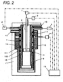
- Fig. 2 shows a hydrogen generator of an embodiment of the present invention.
- the structure of the water evaporation unit 7 of this embodiment differs from that of the illustrative embodiment shown in Fig. 1 .
- the water evaporation unit 7 is configured such that in the vicinity of the conversion catalyst layer 10, the pitch of the metallic round bar 18 serving as a helical partition portion of the water evaporation unit 7 adjacent to an upstream portion the conversion catalyst layer 10 in a flow of the reformed gas, is made smaller than the pitch of the helical round bar 18 located adjacent to a portion of the conversion catalyst layer 10 except the upstream portion thereof.
- the water evaporation unit 7 is configured such that in the vicinity of the selective oxidation catalyst layer 11, the pitch of the metallic round bar 18 serving as the helical partition portion of the water evaporation unit 7 adjacent to an upstream portion of the selective oxidation catalyst layer 11 in a flow of the reformed gas is made smaller than the pitch of the helical round bar 18 located adjacent to a portion of the selective oxidation catalyst layer 11 except the upstream portion thereof.
- the conversion catalyst layer 10 receives the reformed gas from the reforming catalyst layer 9, whereby the amount of CO of 10 to 15% contained in the reformed gas is reduced to 0.5% by shift reaction. Shift reaction is exothermic reaction and mostly takes place in the upstream portion of the conversion catalyst layer 10 supplied with the reformed gas.
- Fig. 3 shows a CO characteristic chart with respect to the temperature of the conversion catalyst. It is seen from Fig. 3 that CO concentration increases at both an excessively high temperature and an excessively low temperature.
- the hot reformed gas is supplied from the reforming catalyst layer 9 to the conversion catalyst layer 10.
- the gas After the gas is subject to exothermic reaction in the upstream portion of the conversion catalyst layer 10, the gas flows toward a downstream portion while accompanied by transfer of heat to the water evaporation unit 7 and dissipation of heat to external surroundings of the conversion catalyst layer. Hence, the temperature decreases from the upstream portion to the downstream portion of the conversion catalyst layer.
- the concentration of CO in the converted gas supplied from the conversion catalyst layer 10 represents a characteristic, such as that shown in Fig. 3 , according to the temperature of the catalyst at the exit of the conversion catalyst layer 10. Accordingly, when the temperature of the exit of the conversion catalyst layer becomes too low, CO in the converted gas comes to 0.5% or more.
- the exit of the conversion catalyst layer 10 is configured so as to assume a temperature at which the concentration of CO does not exceed 0.5%.
- the temperature of the exit of the conversion catalyst layer is set to a certain level so as not to become too low, the temperature of the upstream portion of the conversion catalyst layer 10 also increases correspondingly. If the temperature of the catalyst is excessively high, catalyst (Cu-Zn, Fe-Cr, or the like) on a catalyst carrier that exhibits catalytic reaction becomes larger through aggregation, which deteriorates a catalytic characteristic. Therefore, it is necessary to prevent excessively high temperature of the catalyst so as not to exceed a heat resistance temperature at which the catalytic characteristic becomes worse.
- a temperature increase in the upstream portion of the catalyst layer has to be reduced while the temperature of the downstream portion of the catalyst layer is set to a high level to some extent.
- the pitch of the helical round bar 18 in the upstream portion of the conversion catalyst layer 10 is made smaller than the pitch of the round bar 18 in the portion of the conversion catalyst layer 10 except the upstream portion thereof, thereby making longer a period of time during which water or steam having a low temperature flows through the water evaporation unit 7. The amount of heat exchange between the water evaporation unit 7 and the upstream portion of the conversion catalyst layer 10 is thereby increased.
- the temperature of the conversion catalyst layer 10 can be suppressed so as not to exceed the heat resistance temperature of the catalyst. Also, the temperature of the downstream portion of the conversion catalyst layer 10 can be maintained to a higher level, so that the stable characteristic of the hydrogen generator can be maintained.
- the selective oxidation catalyst layer 11 receives the converted gas from the conversion catalyst layer 10 and air from the selective oxidation air supply unit 14, whereby the amount of CO of 0.5% contained in the converted gas is reduced to 10 ppm or less by means of selective oxidation reaction.
- the selective oxidation reaction is also exothermic reaction and immediately takes place when the converted gas and the air is supplied to the selective oxidation catalyst layer 11.
- Fig. 4 shows a CO characteristic chart with respect to the temperature of the selective oxidation catalyst. According to Fig. 4 , the amount of CO is understood to become high even when the temperature is excessively high or low.
- the temperature of the selective oxidation catalyst layer 11 decreases from the upstream portion to the downstream portion after exothermic reaction occurred in the upstream portion of the selective oxidation catalyst layer 11 by means of transfer of heat to the water evaporation unit 7 and dissipation of heat to external surroundings.
- a state of CO at the exit of the selective oxidation catalyst layer 11 is determined by the temperature of the upstream portion. It is preferable that the upstream portion is set in a temperature state in which a superior CO characteristic shown in Fig. 4 is exhibited. However, if the temperature is excessively decreased, the temperature of the exit of the selective oxidation catalyst layer 11 also decreases, so that the temperature of the produced gas exiting from the selective oxidation catalyst layer 11 also decreases.
- dew condensation of steam in the produced gas may occur. If dew condensation occurs and if dew-condensed water is supplied to the selective oxidation catalyst layer 11, the heat of the catalyst having a high temperature will be absorbed by re-evaporation of dew-condensed water, whereupon the temperature of the catalyst decreases.
- the temperature balance of the selective oxidation catalyst layer 11 is then lowered, thereby causing a temperature in the upstream portion of the selective oxidation catalyst layer to be lowered, which may avoid CO contained in the produced gas from being reduced to a level of 10 ppm or less.
- water the due-condensed water
- the amount of heat exchange between the water evaporation unit 7 and the upstream portion of the selective oxidation catalyst layer 11 has to be increased.
- the pitch of the helical round bar 18 in the upstream portion of the selective oxidation catalyst layer 11 is made smaller than the pitch of the round bar 18 in the portion of the selective oxidation catalyst layer 11 except the upstream portion thereof, thereby making the period of time during which low-temperature water or steam flows through the water evaporation unit 7 longer than the period of time during which the water or steam flows through the remaining portion of the selective oxidation catalyst layer 11, whereby the amount of heat exchange between the water evaporation unit 7 and the selective oxidation catalyst layer 11 is increased.
- An increase in the temperature of the upstream portion of the selective oxidation catalyst layer 11 is thereby prevented, so that a temperature distribution from the upstream portion to the downstream portion can be made smaller.
- stable operation of the hydrogen generator can be realized.
- the pitch between the flow channel member (the round bar 8) of the water evaporation unit 7 is changed according to the amount of heat exchange between the combustion exhaust gas flow channel 16 and the carbon monoxide reduction unit (the conversion catalyst layer 10 and the selective oxidation catalyst layer 11). Moreover, the pitch between the flow channel member (the round bar 8) of the water evaporation unit 7 is made smaller at a location where an increase in the amount of heat exchange is desired. As a result, the temperature of the reforming catalyst layer can be maintained appropriately, and performance of the hydrogen generator can be stabilized.
- the amount of heat exchange referred to herein means the amount of heat exchange per unit area.
- both the pitch of the helical round bar 18 in the upstream portion of the conversion catalyst layer 10 and the pitch of the helical round bar 18 in the upstream portion of the selective oxidation catalyst layer 11 are made smaller.
- the pitches may be configured separately so as to adapt to the hydrogen generator.
- only the pitch of the round bar 18 in the upstream portion of the conversion catalyst layer 10 may also be made smaller in accordance with the present invention, or only the pitch of the round bar 18 in the upstream portion of the selective oxidation catalyst layer 11 may be made smaller, not in accordance with the present invention.
- the flow channel in the water evaporation unit 7 is formed by use of the helical round bars 8 and 18.
- a material having any shape such as a helical plate-like or pipe-like material, may also be used for forming the flow channel, so long as the material enables smooth flow of water by means of a helical shape having a partitioning function.
- the hydrogen generator of the present invention realizes stable supply of hydrogen in the form of equipment that is compact, highly efficient and achieves low cost.
- the hydrogen generator is useful, for example, as equipment for supplying a produced gas containing hydrogen to a home fuel cell system.
Description
- The present invention relates to a hydrogen generator configured to generate a produced gas containing a high concentration of hydrogen by using a hydrocarbon fuel, such as a town gas and an LPG, as a raw gas, and also relates to a fuel cell power generator including a fuel cell configured to generate electric power by using hydrogen produced by the hydrogen generator.
- The fuel cell power generator mainly includes: a hydrogen generator configured to generate a produced gas containing a high concentration of hydrogen; and a fuel cell configured to generate electric power by using hydrogen generated by the hydrogen generator.
- The hydrogen generator includes: a reforming unit configured to generate a reformed gas containing hydrogen, methane, carbon monoxide (in an amount of about 10 to 15 %), carbon dioxide and steam by subjecting a raw gas and steam to steam-reforming reaction using a reforming catalyst in which a hydrocarbon fuel, such as a town gas and an LPG, is used as the raw gas; and a CO elimination unit configured to eliminate carbon monoxide exhibiting poisoning action to a fuel cell from the reformed gas.
- When a proton exchange membrane fuel cell is used as a fuel cell, a concentration of carbon monoxide contained in the reformed gas is required to be eliminated to about 10 ppm. Generally, the CO elimination unit includes two-stage units which includes: a conversion unit configured to eliminate carbon monoxide to about 0.5% by shift reaction using a conversion catalyst; and a selective oxidation unit configured to mix carbon monoxide and oxygen by using a selective oxidation catalyst, thereby oxidizing carbon monoxide through selective oxidation reaction and reducing the concentration of CO to 10 ppm or less.
- From the viewpoint of a reduction of the size, enhancement of efficiency, enhancement of a start-up characteristic, enhancement of driving stability, and a cost reduction attributable to simplification of a structure, various devices is proposed as a hydrogen generator. As an example thereof, in order to realize a compact, highly efficient hydrogen generator, there is provided a hydrogen generator including a reforming unit and a CO elimination unit which are integrated and also a water evaporation unit which is provided integrally adjacent to a catalyst layer rather than being provided outside the hydrogen generator. According to the structure, an optimum heat balance and stable operation are achieved while heat in the hydrogen generator is utilized to the maximum level, thereby reducing the size of the structure of the hydrogen generator and also reducing cost of the hydrogen generator.
- However, when an operating state of the hydrogen generator (for example, power generation load on a fuel cell in a hydrogen generator built in a fuel cell system) changes, an amount of hydrogen to be generated is reduced or increased by changing a raw material supply amount and a water supply amount. When the water supply amount is changed from a small amount to a large amount, a larger amount of water is fed to the water evaporation unit.
- The water evaporation unit is configured to balance so as to evaporate water by heat of a combustion exhaust gas from a burner surrounding the water evaporation unit and heat of a catalyst layer. However, when a large amount of water is suddenly supplied, the supplied water is not fully evaporated according to circumstances, whereby some of unvaporized water may be supplied to a reforming catalyst in the form of a droplet.
- When the droplets are supplied to the reforming catalyst, the droplets absorb latent heat of the reforming catalyst during evaporation of the droplets, so that the temperature of the reforming catalyst locally and suddenly falls. The temperature fall also induces a fall in the temperature of the catalysis located in surrounding areas. As a result, the transforming catalyst as a whole can not maintain a stable temperature state thereof, which may cause fluctuations in the amount of hydrogen generated.
- In the catalyst supplied with the droplets, an instantaneous temperature fall, so that the catalyst may receive thermal shock, and cracking or exfoliation may occur. Accordingly, in a related-art structure, a second evaporation unit is provided in a lower portion of a downstream side of the water evaporation unit, and a partition wall is provided on the lower portion and the side portion of the second evaporation unit. According to the structure, even if droplets are ejected from the evaporation unit, the droplets will be trapped by the lower portion of the second evaporation unit, and only the steam generated by evaporating droplets which have been trapped is sent from the second evaporation unit (see, for example, Patent Document 1).
- Patent Document 1:
JP-A-2008-63171 - However, an increase in the number of components and complication of the structure may lead to an increase in cost of components or manufacturing cost. Further, when an evaporation unit that is sufficiently long enough to complete evaporation of water is formed without use of such a trapping structure, the size of the entirety of the hydrogen generator increases, and the surface area of the generator also becomes large. Thus, an amount of heat discharge becomes greater, which deteriorates the efficiency of the hydrogen generator (i.e., effective utilization of heat). Further, an increase in the size of the generator also leads to a cost increase, so that a value of the hydrogen generator is degraded.
- Further, when a flow channel of a water evaporation unit is formed as a single unit by a configuration in which the evaporation unit and a catalyst layer are provided adjacent to each other (Patent Document 1), the catalyst layer and the evaporation unit uniformly exchange heat in a direction of flow of the catalyst layer. In the catalyst layer such as a conversion catalyst layer and a selective oxidation catalyst layer, conversion reaction or a selective oxidation reaction occurs in an upstream portion of the catalyst layer which is an immediate neighborhood of its entrance. Therefore, the temperature of the upstream portion of the catalyst layer increases due to heat of reaction. In the meantime, the temperature of a middle flow portion of the catalyst layer or a downstream portion thereof near an exit decreases due to exchange of heat between the catalyst layer and the water evaporation unit.
- Therefore, the temperature of the upstream portion of the catalyst layer increases, and the temperature of the downstream portion decreases. The characteristics of the catalyst degrade when a temperature of the catalyst layer is too high and too low. Further, when the temperature of the catalyst layer is too high, the catalyst degrades by high temperature. Consequently, the catalyst has to be used at a heat resistance temperature or below. If a large temperature distribution exists in the catalyst layer, the characteristics of the catalyst may not sufficiently be assured.
- An object of the present invention is to provide a hydrogen generator which can appropriately maintain the temperature of a reforming catalyst layer and of a conversion catalyst, and which exhibits stable performance.
- In order to solve the above-mentioned problems, a hydrogen generator according to the present invention comprises the features of
claim 1. - According to the invention, the temperature of the reforming catalyst layer can be maintained appropriately, and the performance of the hydrogen generator can be stabilized.
-
-
Fig. 1 is a schematic diagram showing a hydrogen generator of an illustrative embodiment, not part of the invention. -
Fig. 2 is a schematic diagram showing a hydrogen generator of an embodiment of the present invention. -
Fig. 3 is a characteristic chart of a conversion catalyst. -
Fig. 4 is a characteristic chart of a selective oxidation catalyst. - A hydrogen generator of the invention includes the features of
claim 1. - In the hydrogen generator of the invention, the helical partition portion can include a metallic round bar.
- According to this invention, the helical partition portion can be made by a simple structure.
- A fuel cell power generator of the invention includes the hydrogen generator in any one of the above inventions.
- According to the tenth invention, the fuel cell power generator can stably be operated by providing the hydrogen generator that implements performance of stable operation.
-
Fig. 1 shows a hydrogen generator of an illustrative embodiment. The hydrogen generator includes aburner 4. Theburner 4 mixes a fuel gas supplied from a fuelgas supply unit 1 with air supplied from anair fan 3 and delivered via anair flow channel 2, thereby building a fire. A combustion exhaust gas generated by theburner 4 flows into a combustion exhaustgas flow channel 16 located inside acylinder 100 and is discharged outside the hydrogen generator via anoutlet 13. - A
water evaporation unit 7 is placed outside the combustion exhaustgas flow channel 16. Thewater evaporation unit 7 receives a raw gas from a raw gas supply unit 5 and water from a water supply unit 6 and mixes the supplied water, as steam, with the raw gas. Thewater evaporation unit 7 is structured such that ametallic round bar 8 serving as a helical partition portion is sandwiched between thecylinder 100 and acylinder 101 so as to form a space between theround bar 8 and that the raw gas and the water are guided through the space along theround bar 8. Accordingly, the space of thewater evaporation unit 7 is partitioned by thehelical round bar 8, to thus form a helical flow channel surrounding an outer periphery of thecylinder 100. In other words, thewater evaporation unit 7 includes themetallic round bar 8 disposed outside the combustion exhaustgas flow channel 16 and serving as a flow channel member through which the raw gas and water flow. - In order to effectively utilize combustion heat of the
burner 4, the generator as a whole is covered with aheat insulating material 17. - A helical pitch of the
round bar 8 in a downstream portion of thewater evaporation unit 7 is made smaller than a helical pitch of theround bar 8 in an intermediate stream portion of thewater evaporation unit 7 and a helical pitch of theround bar 8 in an upstream portion thereof. The gas mixture containing the raw material gas and the steam and sent from thewater evaporation unit 7 is supplied to a reformingcatalyst layer 9 located outside the combustion exhaustgas flow channel 16 and in the lower portion of thewater evaporation unit 7. - A reformed gas sent from the reforming
catalyst layer 9 is supplied to aconversion catalyst layer 10 placed outside thewater evaporation unit 7. Further, a converted gas sent from theconversion catalyst layer 10 is mixed with the air from a selective oxidizedair supply unit 14 and subsequently supplied to a selectiveoxidization catalyst layer 11 situated in an upper portion of theconversion catalyst layer 10 outside thewater evaporation unit 7. The produced gas from the selectiveoxidation catalyst layer 11 is sent from the hydrogen generator via a producedgas exit 12 as a produced gas containing a high concentration of hydrogen with carbon monoxide in an amount of 10 ppm or less. Theconversion catalyst layer 10 receives a reformed gas and reduces carbon monoxide in the reformed gas by shift reaction of the conversion catalyst. The converted gas flows from theconversion catalyst layer 10 and into the selectiveoxidation catalyst layer 11, and an oxidizing agent is supplied to the selectiveoxidation catalyst layer 11, whereby the selectiveoxidation catalyst layer 11 reduces carbon monoxide in the converted gas by means of a selective oxidation catalyst. A combination of theconversion catalyst layer 10 with the selectiveoxidation catalyst layer 11 is referred to as a carbon monoxide reduction unit. However, the carbon monoxide reduction unit may include at least theconversion catalyst layer 10. - The fuel gas, the air supplied to the
burner 4, the raw gas, the water supplied to thewater evaporation unit 7, and the selective oxidized air supplied to the converted gas from theconversion catalyst layer 10 can be controlled by the fuelgas supply unit 1, theair fan 3, the raw gas supply unit 5, the water supply unit 6, and the selective oxidizedair supply unit 14, by means of a signal from acontrol unit 15. - The fuel
gas supply unit 1, theair fan 3, the raw gas supply unit 5, the water supply unit 6, and the selective oxidizedair supply unit 14 are configured so as to be able to regulate flow rates of respective supplies (a fuel gas, a raw gas, water, a combustible gas such as an off-gas, and air). A configuration for regulating a flow rate may be a supply pump (drive means) capable of changing a discharge flow rate of a supply or a fluid control mechanism including a combination of a supply source and a valve for regulating a flow rate of a supply disposed in a downstream-side flow channel. - Operation of the respective units of the hydrogen generator including the foregoing configuration is now described.
- The
burner 4 mixes the fuel gas with air and subjects the gas mixture to a high voltage electric discharge (a configuration for the electric discharge is not shown), thereby building a fire and generating a high-temperature combustion exhaust gas, and supplies the gas to the combustion exhaustgas flow channel 16. - The
water evaporation unit 7 which has received water and a raw material vaporizes water by the heat from the combustion exhaust gas in the combustion exhaustgas flow channel 16 flowing through the inner side of thewater evaporation unit 7 through heat exchange. Concurrently, the steam is mixed with the raw gas flowing through the same flow channel in thewater evaporation unit 7, and a resultant gas is fed as a gas mixture to the reformingcatalyst layer 9. The reformingcatalyst layer 9 is heated (generally to 600 to 700 °C) by the high-temperature combustion exhaust gas flowing on the inner side of the reformingcatalyst layer 9. The gas mixture containing the raw gas and the steam is supplied to the reformingcatalyst layer 9, whereby a reformed gas containing hydrogen, carbon monoxide, and carbon dioxide is produced by steam-reforming reaction. - The
conversion catalyst layer 10 is maintained at a temperature (150 to 300 °C) optimal for shift reaction by the heat exchange with thewater evaporation unit 7 located adjacent to and on an inner side of thecatalyst layer 10. A high concentration of carbon monoxide (10 to 15%) in the reformed gas is converted into carbon dioxide, whereby the concentration of carbon monoxide is reduced to a low level (around 0.5%). The selectiveoxidation catalyst layer 11 is also maintained at a temperature (around 150 °C) optimal for selective oxidizing reaction by the heat exchanged with thewater evaporation unit 7 located adjacent to and on an inner side of the selectiveoxidation catalyst layer 11. The air supplied from the selective oxidationair supply unit 14 is mixed into the converted gas, whereby the carbon monoxide in the converted gas is reduced to an ultra-lox concentration of 10 ppm or less by selective oxidation reaction. - When driving load (i.e., an amount of hydrogen produced) of the hydrogen generator is changed, the
control unit 15 changes supply conditions so as to adapt to the driving load. For example, when there is received a command for changing a condition (TDR 50) for producing an amount of hydrogen that is 50% of a rated condition to a condition (TDR 100) for producing an amount of hydrogen conforming to the rated condition, the raw gas supply unit 5, the water supply unit 6, and the selective oxidationair supply unit 14 are controlled according to a signal from thecontrol unit 15, whereby the amount of raw gas, the amount of water supply, and the amount of selective oxidization air are increased. - At this time,
water evaporation unit 7 increases the amount of water from the condition under which water necessary for theTDR 50 has been supplied to an amount of water required for the TDR 100 (e.g., 10 g/min). In general, the amount of water required forTDR 100 is approximately twice the amount of water required for TDR 50 (e.g., 5 g/min). Therefore, an evaporation completion point in thewater evaporation unit 7 shifts downstream. - Specifically, under
TDR 50, water at a room temperature (about 20 °C) supplied from the water supply unit 6 enters thewater evaporation unit 7 and is warmed by receiving heat of an exhaust gas flowing through the combustion exhaustgas flow channel 16, heat of the selectiveoxidation catalyst layer 11, and heat of theconversion catalyst layer 10. As a result, the evaporation of the water completely finishes in a vicinity of a midstream portion of theconversion catalyst layer 10, whereby the water turns into steam having a temperature of 100 °C or more. - However, when the amount of water is supplied under
TDR 100 which is twice the amount of water, the evaporation of the water does not finish in the vicinity of the midstream portion of theconversion catalyst layer 10, and the water is in a steam-liquid two-layer state having a temperature of 100 °C in the midstream portion. The water flows further downstream, to thus receive heat of theconversion catalyst layer 10 and heat of the combustion exhaust gas, whereby evaporation of water is completed at the exit of theconversion catalyst layer 10 and at a further downstream portion. - Since the reforming
catalyst layer 9 exists downstream of thewater evaporation unit 7 at this time, the evaporation completion point deviates downstream, and the evaporation of the water finishes in the reformingcatalyst layer 9 after exiting thewater evaporation unit 7. At this time, liquid water having a temperature of 100 °C is supplied to the reformingcatalyst layer 9. Since evaporation requires latent heat, a great amount of heat of a surrounding catalyst will be absorbed, and the catalyst may come to a temperature of 100 °C. - In particular, when the evaporation completion point is situated in the midstream portion of the
conversion catalyst layer 10 underTDR 50, the temperature of the steam increases because of sensible heat at a downstream portion with respect to the evaporation completion point. Therefore, an upstream portion of the reformingcatalyst layer 9 is at a high temperature of 400 °C. - If the amount of water has increased from this state as in
TDR 100 such that the state is suddenly changed to a state in which the evaporation completion point is located in the reformingcatalyst layer 9, the temperature of the upstream portion of the reformingcatalyst layer 9 sharply falls from 400 °C to 100 °C. When thermal shock due to a temperature fall is applied to the catalyst, cracking of the catalyst may occur. - Further, a temperature fall may occur in the entire catalyst layer thereby causing a temperature of the entire catalyst layer to fall, or a temperature distribution including a locally low temperature may occur due to a local temperature fall. If such a temperature state occurs, reforming reaction of the reforming
catalyst layer 9 will not be stably, sufficiently performed. As a result, the amount of hydrogen produced will become smaller, or the amount of hydrogen produced will become unstable. - In the present illustrative embodiment, in order to promote heat transfer in the downstream portion of the
water evaporation unit 7 so as to prevent occurrence of such a failure, the pitch of the helicalround bar 8 in the downstream portion of thewater evaporation unit 7 is made smaller than the pitch in a portion except the downstream portion of thewater evaporation unit 7. A reduction in pitch can prolong a time during which the water flowing along the helicalround bar 8 reaches the reformingcatalyst layer 9, which can prolong a time for the water to receive heat from the combustion exhaust gas, theconversion catalyst layer 10, and surrounding high-temperature areas. Consequently, water is completely evaporated before reaching the reformingcatalyst layer 9. - Accordingly, the pitch of the helical
round bar 8 formed in the downstream portion of thewater evaporation unit 7 is made smaller than the pitch in the portion except the downstream portion of thewater evaporation unit 7, whereby the helical flow channel in the downstream portion of thewater evaporation unit 7 becomes longer. A traveling time of the water flowing through the helical flow channel also becomes longer, and the amount of heat exchange between the downstream portion of thewater evaporation unit 7 and the combustion exhaustgas flow channel 16 corresponding to the downstream portion becomes greater. By the increase of the amount of heat exchange, water is completely evaporated, and supply of droplets to the reformingcatalyst layer 9 is prevented, so that performance of the hydrogen generator can be stabilized. - In the embodiment, the pitch between the flow channel member (the round bar 8) of the
water evaporation unit 7 is changed according to the amount of heat exchange between the combustionexhaust gas channel 16 and thewater evaporation unit 7. In addition, the pitch of the flow channel member (the round bar 8) of thewater evaporation unit 7 in the portion where an increase in the amount of heat exchange is desired is made small. Consequently, the temperature of the reforming catalyst layer can be maintained appropriately, and the performance of the hydrogen generator can be stabilized. - The amount of heat exchange referred to in the present embodiment means an amount of heat exchange per unit area.
-
Fig. 2 shows a hydrogen generator of an embodiment of the present invention. The structure of thewater evaporation unit 7 of this embodiment differs from that of the illustrative embodiment shown inFig. 1 . - In
Fig. 2 , thewater evaporation unit 7 is configured such that in the vicinity of theconversion catalyst layer 10, the pitch of themetallic round bar 18 serving as a helical partition portion of thewater evaporation unit 7 adjacent to an upstream portion theconversion catalyst layer 10 in a flow of the reformed gas, is made smaller than the pitch of thehelical round bar 18 located adjacent to a portion of theconversion catalyst layer 10 except the upstream portion thereof. - Further, the
water evaporation unit 7 is configured such that in the vicinity of the selectiveoxidation catalyst layer 11, the pitch of themetallic round bar 18 serving as the helical partition portion of thewater evaporation unit 7 adjacent to an upstream portion of the selectiveoxidation catalyst layer 11 in a flow of the reformed gas is made smaller than the pitch of thehelical round bar 18 located adjacent to a portion of the selectiveoxidation catalyst layer 11 except the upstream portion thereof. - The
conversion catalyst layer 10 receives the reformed gas from the reformingcatalyst layer 9, whereby the amount of CO of 10 to 15% contained in the reformed gas is reduced to 0.5% by shift reaction. Shift reaction is exothermic reaction and mostly takes place in the upstream portion of theconversion catalyst layer 10 supplied with the reformed gas. -
Fig. 3 shows a CO characteristic chart with respect to the temperature of the conversion catalyst. It is seen fromFig. 3 that CO concentration increases at both an excessively high temperature and an excessively low temperature. - The hot reformed gas is supplied from the reforming
catalyst layer 9 to theconversion catalyst layer 10. After the gas is subject to exothermic reaction in the upstream portion of theconversion catalyst layer 10, the gas flows toward a downstream portion while accompanied by transfer of heat to thewater evaporation unit 7 and dissipation of heat to external surroundings of the conversion catalyst layer. Hence, the temperature decreases from the upstream portion to the downstream portion of the conversion catalyst layer. The concentration of CO in the converted gas supplied from theconversion catalyst layer 10 represents a characteristic, such as that shown inFig. 3 , according to the temperature of the catalyst at the exit of theconversion catalyst layer 10. Accordingly, when the temperature of the exit of the conversion catalyst layer becomes too low, CO in the converted gas comes to 0.5% or more. - Accordingly, the exit of the
conversion catalyst layer 10 is configured so as to assume a temperature at which the concentration of CO does not exceed 0.5%. However, the temperature of the exit of the conversion catalyst layer is set to a certain level so as not to become too low, the temperature of the upstream portion of theconversion catalyst layer 10 also increases correspondingly. If the temperature of the catalyst is excessively high, catalyst (Cu-Zn, Fe-Cr, or the like) on a catalyst carrier that exhibits catalytic reaction becomes larger through aggregation, which deteriorates a catalytic characteristic. Therefore, it is necessary to prevent excessively high temperature of the catalyst so as not to exceed a heat resistance temperature at which the catalytic characteristic becomes worse. - To this end, a temperature increase in the upstream portion of the catalyst layer has to be reduced while the temperature of the downstream portion of the catalyst layer is set to a high level to some extent. As described in the embodiment shown in
Fig. 2 , the pitch of thehelical round bar 18 in the upstream portion of theconversion catalyst layer 10 is made smaller than the pitch of theround bar 18 in the portion of theconversion catalyst layer 10 except the upstream portion thereof, thereby making longer a period of time during which water or steam having a low temperature flows through thewater evaporation unit 7. The amount of heat exchange between thewater evaporation unit 7 and the upstream portion of theconversion catalyst layer 10 is thereby increased. - In that case, the temperature of the
conversion catalyst layer 10 can be suppressed so as not to exceed the heat resistance temperature of the catalyst. Also, the temperature of the downstream portion of theconversion catalyst layer 10 can be maintained to a higher level, so that the stable characteristic of the hydrogen generator can be maintained. - The selective
oxidation catalyst layer 11 receives the converted gas from theconversion catalyst layer 10 and air from the selective oxidationair supply unit 14, whereby the amount of CO of 0.5% contained in the converted gas is reduced to 10 ppm or less by means of selective oxidation reaction. The selective oxidation reaction is also exothermic reaction and immediately takes place when the converted gas and the air is supplied to the selectiveoxidation catalyst layer 11. -
Fig. 4 shows a CO characteristic chart with respect to the temperature of the selective oxidation catalyst. According toFig. 4 , the amount of CO is understood to become high even when the temperature is excessively high or low. Like theconversion catalyst layer 10, the temperature of the selectiveoxidation catalyst layer 11 decreases from the upstream portion to the downstream portion after exothermic reaction occurred in the upstream portion of the selectiveoxidation catalyst layer 11 by means of transfer of heat to thewater evaporation unit 7 and dissipation of heat to external surroundings. - Selective oxidation reaction ends at the upstream portion after having entered the selective
oxidation catalyst layer 11. Therefore, a state of CO at the exit of the selectiveoxidation catalyst layer 11 is determined by the temperature of the upstream portion. It is preferable that the upstream portion is set in a temperature state in which a superior CO characteristic shown inFig. 4 is exhibited. However, if the temperature is excessively decreased, the temperature of the exit of the selectiveoxidation catalyst layer 11 also decreases, so that the temperature of the produced gas exiting from the selectiveoxidation catalyst layer 11 also decreases. - When the temperature of the produced gas comes to a level equal to a dew point or less due to excessive decrease of the temperature of the produced gas, dew condensation of steam in the produced gas may occur. If dew condensation occurs and if dew-condensed water is supplied to the selective
oxidation catalyst layer 11, the heat of the catalyst having a high temperature will be absorbed by re-evaporation of dew-condensed water, whereupon the temperature of the catalyst decreases. - The temperature balance of the selective
oxidation catalyst layer 11 is then lowered, thereby causing a temperature in the upstream portion of the selective oxidation catalyst layer to be lowered, which may avoid CO contained in the produced gas from being reduced to a level of 10 ppm or less. Moreover, water (the due-condensed water) evaporates at a location differing from a usual location. For this reason, a great volumetric change occurs due to transformation from water to steam at the evaporation, and a stable characteristic of the entire hydrogen generator can not be maintained for reasons of turbulence (pulsation) in a gas flowing in the interior of the hydrogen generator. - Accordingly, in order to prevent an increase in the temperature of the upstream portion of the catalyst layer while a temperature fall in the downstream portion of the selective
oxidation catalyst layer 11 is suppressed, the amount of heat exchange between thewater evaporation unit 7 and the upstream portion of the selectiveoxidation catalyst layer 11 has to be increased. As described in the embodiment, the pitch of thehelical round bar 18 in the upstream portion of the selectiveoxidation catalyst layer 11 is made smaller than the pitch of theround bar 18 in the portion of the selectiveoxidation catalyst layer 11 except the upstream portion thereof, thereby making the period of time during which low-temperature water or steam flows through thewater evaporation unit 7 longer than the period of time during which the water or steam flows through the remaining portion of the selectiveoxidation catalyst layer 11, whereby the amount of heat exchange between thewater evaporation unit 7 and the selectiveoxidation catalyst layer 11 is increased. An increase in the temperature of the upstream portion of the selectiveoxidation catalyst layer 11 is thereby prevented, so that a temperature distribution from the upstream portion to the downstream portion can be made smaller. Thus, stable operation of the hydrogen generator can be realized. - In the present embodiment, the pitch between the flow channel member (the round bar 8) of the
water evaporation unit 7 is changed according to the amount of heat exchange between the combustion exhaustgas flow channel 16 and the carbon monoxide reduction unit (theconversion catalyst layer 10 and the selective oxidation catalyst layer 11). Moreover, the pitch between the flow channel member (the round bar 8) of thewater evaporation unit 7 is made smaller at a location where an increase in the amount of heat exchange is desired. As a result, the temperature of the reforming catalyst layer can be maintained appropriately, and performance of the hydrogen generator can be stabilized. - The amount of heat exchange referred to herein means the amount of heat exchange per unit area.
- In the embodiment, both the pitch of the
helical round bar 18 in the upstream portion of theconversion catalyst layer 10 and the pitch of thehelical round bar 18 in the upstream portion of the selectiveoxidation catalyst layer 11 are made smaller. However, the pitches may be configured separately so as to adapt to the hydrogen generator. For example, only the pitch of theround bar 18 in the upstream portion of theconversion catalyst layer 10 may also be made smaller in accordance with the present invention, or only the pitch of theround bar 18 in the upstream portion of the selectiveoxidation catalyst layer 11 may be made smaller, not in accordance with the present invention. - The structure in which the illustrative embodiment and this embodiment are simultaneously performed in combination may be adopted.
- In the embodiments, the flow channel in the
water evaporation unit 7 is formed by use of thehelical round bars - Moreover, stable operation of the fuel cell power generator becomes possible, by providing the fuel cell power generator with the hydrogen generator described in the first embodiment or the second embodiment.
- The present invention is not limited to the descriptions provided for the embodiments and is scheduled to be subjected to modifications and alterations conceived by the persons having ordinal skill in the art based on the descriptions of the specification and the well-known techniques. The modifications and alterations shall fall within a range in which protection is sought.
- The hydrogen generator of the present invention realizes stable supply of hydrogen in the form of equipment that is compact, highly efficient and achieves low cost. The hydrogen generator is useful, for example, as equipment for supplying a produced gas containing hydrogen to a home fuel cell system.
-
- 1 FUEL GAS SUPPLY UNIT
- 2 AIR FLOW CHANNEL
- 3 AIR FAN
- 4 BURNER
- 5 RAW GAS SUPPLY UNIT
- 6 WATER SUPPLY UNIT
- 7 WATER EVAPORATION UNIT
- 8, 18 ROUND BAR
- 9 REFORMING CATALYST LAYER
- 10 CONVERSION CATALYST LAYER
- 11 SELECTIVE OXIDATION CATALYST LAYER
- 12 PRODUCED GAS EXIT
- 13 OUTLET
- 14 SELECTIVE OXIDATION AIR SUPPLY UNIT
- 15 CONTROL UNIT
- 16 COMBUSTION EXHAUST GAS FLOW CHANNEL
- 17 INSULATING MATERIAL
- 100 CYLINDER
- 101 CYLINDER
Claims (3)
- A hydrogen generator comprising:a raw material supply unit (5) configured to supply a raw gas;a water supply unit (6) configured to supply water;a water evaporation unit (7) connected to the raw material supply unit (5) and the water supply unit (6) and configured to transform supplied water into steam and to mix the steam with the raw gas;a burner (4) connected to a fuel supply unit (1) configured to supply a fuel gas and an air supply unit (3) configured to supply combustion air;a combustion exhaust gas flow channel (16) which is provided on an inner side than the water evaporation unit (7) and through which a combustion exhaust gas from the burner (4) flows;a reforming catalyst layer (9) configured to receive a gas mixture supplied from the water evaporation unit (7) and produce a reformed gas containing hydrogen by steam-reforming reaction of the gas mixture with a reforming catalyst; anda carbon monoxide reduction unit (10, 11) disposed on an outer side than the water evaporation unit (7) and configured to receive the reformed gas and reduce an amount of carbon monoxide contained in the reformed gas,wherein the water evaporation unit (7) comprises a flow channel member (18) provided on an outer side than the combustion exhaust gas flow channel (16) and defining a flow channel through which the raw gas and the water flow,characterized in thatthe flow channel member (18) of the water evaporation unit (7) comprises double cylinders and a helical partition portion sandwiched between the cylinders, andwherein the carbon monoxide reduction unit comprises a conversion catalyst layer (10) configured to receive the reformed gas and to reduce carbon monoxide in the reformed gas by shift reaction using a conversion catalyst,wherein the conversion catalyst layer (10) is disposed adjacent to an outside of the water evaporation unit (7),wherein the water evaporation unit (7) is configured such that a pitch of the helical partition portion (18) is smaller in the water evaporation unit adjacent to the upstream portion of the conversion catalyst layer (10) and is greater in the water evaporation unit adjacent to the remaining portion of the conversion catalyst layer (10), so that the amount of heat exchange between the conversion catalyst layer (10) and the water evaporation unit (7) is higher in the upstream portion of the conversion catalyst layer (10) than in the remaining portion of the conversion catalyst layer (10).
- The hydrogen generator according to claim 1, wherein the helical partition portion comprises a metallic round bar.
- A fuel cell power generator comprising the hydrogen generator according to claim 1 or 2.
Applications Claiming Priority (2)
| Application Number | Priority Date | Filing Date | Title |
|---|---|---|---|
| JP2008128024 | 2008-05-15 | ||
| EP09746366.5A EP2287112B1 (en) | 2008-05-15 | 2009-05-13 | Hydrogen generator and fuel cell power generator |
Related Parent Applications (3)
| Application Number | Title | Priority Date | Filing Date |
|---|---|---|---|
| EP09746366.5 Division | 2009-05-13 | ||
| EP09746366.5A Division-Into EP2287112B1 (en) | 2008-05-15 | 2009-05-13 | Hydrogen generator and fuel cell power generator |
| EP09746366.5A Division EP2287112B1 (en) | 2008-05-15 | 2009-05-13 | Hydrogen generator and fuel cell power generator |
Publications (2)
| Publication Number | Publication Date |
|---|---|
| EP2615058A1 EP2615058A1 (en) | 2013-07-17 |
| EP2615058B1 true EP2615058B1 (en) | 2015-11-04 |
Family
ID=41318534
Family Applications (2)
| Application Number | Title | Priority Date | Filing Date |
|---|---|---|---|
| EP13001895.5A Active EP2615058B1 (en) | 2008-05-15 | 2009-05-13 | Hydrogen generator and fuel cell power generator |
| EP09746366.5A Active EP2287112B1 (en) | 2008-05-15 | 2009-05-13 | Hydrogen generator and fuel cell power generator |
Family Applications After (1)
| Application Number | Title | Priority Date | Filing Date |
|---|---|---|---|
| EP09746366.5A Active EP2287112B1 (en) | 2008-05-15 | 2009-05-13 | Hydrogen generator and fuel cell power generator |
Country Status (8)
| Country | Link |
|---|---|
| US (1) | US8815455B2 (en) |
| EP (2) | EP2615058B1 (en) |
| JP (1) | JP5477748B2 (en) |
| KR (1) | KR101203454B1 (en) |
| CN (1) | CN102099285B (en) |
| CA (1) | CA2724183A1 (en) |
| RU (1) | RU2458854C2 (en) |
| WO (1) | WO2009139159A1 (en) |
Families Citing this family (5)
| Publication number | Priority date | Publication date | Assignee | Title |
|---|---|---|---|---|
| RU2012142177A (en) * | 2010-03-04 | 2014-04-10 | Панасоник Корпорэйшн | DEVICE FOR HYDROGEN PRODUCTION AND ENERGY PRODUCTION SYSTEM BASED ON FUEL ELEMENT |
| JP5610812B2 (en) | 2010-03-30 | 2014-10-22 | Jx日鉱日石エネルギー株式会社 | Hydrogen production apparatus and fuel cell system |
| KR20120047545A (en) * | 2010-11-04 | 2012-05-14 | 삼성에스디아이 주식회사 | Reformer |
| CA2856558C (en) * | 2011-12-06 | 2019-06-11 | Hy9 Corporation | Catalyst-containing reactor system and associated methods |
| CN111732078A (en) * | 2020-06-28 | 2020-10-02 | 鄂尔多斯市国科能源有限公司 | Hydrogen purification device and method |
Family Cites Families (15)
| Publication number | Priority date | Publication date | Assignee | Title |
|---|---|---|---|---|
| SU904764A1 (en) * | 1980-03-26 | 1982-02-15 | Киевский Ордена Трудового Красного Знамени Институт Инженеров Гражданской Авиации | Hydrogen generator |
| JP3405839B2 (en) * | 1994-12-09 | 2003-05-12 | 三洋電機株式会社 | Converter |
| JP3369846B2 (en) * | 1996-05-21 | 2003-01-20 | 三洋電機株式会社 | Reactor for fuel cell |
| AU2002214858A1 (en) * | 2000-10-27 | 2002-05-06 | Questair Technologies, Inc. | Systems and processes for providing hydrogen to fuel cells |
| JP2003187849A (en) * | 2001-12-13 | 2003-07-04 | Fuji Electric Co Ltd | Solid polymer fuel cell power generator |
| CN100345331C (en) | 2002-10-10 | 2007-10-24 | 松下电器产业株式会社 | Hydrogen geneerator and fuel cell system with hydrogen generator |
| JP2004149402A (en) * | 2002-10-10 | 2004-05-27 | Matsushita Electric Ind Co Ltd | Hydrogen generator and fuel cell system having the same |
| RU2243147C1 (en) * | 2003-05-29 | 2004-12-27 | Открытое Акционерное общество "Ракетно-космическая корпорация "Энергия" имени С.П.Королева" | Hydrogen generator for transport power plant |
| JP4418358B2 (en) * | 2004-12-14 | 2010-02-17 | 本田技研工業株式会社 | Heat exchanger |
| JP4870491B2 (en) * | 2005-07-27 | 2012-02-08 | 富士電機株式会社 | Fuel reformer |
| JP2007145218A (en) | 2005-11-29 | 2007-06-14 | Honda Motor Co Ltd | Air bag device of vehicle |
| WO2007145218A1 (en) * | 2006-06-12 | 2007-12-21 | Panasonic Corporation | Hydrogen generation device and fuel cell system equipped with it |
| JP4870499B2 (en) | 2006-09-06 | 2012-02-08 | パナソニック電工株式会社 | Hydrogen production apparatus and fuel cell power generation apparatus |
| JP2008128024A (en) | 2006-11-17 | 2008-06-05 | Hitachi Ltd | Variable displacement vane pump |
| US8178062B2 (en) * | 2007-09-27 | 2012-05-15 | Sanyo Electric Co., Ltd. | Reforming apparatus for fuel cell |
-
2009
- 2009-05-13 EP EP13001895.5A patent/EP2615058B1/en active Active
- 2009-05-13 JP JP2010511884A patent/JP5477748B2/en active Active
- 2009-05-13 CA CA2724183A patent/CA2724183A1/en not_active Abandoned
- 2009-05-13 RU RU2010146222/05A patent/RU2458854C2/en active
- 2009-05-13 CN CN2009801174012A patent/CN102099285B/en active Active
- 2009-05-13 US US12/992,338 patent/US8815455B2/en not_active Expired - Fee Related
- 2009-05-13 WO PCT/JP2009/002095 patent/WO2009139159A1/en active Application Filing
- 2009-05-13 KR KR1020107025636A patent/KR101203454B1/en not_active IP Right Cessation
- 2009-05-13 EP EP09746366.5A patent/EP2287112B1/en active Active
Also Published As
| Publication number | Publication date |
|---|---|
| JP5477748B2 (en) | 2014-04-23 |
| RU2458854C2 (en) | 2012-08-20 |
| EP2615058A1 (en) | 2013-07-17 |
| EP2287112B1 (en) | 2015-04-29 |
| US8815455B2 (en) | 2014-08-26 |
| KR101203454B1 (en) | 2012-11-21 |
| CN102099285B (en) | 2013-07-03 |
| KR20110008230A (en) | 2011-01-26 |
| US20110065011A1 (en) | 2011-03-17 |
| CA2724183A1 (en) | 2009-11-19 |
| JPWO2009139159A1 (en) | 2011-09-15 |
| WO2009139159A1 (en) | 2009-11-19 |
| CN102099285A (en) | 2011-06-15 |
| EP2287112A4 (en) | 2012-06-06 |
| RU2010146222A (en) | 2012-06-20 |
| EP2287112A1 (en) | 2011-02-23 |
Similar Documents
| Publication | Publication Date | Title |
|---|---|---|
| JP4830197B2 (en) | Fuel reformer | |
| EP0985635B1 (en) | Hydrogen generating apparatus | |
| EP0798798B1 (en) | Method of and apparatus for reforming fuel and fuel cell system with fuel-reforming apparatus incorporated therein | |
| JP5123442B2 (en) | Hydrogen generator and fuel cell power generation system | |
| EP2615058B1 (en) | Hydrogen generator and fuel cell power generator | |
| JP3667231B2 (en) | Fuel cell device | |
| WO2010010718A1 (en) | Hydrogen generation device and fuel cell system provided therewith | |
| JP2007323972A (en) | Fuel treating device and fuel cell system | |
| JP4902165B2 (en) | Fuel cell reformer and fuel cell system comprising the fuel cell reformer | |
| JP2005294207A (en) | Fuel cell system | |
| JP3515438B2 (en) | CO removal device and fuel cell power generation system | |
| JP2001151502A (en) | Fuel reforming device | |
| JP2010524812A (en) | Two-stage reformer and method of operating the reformer | |
| JP2002211906A (en) | Hydrogen producing system | |
| JP3545254B2 (en) | Fuel cell carbon monoxide remover | |
| US7135049B2 (en) | Method for operating a gas generation device in a fuel cell system | |
| JP3729137B2 (en) | Carbon monoxide removal equipment | |
| JP2001080905A (en) | Operation of fuel reformer | |
| JP2002154806A (en) | Fuel reforming apparatus | |
| JP2006504615A (en) | Distribution of air to remove carbon monoxide in reformate | |
| JP2007087781A (en) | Method of purging anode of fuel cell power generation system | |
| JP2003081610A (en) | Reforming apparatus |
Legal Events
| Date | Code | Title | Description |
|---|---|---|---|
| PUAI | Public reference made under article 153(3) epc to a published international application that has entered the european phase |
Free format text: ORIGINAL CODE: 0009012 |
|
| 17P | Request for examination filed |
Effective date: 20130411 |
|
| AC | Divisional application: reference to earlier application |
Ref document number: 2287112 Country of ref document: EP Kind code of ref document: P |
|
| AK | Designated contracting states |
Kind code of ref document: A1 Designated state(s): AT BE BG CH CY CZ DE DK EE ES FI FR GB GR HR HU IE IS IT LI LT LU LV MC MK MT NL NO PL PT RO SE SI SK TR |
|
| 17Q | First examination report despatched |
Effective date: 20140924 |
|
| RAP1 | Party data changed (applicant data changed or rights of an application transferred) |
Owner name: PANASONIC INTELLECTUAL PROPERTY MANAGEMENT CO., LT |
|
| GRAP | Despatch of communication of intention to grant a patent |
Free format text: ORIGINAL CODE: EPIDOSNIGR1 |
|
| INTG | Intention to grant announced |
Effective date: 20150528 |
|
| GRAS | Grant fee paid |
Free format text: ORIGINAL CODE: EPIDOSNIGR3 |
|
| GRAA | (expected) grant |
Free format text: ORIGINAL CODE: 0009210 |
|
| AC | Divisional application: reference to earlier application |
Ref document number: 2287112 Country of ref document: EP Kind code of ref document: P |
|
| AK | Designated contracting states |
Kind code of ref document: B1 Designated state(s): AT BE BG CH CY CZ DE DK EE ES FI FR GB GR HR HU IE IS IT LI LT LU LV MC MK MT NL NO PL PT RO SE SI SK TR |
|
| REG | Reference to a national code |
Ref country code: GB Ref legal event code: FG4D |
|
| REG | Reference to a national code |
Ref country code: CH Ref legal event code: EP |
|
| REG | Reference to a national code |
Ref country code: AT Ref legal event code: REF Ref document number: 759041 Country of ref document: AT Kind code of ref document: T Effective date: 20151115 |
|
| REG | Reference to a national code |
Ref country code: IE Ref legal event code: FG4D |
|
| REG | Reference to a national code |
Ref country code: DE Ref legal event code: R096 Ref document number: 602009034720 Country of ref document: DE |
|
| REG | Reference to a national code |
Ref country code: NL Ref legal event code: MP Effective date: 20151104 |
|
| REG | Reference to a national code |
Ref country code: LT Ref legal event code: MG4D |
|
| REG | Reference to a national code |
Ref country code: AT Ref legal event code: MK05 Ref document number: 759041 Country of ref document: AT Kind code of ref document: T Effective date: 20151104 |
|
| PG25 | Lapsed in a contracting state [announced via postgrant information from national office to epo] |
Ref country code: NO Free format text: LAPSE BECAUSE OF FAILURE TO SUBMIT A TRANSLATION OF THE DESCRIPTION OR TO PAY THE FEE WITHIN THE PRESCRIBED TIME-LIMIT Effective date: 20160204 Ref country code: NL Free format text: LAPSE BECAUSE OF FAILURE TO SUBMIT A TRANSLATION OF THE DESCRIPTION OR TO PAY THE FEE WITHIN THE PRESCRIBED TIME-LIMIT Effective date: 20151104 Ref country code: IS Free format text: LAPSE BECAUSE OF FAILURE TO SUBMIT A TRANSLATION OF THE DESCRIPTION OR TO PAY THE FEE WITHIN THE PRESCRIBED TIME-LIMIT Effective date: 20160304 Ref country code: ES Free format text: LAPSE BECAUSE OF FAILURE TO SUBMIT A TRANSLATION OF THE DESCRIPTION OR TO PAY THE FEE WITHIN THE PRESCRIBED TIME-LIMIT Effective date: 20151104 Ref country code: LT Free format text: LAPSE BECAUSE OF FAILURE TO SUBMIT A TRANSLATION OF THE DESCRIPTION OR TO PAY THE FEE WITHIN THE PRESCRIBED TIME-LIMIT Effective date: 20151104 Ref country code: HR Free format text: LAPSE BECAUSE OF FAILURE TO SUBMIT A TRANSLATION OF THE DESCRIPTION OR TO PAY THE FEE WITHIN THE PRESCRIBED TIME-LIMIT Effective date: 20151104 Ref country code: IT Free format text: LAPSE BECAUSE OF FAILURE TO SUBMIT A TRANSLATION OF THE DESCRIPTION OR TO PAY THE FEE WITHIN THE PRESCRIBED TIME-LIMIT Effective date: 20151104 |
|
| PG25 | Lapsed in a contracting state [announced via postgrant information from national office to epo] |
Ref country code: AT Free format text: LAPSE BECAUSE OF FAILURE TO SUBMIT A TRANSLATION OF THE DESCRIPTION OR TO PAY THE FEE WITHIN THE PRESCRIBED TIME-LIMIT Effective date: 20151104 Ref country code: LV Free format text: LAPSE BECAUSE OF FAILURE TO SUBMIT A TRANSLATION OF THE DESCRIPTION OR TO PAY THE FEE WITHIN THE PRESCRIBED TIME-LIMIT Effective date: 20151104 Ref country code: GR Free format text: LAPSE BECAUSE OF FAILURE TO SUBMIT A TRANSLATION OF THE DESCRIPTION OR TO PAY THE FEE WITHIN THE PRESCRIBED TIME-LIMIT Effective date: 20160205 Ref country code: FI Free format text: LAPSE BECAUSE OF FAILURE TO SUBMIT A TRANSLATION OF THE DESCRIPTION OR TO PAY THE FEE WITHIN THE PRESCRIBED TIME-LIMIT Effective date: 20151104 Ref country code: PL Free format text: LAPSE BECAUSE OF FAILURE TO SUBMIT A TRANSLATION OF THE DESCRIPTION OR TO PAY THE FEE WITHIN THE PRESCRIBED TIME-LIMIT Effective date: 20151104 Ref country code: PT Free format text: LAPSE BECAUSE OF FAILURE TO SUBMIT A TRANSLATION OF THE DESCRIPTION OR TO PAY THE FEE WITHIN THE PRESCRIBED TIME-LIMIT Effective date: 20160304 Ref country code: SE Free format text: LAPSE BECAUSE OF FAILURE TO SUBMIT A TRANSLATION OF THE DESCRIPTION OR TO PAY THE FEE WITHIN THE PRESCRIBED TIME-LIMIT Effective date: 20151104 |
|
| PG25 | Lapsed in a contracting state [announced via postgrant information from national office to epo] |
Ref country code: CZ Free format text: LAPSE BECAUSE OF FAILURE TO SUBMIT A TRANSLATION OF THE DESCRIPTION OR TO PAY THE FEE WITHIN THE PRESCRIBED TIME-LIMIT Effective date: 20151104 |
|
| REG | Reference to a national code |
Ref country code: DE Ref legal event code: R097 Ref document number: 602009034720 Country of ref document: DE |
|
| PG25 | Lapsed in a contracting state [announced via postgrant information from national office to epo] |
Ref country code: DK Free format text: LAPSE BECAUSE OF FAILURE TO SUBMIT A TRANSLATION OF THE DESCRIPTION OR TO PAY THE FEE WITHIN THE PRESCRIBED TIME-LIMIT Effective date: 20151104 Ref country code: BE Free format text: LAPSE BECAUSE OF NON-PAYMENT OF DUE FEES Effective date: 20160531 Ref country code: RO Free format text: LAPSE BECAUSE OF FAILURE TO SUBMIT A TRANSLATION OF THE DESCRIPTION OR TO PAY THE FEE WITHIN THE PRESCRIBED TIME-LIMIT Effective date: 20151104 Ref country code: SK Free format text: LAPSE BECAUSE OF FAILURE TO SUBMIT A TRANSLATION OF THE DESCRIPTION OR TO PAY THE FEE WITHIN THE PRESCRIBED TIME-LIMIT Effective date: 20151104 Ref country code: EE Free format text: LAPSE BECAUSE OF FAILURE TO SUBMIT A TRANSLATION OF THE DESCRIPTION OR TO PAY THE FEE WITHIN THE PRESCRIBED TIME-LIMIT Effective date: 20151104 |
|
| PLBE | No opposition filed within time limit |
Free format text: ORIGINAL CODE: 0009261 |
|
| STAA | Information on the status of an ep patent application or granted ep patent |
Free format text: STATUS: NO OPPOSITION FILED WITHIN TIME LIMIT |
|
| 26N | No opposition filed |
Effective date: 20160805 |
|
| PG25 | Lapsed in a contracting state [announced via postgrant information from national office to epo] |
Ref country code: SI Free format text: LAPSE BECAUSE OF FAILURE TO SUBMIT A TRANSLATION OF THE DESCRIPTION OR TO PAY THE FEE WITHIN THE PRESCRIBED TIME-LIMIT Effective date: 20151104 |
|
| PG25 | Lapsed in a contracting state [announced via postgrant information from national office to epo] |
Ref country code: LU Free format text: LAPSE BECAUSE OF FAILURE TO SUBMIT A TRANSLATION OF THE DESCRIPTION OR TO PAY THE FEE WITHIN THE PRESCRIBED TIME-LIMIT Effective date: 20160513 Ref country code: BE Free format text: LAPSE BECAUSE OF FAILURE TO SUBMIT A TRANSLATION OF THE DESCRIPTION OR TO PAY THE FEE WITHIN THE PRESCRIBED TIME-LIMIT Effective date: 20151104 |
|
| REG | Reference to a national code |
Ref country code: CH Ref legal event code: PL |
|
| GBPC | Gb: european patent ceased through non-payment of renewal fee |
Effective date: 20160513 |
|
| PG25 | Lapsed in a contracting state [announced via postgrant information from national office to epo] |
Ref country code: CH Free format text: LAPSE BECAUSE OF NON-PAYMENT OF DUE FEES Effective date: 20160531 Ref country code: LI Free format text: LAPSE BECAUSE OF NON-PAYMENT OF DUE FEES Effective date: 20160531 |
|
| REG | Reference to a national code |
Ref country code: IE Ref legal event code: MM4A |
|
| REG | Reference to a national code |
Ref country code: FR Ref legal event code: ST Effective date: 20170131 |
|
| PG25 | Lapsed in a contracting state [announced via postgrant information from national office to epo] |
Ref country code: FR Free format text: LAPSE BECAUSE OF NON-PAYMENT OF DUE FEES Effective date: 20160531 |
|
| PG25 | Lapsed in a contracting state [announced via postgrant information from national office to epo] |
Ref country code: IE Free format text: LAPSE BECAUSE OF NON-PAYMENT OF DUE FEES Effective date: 20160513 Ref country code: GB Free format text: LAPSE BECAUSE OF NON-PAYMENT OF DUE FEES Effective date: 20160513 |
|
| PG25 | Lapsed in a contracting state [announced via postgrant information from national office to epo] |
Ref country code: CY Free format text: LAPSE BECAUSE OF FAILURE TO SUBMIT A TRANSLATION OF THE DESCRIPTION OR TO PAY THE FEE WITHIN THE PRESCRIBED TIME-LIMIT Effective date: 20151104 Ref country code: HU Free format text: LAPSE BECAUSE OF FAILURE TO SUBMIT A TRANSLATION OF THE DESCRIPTION OR TO PAY THE FEE WITHIN THE PRESCRIBED TIME-LIMIT; INVALID AB INITIO Effective date: 20090513 |
|
| PG25 | Lapsed in a contracting state [announced via postgrant information from national office to epo] |
Ref country code: MC Free format text: LAPSE BECAUSE OF FAILURE TO SUBMIT A TRANSLATION OF THE DESCRIPTION OR TO PAY THE FEE WITHIN THE PRESCRIBED TIME-LIMIT Effective date: 20151104 Ref country code: MT Free format text: LAPSE BECAUSE OF NON-PAYMENT OF DUE FEES Effective date: 20160531 Ref country code: TR Free format text: LAPSE BECAUSE OF FAILURE TO SUBMIT A TRANSLATION OF THE DESCRIPTION OR TO PAY THE FEE WITHIN THE PRESCRIBED TIME-LIMIT Effective date: 20151104 Ref country code: MK Free format text: LAPSE BECAUSE OF FAILURE TO SUBMIT A TRANSLATION OF THE DESCRIPTION OR TO PAY THE FEE WITHIN THE PRESCRIBED TIME-LIMIT Effective date: 20151104 |
|
| PG25 | Lapsed in a contracting state [announced via postgrant information from national office to epo] |
Ref country code: BG Free format text: LAPSE BECAUSE OF FAILURE TO SUBMIT A TRANSLATION OF THE DESCRIPTION OR TO PAY THE FEE WITHIN THE PRESCRIBED TIME-LIMIT Effective date: 20151104 |
|
| PGFP | Annual fee paid to national office [announced via postgrant information from national office to epo] |
Ref country code: DE Payment date: 20230519 Year of fee payment: 15 |