EP2614764A2 - Waste water heat exchanger for a dishwasher and dishwasher - Google Patents
Waste water heat exchanger for a dishwasher and dishwasher Download PDFInfo
- Publication number
- EP2614764A2 EP2614764A2 EP13150953.1A EP13150953A EP2614764A2 EP 2614764 A2 EP2614764 A2 EP 2614764A2 EP 13150953 A EP13150953 A EP 13150953A EP 2614764 A2 EP2614764 A2 EP 2614764A2
- Authority
- EP
- European Patent Office
- Prior art keywords
- channel
- plates
- heat transfer
- heat exchanger
- plate
- Prior art date
- Legal status (The legal status is an assumption and is not a legal conclusion. Google has not performed a legal analysis and makes no representation as to the accuracy of the status listed.)
- Withdrawn
Links
Images


Classifications
-
- A—HUMAN NECESSITIES
- A47—FURNITURE; DOMESTIC ARTICLES OR APPLIANCES; COFFEE MILLS; SPICE MILLS; SUCTION CLEANERS IN GENERAL
- A47L—DOMESTIC WASHING OR CLEANING; SUCTION CLEANERS IN GENERAL
- A47L15/00—Washing or rinsing machines for crockery or tableware
- A47L15/42—Details
- A47L15/4291—Recovery arrangements, e.g. for the recovery of energy or water
-
- F—MECHANICAL ENGINEERING; LIGHTING; HEATING; WEAPONS; BLASTING
- F28—HEAT EXCHANGE IN GENERAL
- F28D—HEAT-EXCHANGE APPARATUS, NOT PROVIDED FOR IN ANOTHER SUBCLASS, IN WHICH THE HEAT-EXCHANGE MEDIA DO NOT COME INTO DIRECT CONTACT
- F28D21/00—Heat-exchange apparatus not covered by any of the groups F28D1/00 - F28D20/00
- F28D21/0001—Recuperative heat exchangers
- F28D21/0012—Recuperative heat exchangers the heat being recuperated from waste water or from condensates
-
- F—MECHANICAL ENGINEERING; LIGHTING; HEATING; WEAPONS; BLASTING
- F28—HEAT EXCHANGE IN GENERAL
- F28D—HEAT-EXCHANGE APPARATUS, NOT PROVIDED FOR IN ANOTHER SUBCLASS, IN WHICH THE HEAT-EXCHANGE MEDIA DO NOT COME INTO DIRECT CONTACT
- F28D9/00—Heat-exchange apparatus having stationary plate-like or laminated conduit assemblies for both heat-exchange media, the media being in contact with different sides of a conduit wall
- F28D9/0031—Heat-exchange apparatus having stationary plate-like or laminated conduit assemblies for both heat-exchange media, the media being in contact with different sides of a conduit wall the conduits for one heat-exchange medium being formed by paired plates touching each other
- F28D9/0037—Heat-exchange apparatus having stationary plate-like or laminated conduit assemblies for both heat-exchange media, the media being in contact with different sides of a conduit wall the conduits for one heat-exchange medium being formed by paired plates touching each other the conduits for the other heat-exchange medium also being formed by paired plates touching each other
-
- F—MECHANICAL ENGINEERING; LIGHTING; HEATING; WEAPONS; BLASTING
- F28—HEAT EXCHANGE IN GENERAL
- F28F—DETAILS OF HEAT-EXCHANGE AND HEAT-TRANSFER APPARATUS, OF GENERAL APPLICATION
- F28F21/00—Constructions of heat-exchange apparatus characterised by the selection of particular materials
- F28F21/06—Constructions of heat-exchange apparatus characterised by the selection of particular materials of plastics material
- F28F21/065—Constructions of heat-exchange apparatus characterised by the selection of particular materials of plastics material the heat-exchange apparatus employing plate-like or laminated conduits
-
- A—HUMAN NECESSITIES
- A47—FURNITURE; DOMESTIC ARTICLES OR APPLIANCES; COFFEE MILLS; SPICE MILLS; SUCTION CLEANERS IN GENERAL
- A47L—DOMESTIC WASHING OR CLEANING; SUCTION CLEANERS IN GENERAL
- A47L15/00—Washing or rinsing machines for crockery or tableware
- A47L15/42—Details
- A47L15/4214—Water supply, recirculation or discharge arrangements; Devices therefor
Definitions
- the present invention relates to a waste water heat exchanger for dishwashers, in particular for commercial dishwashers, and a dishwasher with such a waste water heat exchanger.
- Claims 2 to 8 each relate to advantageous embodiments of the wastewater heat exchanger according to the invention for dishwashers.
- the wastewater heat exchanger comprises at least two channel molding plates and at least one heat transfer plate.
- the at least two channel molding plates are made of a plastic material, while the heat transfer plate of a metallic material or a thermally conductive plastic material, in particular a plastic, the additives, in particular metallic additives, are added.
- a thermally conductive plastic or a plastic with increased thermal conductivity in the context of this invention comprises in particular plastics with a thermal conductivity of 1.0 W / (m * K) to 10 W / (m * k), preferably plastics with thermal conductivities of 5.0 W / (m * K) to 10 W / (m * K).
- PP polypropylene
- the thermal conductivity of PP, PA (polyamide) or similar plastics is normally about 0.2 W / (m * K).
- additives such as aluminum oxide, magnesium oxide, graphite, aluminum nitride or boron nitride, significantly higher values can be achieved.
- An additive is added to the plastic granules prior to processing (spraying). Thermal conductivities of 1, 0 (W / (m * K) to 10 W / (m * K) are achieved, which means an increase of the thermal conductivity by a factor of 5 to 50 compared to normal PP.
- metal material for the purposes of this invention includes all metals, semimetals and alloys and intermetallic phases, as well as materials that undergo a metallic bond. Such materials are characterized by a high thermal conductivity.
- plastic material includes, inter alia, materials whose basic component is synthetically or semi-synthetically prepared from monomeric organic molecules.
- plastic material in the context of this invention includes in particular thermoplastics, thermosets, elastomers and thermoplastic elastomers.
- a channel molding plate has on at least one side of the channel molding plate on one side open, in particular continuously extending channel, which preferably extends from an outer region or edge region of the channel molding plate in an inner region and from there again in an outer region or edge region of the channel molding plate.
- the channel has an inlet opening at one end and an outlet opening at its other end, so that a flowable medium, in particular fresh water on the one hand and sewage on the other hand, can be introduced into the channel at the inlet opening, through the channel and through the outlet opening can be discharged again.
- Channel molding plates which form a channel on both sides
- channel molding plates which form a channel on both sides
- these channel molding plates are then used in an inner region of the wastewater heat exchanger or as intermediate plates.
- Channel molding plates with a channel on only one side are used as so-called end plates, which include the above-mentioned intermediate plates in a sandwich construction, especially in smaller-dimensioned wastewater heat exchangers or even larger-sized wastewater heat exchangers.
- the channel molding plates and the heat transfer plate (s) are arranged such that the open side of a channel of a first channel molding plate faces the open side of a channel of a second thermoforming plate, the open side of the two channels being disposed through a heat transfer plate disposed between the two channel molding plates is, are separated from each other.
- the open on one side channels of the channel molding plates are therefore completed by the heat transfer plate.
- a wastewater heat exchanger By a wastewater heat exchanger according to the present invention, therefore, two channels are realized, a channel for a first fluid, typically fresh water, and a channel for a second fluid, typically wastewater, these two channels being very close to each other and these two channels passing through the heat transfer plate , which is very good thermal conductivity, are separated from each other.
- a first fluid typically fresh water
- a second fluid typically wastewater
- the wastewater heat exchanger of the present invention has the particular advantage that it can be made very cost-effective, on the other hand, it has the advantage that the channel molding plates on the one hand and the heat transfer plate or the heat transfer plates on the other hand, both in terms of their structure and in terms of their Material selection can be optimally adapted to their desired function.
- the channel molding plates form the structures that are required for the formation of the channels, and they must therefore have a certain dimensional stability and thus a certain material thickness.
- the channel molding plates are therefore made according to the invention of plastic, since it is a relatively light material in plastic, even at thicker wall thicknesses, cost, preferably by injection molding, can be produced without the total weight is too large, while the thermal conductivity due the structure of the invention need not be considered.
- the heat transfer plate or the heat transfer plates made of a metallic material or a thermally conductive plastic or a plastic with increased thermal conductivity, in particular a plastic with metallic additives, so that a very high thermal conductivity is provided.
- This is particularly advantageous because heat transfer from one channel to another channel occurs through this heat transfer plate and only to a lesser extent through the channel die plates which, due to their plastic material and the required thickness of the material to provide the dimensional stability noted above, have lower thermal conductivity exhibit.
- the heat transfer plates need not have any inherent dimensional stability, but merely constitute a separating layer between the channels formed by the channel molding plates, these heat transfer plates can be made very thin, so that both costs As well as weight are minimized, at the same time a maximum thermal conductivity and thus a maximum efficiency of the heat exchanger is provided.
- the particular structure and construction of the wastewater heat exchanger according to the invention therefore lead to optimal results in terms of the exchange of heat between two fluids, wastewater and fresh water, at the same time costs and weight are kept very low.
- the channel molding plates are formed so that a substantially spiral-shaped channel is formed, wherein the spiral shape may be formed nearly circular, but may also have a more straight or oval shape. It is particularly preferred to change the curvature of the spiral as evenly as possible and in particular to provide no edges or corners in the channels, as this may hinder the flow of fluids, wastewater and fresh water.
- the shape of the spiral channels as a double spiral, can be adapted in particular to the cross-sectional shape of the channel plate or the heat transfer plates, both substantially circular or oval channel plates and heat transfer plates can be provided, or even rectangular cross-sectional shapes can be provided, in particular with rounded Corners.
- the overall shape of the wastewater heat exchanger can be adapted in many areas to the requirements of the dishwasher.
- a particularly preferred wastewater heat exchanger comprises two channel molding plates which form a channel on its two sides, that is to say on the front side and the rear side, and two channel molding plates which form a channel on only one side. Furthermore, such a particularly preferred wastewater heat exchanger comprises a total of three heat transfer plates.
- the channel molding plates and the heat transfer plates are arranged so that a total of three pairs of opposing channels are formed, wherein the opposite channels of each pair are separated by a heat transfer plate.
- the channel molding plates and the heat transfer plates are arranged so that a fluid first passes through a channel in a first channel plate shape, then a channel in a second channel plate and finally a channel in a third channel plate form, for both fluids, so the waste water and the fresh water , applies.
- waste water heat exchanger with only one channel molding plate, which forms a channel on both sides, and two channel molding plates, which form a channel only on one side. Further, it is also possible to provide waste heat exchangers having three or more channel molding plates which form a channel on both sides to further increase the heat exchange performance of the wastewater heat exchanger.
- the wastewater heat exchanger of the present invention is therefore modular in design and, with very few, different components, can be adapted or extended very flexibly, which is a further advantage of the wastewater heat exchanger according to the present invention.
- the heat transfer plate or the heat transfer plates always in an interior are arranged, so basically surrounded on both sides of channel molding plates, which give a necessary shape structure and protect the heat transfer plates from possible shocks and damage from the outside.
- the channel molding plates and the heat transfer plates are glued together, in particular pressed and glued, which allows a particularly simple and therefore cost-effective production.
- the plates can, for example, be welded, if all plates are made of plastic.
- the channel molding plates are preferably produced in an injection molding process, wherein as a material in particular polypropylene (PP), polyamide (PA) or similar materials are suitable.
- PP polypropylene
- PA polyamide
- Suitable materials for the heat transfer plates are materials with higher conductivity than PP or PA, in particular copper, stainless steel or plastics with conductivity-increasing additives, which have a very high thermal conductivity, or even alloys.
- the heat transfer plates can be made very thin, preferably the heat transfer plates have a thickness of 0.1 mm to 1.5 mm, more preferably from 0.2 mm to 0.8 mm, further preferably 0.4 mm to 0.6 mm and in particular from 0.2 mm to 0.4 mm.
- the invention further relates to a dishwasher, in particular a commercial dishwasher, with a waste water heat exchanger, as has been described above.
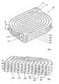
- Fig. 1 shows a perspective view of an embodiment of a wastewater heat exchanger 10 according to the invention, comprising a total of four channel molding plates 102, 104, 106 and 108. Between the channel molding plates 102, 104, 106 and 108 a total of three heat transfer plates 203, 205 and 207 are arranged, the heat transfer plate 203 between the channel molding plates 102 and 104, the heat transfer plate 205 between the channel molding plates 104 and 106, and the heat transfer plate 207 between the channel molding plates 106 and 108th
- the channel molding plates 102, 104, 106 and 108 are shaped to form a one-side open channel extending continuously and substantially spirally from an outer region or edge region of the channel molding plate 102, 104, 106, 108 into an interior region and from there again into an outer region or edge region of the channel molding plate 102, 104, 106, 108 extends.
- the open sides of the channels are closed by the heat transfer plates 203, 205 and 207, so that closed channels arise.
- the wastewater heat exchanger 10 has an inlet opening F1 for the introduction of fresh water.
- the fresh water introduced through the inlet port F1 is first led into the channel 322 formed by the channel forming plate 106 and the heat transfer plate 207.
- the fresh water then flows through the channel 324 formed by the channel molding plate 104 and the heat transfer plate 205.
- the fresh water is passed through the channel 326, which is formed by the channel plate 102 and the heat transfer plate 203.
- the fresh water is finally removed again at an outlet opening F2.
- the waste water heat exchanger 10 includes an inlet port A1 for the waste water.
- the waste water first flows through the channel 342 formed by the channel forming plate 104 and the heat transfer plate 203, subsequently through the channel 344 formed by the channel forming plate 106 and the heat transfer plate 205, and finally through the channel 346 passing through the channel forming plate 108 and the heat transfer plate 207 is formed.
- the wastewater is removed at an outlet A2 the wastewater heat exchanger.
- the channel molding plates 102, 104, 106 and 108 and the heat transfer plates 203, 205 and 207 and the inlets A1, F1 and the outlets A2, F2 are designed so that wastewater and fresh water in opposite channels in opposite directions and in directly adjacent Run channels and wastewater and fresh water and the entire wastewater heat exchanger in opposite directions, through the different levels of the channels, ie also in the vertical direction V (s. Fig. 1 ), so that fresh water, which has just been introduced through the inlet F1, flows in a channel region 322 which opposes a channel region 346 in which Wastewater is located, which has already passed through almost the entire wastewater heat exchanger. The same applies vice versa for wastewater that is being led through the inlet A1 into the wastewater heat exchanger.
- the channel molding plates 102, 104, 106 and 108 are made of PP or PA in this embodiment, while the heat transfer plates 203, 205 and 207 are made of plastic in this embodiment, wherein the plastic is provided with additives that increase the thermal conductivity.
- the heat transfer plates can also be made of metal, for example, copper.
- Fig. 3 shows an embodiment of a heat transfer plate 200, which is formed very similar to the heat transfer plates, which in the Figures 1 and 2 Therefore, identical reference numerals are used for these similar elements.
- heat transfer plate 200 is a heat transfer plate made of stainless steel, which has a thickness of 0.3 mm. Again, it is of course possible that alternatively a heat transfer plate made of plastic with thermal conductivity increasing additives is used.
- the heat transfer plate 200 has two openings 220 and 240, can pass through the wastewater or fresh water to pass through all the channel formed by the channel molding plates and the heat transfer plates channel or channels of the wastewater heat exchanger.
- Fig. 4 shows an embodiment of a channel molding plate 104, which in the Figures 1 and 2 shown channel molding plate 104 is very similar, so that identical reference numerals are used.
- Channel plate shown is a mold plate, which forms on both sides each one open on one side channel, wherein in the perspective view of Fig. 4 only the channel 342 is visible on one side.
- channel molding plate 104 is therefore a channel molding plate, which in a multi-layer wastewater heat exchanger, such as in Fig. 1 and Fig. 2 is shown, and is used there in an indoor area.
- Fig. 5 shows a perspective view of another channel molding plate 108, which in the Figs. 1 and 2 shown channel plate 108 is very similar and can also be used in a multi-layer wastewater heat exchanger.
- a channel molding plate 108 is such a channel molding plate, in which only one side of a channel 346 is formed.
- channel plate 108 is therefore suitable both for a multi-layer wastewater heat exchanger, as in the Fig. 1 and 2 is shown, in this case, for a channel molding plate, which is used in a peripheral region of the waste water heat exchanger as the end plate, also suitable in Fig. 5 also shown channel plate for a smaller wastewater heat exchanger, for example, consists of only two channel plates, which are separated by a heat transfer plate.
Abstract
Description
Die vorliegende Erfindung betrifft einen Abwasserwärmetauscher für Geschirrspülmaschinen, insbesondere für gewerbliche Geschirrspülmaschinen, sowie eine Geschirrspülmaschine mit einem solchen Abwasserwärmetauscher.The present invention relates to a waste water heat exchanger for dishwashers, in particular for commercial dishwashers, and a dishwasher with such a waste water heat exchanger.
Beim Betrieb von Geschirrspülmaschinen muss Spülwasser für das Spülen des Geschirrs erwärmt werden, gleichzeitig wird noch erwärmtes Abwasser abgeführt, damit dieses entweder entsorgt oder aufbereitet wird.When operating dishwashers, rinsing water for dishwashing must be heated, while at the same time heated waste water is being removed so that it is either disposed of or treated.
Es ist daher bekannt, in Geschirrspülmaschinen Wärmetauscher einzusetzen, s. beispielsweise die
Diese Aufgabe wird durch einen Abwasserwärmetauscher für Geschirrspülmaschinen gemäß Anspruch 1 und eine Geschirrspülmaschine mit einem solchen Abwasserwärmetauscher gemäß Anspruch 9 gelöst. Die Ansprüche 2 bis 8 betreffen jeweils vorteilhafte Ausführungsformen des erfindungsgemäßen Abwasserwärmetauschers für Geschirrspülmaschinen.This object is achieved by a waste heat exchanger for dishwashers according to claim 1 and a dishwasher with such a waste water heat exchanger according to claim 9.
Erfindungsgemäß umfasst der Abwasserwärmetauscher mindestens zwei Kanalformplatten und mindestens eine Wärmeübergangsplatte. Die mindestens zwei Kanalformplatten bestehen aus einem Kunststoffmaterial, während die Wärmeübergangsplatte aus einem metallischen Material oder einem wärmeleitfähigen Kunststoff-Werkstoff, insbesondere einem Kunststoff, dem Additive, insbesondere metallische Additive, zugesetzt sind. Ein wärmeleitfähiger Kunststoff oder ein Kunststoff mit erhöhter Wärmeleitfähigkeit im Sinne dieser Erfindung umfasst insbesondere Kunststoffe mit einer Wärmeleitfähigkeit von 1,0 W/(m*K) bis 10 W/(m*k), bevorzugt Kunststoffe mit Wärmeleitfähigkeiten von 5,0 W/(m*K) bis 10 W/(m*K).According to the invention, the wastewater heat exchanger comprises at least two channel molding plates and at least one heat transfer plate. The at least two channel molding plates are made of a plastic material, while the heat transfer plate of a metallic material or a thermally conductive plastic material, in particular a plastic, the additives, in particular metallic additives, are added. A thermally conductive plastic or a plastic with increased thermal conductivity in the context of this invention comprises in particular plastics with a thermal conductivity of 1.0 W / (m * K) to 10 W / (m * k), preferably plastics with thermal conductivities of 5.0 W / (m * K) to 10 W / (m * K).
Im Falle eines Kunststoffes mit erhöhter Wärmeleitfähigkeit wird bevorzugt PP (Polypropylen) eingesetzt. Die Wärmeleitfähigkeit von PP, PA (Polyamid) oder ähnlichen Kunststoffen ist normalerweise ca. 0,2 W/(m*K). Durch Additive, wie beispielsweise Aluminiumoxyd, Magnesiumoxyd, Graphit, Aluminiumnitrid oder Bornitrid, können deutlich höhere Werte erreicht werden. Ein Additiv wird dem Kunststoffgranulat vor dem Verarbeiten (Spritzen) zugesetzt. Es werden Wärmeleitfähigkeiten von 1, 0 (W/(m*K) bis 10 W/(m*K) erreicht, was einer Erhöhung der Wärmeleitfähigkeit um einen Faktor von 5 bis 50 im Vergleich zu normalem PP bedeutet.In the case of a plastic with increased thermal conductivity, preference is given to using PP (polypropylene). The thermal conductivity of PP, PA (polyamide) or similar plastics is normally about 0.2 W / (m * K). By additives, such as aluminum oxide, magnesium oxide, graphite, aluminum nitride or boron nitride, significantly higher values can be achieved. An additive is added to the plastic granules prior to processing (spraying). Thermal conductivities of 1, 0 (W / (m * K) to 10 W / (m * K) are achieved, which means an increase of the thermal conductivity by a factor of 5 to 50 compared to normal PP.
Der Begriff "metallisches Material" im Sinne dieser Erfindung umfasst alle Metalle, Halbmetalle sowie Legierungen und intermetallische Phasen sowie Materialien, die eine metallische Bindung eingehen. Solche Materialien zeichnen sich durch eine hohe Wärmeleitfähigkeit aus.The term "metallic material" for the purposes of this invention includes all metals, semimetals and alloys and intermetallic phases, as well as materials that undergo a metallic bond. Such materials are characterized by a high thermal conductivity.
Der Begriff "Kunststoffmaterial" umfasst unter anderem Materialien, deren Grundbestandteil synthetisch oder halbsynthetisch aus monomeren organischen Molekülen hergestellt ist.The term "plastic material" includes, inter alia, materials whose basic component is synthetically or semi-synthetically prepared from monomeric organic molecules.
Der Begriff Kunststoffmaterial im Sinne dieser Erfindung umfasst insbesondere Thermoplaste, Duroplaste, Elastomere und thermoplastische Elastomere.The term plastic material in the context of this invention includes in particular thermoplastics, thermosets, elastomers and thermoplastic elastomers.
Eine Kanalformplatte weist auf mindestens einer Seite der Kanalformplatte einen auf einer Seite offenen, insbesondere kontinuierlich verlaufenden, Kanal auf, der sich bevorzugt von einem Außenbereich oder Randbereich der Kanalformplatte in einen Innenbereich und von dort wieder in einen Außenbereich oder Randbereich der Kanalformplatte erstreckt. Der Kanal hat an einem Ende eine Einlassöffnung und an seinem anderen Ende eine Auslassöffnung, so dass ein fließfähiges Medium, insbesondere Frischwasser einerseits und Abwasser andererseits, an der Einlassöffnung in den Kanal eingeleitet werden kann, den Kanal durchlaufen bzw. durchfließen kann und an der Auslassöffnung wieder ausgeleitet werden kann.A channel molding plate has on at least one side of the channel molding plate on one side open, in particular continuously extending channel, which preferably extends from an outer region or edge region of the channel molding plate in an inner region and from there again in an outer region or edge region of the channel molding plate. The channel has an inlet opening at one end and an outlet opening at its other end, so that a flowable medium, in particular fresh water on the one hand and sewage on the other hand, can be introduced into the channel at the inlet opening, through the channel and through the outlet opening can be discharged again.
Je nach Aufbau des Abwasserwärmetauschers werden Kanalformplatten eingesetzt, die nur auf einer Seite einen Kanal ausbilden, oder Kanalformplatten, die auf ihren beiden Seiten einen Kanal bilden. Kanalformplatten, die auf beiden Seiten einen Kanal bilden, werden insbesondere dann verwendet, wenn ein größer dimensionierter Abwasserwärmetauscher benötigt wird, wobei diese Kanalformplatten dann in einem Innenbereich des Abwasserwärmetauschers bzw. als Zwischenplatten verwendet werden. Kanalformplatten mit einem Kanal auf nur einer Seite werden insbesondere bei kleiner dimensionierten Abwasserwärmetauschern oder aber auch bei größer dimensionierten Abwasserwärmetauschern als sogenannte Abschlussplatten verwendet, die die oben genannten Zwischenplatten in einer Sandwich-Bauweise einschließen.Depending on the structure of the wastewater heat exchanger duct plates are used, which form a channel only on one side, or channel molding plates, which form a channel on both sides. Channel molding plates, which form a channel on both sides, are used in particular when a larger-sized wastewater heat exchanger is required, these channel molding plates are then used in an inner region of the wastewater heat exchanger or as intermediate plates. Channel molding plates with a channel on only one side are used as so-called end plates, which include the above-mentioned intermediate plates in a sandwich construction, especially in smaller-dimensioned wastewater heat exchangers or even larger-sized wastewater heat exchangers.
Die Kanalformplatten und die Wärmeübergangsplatte bzw. die Wärmeübergangsplatten werden so angeordnet, dass die offene Seite eines Kanals einer ersten Kanalformplatte der offenen Seite eines Kanals einer zweiten Wärmeformplatte zugewandt ist, wobei die offene Seite der beiden Kanäle durch eine Wärmeübergangsplatte, die zwischen den beiden Kanalformplatten angeordnet ist, voneinander getrennt sind. Die auf einer Seite offenen Kanäle der Kanalformplatten werden daher durch die Wärmeübergangsplatte abgeschlossen.The channel molding plates and the heat transfer plate (s) are arranged such that the open side of a channel of a first channel molding plate faces the open side of a channel of a second thermoforming plate, the open side of the two channels being disposed through a heat transfer plate disposed between the two channel molding plates is, are separated from each other. The open on one side channels of the channel molding plates are therefore completed by the heat transfer plate.
Durch einen Abwasserwärmetauscher gemäß der vorliegenden Erfindung werden daher zwei Kanäle realisiert, ein Kanal für ein erstes Fluid, typischerweise Frischwasser, und ein Kanal für ein zweites Fluid, typischerweise Abwasser, wobei sich diese zwei Kanäle sehr eng gegenüberliegen und wobei diese beiden Kanäle durch die Wärmeübergangsplatte, die sehr gut wärmeleitfähig ist, voneinander getrennt sind.By a wastewater heat exchanger according to the present invention, therefore, two channels are realized, a channel for a first fluid, typically fresh water, and a channel for a second fluid, typically wastewater, these two channels being very close to each other and these two channels passing through the heat transfer plate , which is very good thermal conductivity, are separated from each other.
Der Abwasserwärmetauscher der vorliegenden Erfindung hat insbesondere den Vorteil, dass er zum einen sehr kostengünstig hergestellt werden kann, zum anderen hat er den Vorteil, dass die Kanalformplatten einerseits und die Wärmeübergangsplatte oder die Wärmeübergangsplatten andererseits sowohl mit Hinblick auf ihre Struktur als auch im Hinblick auf ihre Materialwahl optimal an ihre gewünschte Funktion angepasst werden können.The wastewater heat exchanger of the present invention has the particular advantage that it can be made very cost-effective, on the other hand, it has the advantage that the channel molding plates on the one hand and the heat transfer plate or the heat transfer plates on the other hand, both in terms of their structure and in terms of their Material selection can be optimally adapted to their desired function.
Die Kanalformplatten bilden die Strukturen, die für die Bildung der Kanäle erforderlich sind, und sie müssen daher eine gewisse Formstabilität und damit eine gewisse Materialdicke aufweisen. Die Kanalformplatten sind daher erfindungsgemäß aus Kunststoff hergestellt, da es sich bei Kunststoff um ein relativ leichtes Material handelt, das, selbst bei dickeren Wandstärken, kostengünstig, vorzugsweise im Spritzgussverfahren, hergestellt werden kann, ohne dass das Gesamtgewicht zu groß wird, während die Wärmeleitfähigkeit aufgrund der erfindungsgemäßen Struktur nicht berücksichtigt werden braucht.The channel molding plates form the structures that are required for the formation of the channels, and they must therefore have a certain dimensional stability and thus a certain material thickness. The channel molding plates are therefore made according to the invention of plastic, since it is a relatively light material in plastic, even at thicker wall thicknesses, cost, preferably by injection molding, can be produced without the total weight is too large, while the thermal conductivity due the structure of the invention need not be considered.
Auf der anderen Seite sind die Wärmeübergangsplatte oder die Wärmeübergangsplatten aus einem metallischen Material oder aus einem wärmeleitendem Kunststoff oder einem Kunststoff mit erhöhter Wärmeleitfähigkeit, insbesondere einem Kunststoff mit metallischen Additiven, hergestellt, so dass eine sehr hohe Wärmeleitfähigkeit zur Verfügung gestellt wird. Dies ist besonders vorteilhaft, weil die Wärmeübertragung von einem Kanal zu einem anderen Kanal über diese Wärmeübergangsplatte und nur im geringeren Maße durch die Kanalformplatten erfolgt, die aufgrund ihres Kunststoffmaterials und der erforderlichen Dicke des Materials, um die oben genannte Formstabilität zu gewährleisten, eine geringere Wärmeleitfähigkeit aufweisen.On the other hand, the heat transfer plate or the heat transfer plates made of a metallic material or a thermally conductive plastic or a plastic with increased thermal conductivity, in particular a plastic with metallic additives, so that a very high thermal conductivity is provided. This is particularly advantageous because heat transfer from one channel to another channel occurs through this heat transfer plate and only to a lesser extent through the channel die plates which, due to their plastic material and the required thickness of the material to provide the dimensional stability noted above, have lower thermal conductivity exhibit.
Da aufgrund der Struktur und des Aufbaus des Abwasserwärmetauschers gemäß der vorliegenden Erfmdung die Wärmeübergangsplatten keinerlei eigenständige Formstabilität aufzuweisen brauchen, vielmehr lediglich eine Trennschicht zwischen den Kanälen, die von den Kanalformplatten gebildet werden, darstellen, können diese Wärmeübergangsplatten sehr dünn ausgebildet werden, so dass sowohl Kosten als auch Gewicht minimal gehalten werden, gleichzeitig eine maximale Wärmeleitfähigkeit und damit eine maximale Effizienz des Wärmetauschers zur Verfügung gestellt wird.Since, due to the structure and construction of the waste heat exchanger according to the present invention, the heat transfer plates need not have any inherent dimensional stability, but merely constitute a separating layer between the channels formed by the channel molding plates, these heat transfer plates can be made very thin, so that both costs As well as weight are minimized, at the same time a maximum thermal conductivity and thus a maximum efficiency of the heat exchanger is provided.
Die besondere Struktur und der Aufbau des erfindungsgemäßen Abwasserwärmetauschers führen daher zu optimalen Ergebnissen im Hinblick auf den Austausch von Wärme zwischen zwei Fluiden, Abwasser und Frischwasser, wobei gleichzeitig Kosten und Gewicht sehr gering gehalten werden.The particular structure and construction of the wastewater heat exchanger according to the invention therefore lead to optimal results in terms of the exchange of heat between two fluids, wastewater and fresh water, at the same time costs and weight are kept very low.
Bei einer bevorzugten Ausführungsform sind die Kanalformplatten so ausgebildet, dass ein im wesentlichen spiralförmiger Kanal entsteht, wobei die Spiralform nahezu kreisförmig ausgebildet sein kann, aber auch eine gestrecktere oder ovale Form aufweisen kann. Es ist besonders bevorzugt, die Krümmung der Spirale möglichst gleichmäßig zu ändern und insbesondere keine Kanten oder Ecken in den Kanälen vorzusehen, da dies die Strömung der Fluide, Abwasser und Frischwasser, behindern kann. Die Form der spiralförmigen Kanäle, gleichsam als Doppelspirale, kann insbesondere an die Querschnittsform der Kanalformplatte bzw. der Wärmeübergangsplatten angepasst sein, wobei sowohl im wesentlichen kreisförmige oder ovale Kanalformplatten und Wärmeübergangsplatten vorgesehen sein können, oder auch eher rechteckige Querschnittsformen vorgesehen sein können, insbesondere mit abgerundeten Ecken. Die Gesamtform des Abwasserwärmetauschers kann dabei in weiten Bereichen an die Erfordernisse der Geschirrspülmaschine angepasst werden.In a preferred embodiment, the channel molding plates are formed so that a substantially spiral-shaped channel is formed, wherein the spiral shape may be formed nearly circular, but may also have a more straight or oval shape. It is particularly preferred to change the curvature of the spiral as evenly as possible and in particular to provide no edges or corners in the channels, as this may hinder the flow of fluids, wastewater and fresh water. The shape of the spiral channels, as a double spiral, can be adapted in particular to the cross-sectional shape of the channel plate or the heat transfer plates, both substantially circular or oval channel plates and heat transfer plates can be provided, or even rectangular cross-sectional shapes can be provided, in particular with rounded Corners. The overall shape of the wastewater heat exchanger can be adapted in many areas to the requirements of the dishwasher.
Ein besonders bevorzugter Abwasserwärmetauscher umfasst zwei Kanalformplatten, die auf ihren beiden Seiten, also auf der Vorderseite und der Rückseite, einen Kanal bilden, und zwei Kanalformplatten, die nur auf einer Seite einen Kanal bilden. Ferner umfasst ein solcher besonders bevorzugter Abwasserwärmetauscher insgesamt drei Wärmeübergangsplatten.A particularly preferred wastewater heat exchanger comprises two channel molding plates which form a channel on its two sides, that is to say on the front side and the rear side, and two channel molding plates which form a channel on only one side. Furthermore, such a particularly preferred wastewater heat exchanger comprises a total of three heat transfer plates.
Die Kanalformplatten und die Wärmeübergangsplatten sind so angeordnet, dass insgesamt drei Paar sich gegenüberliegende Kanäle gebildet werden, wobei die sich gegenüberliegenden Kanäle jeweils eines Paares durch eine Wärmeübergangsplatte voneinander getrennt sind.The channel molding plates and the heat transfer plates are arranged so that a total of three pairs of opposing channels are formed, wherein the opposite channels of each pair are separated by a heat transfer plate.
Hierdurch wird ein mehrschichtiger Abwasserwärmetauscher realisiert, so dass die effektive Gesamtlänge des Kanals bzw. der Kanäle, durch die das Frischwasser einerseits und das Abwasser andererseits fließt, verlängert wird, so dass insgesamt eine höhere Wärmeaustauschleistung realisiert wird.As a result, a multi-layer waste heat exchanger is realized, so that the effective total length of the channel or channels through which the fresh water on the one hand and the wastewater flows on the other hand is extended, so that a total of higher heat exchange performance is realized.
Die Kanalformplatten und die Wärmeübergangsplatten sind dabei so angeordnet, dass ein Fluid zuerst einen Kanal in einer ersten Kanalformplatte durchläuft, dann einen Kanal in einer zweiten Kanalformplatte und schließlich einen Kanal in einer dritten Kanalformplatte, wobei dies für beide Fluide, also das Abwasser und das Frischwasser, gilt.The channel molding plates and the heat transfer plates are arranged so that a fluid first passes through a channel in a first channel plate shape, then a channel in a second channel plate and finally a channel in a third channel plate form, for both fluids, so the waste water and the fresh water , applies.
Alternativ ist es auch möglich, einen Abwasserwärmetauscher mit nur einer Kanalformplatte, die auf beiden Seiten einen Kanal bildet, und zwei Kanalformplatten, die nur auf einer Seite einen Kanal bilden, zur Verfügung zu stellen. Ferner ist es auch möglich, Abwasserwärmetauscher mit drei oder mehr Kanalformplatten zur Verfügung zu stellen, die auf beiden Seiten einen Kanal bilden, um die Wärmeaustauschleistung des Abwasserwärmetauschers noch zu erhöhen.Alternatively, it is also possible to provide a waste water heat exchanger with only one channel molding plate, which forms a channel on both sides, and two channel molding plates, which form a channel only on one side. Further, it is also possible to provide waste heat exchangers having three or more channel molding plates which form a channel on both sides to further increase the heat exchange performance of the wastewater heat exchanger.
Der Abwasserwärmetauscher der vorliegenden Erfindung ist daher modular aufgebaut und kann, mit sehr wenigen, unterschiedlichen Bauteilen, sehr flexibel angepasst bzw. erweitert werden, was ein weiterer Vorteil des Abwasserwärmetauschers gemäß der vorliegenden Erfindung ist.The wastewater heat exchanger of the present invention is therefore modular in design and, with very few, different components, can be adapted or extended very flexibly, which is a further advantage of the wastewater heat exchanger according to the present invention.
Entscheidend ist bei dem modularen Aufbau jedoch, dass grundsätzlich zwei verschiedene Arten von Bauteilen, bevorzugt aus zwei unterschiedlichen Materialien, vorhanden sind, nämlich einerseits die Kanalformplatten aus Kunststoff, die insbesondere die Formstabilität und Struktur vorgeben und stabil genug sind, diese Struktur zu halten, und andererseits die Wärmeübergangsplatten, die aus Metall oder einem Kunststoff mit erhöhter Wärmeleitfähigkeit hergestellt sind und die sehr dünn ausgebildet sein können, um eine maximale Wärmeübertragung zu ermöglichen, ohne dass besondere Strukturgebungsansprüche an diese Wärmeübergangsplatten gestellt werden. Die oben beschriebenen Vorteile sind mit einem Wärmetauscher, auch mit einem Plattenwärmetauscher, der im wesentlichen aus identischen Bauteilen aufgebaut ist, nicht erreichbar.However, it is crucial in the modular structure that basically two different types of components, preferably of two different materials, are present, namely on the one hand the channel molding plates made of plastic, which in particular dictate the dimensional stability and structure and are stable enough to hold this structure, and on the other hand, the heat transfer plates, which are made of metal or a plastic with increased thermal conductivity and which can be made very thin, to allow maximum heat transfer, without special structural claims are made of these heat transfer plates. The advantages described above are not attainable with a heat exchanger, even with a plate heat exchanger, which is composed essentially of identical components.
Insbesondere ist zu beachten, dass bei dem Abwasserwärmetauscher gemäß der vorliegenden Erfindung, unabhängig von der Dimensionierung, also unabhängig davon, ob nur zwei Kanalformplatten und eine Wärmeübergangsplatte oder aber mehr Kanalformplatten und mehr Wärmeübergangsplatten verwendet werden, die Wärmeübergangsplatte bzw. die Wärmeübergangsplatten immer in einem Innenbereich angeordnet sind, also grundsätzlich auf beiden Seiten von Kanalformplatten umgeben sind, die eine notwendige Formstruktur geben und die Wärmeübergangsplatten auch vor möglichen Stößen und Beschädigungen von außen schützen.In particular, it should be noted that in the wastewater heat exchanger according to the present invention, regardless of the dimensioning, ie regardless of whether only two channel molding plates and a heat transfer plate or more channel molding plates and more heat transfer plates are used, the heat transfer plate or the heat transfer plates always in an interior are arranged, so basically surrounded on both sides of channel molding plates, which give a necessary shape structure and protect the heat transfer plates from possible shocks and damage from the outside.
Bei einer bevorzugten Ausführungsform sind die Kanalformplatten und die Wärmeübergangsplatten miteinander verklebt, insbesondere verpresst und verklebt, was eine besonders einfache und damit kostengünstige Herstellung ermöglicht. Auch können die Platten bspw. verschweisst werden, wenn alle Platten aus Kunststoff sind.In a preferred embodiment, the channel molding plates and the heat transfer plates are glued together, in particular pressed and glued, which allows a particularly simple and therefore cost-effective production. Also, the plates can, for example, be welded, if all plates are made of plastic.
Die Kanalformplatten sind bevorzugt in einem Spritzgussverfahren hergestellt, wobei als Material insbesondere Polypropylen (PP), Polyamid (PA) oder ähnliche Materialien geeignet sind. Als Material für die Wärmeübergangsplatten eignen sich Materialien mit höherer Leitfähigkeit als PP oder PA, insbesondere Kupfer, Edelstahl oder Kunststoffe mit leitfähigkeitssteigernden Additiven, die eine sehr hohe Wärmeleitfähigkeit besitzen, oder auch Legierungen.The channel molding plates are preferably produced in an injection molding process, wherein as a material in particular polypropylene (PP), polyamide (PA) or similar materials are suitable. Suitable materials for the heat transfer plates are materials with higher conductivity than PP or PA, in particular copper, stainless steel or plastics with conductivity-increasing additives, which have a very high thermal conductivity, or even alloys.
Aufgrund der vorteilhaften Struktur des erfindungsgemäßen Abwasserwärmetauschers können die Wärmeübergangsplatten sehr dünn ausgebildet sein, bevorzugt haben die Wärmeübergangsplatten eine Dicke von 0,1 mm bis 1,5 mm, besonders bevorzugt von 0,2 mm bis 0,8 mm, ferner bevorzugt 0,4 mm bis 0,6 mm und insbesondere von 0,2 mm bis 0,4 mm.Due to the advantageous structure of the wastewater heat exchanger according to the invention, the heat transfer plates can be made very thin, preferably the heat transfer plates have a thickness of 0.1 mm to 1.5 mm, more preferably from 0.2 mm to 0.8 mm, further preferably 0.4 mm to 0.6 mm and in particular from 0.2 mm to 0.4 mm.
Die Erfindung betrifft ferner eine Geschirrspülmaschine, insbesondere eine gewerbliche Geschirrspülmaschine, mit einem Abwasserwärmetauscher, wie er oben beschrieben worden ist.The invention further relates to a dishwasher, in particular a commercial dishwasher, with a waste water heat exchanger, as has been described above.
Diese und weitere Vorteile und Merkmale der Erfindung werden anhand der nachfolgend dargestellten besonderen Ausführungsform noch deutlicher. Es zeigen:
- Fig. 1
- eine perspektivische Ansicht einer Ausführungsform eines erfindungsgemäßen Abwasserwärmetauschers;
- Fig. 2
- eine teilweise geschnittene, perspektivische Ansicht der in
Fig. 1 gezeigten Ausführungsform des Abwassertauschers gemäß der vorliegenden Erfindung; - Fig. 3
- eine perspektivische Ansicht einer Ausführungsform einer Wärmeübergangsplatte, wie sie in einem Abwasserwärmetauscher gemäß der vorliegenden Erfindung eingesetzt werden kann;
- Fig. 4
- eine Ausführungsform einer Kanalformplatte, wie sie in einem erfindungsgemäßen Abwasserwärmetauscher eingesetzt werden kann;
- Fig. 5
- eine weitere Ausführungsform einer Kanalformplatte, wie sie in einem erfindungsgemäßen Abwasserwärmetauscher, beispielsweise in der in den
Fig. 1 und 2 gezeigten Ausführungsform, eingesetzt werden kann.
- Fig. 1
- a perspective view of an embodiment of a wastewater heat exchanger according to the invention;
- Fig. 2
- a partially sectioned, perspective view of the in
Fig. 1 shown embodiment of the wastewater exchanger according to the present invention; - Fig. 3
- a perspective view of an embodiment of a heat transfer plate, as it can be used in a wastewater heat exchanger according to the present invention;
- Fig. 4
- an embodiment of a channel molding plate, as it can be used in a wastewater heat exchanger according to the invention;
- Fig. 5
- a further embodiment of a channel molding plate, as used in a wastewater heat exchanger according to the invention, for example in the in the
Fig. 1 and 2 shown embodiment, can be used.
Wie insbesondere in den
Die offenen Seiten der Kanäle werden durch die Wärmeübergangsplatten 203, 205 und 207 geschlossen, so dass geschlossene Kanäle entstehen.The open sides of the channels are closed by the
Der Abwasserwärmetauscher 10 hat eine Einlassöffnung F1 für das Einleiten von Frischwasser. Das durch die Einlassöffnung F1 eingeleitete Frischwasser wird zuerst in den Kanal 322 geleitet, der durch die Kanalformplatte 106 und die Wärmeübergangsplatte 207 gebildet wird. Das Frischwasser fließt dann durch den Kanal 324, der von der Kanalformplatte 104 und der Wärmeübergangsplatte 205 gebildet wird. Schließlich wird das Frischwasser durch den Kanal 326 geleitet, der von der Kanalformplatte 102 und der Wärmeübergangsplatte 203 gebildet wird. Das Frischwasser wird schließlich an einer Auslassöffnung F2 wieder entnommen.The
Ferner umfasst der Abwasserwärmetauscher 10 eine Einlassöffnung A1 für das Abwasser. Das Abwasser fließt zuerst durch den Kanal 342, der von der Kanalformplatte 104 und der Wärmeübergangsplatte 203 gebildet wird, nachfolgend durch den Kanal 344, der von der Kanalformplatte 106 und der Wärmeübergangsplatte 205 gebildet wird, und abschließend durch den Kanal 346, der durch die Kanalformplatte 108 und die Wärmeübergangsplatte 207 gebildet wird. Das Abwasser wird an einem Auslass A2 dem Abwasserwärmetauscher entnommen.Further, the waste
Die Kanalformplatten 102, 104, 106 und 108 und die Wärmeübergangsplatten 203, 205 und 207 sowie die Einlässe A1, F1 und die Auslässe A2, F2 sind dabei so ausgebildet, dass Abwasser und Frischwasser in sich gegenüberliegenden Kanälen in entgegengesetzte Richtungen und in direkt aneinander angrenzenden Kanälen verlaufen, wobei Abwasser und Frischwasser auch den gesamten Abwasserwärmetauscher in entgegengesetzten Richtungen, durch die verschiedenen Ebenen der Kanäle, also auch in vertikaler Richtung V (s.
Die Kanalformplatten 102, 104, 106 und 108 sind bei dieser Ausführungsform aus PP oder PA hergestellt, während die Wärmeübergangsplatten 203, 205 und 207 bei dieser Ausführungsform aus Kunststoff hergestellt sind, wobei der Kunststoff mit Additiven versehen ist, die die Wärmeleitfähigkeit erhöhen. Alternativ können die Wärmeübergangsplatten auch aus Metall hergestellt sein, beispielsweise auch aus Kupfer.The
Wie deutlich in
Bei der in
Die in
Werden die in den
Die in der vorstehenden Beschreibung, den Ansprüchen und den Zeichnungen offenbarten Merkmale können sowohl einzeln als auch in beliebiger Kombination für die Ausführung der Erfindung in ihren verschiedenen Ausgestaltungen von Bedeutung sein.The features disclosed in the foregoing description, claims and drawings may be significant to the practice of the invention in its various forms both individually and in any combination thereof.
Claims (11)
wobei die mindestens zwei Kanalformplatten (102, 104, 106, 108) aus einem Kunststoffmaterial hergestellt sind und jede Kanalformplatte (102, 104, 106, 108) auf mindestens einer Seite der Kanalformplatte (102, 104, 106, 108) einen auf einer Seite offenen Kanal (322, 324, 326; 342, 344, 346) bildet,
wobei der Kanal (322, 324, 326; 342, 344, 346) an einem Ende eine Einlassöffnung und an seinem anderen Ende eine Auslassöffnung aufweist, und
wobei die mindestens eine Wärmeübergangsplatte (203, 205, 207) aus einem metallischen Material oder aus einem wärmeleitfähigen Kunststoff hergestellt ist, und wobei die mindestens zwei Kanalformplatten (102, 104, 106, 108) und die mindestens eine Wärmeübergangsplatte (203, 205, 207) so angeordnet sind, dass die offene Seite eines Kanals einer ersten Kanalformplatte der offenen Seite eines Kanals einer zweiten Kanalformplatte zugewandt ist, wobei die offenen Seiten der beiden Kanäle durch eine Wärmeübergangsplatte, die zwischen den beiden Kanalformplatten angeordnet ist, abgeschlossen sind.Wastewater heat exchanger (10) for dishwashers, in particular commercial dishwashers, comprising at least two channel forming plates (102, 104, 106, 108) and at least one heat transfer plate (203, 205, 207),
wherein the at least two channel molding plates (102, 104, 106, 108) are made of a plastic material and each channel molding plate (102, 104, 106, 108) on at least one side of the channel molding plate (102, 104, 106, 108) one on one side open channel (322, 324, 326, 342, 344, 346),
wherein the channel (322, 324, 326; 342, 344, 346) has an inlet opening at one end and an outlet opening at its other end, and
wherein the at least one heat transfer plate (203, 205, 207) is made of a metallic material or of a thermally conductive plastic, and wherein the at least two channel molding plates (102, 104, 106, 108) and the at least one heat transfer plate (203, 205, 207 ) are arranged such that the open side of a channel of a first channel molding plate faces the open side of a channel of a second channel molding plate, wherein the open sides of the two channels are closed by a heat transfer plate disposed between the two channel molding plates.
Applications Claiming Priority (1)
| Application Number | Priority Date | Filing Date | Title |
|---|---|---|---|
| DE102012000455 | 2012-01-12 |
Publications (2)
| Publication Number | Publication Date |
|---|---|
| EP2614764A2 true EP2614764A2 (en) | 2013-07-17 |
| EP2614764A3 EP2614764A3 (en) | 2017-03-29 |
Family
ID=47623921
Family Applications (1)
| Application Number | Title | Priority Date | Filing Date |
|---|---|---|---|
| EP13150953.1A Withdrawn EP2614764A3 (en) | 2012-01-12 | 2013-01-11 | Waste water heat exchanger for a dishwasher and dishwasher |
Country Status (1)
| Country | Link |
|---|---|
| EP (1) | EP2614764A3 (en) |
Cited By (9)
| Publication number | Priority date | Publication date | Assignee | Title |
|---|---|---|---|---|
| US9289107B2 (en) | 2011-12-13 | 2016-03-22 | Ecolab Usa Inc. | Dishmachine |
| WO2016048945A1 (en) * | 2014-09-22 | 2016-03-31 | Illinois Tool Works Inc. | Warewasher with drain water tempering system with energy recovery using plate exchangers |
| EP3074710A4 (en) * | 2013-11-29 | 2017-08-23 | Limited Cyclotec | Heat exchanger |
| WO2017150975A1 (en) * | 2016-03-01 | 2017-09-08 | Level Holding B.V. | Recuperator, parts of which are manufactured by injection moulding |
| US10610081B2 (en) | 2014-09-02 | 2020-04-07 | Illinois Tool Works Inc. | Dishwasher having a liquid transportation line |
| EP3988884A1 (en) * | 2020-10-20 | 2022-04-27 | Haier Deutschland GmbH | Dishwasher |
| WO2022180151A1 (en) * | 2021-02-25 | 2022-09-01 | Dutch Innovation In Air Treatment Bv | Process to manufacture an interconnected stack of thermoplastic frames |
| EP4261487A1 (en) | 2022-04-13 | 2023-10-18 | HAIER Germany GmbH | Heat exchanger unit, heat exchanger device, dishwasher, washing machine and process of manufacturing a heat exchanger unit |
| WO2024041071A1 (en) * | 2022-08-23 | 2024-02-29 | 佛山市顺德区美的洗涤电器制造有限公司 | Dishwasher |
Citations (1)
| Publication number | Priority date | Publication date | Assignee | Title |
|---|---|---|---|---|
| EP0689791A1 (en) | 1994-06-28 | 1996-01-03 | Premark Feg Corporation | Rinsing machine and heat recovery system from used water |
Family Cites Families (4)
| Publication number | Priority date | Publication date | Assignee | Title |
|---|---|---|---|---|
| GB655470A (en) * | 1948-03-08 | 1951-07-25 | Raymond Ernest Wigg | Improvements in or relating to heat exchangers |
| EP0982427B1 (en) * | 1998-08-25 | 2003-03-05 | Joma-Polytec Kunststofftechnik GmbH | Cross flow heat exchanger for laundry drier with condenser |
| DE10359573A1 (en) * | 2003-12-18 | 2005-07-28 | Robert Bosch Gmbh | Heat transfer unit for a heat exchanger |
| DE102009032370A1 (en) * | 2009-07-08 | 2011-01-13 | Sartorius Stedim Biotech Gmbh | Plate heat exchanger |
-
2013
- 2013-01-11 EP EP13150953.1A patent/EP2614764A3/en not_active Withdrawn
Patent Citations (1)
| Publication number | Priority date | Publication date | Assignee | Title |
|---|---|---|---|---|
| EP0689791A1 (en) | 1994-06-28 | 1996-01-03 | Premark Feg Corporation | Rinsing machine and heat recovery system from used water |
Cited By (19)
| Publication number | Priority date | Publication date | Assignee | Title |
|---|---|---|---|---|
| US9289107B2 (en) | 2011-12-13 | 2016-03-22 | Ecolab Usa Inc. | Dishmachine |
| US11191419B2 (en) | 2011-12-13 | 2021-12-07 | Ecolab Usa Inc. | Dishmachine |
| US10314461B2 (en) | 2011-12-13 | 2019-06-11 | Ecolab Usa Inc. | Dishmachine |
| US10349803B2 (en) | 2011-12-13 | 2019-07-16 | Ecolab Usa Inc. | Dishmachine |
| EP3074710A4 (en) * | 2013-11-29 | 2017-08-23 | Limited Cyclotec | Heat exchanger |
| US10610081B2 (en) | 2014-09-02 | 2020-04-07 | Illinois Tool Works Inc. | Dishwasher having a liquid transportation line |
| WO2016048945A1 (en) * | 2014-09-22 | 2016-03-31 | Illinois Tool Works Inc. | Warewasher with drain water tempering system with energy recovery using plate exchangers |
| CN106714645A (en) * | 2014-09-22 | 2017-05-24 | 伊利诺斯工具制品有限公司 | Warewasher with drain water tempering system with energy recovery using plate exchangers |
| US9986886B2 (en) | 2014-09-22 | 2018-06-05 | Illinois Tool Works Inc. | Warewasher with drain water tempering system with energy recovery using plate heat exchangers |
| WO2017150975A1 (en) * | 2016-03-01 | 2017-09-08 | Level Holding B.V. | Recuperator, parts of which are manufactured by injection moulding |
| NL2016347B1 (en) * | 2016-03-01 | 2017-09-11 | Level Holding Bv | Recuperator, parts of which are made by injection molding. |
| EP3988884A1 (en) * | 2020-10-20 | 2022-04-27 | Haier Deutschland GmbH | Dishwasher |
| WO2022084279A1 (en) * | 2020-10-20 | 2022-04-28 | Haier Deutschland GmbH | Dishwasher |
| WO2022180151A1 (en) * | 2021-02-25 | 2022-09-01 | Dutch Innovation In Air Treatment Bv | Process to manufacture an interconnected stack of thermoplastic frames |
| NL2027649A (en) * | 2021-02-25 | 2022-09-20 | Dutch Innovation In Air Treat B V | Process to manufacture an interconnected stack of thermoplastic frames |
| NL2027649B1 (en) * | 2021-02-25 | 2022-09-20 | Dutch Innovation In Air Treat B V | Process to manufacture an interconnected stack of thermoplastic frames |
| EP4261487A1 (en) | 2022-04-13 | 2023-10-18 | HAIER Germany GmbH | Heat exchanger unit, heat exchanger device, dishwasher, washing machine and process of manufacturing a heat exchanger unit |
| WO2023198446A1 (en) | 2022-04-13 | 2023-10-19 | Haier Germany Gmbh | Heat exchanger unit, heat exchanger device, dishwasher, washing machine and process of manufacturing a heat exchanger unit |
| WO2024041071A1 (en) * | 2022-08-23 | 2024-02-29 | 佛山市顺德区美的洗涤电器制造有限公司 | Dishwasher |
Also Published As
| Publication number | Publication date |
|---|---|
| EP2614764A3 (en) | 2017-03-29 |
Similar Documents
| Publication | Publication Date | Title |
|---|---|---|
| EP2614764A2 (en) | Waste water heat exchanger for a dishwasher and dishwasher | |
| DE102007005370A1 (en) | heat exchangers | |
| EP1559980A1 (en) | Plate heat exchanger | |
| DE202008004582U1 (en) | Plate heat exchanger | |
| DE102010063141A1 (en) | heat exchangers | |
| DE102007011762A1 (en) | Heat exchangers, in particular oil coolers for motor vehicles | |
| DE102012217871A1 (en) | Heat exchanger | |
| DE3141161A1 (en) | HEAT EXCHANGER | |
| DE102006053702B4 (en) | Heat exchangers, in particular gas coolers | |
| DE102017214822A1 (en) | HEAT EXCHANGERS | |
| DE2923944A1 (en) | PLATE HEAT EXCHANGER | |
| DE112010002307T5 (en) | heatsink | |
| DE10061949A1 (en) | Internal combustion engine exhaust gas heat exchanger involves exhaust gas recirculation system cooler with core area of several small pipes through which cooling water flows and several ribs between adjacent pipes | |
| DE102017219433A1 (en) | Heat exchanger for an internal combustion engine | |
| EP1687579B1 (en) | Charge-air/coolant cooler | |
| DE102015115261A1 (en) | Cooling device with a liquid heat sink | |
| DE102009014936A1 (en) | Wastewater pipe with a fresh water and heat exchanger | |
| DE202017102436U1 (en) | Heat exchanger with microchannel structure or wing tube structure | |
| EP2167895A1 (en) | Heat exchanger | |
| DE2119872A1 (en) | Guide plate for shell and tube heat exchanger | |
| DE2637511B2 (en) | Heat exchanger or heat exchange wall | |
| EP3239641A1 (en) | Flat tube for a heat exchanger | |
| DE202017104743U1 (en) | Heat exchanger with microchannel structure or wing tube structure | |
| DE102018207640A1 (en) | cooling structure | |
| EP2899487B1 (en) | Stacked disc heat exchanger |
Legal Events
| Date | Code | Title | Description |
|---|---|---|---|
| PUAI | Public reference made under article 153(3) epc to a published international application that has entered the european phase |
Free format text: ORIGINAL CODE: 0009012 |
|
| AK | Designated contracting states |
Kind code of ref document: A2 Designated state(s): AL AT BE BG CH CY CZ DE DK EE ES FI FR GB GR HR HU IE IS IT LI LT LU LV MC MK MT NL NO PL PT RO RS SE SI SK SM TR |
|
| AX | Request for extension of the european patent |
Extension state: BA ME |
|
| PUAL | Search report despatched |
Free format text: ORIGINAL CODE: 0009013 |
|
| AK | Designated contracting states |
Kind code of ref document: A3 Designated state(s): AL AT BE BG CH CY CZ DE DK EE ES FI FR GB GR HR HU IE IS IT LI LT LU LV MC MK MT NL NO PL PT RO RS SE SI SK SM TR |
|
| AX | Request for extension of the european patent |
Extension state: BA ME |
|
| RIC1 | Information provided on ipc code assigned before grant |
Ipc: F28D 21/00 20060101ALI20170223BHEP Ipc: F28D 9/00 20060101ALI20170223BHEP Ipc: F28F 21/06 20060101ALI20170223BHEP Ipc: A47L 15/42 20060101AFI20170223BHEP |
|
| STAA | Information on the status of an ep patent application or granted ep patent |
Free format text: STATUS: THE APPLICATION HAS BEEN WITHDRAWN |
|
| 18W | Application withdrawn |
Effective date: 20170531 |