EP2612996A1 - Vorrichtung und Verfahren zur Ausrichtung von Spitzendeckbänder - Google Patents
Vorrichtung und Verfahren zur Ausrichtung von Spitzendeckbänder Download PDFInfo
- Publication number
- EP2612996A1 EP2612996A1 EP12198326.6A EP12198326A EP2612996A1 EP 2612996 A1 EP2612996 A1 EP 2612996A1 EP 12198326 A EP12198326 A EP 12198326A EP 2612996 A1 EP2612996 A1 EP 2612996A1
- Authority
- EP
- European Patent Office
- Prior art keywords
- platform
- projection
- tip
- alignment feature
- shrouds
- Prior art date
- Legal status (The legal status is an assumption and is not a legal conclusion. Google has not performed a legal analysis and makes no representation as to the accuracy of the status listed.)
- Withdrawn
Links
Images


Classifications
-
- F—MECHANICAL ENGINEERING; LIGHTING; HEATING; WEAPONS; BLASTING
- F01—MACHINES OR ENGINES IN GENERAL; ENGINE PLANTS IN GENERAL; STEAM ENGINES
- F01D—NON-POSITIVE DISPLACEMENT MACHINES OR ENGINES, e.g. STEAM TURBINES
- F01D5/00—Blades; Blade-carrying members; Heating, heat-insulating, cooling or antivibration means on the blades or the members
- F01D5/12—Blades
- F01D5/22—Blade-to-blade connections, e.g. for damping vibrations
- F01D5/225—Blade-to-blade connections, e.g. for damping vibrations by shrouding
-
- Y—GENERAL TAGGING OF NEW TECHNOLOGICAL DEVELOPMENTS; GENERAL TAGGING OF CROSS-SECTIONAL TECHNOLOGIES SPANNING OVER SEVERAL SECTIONS OF THE IPC; TECHNICAL SUBJECTS COVERED BY FORMER USPC CROSS-REFERENCE ART COLLECTIONS [XRACs] AND DIGESTS
- Y02—TECHNOLOGIES OR APPLICATIONS FOR MITIGATION OR ADAPTATION AGAINST CLIMATE CHANGE
- Y02T—CLIMATE CHANGE MITIGATION TECHNOLOGIES RELATED TO TRANSPORTATION
- Y02T50/00—Aeronautics or air transport
- Y02T50/60—Efficient propulsion technologies, e.g. for aircraft
-
- Y—GENERAL TAGGING OF NEW TECHNOLOGICAL DEVELOPMENTS; GENERAL TAGGING OF CROSS-SECTIONAL TECHNOLOGIES SPANNING OVER SEVERAL SECTIONS OF THE IPC; TECHNICAL SUBJECTS COVERED BY FORMER USPC CROSS-REFERENCE ART COLLECTIONS [XRACs] AND DIGESTS
- Y10—TECHNICAL SUBJECTS COVERED BY FORMER USPC
- Y10T—TECHNICAL SUBJECTS COVERED BY FORMER US CLASSIFICATION
- Y10T29/00—Metal working
- Y10T29/49—Method of mechanical manufacture
- Y10T29/49316—Impeller making
- Y10T29/4932—Turbomachine making
- Y10T29/49321—Assembling individual fluid flow interacting members, e.g., blades, vanes, buckets, on rotary support member
Definitions
- the present invention generally relates to a device and method for aligning tip shrouds in a rotary machine.
- Rotary machines including turbines are widely used in a variety of aviation, industrial, and power generation applications to perform work.
- Each rotating machine generally includes alternating stages of peripherally mounted stator vanes and rotating blades.
- the stator vanes may be attached to a stationary component such as a casing that surrounds the rotating machine, and the rotating blades may be attached to a rotor located along an axial centerline of the rotating machine.
- a compressed working fluid such as but not limited to steam, combustion gases, or air, flows along a gas path through the rotating machine to produce work.
- the stator vanes accelerate and direct the compressed working fluid onto the subsequent stage of rotating blades to impart motion to the rotating blades, thus turning the rotor and performing work.
- each rotating blade may include a tip shroud disposed at an outer radial tip of the rotating blades. As the turbine rotates and cycles through various stages of operation, the tip shrouds may form a seal at the radial tip of the turbine blades and further reduce leakage of the compressed working fluid between the radial tip of the blade and the casing.
- Tip shroud aerodynamic properties and mechanical performance are important design considerations that balance efficiency and performance on the one hand with blade life on the other hand.
- tip shrouds may reduce leakage of the working fluid, tip shrouds also generally increase the mass at the tip of the blade, which may increase creep or yield of the tip shroud. Creep or yield, in turn may reduce the life of the turbine blade, increase maintenance cost and/or extend outages.
- a tip shroud that fails may introduce debris into the gas path that may cause significant damage to the casing, downstream stators, and/or blades. As a result, continued improvements in devices and methods for aligning tip shrouds in a rotary machine would be useful.
- One embodiment of the present invention is a device for aligning tip shrouds.
- the device includes a platform configured to connect to a blade, a first projection that extends circumferentially across at least a portion of the platform, and a first complementary alignment feature on the first projection.
- a second embodiment of the present invention is a device for aligning tip shrouds.
- the device includes a first platform configured to connect to a first blade, a first projection that extends circumferentially across at least a portion of the first platform and a first alignment feature on the first projection.
- a second platform configured to connect to a second blade adjacent to the first rotary blade, a second projection that extends circumferentially across at least a portion of said second platform and a second alignment feature on said second projection, wherein the first alignment feature nests at least partially inside the second alignment feature.
- the present invention may also include a method aligning tip shrouds.
- the method includes rotating a plurality of tip shrouds, wherein each tip shroud is coupled to a blade, aligning adjacent tip shrouds by nesting a first alignment feature of a first tip shroud into a second alignment feature of a second tip shroud.
- Various embodiments of the present invention include a device and method for aligning tip shrouds in any system having a pressurized gas flow-path and rotating components, such as a compressor, a gas turbine, a steam turbine, a jet engine or any other rotary machine.
- the device and method generally includes tip shrouds that have complementary alignment features.
- the alignment features may radially, axially, and/or circumferentially align adjacent tip shrouds.
- the tip shrouds enhance the seal of the gas path and an improved seal may reduce leakage of pressurized gas around the blade radial tip, thus utilizing more of the pressurized gas to increase overall rotary machine efficiency.
- improved alignment of the tip shrouds reduce or prevent adjacent tip shrouds from overlapping and/or increase the life of individual tip shrouds further reducing maintenance cost and further increasing overall rotating machine efficiency.
- Fig. 1 provides a partial perspective view of a rotary machine blade stage 10 according to one embodiment of the present invention.
- blade may include any rotating blade utilized within a rotary machine.
- blade may include but is not limited to compressor and/or turbine blades.
- each stage 10 generally includes a plurality of adjacent blades 12 circumferentially connected to a rotor 14.
- Each blade 12 generally includes an airfoil 16 that extends radially outward from the rotor 14 and terminates at a radial tip 18.
- a casing 20 circumferentially surrounds the blade stage 10 to define a gas path 22 between the casing 20 and the rotor 14. In this manner, a pressurized working fluid may flow axially across the blades 12 to cause the blades 12, and thus the rotor 14, to rotate.
- the blade stage 10 may include a device 40 for aligning tip shrouds 42 that prevents adjacent tip shrouds 42 from overlapping.
- the device 40 may generally include one or more tip shrouds 42 configured for connection to the radial tips 18 of the blades 12.
- the tip shrouds 42 may be mechanically attached to the blades 12, such as by welding. Alternately, the tip shrouds 42 may be cast as an integral part of the blades 12 or may be machined. In this manner, adjacent tip shrouds may form a barrier at the radial tips 18 of the blades 12 as the rotary machine cycles through various operating conditions.
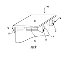
- each tip shroud 42 generally includes a platform 44 and one or more projections 46.
- the platform 44 generally includes a pair of opposed axially extending surfaces 48 and circumferentially extending surfaces 50.
- the axially extending surfaces 48 may be straight, angled or curved to provide a complementary surface for platforms 44 of adjacent tip shrouds 42.
- each platform 44 may include one or more projections 46 extending generally circumferentially across at least a portion of the platform 44 and may have a constant or varying thickness and a constant or varying radial height. As show in Fig. 2 , the one or more projections 46 may extend radially outward from the platform 44. In alternate embodiments, as shown in Fig. 3 , the one or more projections 46 may extend radially inward from the platform 44.
- each projection 46 may include complementary alignment features 52 positioned on a first or second end 54 of the projection 46 that enhance radial and/or axial alignment between adjacent tip shrouds 42.
- the complementary alignment features 52 may include, for example, male and female surfaces in the projections 46.
- the complementary alignment features may be a combination of spherical protrusions 56 and recesses 58 on opposite ends of the projections 46.
- the tip shrouds 42 may come into contact with adjacent tip shrouds due to centrifugal forces and/or thermal expansion of the tip shrouds 42.
- the spherical protrusions 56 on a first tip shroud 42 nest inside the spherical recesses 58 of a second adjacent tip shroud 42 to align adjacent tip shrouds 42 in the radial and/or axial planes.
- tip shroud platform 44 may be significantly reduced between adjacent tip shrouds 42.
- the complementary alignment features 52 may prevent adjacent platforms 44 from buckling or overlapping.
- larger tip shrouds 42 may be utilized at the radial tip 18 of blades 12 to enhance sealing of the gas path 22 without compromising blade life.
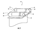
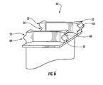
- Figs. 5-9 illustrate alternate embodiments of complementary alignment features 52 within the scope of the present invention.
- the complementary alignment features 52 may be cylindrical or angled protrusions 60, 64 and recesses 62, 66 as shown in Figs. 5 and 6 , respectively. These shapes may allow for radial alignment, radial load transfer between adjacent tip shrouds 42, and/or provide damping between adjacent blades as the turbine cycles through various operational conditions. In addition, these shapes may allow for large axial misalignment or movement between adjacent tip shrouds 42 as shown in Fig. 1 , during cold assembly of the turbine rotor or operation of the turbine.
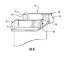
- Figs. 7 and 8 illustrate complementary alignment features 52 which may be generally polygonal, elliptical, parabolic or spherically slotted and radially open recesses 68, 72 and protrusions 70, 74 as shown in Figs. 7 and 8 respectfully.
- the slotted and radially open recesses 68, 72 may include one or more mating surfaces and an opening, and the protrusions 70, 74 may include one or more complementary mating surfaces.
- Each of these alternate embodiments may provide a larger mating surface area between the complementary alignment features 52.
- radial alignment and transfer of radial loads between adjacent tip shrouds 42 during rotary machine operation may be provided, thus preventing overlapping between adjacent tip shrouds 42, allowing for larger tip shrouds 42, and improving the gas path seal at the radial tip 18 of the blades 12.
- Fig. 9 illustrates complementary alignment features 52 which may be biscuit and/or cylindrically shaped protrusions 76 and recesses 78. As shown in Fig. 9 , biscuit shaped complementary alignment features 52 may include flat surfaces 80 and an arcuate surface 82. In addition to allowing for radial alignment and/or transfer of radial loading between adjacent tip shrouds 42 the biscuit shaped complementary alignment features 52 may constrain axial movement between adjacent tip shrouds 42 as the turbine cycles through various operating conditions, thus improving the sealing performance of adjacent tip shrouds 42.
- Figs. 1-9 may also provide a method for aligning adjacent tip shrouds 42 including rotating a plurality of tip shrouds 42 which may be coupled to a rotating blade 12, aligning adjacent tip shrouds 42 by nesting a first alignment feature 52 of a first tip shroud 42 into a second alignment feature 52 of a second tip shroud 42.
- the method may further comprise nesting a third alignment feature 52 of the first tip 42 shroud into a fourth alignment feature 52 of the second tip 42 shroud.
- This method may create a gas path seal at the radial tip 18 of adjacent blades 12, thus inhibiting pressurized working fluid leakage over the radial tip 18 of the blades 12 and preventing overlapping of adjacent tip shrouds 42.
- larger tip shrouds 42 may be designed and blade 12 life may be improved, thus increasing overall rotary machine efficiency and decreasing rotary machine maintenance costs.
Landscapes
- Engineering & Computer Science (AREA)
- Mechanical Engineering (AREA)
- General Engineering & Computer Science (AREA)
- Turbine Rotor Nozzle Sealing (AREA)
- Structures Of Non-Positive Displacement Pumps (AREA)
Applications Claiming Priority (1)
| Application Number | Priority Date | Filing Date | Title |
|---|---|---|---|
| US13/343,271 US8894368B2 (en) | 2012-01-04 | 2012-01-04 | Device and method for aligning tip shrouds |
Publications (1)
| Publication Number | Publication Date |
|---|---|
| EP2612996A1 true EP2612996A1 (de) | 2013-07-10 |
Family
ID=47603049
Family Applications (1)
| Application Number | Title | Priority Date | Filing Date |
|---|---|---|---|
| EP12198326.6A Withdrawn EP2612996A1 (de) | 2012-01-04 | 2012-12-20 | Vorrichtung und Verfahren zur Ausrichtung von Spitzendeckbänder |
Country Status (5)
| Country | Link |
|---|---|
| US (1) | US8894368B2 (de) |
| EP (1) | EP2612996A1 (de) |
| JP (1) | JP6152266B2 (de) |
| CN (1) | CN103195505B (de) |
| RU (1) | RU2012158315A (de) |
Cited By (4)
| Publication number | Priority date | Publication date | Assignee | Title |
|---|---|---|---|---|
| WO2017036625A1 (de) * | 2015-09-05 | 2017-03-09 | Man Diesel & Turbo Se | Funktionsbauteil einer arbeits- und kraftmaschine, insbesondere eine schaufel für eine strömungsmaschine und eine strömungsmaschine |
| EP3225794A1 (de) * | 2016-02-29 | 2017-10-04 | General Electric Company | Turbinenmotormantelringbaugruppe |
| WO2023247857A1 (fr) * | 2022-06-22 | 2023-12-28 | Safran Aircraft Engines | Ensemble aubage de turbomachine comportant des moyens de limitations de vibrations entre plateformes |
| FR3137124A1 (fr) * | 2022-06-22 | 2023-12-29 | Safran Aircraft Engines | Ensemble de turbomachine comportant des aubes portant des léchettes dont les extrémités se recouvrent mutuellement selon la direction circonférentielle |
Families Citing this family (9)
| Publication number | Priority date | Publication date | Assignee | Title |
|---|---|---|---|---|
| US8951013B2 (en) * | 2011-10-24 | 2015-02-10 | United Technologies Corporation | Turbine blade rail damper |
| FR2985759B1 (fr) * | 2012-01-17 | 2014-03-07 | Snecma | Aube mobile de turbomachine |
| EP3052764B1 (de) * | 2013-10-03 | 2024-04-10 | RTX Corporation | Turbinenzwischengehäuse mit mehrere leitschaufeln. |
| US9689268B2 (en) * | 2013-12-17 | 2017-06-27 | General Electric Company | Turbine bucket closure assembly and methods of assembling the same |
| US10301943B2 (en) * | 2017-06-30 | 2019-05-28 | General Electric Company | Turbomachine rotor blade |
| US10294801B2 (en) | 2017-07-25 | 2019-05-21 | United Technologies Corporation | Rotor blade having anti-wear surface |
| US11085309B2 (en) * | 2017-09-22 | 2021-08-10 | General Electric Company | Outer drum rotor assembly |
| US11428160B2 (en) | 2020-12-31 | 2022-08-30 | General Electric Company | Gas turbine engine with interdigitated turbine and gear assembly |
| FR3137121B1 (fr) * | 2022-06-22 | 2024-06-21 | Safran Aircraft Engines | Ensemble aubagé à liaison inter-plateformes par élément roulant interposé |
Citations (19)
| Publication number | Priority date | Publication date | Assignee | Title |
|---|---|---|---|---|
| DE144528C (de) * | ||||
| US1423466A (en) * | 1920-10-02 | 1922-07-18 | Westinghouse Electric & Mfg Co | Interlocking blade shroud |
| GB532372A (en) * | 1938-08-27 | 1941-01-22 | British Thomson Houston Co Ltd | Improvements in and relating to elastic fluid turbines |
| FR1340331A (fr) * | 1962-09-07 | 1963-10-18 | Rateau Soc | Perfectionnements aux dispositifs de liaison des extrémités d'aubes mobiles de turbines |
| FR1403799A (fr) * | 1964-05-13 | 1965-06-25 | Rateau Soc | Roue de turbine soumise à l'injection partielle |
| US3702221A (en) * | 1971-06-15 | 1972-11-07 | Westinghouse Electric Corp | Continuous shrouding-riveted construction |
| DE3121876A1 (de) * | 1980-06-04 | 1982-02-04 | Hitachi, Ltd., Tokyo | Turbinenschaufel-verbindungsvorrichtung |
| GB2139295A (en) * | 1983-05-05 | 1984-11-07 | Tuomo Kaivola | Thermal joint e.g. for a turbine |
| EP0284829A1 (de) * | 1987-03-12 | 1988-10-05 | Gec Alsthom Sa | Rotorbeschaufelung für Dampfturbinen |
| DE4015206C1 (de) * | 1990-05-11 | 1991-10-17 | Mtu Muenchen Gmbh | |
| JPH10231702A (ja) * | 1997-02-17 | 1998-09-02 | Mitsubishi Heavy Ind Ltd | シュラウド一体型蒸気タービン翼 |
| JP2000170502A (ja) * | 1998-12-04 | 2000-06-20 | Mitsubishi Heavy Ind Ltd | インテグラルシュラウド翼 |
| US20060127221A1 (en) * | 2002-09-02 | 2006-06-15 | Yutaka Yamashita | Turbine moving blade |
| EP1764479A1 (de) * | 2005-09-15 | 2007-03-21 | ALSTOM Technology Ltd | Gekoppelte Deckplatten für eine Schaufelreihe einer Strömungsmaschine |
| EP1840333A1 (de) * | 2006-03-31 | 2007-10-03 | ALSTOM Technology Ltd | Turbinenschaufel mit Deckbandteile |
| EP1873355A1 (de) * | 2006-06-27 | 2008-01-02 | Siemens Aktiengesellschaft | Turbinenschaufel |
| EP1939401A2 (de) * | 2006-12-19 | 2008-07-02 | General Electric Company | Verfahren und Vorrichtung zur Lastübertragung bei Rotoranordnungen |
| DE102008023326A1 (de) * | 2008-05-13 | 2009-11-19 | Mtu Aero Engines Gmbh | Deckband für Laufschaufeln einer Strömungsmaschine und Strömungsmaschine |
| DE102009052883A1 (de) * | 2009-11-13 | 2011-05-19 | Mtu Aero Engines Gmbh | Kopplungselement zur mechanischen Kopplung von Schaufeln und Rotor |
Family Cites Families (17)
| Publication number | Priority date | Publication date | Assignee | Title |
|---|---|---|---|---|
| GB1195012A (en) * | 1966-06-21 | 1970-06-17 | Rolls Royce | Rotor for Bladed Fluid Flow Machines. |
| GB1186240A (en) * | 1967-12-22 | 1970-04-02 | Rolls Royce | Improvements in Blades for Fluid Flow Machines. |
| US3649133A (en) | 1970-09-10 | 1972-03-14 | Westinghouse Electric Corp | Rotor blade coupler arrangement |
| JPS54125307A (en) * | 1978-03-24 | 1979-09-28 | Toshiba Corp | Connecting device for turbine movable blades |
| JPS54141907A (en) * | 1978-04-03 | 1979-11-05 | Toshiba Corp | Connector for moving blades of turbine |
| JPS54135906A (en) * | 1978-04-14 | 1979-10-22 | Toshiba Corp | Turbine moving-blade cover |
| US4576551A (en) * | 1982-06-17 | 1986-03-18 | The Garrett Corporation | Turbo machine blading |
| DE3667521D1 (de) * | 1985-08-31 | 1990-01-18 | Bbc Brown Boveri & Cie | Einrichtung zur daempfung von schaufelschwingungen bei turbomaschinen. |
| US4784571A (en) * | 1987-02-09 | 1988-11-15 | Westinghouse Electric Corp. | Apparatus and method for reducing blade flop in steam turbine |
| US4767273A (en) | 1987-02-24 | 1988-08-30 | Westinghouse Electric Corp. | Apparatus and method for reducing blade flop in steam turbine |
| US4798520A (en) * | 1987-05-22 | 1989-01-17 | Westinghouse Electric Corp. | Method for installing integral shroud turbine blading |
| US5156529A (en) | 1991-03-28 | 1992-10-20 | Westinghouse Electric Corp. | Integral shroud blade design |
| GB9609721D0 (en) | 1996-05-09 | 1996-07-10 | Rolls Royce Plc | Vibration damping |
| US6241471B1 (en) | 1999-08-26 | 2001-06-05 | General Electric Co. | Turbine bucket tip shroud reinforcement |
| US7001152B2 (en) * | 2003-10-09 | 2006-02-21 | Pratt & Wiley Canada Corp. | Shrouded turbine blades with locally increased contact faces |
| US7946816B2 (en) | 2008-01-10 | 2011-05-24 | General Electric Company | Turbine blade tip shroud |
| US8951013B2 (en) * | 2011-10-24 | 2015-02-10 | United Technologies Corporation | Turbine blade rail damper |
-
2012
- 2012-01-04 US US13/343,271 patent/US8894368B2/en active Active
- 2012-12-20 EP EP12198326.6A patent/EP2612996A1/de not_active Withdrawn
- 2012-12-27 RU RU2012158315/06A patent/RU2012158315A/ru not_active Application Discontinuation
- 2012-12-27 JP JP2012283886A patent/JP6152266B2/ja not_active Expired - Fee Related
-
2013
- 2013-01-04 CN CN201310001303.0A patent/CN103195505B/zh not_active Expired - Fee Related
Patent Citations (19)
| Publication number | Priority date | Publication date | Assignee | Title |
|---|---|---|---|---|
| DE144528C (de) * | ||||
| US1423466A (en) * | 1920-10-02 | 1922-07-18 | Westinghouse Electric & Mfg Co | Interlocking blade shroud |
| GB532372A (en) * | 1938-08-27 | 1941-01-22 | British Thomson Houston Co Ltd | Improvements in and relating to elastic fluid turbines |
| FR1340331A (fr) * | 1962-09-07 | 1963-10-18 | Rateau Soc | Perfectionnements aux dispositifs de liaison des extrémités d'aubes mobiles de turbines |
| FR1403799A (fr) * | 1964-05-13 | 1965-06-25 | Rateau Soc | Roue de turbine soumise à l'injection partielle |
| US3702221A (en) * | 1971-06-15 | 1972-11-07 | Westinghouse Electric Corp | Continuous shrouding-riveted construction |
| DE3121876A1 (de) * | 1980-06-04 | 1982-02-04 | Hitachi, Ltd., Tokyo | Turbinenschaufel-verbindungsvorrichtung |
| GB2139295A (en) * | 1983-05-05 | 1984-11-07 | Tuomo Kaivola | Thermal joint e.g. for a turbine |
| EP0284829A1 (de) * | 1987-03-12 | 1988-10-05 | Gec Alsthom Sa | Rotorbeschaufelung für Dampfturbinen |
| DE4015206C1 (de) * | 1990-05-11 | 1991-10-17 | Mtu Muenchen Gmbh | |
| JPH10231702A (ja) * | 1997-02-17 | 1998-09-02 | Mitsubishi Heavy Ind Ltd | シュラウド一体型蒸気タービン翼 |
| JP2000170502A (ja) * | 1998-12-04 | 2000-06-20 | Mitsubishi Heavy Ind Ltd | インテグラルシュラウド翼 |
| US20060127221A1 (en) * | 2002-09-02 | 2006-06-15 | Yutaka Yamashita | Turbine moving blade |
| EP1764479A1 (de) * | 2005-09-15 | 2007-03-21 | ALSTOM Technology Ltd | Gekoppelte Deckplatten für eine Schaufelreihe einer Strömungsmaschine |
| EP1840333A1 (de) * | 2006-03-31 | 2007-10-03 | ALSTOM Technology Ltd | Turbinenschaufel mit Deckbandteile |
| EP1873355A1 (de) * | 2006-06-27 | 2008-01-02 | Siemens Aktiengesellschaft | Turbinenschaufel |
| EP1939401A2 (de) * | 2006-12-19 | 2008-07-02 | General Electric Company | Verfahren und Vorrichtung zur Lastübertragung bei Rotoranordnungen |
| DE102008023326A1 (de) * | 2008-05-13 | 2009-11-19 | Mtu Aero Engines Gmbh | Deckband für Laufschaufeln einer Strömungsmaschine und Strömungsmaschine |
| DE102009052883A1 (de) * | 2009-11-13 | 2011-05-19 | Mtu Aero Engines Gmbh | Kopplungselement zur mechanischen Kopplung von Schaufeln und Rotor |
Cited By (5)
| Publication number | Priority date | Publication date | Assignee | Title |
|---|---|---|---|---|
| WO2017036625A1 (de) * | 2015-09-05 | 2017-03-09 | Man Diesel & Turbo Se | Funktionsbauteil einer arbeits- und kraftmaschine, insbesondere eine schaufel für eine strömungsmaschine und eine strömungsmaschine |
| EP3225794A1 (de) * | 2016-02-29 | 2017-10-04 | General Electric Company | Turbinenmotormantelringbaugruppe |
| WO2023247857A1 (fr) * | 2022-06-22 | 2023-12-28 | Safran Aircraft Engines | Ensemble aubage de turbomachine comportant des moyens de limitations de vibrations entre plateformes |
| FR3137124A1 (fr) * | 2022-06-22 | 2023-12-29 | Safran Aircraft Engines | Ensemble de turbomachine comportant des aubes portant des léchettes dont les extrémités se recouvrent mutuellement selon la direction circonférentielle |
| FR3137120A1 (fr) * | 2022-06-22 | 2023-12-29 | Safran Aircraft Engines | Ensemble aubagé de turbomachine comportant des moyens de limitations de vibrations entre plateformes |
Also Published As
| Publication number | Publication date |
|---|---|
| CN103195505B (zh) | 2016-04-27 |
| JP6152266B2 (ja) | 2017-06-21 |
| US8894368B2 (en) | 2014-11-25 |
| RU2012158315A (ru) | 2014-07-10 |
| US20130170994A1 (en) | 2013-07-04 |
| CN103195505A (zh) | 2013-07-10 |
| JP2013139810A (ja) | 2013-07-18 |
Similar Documents
| Publication | Publication Date | Title |
|---|---|---|
| US8894368B2 (en) | Device and method for aligning tip shrouds | |
| US9822647B2 (en) | High chord bucket with dual part span shrouds and curved dovetail | |
| EP2613000B1 (de) | System zur axialen Sicherung von Drehsegmenten einer Turbine und zugehöriges Verfahren | |
| EP2660427B1 (de) | Turbinensystem mit einem Uebergangskanal mit einer Balgdichtung | |
| EP2617944B1 (de) | Turbomaschinenschaufelspitzendeckbänder | |
| US10934849B2 (en) | Endwall contouring for a turbomachine | |
| EP3093436A1 (de) | Rückschnitt der zinken einer schaufel/scheibe zur belastungsreduktion der schaufel/scheibe für die zweite stufe einer turbomaschine | |
| US20100166538A1 (en) | Turbine airfoil clocking | |
| EP2615254A2 (de) | Statoranordnung für eine Gasturbine mit aneinander grenzenden Komponenten die mit Aussparungen zur Aufnahme eines Dichtungselementes versehen sind | |
| US20100054929A1 (en) | Turbine airfoil clocking | |
| EP2728120A2 (de) | Integrale Abdeckungsschaufelanordnung | |
| CN112943377A (zh) | 用于涡轮机转子叶片的阻尼器堆叠 | |
| US11060407B2 (en) | Turbomachine rotor blade | |
| CN112943382A (zh) | 带有具有圆形后缘的翼片的涡轮机喷嘴 | |
| US20150118055A1 (en) | Gas turbine engine rotor assembly and method of assembling the same | |
| EP2650482B1 (de) | Dichtung in der Nähe des Durchflusswegs mit flexiblen Achsarmen | |
| EP3978727A1 (de) | Strukturen zur dämpfung von rotorblättern | |
| EP2617948A2 (de) | Dichtung in der Nähe des Durchflusswegs für eine Turbomaschine | |
| EP3828390A1 (de) | Turbomaschinendüse mit einem profil mit einer gekrümmten hinterkante | |
| US10738638B2 (en) | Rotor blade with wheel space swirlers and method for forming a rotor blade with wheel space swirlers | |
| EP2997230B1 (de) | Tangentialer schaufelfusshals mit konischer form | |
| EP3882436A1 (de) | Laufschaufel für eine strömungsmaschine und zugehörige strömungsmaschine | |
| US20160319747A1 (en) | Blade/disk dovetail backcut for blade/disk stress reduction for a first stage of a turbomachine | |
| US8690530B2 (en) | System and method for supporting a nozzle assembly | |
| CN111622811A (zh) | 轴流涡轮机 |
Legal Events
| Date | Code | Title | Description |
|---|---|---|---|
| PUAI | Public reference made under article 153(3) epc to a published international application that has entered the european phase |
Free format text: ORIGINAL CODE: 0009012 |
|
| AK | Designated contracting states |
Kind code of ref document: A1 Designated state(s): AL AT BE BG CH CY CZ DE DK EE ES FI FR GB GR HR HU IE IS IT LI LT LU LV MC MK MT NL NO PL PT RO RS SE SI SK SM TR |
|
| AX | Request for extension of the european patent |
Extension state: BA ME |
|
| STAA | Information on the status of an ep patent application or granted ep patent |
Free format text: STATUS: THE APPLICATION IS DEEMED TO BE WITHDRAWN |
|
| 18D | Application deemed to be withdrawn |
Effective date: 20140111 |