EP3225794A1 - Turbinenmotormantelringbaugruppe - Google Patents
Turbinenmotormantelringbaugruppe Download PDFInfo
- Publication number
- EP3225794A1 EP3225794A1 EP17156817.3A EP17156817A EP3225794A1 EP 3225794 A1 EP3225794 A1 EP 3225794A1 EP 17156817 A EP17156817 A EP 17156817A EP 3225794 A1 EP3225794 A1 EP 3225794A1
- Authority
- EP
- European Patent Office
- Prior art keywords
- interlock
- flange
- turbine engine
- shroud
- airfoils
- Prior art date
- Legal status (The legal status is an assumption and is not a legal conclusion. Google has not performed a legal analysis and makes no representation as to the accuracy of the status listed.)
- Withdrawn
Links
Images


Classifications
-
- F—MECHANICAL ENGINEERING; LIGHTING; HEATING; WEAPONS; BLASTING
- F01—MACHINES OR ENGINES IN GENERAL; ENGINE PLANTS IN GENERAL; STEAM ENGINES
- F01D—NON-POSITIVE DISPLACEMENT MACHINES OR ENGINES, e.g. STEAM TURBINES
- F01D5/00—Blades; Blade-carrying members; Heating, heat-insulating, cooling or antivibration means on the blades or the members
- F01D5/12—Blades
- F01D5/22—Blade-to-blade connections, e.g. for damping vibrations
- F01D5/225—Blade-to-blade connections, e.g. for damping vibrations by shrouding
-
- F—MECHANICAL ENGINEERING; LIGHTING; HEATING; WEAPONS; BLASTING
- F01—MACHINES OR ENGINES IN GENERAL; ENGINE PLANTS IN GENERAL; STEAM ENGINES
- F01D—NON-POSITIVE DISPLACEMENT MACHINES OR ENGINES, e.g. STEAM TURBINES
- F01D5/00—Blades; Blade-carrying members; Heating, heat-insulating, cooling or antivibration means on the blades or the members
- F01D5/12—Blades
- F01D5/14—Form or construction
- F01D5/147—Construction, i.e. structural features, e.g. of weight-saving hollow blades
-
- F—MECHANICAL ENGINEERING; LIGHTING; HEATING; WEAPONS; BLASTING
- F01—MACHINES OR ENGINES IN GENERAL; ENGINE PLANTS IN GENERAL; STEAM ENGINES
- F01D—NON-POSITIVE DISPLACEMENT MACHINES OR ENGINES, e.g. STEAM TURBINES
- F01D9/00—Stators
- F01D9/02—Nozzles; Nozzle boxes; Stator blades; Guide conduits, e.g. individual nozzles
- F01D9/04—Nozzles; Nozzle boxes; Stator blades; Guide conduits, e.g. individual nozzles forming ring or sector
- F01D9/041—Nozzles; Nozzle boxes; Stator blades; Guide conduits, e.g. individual nozzles forming ring or sector using blades
-
- F—MECHANICAL ENGINEERING; LIGHTING; HEATING; WEAPONS; BLASTING
- F01—MACHINES OR ENGINES IN GENERAL; ENGINE PLANTS IN GENERAL; STEAM ENGINES
- F01D—NON-POSITIVE DISPLACEMENT MACHINES OR ENGINES, e.g. STEAM TURBINES
- F01D25/00—Component parts, details, or accessories, not provided for in, or of interest apart from, other groups
- F01D25/24—Casings; Casing parts, e.g. diaphragms, casing fastenings
- F01D25/246—Fastening of diaphragms or stator-rings
-
- F—MECHANICAL ENGINEERING; LIGHTING; HEATING; WEAPONS; BLASTING
- F05—INDEXING SCHEMES RELATING TO ENGINES OR PUMPS IN VARIOUS SUBCLASSES OF CLASSES F01-F04
- F05D—INDEXING SCHEME FOR ASPECTS RELATING TO NON-POSITIVE-DISPLACEMENT MACHINES OR ENGINES, GAS-TURBINES OR JET-PROPULSION PLANTS
- F05D2240/00—Components
- F05D2240/10—Stators
- F05D2240/12—Fluid guiding means, e.g. vanes
-
- F—MECHANICAL ENGINEERING; LIGHTING; HEATING; WEAPONS; BLASTING
- F05—INDEXING SCHEMES RELATING TO ENGINES OR PUMPS IN VARIOUS SUBCLASSES OF CLASSES F01-F04
- F05D—INDEXING SCHEME FOR ASPECTS RELATING TO NON-POSITIVE-DISPLACEMENT MACHINES OR ENGINES, GAS-TURBINES OR JET-PROPULSION PLANTS
- F05D2240/00—Components
- F05D2240/80—Platforms for stationary or moving blades
-
- F—MECHANICAL ENGINEERING; LIGHTING; HEATING; WEAPONS; BLASTING
- F05—INDEXING SCHEMES RELATING TO ENGINES OR PUMPS IN VARIOUS SUBCLASSES OF CLASSES F01-F04
- F05D—INDEXING SCHEME FOR ASPECTS RELATING TO NON-POSITIVE-DISPLACEMENT MACHINES OR ENGINES, GAS-TURBINES OR JET-PROPULSION PLANTS
- F05D2250/00—Geometry
- F05D2250/30—Arrangement of components
- F05D2250/32—Arrangement of components according to their shape
-
- F—MECHANICAL ENGINEERING; LIGHTING; HEATING; WEAPONS; BLASTING
- F05—INDEXING SCHEMES RELATING TO ENGINES OR PUMPS IN VARIOUS SUBCLASSES OF CLASSES F01-F04
- F05D—INDEXING SCHEME FOR ASPECTS RELATING TO NON-POSITIVE-DISPLACEMENT MACHINES OR ENGINES, GAS-TURBINES OR JET-PROPULSION PLANTS
- F05D2260/00—Function
- F05D2260/30—Retaining components in desired mutual position
- F05D2260/36—Retaining components in desired mutual position by a form fit connection, e.g. by interlocking
Definitions
- Turbine engines and particularly gas or combustion turbine engines, are rotary engines that extract energy from a flow of pressurized combusted gases passing through the engine onto a multitude of rotating turbine blades.
- the rotating turbine blades can be supported by shrouds that are interlocked to form a circumferential casing to the turbine.
- a Z-shaped interlock is a typical configuration choice for a shrouded blade assembly which requires a pre-twist during manufacturing and assembly. Eliminating the pre-twist while maintaining an interlock configuration would be beneficial for shroud assembly manufacturing.
- embodiments of relate to a turbine engine comprising a rotor having a plurality of radially extending airfoils spaced circumferentially about the rotor, with the airfoils terminating in a tip, and a shroud assembly circumscribing the airfoils and comprising a shroud element mounted to each tip and having opposing radial sides with first and second interlock elements, wherein the first interlock element of one shroud element mates with a second interlock element of a circumferentially adjacent element to form a plurality of interlocks between adjacent shroud elements about the circumference of the airfoils.
- embodiments relate to an interlocking shroud assembly for a turbine engine comprising a plurality of radially extending, circumferentially spaced airfoils terminating in a shroud element and having opposing radial sides with first and second interlock elements, which interlock to form interlocks between circumferentially adjacent airfoils.
- embodiments relate to a method of forming a shroud about a plurality of rotating blades in a turbine engines comprising forming an interlock between circumferentially adjacent tips of the blades and preloading the interlock.
- the described embodiments of the present invention are directed to a shroud assembly for an airfoil.
- the present invention will be described with respect to the turbine for an aircraft turbine engine. It will be understood, however, that the invention is not so limited and may have general applicability within an engine, including compressors, as well as in non-aircraft applications, such as other mobile applications and non-mobile industrial, commercial, and residential applications.
- forward or “upstream” refers to moving in a direction toward the engine inlet, or a component being relatively closer to the engine inlet as compared to another component.
- forward or “downstream” used in conjunction with “forward” or “upstream” refers to a direction toward the rear or outlet of the engine relative to the engine centerline.
- radial refers to a dimension extending between a center longitudinal axis of the engine and an outer engine circumference.
- Figure 1 is a schematic cross-sectional diagram of a turbine engine 10 for an aircraft.
- the engine 10 has a generally longitudinally extending axis or centerline 12 extending forward 14 to aft 16.
- the engine 10 includes, in downstream serial flow relationship, a fan section 18 including a fan 20, a compressor section 22 including a booster or low pressure (LP) compressor 24 and a high pressure (HP) compressor 26, a combustion section 28 including a combustor 30, a turbine section 32 including a HP turbine 34, and a LP turbine 36, and an exhaust section 38.
- LP booster or low pressure
- HP high pressure
- the fan section 18 includes a fan casing 40 surrounding the fan 20.
- the fan 20 includes a plurality of fan blades 42 disposed radially about the centerline 12.
- the HP compressor 26, the combustor 30, and the HP turbine 34 form a core 44 of the engine 10, which generates combustion gases.
- the core 44 is surrounded by core casing 46, which can be coupled with the fan casing 40.
- a LP shaft or spool 50 which is disposed coaxially about the centerline 12 of the engine 10 within the larger diameter annular HP spool 48, drivingly connects the LP turbine 36 to the LP compressor 24 and fan 20.
- the LP compressor 24 and the HP compressor 26 respectively include a plurality of compressor stages 52, 54, in which a set of compressor blades 56, 58 rotate relative to a corresponding set of static compressor vanes 60, 62 (also called a nozzle) to compress or pressurize the stream of fluid passing through the stage.
- a single compressor stage 52, 54 multiple compressor blades 56, 58 can be provided in a ring and can extend radially outwardly relative to the centerline 12, from a blade platform to a blade tip, while the corresponding static compressor vanes 60, 62 are positioned upstream of and adjacent to the rotating blades 56, 58. It is noted that the number of blades, vanes, and compressor stages shown in Figure 1 were selected for illustrative purposes only, and that other numbers are possible.
- the blades 56, 58 for a stage of the compressor can be mounted to a disk 59, which is mounted to the corresponding one of the HP and LP spools 48, 50, with each stage having its own disk 59, 61.
- the vanes 60, 62 for a stage of the compressor can be mounted to the core casing 46 in a circumferential arrangement.
- the HP turbine 34 and the LP turbine 36 respectively include a plurality of turbine stages 64, 66, in which a set of turbine blades 68, 70 are rotated relative to a corresponding set of static turbine vanes 72, 74 (also called a nozzle) to extract energy from the stream of fluid passing through the stage.
- multiple turbine vanes 72, 74 can be provided in a ring and can extend radially outwardly relative to the centerline 12, while the corresponding rotating blades 68, 70 are positioned downstream of and adjacent to the static turbine vanes 72, 74 and can also extend radially outwardly relative to the centerline 12, from a blade platform to a blade tip. It is noted that the number of blades, vanes, and turbine stages shown in Figure 1 were selected for illustrative purposes only, and that other numbers are possible.
- the blades 68, 70 for a stage of the turbine can be mounted to a disk 71, which is mounted to the corresponding one of the HP and LP spools 48, 50, with each stage having its own disk 71, 73.
- the vanes 72, 74 for a stage of the compressor can be mounted to the core casing 46 in a circumferential arrangement.
- the portions of the engine 10 mounted to and rotating with either or both of the spools 48, 50 are also referred to individually or collectively as a rotor 53.
- the stationary portions of the engine 10 including portions mounted to the core casing 46 are also referred to individually or collectively as a stator 63.
- the airflow exiting the fan section 18 is split such that a portion of the airflow is channeled into the LP compressor 24, which then supplies pressurized ambient air 76 to the HP compressor 26, which further pressurizes the ambient air.
- the pressurized air 76 from the HP compressor 26 is mixed with fuel in the combustor 30 and ignited, thereby generating combustion gases. Some work is extracted from these gases by the HP turbine 34, which drives the HP compressor 26.
- the combustion gases are discharged into the LP turbine 36, which extracts additional work to drive the LP compressor 24, and the exhaust gas is ultimately discharged from the engine 10 via the exhaust section 38.
- the driving of the LP turbine 36 drives the LP spool 50 to rotate the fan 20 and the LP compressor 24.
- a remaining portion of the airflow 78 bypasses the LP compressor 24 and engine core 44 and exits the engine assembly 10 through a stationary vane row, and more particularly an outlet guide vane assembly 80, comprising a plurality of airfoil guide vanes 82, at the fan exhaust side 84. More specifically, a circumferential row of radially extending airfoil guide vanes 82 are utilized adjacent the fan section 18 to exert some directional control of the airflow 78.
- the ambient air supplied by the fan 20 can bypass the engine core 44 and be used for cooling of portions, especially hot portions, of the engine 10, and/or used to cool or power other aspects of the aircraft.
- the hot portions of the engine are normally the combustor 30 and components downstream of the combustor 30, especially the turbine section 32, with the HP turbine 34 being the hottest portion as it is directly downstream of the combustion section 28.
- Other sources of cooling fluid can be, but is not limited to, fluid discharged from the LP compressor 24 or the HP compressor 26. This fluid can be bleed air 77 which can include air drawn from the LP or HP compressors 24, 26 that bypasses the combustor 30 as cooling sources for the turbine section 32. This is a common engine configuration, not meant to be limiting.
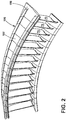
- Figure 2 illustrates a plurality of radially extending circumferentially spaced airfoils, or blades 70, with each blade 70 extending from a root 88 and terminating in a tip ( Figure 3 ) arranged in a circumferential row and supported by an arcuate inner band 96 and an arcuate outer band 98.
- the arcuate outer band 98 comprises a shroud assembly 100 made up of separate individual shroud elements 102, having opposing radial sides 107, 109, which together circumscribe the blades 70.
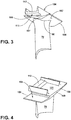
- Each shroud element 102 as depicted in Figures 3 and 4 is integrally formed with the blade 70 at the tip 90 and comprises a flange 104.
- the flange 104 includes a first and a second radial edge 106, 108 and a seat 110 that projects circumferentially beyond the first radial edge 106 illustrated in Figure 3 .
- the seat 110 is formed by the first radial edge 106 and the flange 104 in a portion 112 of the flange 104 that is circumferentially outboard of the first radial edge 106 illustrated in Figure 4 .
- FIG. 5 illustrates an airfoil assembly 114 in which the shroud element 102 is integrally formed with the blade 70 wherein the blade terminates in a dovetail 116.
- the dovetail 116 is formed to mount to the rotor 53.
- the blade 70 is sprung 118 to apply a preload to the interlocks.
- the blade 70 can be sprung as shown by solid line 118 from a predominantly parallel position 120 with respect to a neutral axis 122 of the airfoil assembly 114 to a bowed position 124 when interlocked.
- the blade 70 can also be sprung 118 from an initial position ofpredominantly bowed 126 to a parallel position 128 when interlocked.
- the final position 124, 128 will cause the second radial edge 108 bias outwardly and the seat to bias inwardly. This bias is caused by the compressive force Fc from the dovetail 116 which translates to an upward force F 2 at the second radial edge 108 and a downward force F 1 from the seat 110.
- Circumferentially adjacent shroud elements 102 interlock together forming a plurality of interlocks 130 between adjacent shroud elements 102 to form the shroud assembly 100 as illustrated in Figure 6 .
- a cross-sectional view of an exemplary embodiment of the shroud assembly 100 of Figure 6 is shown in Figure 7 where a first flange 132 having a first interlock element 134 mates with a second flange 136 having a second interlock element 138 where the first flange 132 overlies and abuts the second flange 136.
- the second radial edge 108 of the second flange 136 will bias toward the first flange 132 due to the forces F 1 and F 2 . This bias enables friction forces to form between the first and second interlock element surfaces that bond each shroud element 102 to the next radially adjacent shroud element 102.
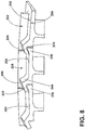
- FIG. 8 A second embodiment of the shroud assembly is contemplated in Figure 8 .
- the second embodiment is similar to the first embodiment, therefore, like parts will be identified with like numerals increasing by 100 respectively, with it being understood that the description of the like parts of the first embodiment applies to the additional embodiments, unless otherwise noted.
- a first interlock element 234 formed on a first flange 232 includes an angled seat 210 formed to receive an angled second interlock element 238 formed on a second flange 236.
- the flange 204 of each shroud element 202 therefore includes an angled seat 210 and an angled portion 240 formed to fit into the angled seat 210. While illustrated as two ramps 242, 244 forming an apex 246, the angled seat 210 and angled portion 240 can be any shape where the first interlock element 234 is formed to receive the second interlock element 238.
- a method of forming a shroud assembly comprising a shroud element integrally formed with a blade, about a plurality of rotating blades in a turbine engines includes forming an interlock between circumferentially adjacent tips of the blades and preloading the interlock. The preloading of the interlock where an interlock element is made to bias towards another interlock element.
- Prior art for shroud blade assemblies include Z-shaped interlocks.
- Implementing airfoil and shroud radial bending ensures contact between interlock elements to achieve outer band preload at operating conditions without typical torsional bending used in Z-shaped shroud design which requires a pre-twist.
- This type of bending also only requires blade balancing for centrifugal forces and improves damping at blade resonant vibrations due to increased contact areas between the interlock element surfaces. This increase in contact area also provides for a reduction in outer flowpath leakages.
- the simplified shape of design and removing a need for a pre-twist eases manufacturing.
Landscapes
- Engineering & Computer Science (AREA)
- Mechanical Engineering (AREA)
- General Engineering & Computer Science (AREA)
- Architecture (AREA)
- Structures Of Non-Positive Displacement Pumps (AREA)
- Turbine Rotor Nozzle Sealing (AREA)
Applications Claiming Priority (1)
| Application Number | Priority Date | Filing Date | Title |
|---|---|---|---|
| PL416301A PL416301A1 (pl) | 2016-02-29 | 2016-02-29 | Zespół bandaża silnika turbinowego |
Publications (1)
| Publication Number | Publication Date |
|---|---|
| EP3225794A1 true EP3225794A1 (de) | 2017-10-04 |
Family
ID=58094284
Family Applications (1)
| Application Number | Title | Priority Date | Filing Date |
|---|---|---|---|
| EP17156817.3A Withdrawn EP3225794A1 (de) | 2016-02-29 | 2017-02-20 | Turbinenmotormantelringbaugruppe |
Country Status (6)
| Country | Link |
|---|---|
| US (1) | US20170306768A1 (de) |
| EP (1) | EP3225794A1 (de) |
| JP (1) | JP2017198190A (de) |
| CN (1) | CN107131005A (de) |
| CA (1) | CA2958106A1 (de) |
| PL (1) | PL416301A1 (de) |
Families Citing this family (8)
| Publication number | Priority date | Publication date | Assignee | Title |
|---|---|---|---|---|
| US10738634B2 (en) | 2018-07-19 | 2020-08-11 | Raytheon Technologies Corporation | Contact coupled singlets |
| CN114174636B (zh) * | 2019-06-28 | 2024-08-23 | 西门子能源全球两合公司 | 燃气涡轮发动机中的出口引导叶瓣组件 |
| FR3098746B1 (fr) * | 2019-07-17 | 2021-07-30 | Safran Aircraft Engines | Outillage et procede de demontage et de deplacement d’un carter de turbine du type trv d’une turbomachine d’aeronef |
| US11208903B1 (en) | 2020-11-20 | 2021-12-28 | Solar Turbines Incorporated | Stiffness coupling and vibration damping for turbine blade shroud |
| US11655719B2 (en) * | 2021-04-16 | 2023-05-23 | General Electric Company | Airfoil assembly |
| JP2023119098A (ja) * | 2022-02-16 | 2023-08-28 | 三菱重工航空エンジン株式会社 | タービン |
| FR3137121B1 (fr) * | 2022-06-22 | 2024-06-21 | Safran Aircraft Engines | Ensemble aubagé à liaison inter-plateformes par élément roulant interposé |
| CN117869016B (zh) * | 2024-03-12 | 2024-05-17 | 中国航发四川燃气涡轮研究院 | 一种降低涡轮外环导热的冷却单元及其分析方法 |
Citations (6)
| Publication number | Priority date | Publication date | Assignee | Title |
|---|---|---|---|---|
| EP1939401A2 (de) * | 2006-12-19 | 2008-07-02 | General Electric Company | Verfahren und Vorrichtung zur Lastübertragung bei Rotoranordnungen |
| US20110027088A1 (en) * | 2009-07-31 | 2011-02-03 | General Electric Company | Rotor blades for turbine engines |
| EP2423438A2 (de) * | 2010-08-31 | 2012-02-29 | General Electric Company | Turbinenlaufschaufel mit Deckband, profilierter Plattform und Axialschwalbenschwanz |
| EP2551459A2 (de) * | 2011-07-28 | 2013-01-30 | General Electric Company | Abdeckkappe für das Spitzendeckband einer keramischen Schaufel |
| EP2612996A1 (de) * | 2012-01-04 | 2013-07-10 | General Electric Company | Vorrichtung und Verfahren zur Ausrichtung von Spitzendeckbänder |
| EP2666969A1 (de) * | 2012-05-21 | 2013-11-27 | Alstom Technology Ltd | Leitschaufelkranz-Konstruktion |
Family Cites Families (1)
| Publication number | Priority date | Publication date | Assignee | Title |
|---|---|---|---|---|
| US8684674B2 (en) * | 2010-10-29 | 2014-04-01 | General Electric Company | Anti-rotation shroud for turbine engines |
-
2016
- 2016-02-29 PL PL416301A patent/PL416301A1/pl unknown
-
2017
- 2017-02-16 JP JP2017026516A patent/JP2017198190A/ja active Pending
- 2017-02-16 CA CA2958106A patent/CA2958106A1/en not_active Abandoned
- 2017-02-20 EP EP17156817.3A patent/EP3225794A1/de not_active Withdrawn
- 2017-02-24 US US15/441,597 patent/US20170306768A1/en not_active Abandoned
- 2017-02-28 CN CN201710113770.0A patent/CN107131005A/zh active Pending
Patent Citations (6)
| Publication number | Priority date | Publication date | Assignee | Title |
|---|---|---|---|---|
| EP1939401A2 (de) * | 2006-12-19 | 2008-07-02 | General Electric Company | Verfahren und Vorrichtung zur Lastübertragung bei Rotoranordnungen |
| US20110027088A1 (en) * | 2009-07-31 | 2011-02-03 | General Electric Company | Rotor blades for turbine engines |
| EP2423438A2 (de) * | 2010-08-31 | 2012-02-29 | General Electric Company | Turbinenlaufschaufel mit Deckband, profilierter Plattform und Axialschwalbenschwanz |
| EP2551459A2 (de) * | 2011-07-28 | 2013-01-30 | General Electric Company | Abdeckkappe für das Spitzendeckband einer keramischen Schaufel |
| EP2612996A1 (de) * | 2012-01-04 | 2013-07-10 | General Electric Company | Vorrichtung und Verfahren zur Ausrichtung von Spitzendeckbänder |
| EP2666969A1 (de) * | 2012-05-21 | 2013-11-27 | Alstom Technology Ltd | Leitschaufelkranz-Konstruktion |
Non-Patent Citations (1)
| Title |
|---|
| OXFORD ENGLISH DICTIONARY: "interlock. OED Online. Oxford University Press", 1 January 1989 (1989-01-01), XP055395539, Retrieved from the Internet <URL:http://www.oed.com/oed2/00119234> [retrieved on 20170802] * |
Also Published As
| Publication number | Publication date |
|---|---|
| CA2958106A1 (en) | 2017-08-29 |
| CN107131005A (zh) | 2017-09-05 |
| US20170306768A1 (en) | 2017-10-26 |
| JP2017198190A (ja) | 2017-11-02 |
| PL416301A1 (pl) | 2017-09-11 |
Similar Documents
| Publication | Publication Date | Title |
|---|---|---|
| EP3225794A1 (de) | Turbinenmotormantelringbaugruppe | |
| US20180328187A1 (en) | Turbine engine with an airfoil and insert | |
| US7631484B2 (en) | High pressure ratio aft fan | |
| CN109209511B (zh) | 具有扇形流动表面的翼型件组件 | |
| EP2241721A2 (de) | Schaufelprofil mit Element gegen die Strömungsablösung, zugehöriges Gasturbinentriebwerk und Betriebsverfahren | |
| US20200011347A1 (en) | Gas turbine engine with vane having a cooling inlet | |
| US10815789B2 (en) | Impingement holes for a turbine engine component | |
| US10648362B2 (en) | Spline for a turbine engine | |
| EP3075968A1 (de) | Turbinenrahmen und verkleidung für einen turbinenrahmen | |
| US10655495B2 (en) | Spline for a turbine engine | |
| EP2984290B1 (de) | Integral mit laufschaufeln versehener rotor | |
| US20180340437A1 (en) | Spline for a turbine engine | |
| US20180355741A1 (en) | Spline for a turbine engine | |
| US20180355754A1 (en) | Spline for a turbine engine | |
| EP3056685A1 (de) | Statorschaufel mit plattform mit schräger fläche | |
| EP3190261A1 (de) | Statorkranzstruktur für einen gasturbinenmotor | |
| JP2017110642A (ja) | ガスタービンエンジンの間隙の制御のコンプライアントなシュラウド | |
| CN112211680B (zh) | 带有密封件的涡轮发动机 | |
| CN107091122B (zh) | 具有冷却的涡轮发动机翼型件 | |
| US20180231026A1 (en) | Turbine engine compressor with a cooling circuit | |
| US10836499B2 (en) | Turbine engine with single wall cantilevered architecture | |
| US20210381389A1 (en) | Turbine engine component with a set of deflectors | |
| EP3000966A1 (de) | Verfahren und anordnung zur verminderung sekundärer wärme in einem gasturbinenmotor | |
| US10774661B2 (en) | Shroud for a turbine engine | |
| US11401835B2 (en) | Turbine center frame |
Legal Events
| Date | Code | Title | Description |
|---|---|---|---|
| PUAI | Public reference made under article 153(3) epc to a published international application that has entered the european phase |
Free format text: ORIGINAL CODE: 0009012 |
|
| AK | Designated contracting states |
Kind code of ref document: A1 Designated state(s): AL AT BE BG CH CY CZ DE DK EE ES FI FR GB GR HR HU IE IS IT LI LT LU LV MC MK MT NL NO PL PT RO RS SE SI SK SM TR |
|
| AX | Request for extension of the european patent |
Extension state: BA ME |
|
| STAA | Information on the status of an ep patent application or granted ep patent |
Free format text: STATUS: THE APPLICATION IS DEEMED TO BE WITHDRAWN |
|
| 18D | Application deemed to be withdrawn |
Effective date: 20180405 |