EP2612795A1 - Wireless communications circuit - Google Patents
Wireless communications circuit Download PDFInfo
- Publication number
- EP2612795A1 EP2612795A1 EP20130150043 EP13150043A EP2612795A1 EP 2612795 A1 EP2612795 A1 EP 2612795A1 EP 20130150043 EP20130150043 EP 20130150043 EP 13150043 A EP13150043 A EP 13150043A EP 2612795 A1 EP2612795 A1 EP 2612795A1
- Authority
- EP
- European Patent Office
- Prior art keywords
- motion
- base station
- circuit
- communication circuit
- response
- Prior art date
- Legal status (The legal status is an assumption and is not a legal conclusion. Google has not performed a legal analysis and makes no representation as to the accuracy of the status listed.)
- Granted
Links
- 238000004891 communication Methods 0.000 title claims abstract description 171
- 230000033001 locomotion Effects 0.000 claims abstract description 103
- 230000004044 response Effects 0.000 claims abstract description 54
- 238000000034 method Methods 0.000 claims description 9
- 238000012545 processing Methods 0.000 claims description 2
- 230000003595 spectral effect Effects 0.000 claims 2
- 238000013459 approach Methods 0.000 description 17
- 238000010586 diagram Methods 0.000 description 9
- 230000001133 acceleration Effects 0.000 description 5
- 238000012986 modification Methods 0.000 description 4
- 230000004048 modification Effects 0.000 description 4
- 230000003213 activating effect Effects 0.000 description 3
- 230000004913 activation Effects 0.000 description 3
- 238000001514 detection method Methods 0.000 description 3
- 230000005540 biological transmission Effects 0.000 description 2
- 230000000694 effects Effects 0.000 description 2
- 230000008569 process Effects 0.000 description 2
- 230000035939 shock Effects 0.000 description 2
- 230000002457 bidirectional effect Effects 0.000 description 1
- 230000008859 change Effects 0.000 description 1
- 238000013461 design Methods 0.000 description 1
- 230000005520 electrodynamics Effects 0.000 description 1
- 230000005284 excitation Effects 0.000 description 1
- 230000007246 mechanism Effects 0.000 description 1
- 238000010295 mobile communication Methods 0.000 description 1
- 238000012544 monitoring process Methods 0.000 description 1
- 230000000737 periodic effect Effects 0.000 description 1
- 230000037081 physical activity Effects 0.000 description 1
- 238000012552 review Methods 0.000 description 1
- 238000010183 spectrum analysis Methods 0.000 description 1
- 230000001052 transient effect Effects 0.000 description 1
- 238000012795 verification Methods 0.000 description 1
Images

Classifications
-
- G—PHYSICS
- G07—CHECKING-DEVICES
- G07C—TIME OR ATTENDANCE REGISTERS; REGISTERING OR INDICATING THE WORKING OF MACHINES; GENERATING RANDOM NUMBERS; VOTING OR LOTTERY APPARATUS; ARRANGEMENTS, SYSTEMS OR APPARATUS FOR CHECKING NOT PROVIDED FOR ELSEWHERE
- G07C9/00—Individual registration on entry or exit
- G07C9/00174—Electronically operated locks; Circuits therefor; Nonmechanical keys therefor, e.g. passive or active electrical keys or other data carriers without mechanical keys
- G07C9/00309—Electronically operated locks; Circuits therefor; Nonmechanical keys therefor, e.g. passive or active electrical keys or other data carriers without mechanical keys operated with bidirectional data transmission between data carrier and locks
-
- B—PERFORMING OPERATIONS; TRANSPORTING
- B60—VEHICLES IN GENERAL
- B60R—VEHICLES, VEHICLE FITTINGS, OR VEHICLE PARTS, NOT OTHERWISE PROVIDED FOR
- B60R25/00—Fittings or systems for preventing or indicating unauthorised use or theft of vehicles
- B60R25/20—Means to switch the anti-theft system on or off
- B60R25/24—Means to switch the anti-theft system on or off using electronic identifiers containing a code not memorised by the user
-
- G—PHYSICS
- G07—CHECKING-DEVICES
- G07C—TIME OR ATTENDANCE REGISTERS; REGISTERING OR INDICATING THE WORKING OF MACHINES; GENERATING RANDOM NUMBERS; VOTING OR LOTTERY APPARATUS; ARRANGEMENTS, SYSTEMS OR APPARATUS FOR CHECKING NOT PROVIDED FOR ELSEWHERE
- G07C9/00—Individual registration on entry or exit
- G07C9/00174—Electronically operated locks; Circuits therefor; Nonmechanical keys therefor, e.g. passive or active electrical keys or other data carriers without mechanical keys
- G07C9/00309—Electronically operated locks; Circuits therefor; Nonmechanical keys therefor, e.g. passive or active electrical keys or other data carriers without mechanical keys operated with bidirectional data transmission between data carrier and locks
- G07C2009/00365—Electronically operated locks; Circuits therefor; Nonmechanical keys therefor, e.g. passive or active electrical keys or other data carriers without mechanical keys operated with bidirectional data transmission between data carrier and locks in combination with a wake-up circuit
- G07C2009/0038—Electronically operated locks; Circuits therefor; Nonmechanical keys therefor, e.g. passive or active electrical keys or other data carriers without mechanical keys operated with bidirectional data transmission between data carrier and locks in combination with a wake-up circuit whereby the wake-up circuit is situated in the keyless data carrier
-
- G—PHYSICS
- G07—CHECKING-DEVICES
- G07C—TIME OR ATTENDANCE REGISTERS; REGISTERING OR INDICATING THE WORKING OF MACHINES; GENERATING RANDOM NUMBERS; VOTING OR LOTTERY APPARATUS; ARRANGEMENTS, SYSTEMS OR APPARATUS FOR CHECKING NOT PROVIDED FOR ELSEWHERE
- G07C9/00—Individual registration on entry or exit
- G07C9/00174—Electronically operated locks; Circuits therefor; Nonmechanical keys therefor, e.g. passive or active electrical keys or other data carriers without mechanical keys
- G07C2009/00579—Power supply for the keyless data carrier
- G07C2009/00587—Power supply for the keyless data carrier by battery
-
- G—PHYSICS
- G07—CHECKING-DEVICES
- G07C—TIME OR ATTENDANCE REGISTERS; REGISTERING OR INDICATING THE WORKING OF MACHINES; GENERATING RANDOM NUMBERS; VOTING OR LOTTERY APPARATUS; ARRANGEMENTS, SYSTEMS OR APPARATUS FOR CHECKING NOT PROVIDED FOR ELSEWHERE
- G07C9/00—Individual registration on entry or exit
- G07C9/00174—Electronically operated locks; Circuits therefor; Nonmechanical keys therefor, e.g. passive or active electrical keys or other data carriers without mechanical keys
- G07C2009/00753—Electronically operated locks; Circuits therefor; Nonmechanical keys therefor, e.g. passive or active electrical keys or other data carriers without mechanical keys operated by active electrical keys
- G07C2009/00769—Electronically operated locks; Circuits therefor; Nonmechanical keys therefor, e.g. passive or active electrical keys or other data carriers without mechanical keys operated by active electrical keys with data transmission performed by wireless means
- G07C2009/00793—Electronically operated locks; Circuits therefor; Nonmechanical keys therefor, e.g. passive or active electrical keys or other data carriers without mechanical keys operated by active electrical keys with data transmission performed by wireless means by Hertzian waves
-
- G—PHYSICS
- G07—CHECKING-DEVICES
- G07C—TIME OR ATTENDANCE REGISTERS; REGISTERING OR INDICATING THE WORKING OF MACHINES; GENERATING RANDOM NUMBERS; VOTING OR LOTTERY APPARATUS; ARRANGEMENTS, SYSTEMS OR APPARATUS FOR CHECKING NOT PROVIDED FOR ELSEWHERE
- G07C9/00—Individual registration on entry or exit
- G07C9/00174—Electronically operated locks; Circuits therefor; Nonmechanical keys therefor, e.g. passive or active electrical keys or other data carriers without mechanical keys
- G07C9/00944—Details of construction or manufacture
- G07C2009/0096—Electronic keys comprising a non-biometric sensor
Definitions
- transponders and base stations communicate with one another to effect a variety of communications.
- transponders can be used in automotive applications for passive keyless entry (PKE) for activating an unlocking mechanism to unlock the doors of a vehicle, or passive keyless go (PKG) for activating an ignition-type circuit for starting an engine or otherwise activating a drive system in a vehicle.
- PKE passive keyless entry
- PKG passive keyless go
- the transponders communicate with base stations that are located in the vehicle, and the base stations communicate with other circuits in the vehicle to carry out the aforesaid functions.
- the communications between the transponder and base station can be unidirectional or bidirectional, depending on the protocol.
- circuits that require significant power may be unusable in a variety of applications, such as those involving the use of battery power, due to high power requirements.
- many systems require certain circuits to be actively powered in order to operate as a passive access circuit, such as for responding to a polling signal generated at a regular interval, in order to establish base station-transponder communications. This can require sub-threshold circuit operation, and limit the complexity and function of circuit configurations therein.
- Various example embodiments are directed to wireless communications, and to addressing various challenges including those discussed above.
- an apparatus includes a portable motion-sensing circuit and a communication circuit communicatively coupled to the motion-sensing circuit.
- the motion-sensing circuit configured and arranged to be carried by a user and indicates that motion is sensed in response to detecting user movement (e.g. , whether the user has been moving for a predetermined period of time).
- the communication circuit operates in an active mode in response to the motion being sensed at the motion-sensing circuit, and an inactive mode in which the communication circuit is consuming less power relative to power consumed by the communication circuit in the active mode. In the active mode, access authentication communications are permitted with the communication circuit, and access authentication communications with the communication circuit are inhibited in the inactive mode.
- the base station operates in an active mode and in an inactive mode in which the base station inhibits authentication communications and consumes less power relative to power consumed by the base station in the active mode.
- the transponder circuit can be carried by a user, and includes a communication circuit and a motion-sensing circuit that senses motion indicative of movement of the user.
- the communication circuit communicates wirelessly with the base station in response to the sensed motion to provide a wake-up signal to the base station, with the base station being responsive to the wake-up signal by operating in the active mode.
- the communication circuit also communicates wirelessly with the base station to provide an access authentication communication to the base station for authenticating the remote transponder.
- Another example embodiment is directed to a method for communicating.
- a portable motion-sensing device an indication that motion is sensed is provided in response to detecting whether a user has been moving for a predetermined period of time.
- a wireless communication circuit is operated in an active mode in which access authentication communications with the communication circuit are permitted.
- the communication circuit is operated in an inactive mode. in which the communication circuit is consuming less power relative to power consumed by the communication circuit in the active mode, and in which access authentication communications with the communication circuit are inhibited.
- the inactive mode may be effected, for example, after a period of non-motion, non-walking motion, or prior to operating in the active mode.
- the present invention is believed to be applicable to a variety of different types of circuits, devices and systems for and/or involving wireless communications and/or security-based access. While the present invention is not necessarily limited in this context, various aspects of the invention may be appreciated through a discussion of related examples.
- an apparatus/method involves a portable motion-sensing circuit, which can be carried by a user, and which indicates that motion is sensed in response to detecting whether the user has been moving ( e.g. , for a predetermined period of time).
- a communication circuit operates in an active mode and an inactive mode, and consumes less power in the in active mode relative to power consumed in the active mode.
- the communication circuit operates in the active mode based upon the motion sensed at the motion-sensing circuit and permits access authentication communications in the active mode. In the inactive mode, the communication circuit inhibits such access authentication communications.
- the communication circuit is co-located with the portable motion-sensing circuit and communicatively coupled to the motion-sensing circuit via a wired link (e.g ., the circuits may be located on a common integrated circuit).
- the communication circuit is remote from the portable motion-sensing circuit and communicatively coupled to the motion-sensing circuit via a wireless communication channel.
- the communications circuit includes a first circuit co-located with the motion sensing circuit, and a second remote circuit that is connected with the first circuit via a wireless communication link.
- a controller is connected to the communication circuit and operates to, in the inactive mode, control the communication circuit in a low-power state in which wireless access authentication communications with a remote transponder are inhibited, and in the active mode, control the communication circuit in a high-power state in which the access authentication communications are facilitated.
- the communication circuit includes a low-frequency communication circuit and a high-frequency communication circuit.
- the communication circuit enters the active mode by powering the high-frequency communication circuit to send a wake-up signal to activate a circuit in a remote base station, in response to motion detected at the motion-sensing circuit.
- the communication circuit further communicates wirelessly between a base station and a remote transponder by using the low-frequency circuit to detect a response from the base station to the wake-up signal, identify the base station based upon the detected response, and communicate access authentication communication to the base station based on the identification.
- the communication circuit includes a low-frequency communication circuit and enters the active mode by powering the low-frequency communication circuit in response to motion detected at the motion-sensing circuit, and by using the low-frequency communication circuit to detect a polling signal from a remote base station.
- the remote base station is identified based upon the polling signal, and an access authentication communication is communicated to the base station based on the identification.
- the communication circuit enters the inactive mode in response to a motion condition indicating a lack of motion for a predefined time period, and a state of communications between the communication circuit and a remote base station.
- the state of communications may involve the passing of an active entry sequence in which an authentication communication is transmitted from a remote transponder to a base station, or after a successful vehicle drive activation sequence ( e.g. , starting an automobile).
- Another example embodiment is directed to a communications apparatus having a base station and a transponder.
- the base station operates in an active mode and in an inactive mode in which the base station inhibits authentication communications and consumes less power, relative to power consumed by the base station in the active mode.
- the transponder can be carried by a user and includes a communication circuit and a motion-sensing circuit that senses motion indicative of movement of the user.
- the communication circuit communicates wirelessly with the base station to provide a wake-up signal to the base station in response to the sensed motion, and to provide an access authentication communication to the base station for authenticating the remote transponder.
- the base station is responsive to the wake-up signal by operating in the active mode.
- the base station includes a high-frequency communication circuit and that operates in the inactive mode by polling for a high-frequency signal from the transponder.
- the transponder communicates a high-frequency wake-up signal to the base station in response to the sensed motion, and the base station responds to the wake-up signal by powering a low-frequency communication circuit and communicating authentication communications with the transponder via the low-frequency circuit, for authenticating the transponder to the base station.
- the base station further provides user access to a vehicle in response to authenticating the transponder, such as by unlocking the vehicle for user access, or permitting engagement of a drive system.
- Figure 1 shows communications circuits arranged in a communications system 100, in accordance with one or more example embodiments.
- the circuits shown in Figure 1 may be implemented individually or as a system, for wireless communications.
- the circuits may be implemented for a passive keyless entry (PKE) application to control access to a vehicle, or a passive keyless go (PKG) application to control the activation of a drive system (e.g. , by permitting ignition access to start an engine, or permitting the activation of a drive system for a battery-powered vehicle).
- PKE passive keyless entry
- PKG passive keyless go
- a first communication circuit 110 includes a base station circuit 112, a control unit 114 and a UHF circuit 116.
- a second remote/mobile communication circuit 120 includes a transponder 122, a microcontroller 124, a UHF transmitter 126 and a motion sensor 128, with at least the transponder and microcontroller optionally included in a common circuit 121.
- the first communication circuit 110 which is shown by way of example as implemented in a vehicle 130, emits a low frequency alternating magnetic field carrying some data content.
- the second circuit 120 which is shown by way of example as implemented in a key 140, detects this field from some distance from the first communication circuit 110.
- the motion sensor 128 is configured to generate an output based upon motion of the second circuit 120 (e.g ., movement of the key 140).
- the second circuit 120 is responsive to the motion by entering an active mode, in which the microcontroller 124 controls the second communication circuit to operate in an active mode. In the active mode, the second circuit 120 operates for communicating signals with the first circuit 110, such as by operating the transmitter in a polling mode to communicate a polling signal to initiate communications with the first circuit 110.
- the second circuit 120 receives a communication from the first circuit 110 when in the active mode, the second circuit generates and communicates an access signal, via the transmitter 126, to the first circuit for unlocking a door or doors in the vehicle 130.
- the circuits shown in Figure 1 may be operated in a variety of manners.
- the motion sensor 128 senses motion, it provides a signal to the microcontroller 124, which operates to wake up the second circuit 120 for receiving data.
- the transponder 122 operates to receive a polling-type signal generated by the base station circuit 112, and sends a UHF signal via the UHF transmitter 126 in response.
- the control unit 114 operates in response to the signal received at the UHF circuit 116, to facilitate access to the vehicle 130.
- the control unit 114 may decrypt or otherwise verify that the UHF response received from the UHF transmitter 126 is authentic.
- This approach may involve additional communications, such as an acknowledge communication from the second circuit 120, in response to which the first circuit 110 sends another communication to initiate verification.
- the communications may be effected via one or both of high frequency or low frequency links, and may involve use of the UHF circuit 116 as a transmitter.
- the first circuit 110 powers the second circuit 120 via an RF signal that is transmitted from the base station circuit 112 to the transponder 122.
- the transponder 122 receives wireless power via the radio frequency signal generated by the base station circuit 112.
- the second communication circuit 120 uses the wireless power to operate the microcontroller 124 and UHF transmitter 126, to communicate with the first circuit 110 via UHF circuit 116.
- the second circuit 120 operates in a low power mode for initializing communications with the first circuit 110, based upon a motion-based characteristic of the motion sensor 128.
- the second circuit 120 may switch to an active mode for initializing communications in response to an output indicating that motion has been detected (and to remain in the active mode for a predetermined time), or operate in an inactive mode after such a predetermined time and/or in the absence of motion.
- an inactive mode virtually all the circuitry in the second circuit 120 can be shut down, while maintaining circuitry that can be used to wake-up the circuit (e.g ., gating to awaken the circuit from sleep mode, start the clock generation and activate low-frequency detection at the transponder 122).
- the second circuit 120 is maintained in an inactive mode based upon an output from the motion sensor. During this inactive mode, the second circuit 120 operates in a manner that is unresponsive to polling-type signals, such as those received from the first circuit 110, to save power and further to mitigate undesirable communications. While in the inactive mode, the second circuit 120 is unresponsive to signals corresponding to those from a base station type circuit 112 as shown in first circuit 110, such as those that may be received via a relay-type of circuit under an attack in which a signal from the base station circuit is mimicked or relayed to obtain unauthorized access to the vehicle 130.
- the microcontroller 124 is configured to control the mode of the second circuit 120, based upon conditions that are in addition to and/or as an alternative to a condition of the motion sensor 128.
- the microcontroller carries out spectral analysis of a signal corresponding to the motion detected at the motion sensor 128, to determine a type of motion. This approach can be used, for example, to differentiate between walking motion (e.g ., in which the second circuit 120 is desirably activated) and vibration or a single bump.
- the microcontroller 124 may also operate to inhibit the motion sensor 128 in certain embodiments, such as when the second circuit 120 is in a car and a valid access sequence has been carried out at the second circuit as discussed above, but the car is stationary in traffic for an extended period of time.
- the sleep mode is disabled so that the second circuit 120 is operable without requiring any subsequent motion-based wake-up, once in an active mode.
- the second circuit 120 operates in a mode that is set based upon a signal from the first circuit, such as a circuit indicative of the vehicle 130 successively entering an operational state (e.g ., an engine has been started or otherwise enabled).
- the second circuit 120 operates to initiate communications with the first circuit, such as by using the UHF circuit 116.
- the motion sensor 128 places the second circuit 120 in an active mode, in which the UHF circuit 116 generates a signal ( e.g ., in response to the motion sensor 128 detecting a walking motion).
- the first circuit 110 responds to the generated signal by carrying out communications to facilitate access to the vehicle 130.
- the base station circuit 112 can remain dormant ( e.g ., in a non-communicative mode) until a motion-initiated signal is generated by the second circuit 120. By maintaining the base station circuit 112 in a dormant state, power can be saved in the car, limiting the amount of time that the base station circuit needs to be activated.
- a variety of different types of motion sensors and corresponding circuitry can be used in connection with the various embodiments as discussed herein, such as with the motion sensor circuit 128 shown in and described in connection with Figure 1 .
- sensors that detect acceleration or a change in a local DC magnetic field direction can be used to activate the second circuit.
- Piezoelectric acceleration sensors such as those used in acoustic instrumentation, can be used to generate voltage directly, which can be connected to other circuitry in the second circuit 120 ( e.g., as part of a CMOS based key electronic system having a high impedance suitable for connection to such a sensor).
- the sensor operation can also be limited, such as may be relevant to a polling-type approach, in which the sensor is powered for sensing motion on a limited basis.
- a self powered sensor is used, such as a sensor having an electrodynamic circuit including a moving magnet that induces an EMF in a coil to power the sensor for generating a motion-based wake-up signal to other circuitry.
- There inputs will, of course, need to have voltage limiting circuits to prevent damage in the event of a large transient signal due to the key suffering a large mechanical shock.
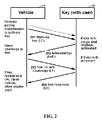
- a signal diagram 200 shows a communications approach for communicating between base and transponder circuits, respectively at a vehicle base station 210 and a key fob-type device 220, in accordance with another example embodiment of the present invention.
- periodic polling transmissions 201 such as low-frequency wake-up communications, are generated and used to activate a key such as the key fob-type device 220.
- the key device 220 is in range of the polling transmissions 201 and is also motion-activated ( e.g ., as discussed herein), the key device generates an acknowledge signal 202, such as a UHF signal.
- the base station 210 responds to the acknowledge signal by issuing a challenge to the key device 220, via a communication 203 (e.g., low frequency) including vehicle identification data for the base station, and challenge data. If the vehicle identification data is correct (e.g., matches data stored at the key device 220), the key device 220 processes the challenge date (e.g., security data) and returns a key response 204 ( e.g., low frequency). The base station 210 uses the key response 204 to activate a circuit or otherwise grant access to a vehicle, such as by unlocking a door or enabling an engine/drive system.
- a communication 203 e.g., low frequency
- the key device 220 processes the challenge date (e.g., security data) and returns a key response 204 (e.g., low frequency).
- the base station 210 uses the key response 204 to activate a circuit or otherwise grant access to a vehicle, such as by unlocking a door or enabling an engine/drive system.
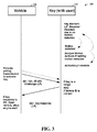
- FIG. 3 shows another signal diagram 300 for communicating between base and transponder circuits 310 and 320, in accordance with another example embodiment of the present invention.
- the transponder 320 includes a motion sensor and operates in a dormant, or low-power mode, when motion is not sensed. If motion is detected, the transponder 320 analyzes the motion to determine whether the motion type satisfies criteria, such as motion information pertaining to a user walking. If the motion analysis satisfies criteria, the transponder activates, such as by powering a low-frequency transceiver.
- the base circuit 310 generates a polling signal 301 including vehicle identification data and challenge data, and transmits the signal ( e.g., via low frequency). If the transponder circuit 320 is in the active state and within range of the poling signal 301, the transponder sends a response 302 ( e.g., low frequency) that is processed by the base circuit 310 and authenticated to grant access to a vehicle.
- a polling signal 301 including vehicle identification data and challenge data
- the transponder sends a response 302 (e.g., low frequency) that is processed by the base circuit 310 and authenticated to grant access to a vehicle.
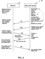
- Figure 4 shows another signal diagram 400 for communicating between a base station 410 and a transponder 420, in accordance with another example embodiment of the present invention.
- the transponder 420 remains in a dormant state when no motion is detected, and in response to detected motion, analyzes the motion to determine whether the motion meets a certain criteria. If the motion meets the criteria, the transponder 420 enters an active state and sends UHF communication 401 and 402 (upon continued detected motion).
- the base station 410 polls for UHF communications, such as for remote keyless entry (RKE) and/or passive keyless entry (PKE) sequences. If the base station 410 detects the UHF communication (e.g., 401 or 402), it sends a low-frequency communication 403 including vehicle identification data and challenge data. The transponder 420 processes the low-frequency communication 403 and, if the vehicle ID is correct, generates a response to the challenge data and sends the response 404 to the base station 410. In turn, the base station grants access based on the response 404.
- RKE remote keyless entry
- PKE passive keyless entry
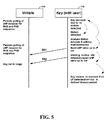
- Figure 5 shows another signal diagram 500 for communicating between a base station 510 and transponder 520, in accordance with another example embodiment of the present invention.
- the signal diagram 500 may, for example, be implemented with the approach shown in Figure 4 , but in response to failing to detect a return signal from a base station and after a timeout period with respect to motion.
- the transponder 520 remains in a dormant state when no motion is detected, and in response to detected motion, analyzes the motion to determine whether the motion meets a certain criteria. If the motion meets the criteria, the transponder 520 enters an active state and sends UHF communication 501 and 502 (upon continued detected motion). If no motion is detected and if no response is received from the base station 510, the transponder 520 enters a timeout mode. If the timeout mode lapses before receiving a response from the base station 510, the transponder 520 returns to the dormant state.
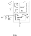
- FIG. 6 shows one such device, in a transponder 600, in accordance with another example embodiment of the present invention.
- the transponder 600 may, for example, be implemented with the transponders shown in and/or described in connection with Figures 1-6 .
- the transponder 600 includes a security function and key control circuit 610, which is coupled to an LF receiver 620 and a UHF transmitter 630, respectively coupled to an LF antenna 622 and a UHF antenna 632. Via the LF receiver 620, the control circuit 610 receives low frequency communications from a base station. The control circuit 610 similarly transmits high frequency communications to the base station via the UHF transmitter 630.
- the transponder 600 also includes switching circuitry 640 and 642, which is responsive to an acceleration signal detection/analysis circuit 650 and the processing of motion-based signals thereat. More specifically, the switching circuitry 640 and 642 functions to couple power to circuits in the transponder 600, as may be controlled by the control circuit 610 ( e.g., to inhibit motion sensing).
- the transponder 600 also includes motion-sensing circuits, including an acceleration sensor 660 and an over-voltage circuit 670 (e.g., a shock excitation limiter circuit). An output from these circuits is processed at the acceleration signal detection/analysis circuit 650, for determining the presence of motion and, if appropriate, analyzing the type of motion.
- motion-sensing circuits including an acceleration sensor 660 and an over-voltage circuit 670 (e.g., a shock excitation limiter circuit).
- An output from these circuits is processed at the acceleration signal detection/analysis circuit 650, for determining the presence of motion and, if appropriate, analyzing the type of motion.
Abstract
Description
- In many wireless communications systems, transponders and base stations communicate with one another to effect a variety of communications. For example, transponders can be used in automotive applications for passive keyless entry (PKE) for activating an unlocking mechanism to unlock the doors of a vehicle, or passive keyless go (PKG) for activating an ignition-type circuit for starting an engine or otherwise activating a drive system in a vehicle. Generally, the transponders communicate with base stations that are located in the vehicle, and the base stations communicate with other circuits in the vehicle to carry out the aforesaid functions. The communications between the transponder and base station can be unidirectional or bidirectional, depending on the protocol.
- Unfortunately, such communications systems may be limited in their application and function due to power use constraints. Moreover, circuits that require significant power may be unusable in a variety of applications, such as those involving the use of battery power, due to high power requirements. For example, many systems require certain circuits to be actively powered in order to operate as a passive access circuit, such as for responding to a polling signal generated at a regular interval, in order to establish base station-transponder communications. This can require sub-threshold circuit operation, and limit the complexity and function of circuit configurations therein. These and other matters have presented challenges to the design and implementation of communications systems for a variety of applications.
- Various example embodiments are directed to wireless communications, and to addressing various challenges including those discussed above.
- According to an example embodiment, an apparatus includes a portable motion-sensing circuit and a communication circuit communicatively coupled to the motion-sensing circuit. The motion-sensing circuit configured and arranged to be carried by a user and indicates that motion is sensed in response to detecting user movement (e.g., whether the user has been moving for a predetermined period of time). The communication circuit operates in an active mode in response to the motion being sensed at the motion-sensing circuit, and an inactive mode in which the communication circuit is consuming less power relative to power consumed by the communication circuit in the active mode. In the active mode, access authentication communications are permitted with the communication circuit, and access authentication communications with the communication circuit are inhibited in the inactive mode.
- Another example embodiment is directed to a communications apparatus including a base station and a transponder circuit. The base station operates in an active mode and in an inactive mode in which the base station inhibits authentication communications and consumes less power relative to power consumed by the base station in the active mode. The transponder circuit can be carried by a user, and includes a communication circuit and a motion-sensing circuit that senses motion indicative of movement of the user. The communication circuit communicates wirelessly with the base station in response to the sensed motion to provide a wake-up signal to the base station, with the base station being responsive to the wake-up signal by operating in the active mode. The communication circuit also communicates wirelessly with the base station to provide an access authentication communication to the base station for authenticating the remote transponder.
- Another example embodiment is directed to a method for communicating. In a portable motion-sensing device, an indication that motion is sensed is provided in response to detecting whether a user has been moving for a predetermined period of time. In response to the sensed motion, a wireless communication circuit is operated in an active mode in which access authentication communications with the communication circuit are permitted. The communication circuit is operated in an inactive mode. in which the communication circuit is consuming less power relative to power consumed by the communication circuit in the active mode, and in which access authentication communications with the communication circuit are inhibited. The inactive mode may be effected, for example, after a period of non-motion, non-walking motion, or prior to operating in the active mode.
- The above discussion is not intended to describe each embodiment or every implementation of the present disclosure. The figures and following description also exemplify various embodiments.
- Various example embodiments may be more completely understood in consideration of the following detailed description in connection with the accompanying drawings, in which:
-
Figure 1 shows communications circuits and a communications system, in accordance with one or more example embodiments of the present invention; -
Figure 2 is a signal diagram showing a communications approach for communicating between base and transponder circuits, in accordance with another example embodiment of the present invention; -
Figure 3 is a signal diagram showing a communications approach for communicating between base and transponder circuits, in accordance with another example embodiment of the present invention; -
Figure 4 is a signal diagram showing a communications approach for communicating between base and transponder circuits, in accordance with another example embodiment of the present invention; -
Figure 5 is a signal diagram showing a communications approach for communicating between base and transponder circuits, in accordance with another example embodiment of the present invention; and -
Figure 6 is a transponder circuit, in accordance with another example embodiment of the present invention. - While the invention is amenable to various modifications and alternative forms, specifics thereof have been shown by way of example in the drawings and will be described in detail. It should be understood, however, that the intention is not to limit the invention to the particular embodiments described. On the contrary, the intention is to cover all modifications, equivalents, and alternatives falling within the scope of the invention including aspects defined in the claims.
- The present invention is believed to be applicable to a variety of different types of circuits, devices and systems for and/or involving wireless communications and/or security-based access. While the present invention is not necessarily limited in this context, various aspects of the invention may be appreciated through a discussion of related examples.
- In accordance with various example embodiments, an apparatus/method involves a portable motion-sensing circuit, which can be carried by a user, and which indicates that motion is sensed in response to detecting whether the user has been moving (e.g., for a predetermined period of time). A communication circuit operates in an active mode and an inactive mode, and consumes less power in the in active mode relative to power consumed in the active mode. The communication circuit operates in the active mode based upon the motion sensed at the motion-sensing circuit and permits access authentication communications in the active mode. In the inactive mode, the communication circuit inhibits such access authentication communications. In some implementations, the communication circuit is co-located with the portable motion-sensing circuit and communicatively coupled to the motion-sensing circuit via a wired link (e.g., the circuits may be located on a common integrated circuit). In other implementations, the communication circuit is remote from the portable motion-sensing circuit and communicatively coupled to the motion-sensing circuit via a wireless communication channel. In still other implementations, the communications circuit includes a first circuit co-located with the motion sensing circuit, and a second remote circuit that is connected with the first circuit via a wireless communication link.
- In another example embodiment, a controller is connected to the communication circuit and operates to, in the inactive mode, control the communication circuit in a low-power state in which wireless access authentication communications with a remote transponder are inhibited, and in the active mode, control the communication circuit in a high-power state in which the access authentication communications are facilitated.
- In some implementations, the communication circuit includes a low-frequency communication circuit and a high-frequency communication circuit. The communication circuit enters the active mode by powering the high-frequency communication circuit to send a wake-up signal to activate a circuit in a remote base station, in response to motion detected at the motion-sensing circuit. The communication circuit further communicates wirelessly between a base station and a remote transponder by using the low-frequency circuit to detect a response from the base station to the wake-up signal, identify the base station based upon the detected response, and communicate access authentication communication to the base station based on the identification.
- In certain embodiments in which the communication circuit is integrated with the portable motion-sensing circuit, the communication circuit includes a low-frequency communication circuit and enters the active mode by powering the low-frequency communication circuit in response to motion detected at the motion-sensing circuit, and by using the low-frequency communication circuit to detect a polling signal from a remote base station. The remote base station is identified based upon the polling signal, and an access authentication communication is communicated to the base station based on the identification.
- In some implementations, the communication circuit enters the inactive mode in response to a motion condition indicating a lack of motion for a predefined time period, and a state of communications between the communication circuit and a remote base station. For example, the state of communications may involve the passing of an active entry sequence in which an authentication communication is transmitted from a remote transponder to a base station, or after a successful vehicle drive activation sequence (e.g., starting an automobile).
- Another example embodiment is directed to a communications apparatus having a base station and a transponder. The base station operates in an active mode and in an inactive mode in which the base station inhibits authentication communications and consumes less power, relative to power consumed by the base station in the active mode. The transponder can be carried by a user and includes a communication circuit and a motion-sensing circuit that senses motion indicative of movement of the user. The communication circuit communicates wirelessly with the base station to provide a wake-up signal to the base station in response to the sensed motion, and to provide an access authentication communication to the base station for authenticating the remote transponder. The base station is responsive to the wake-up signal by operating in the active mode.
- In some implementations, the base station includes a high-frequency communication circuit and that operates in the inactive mode by polling for a high-frequency signal from the transponder. The transponder communicates a high-frequency wake-up signal to the base station in response to the sensed motion, and the base station responds to the wake-up signal by powering a low-frequency communication circuit and communicating authentication communications with the transponder via the low-frequency circuit, for authenticating the transponder to the base station. In some implementations, the base station further provides user access to a vehicle in response to authenticating the transponder, such as by unlocking the vehicle for user access, or permitting engagement of a drive system.
- Turning now to the Figures,
Figure 1 shows communications circuits arranged in acommunications system 100, in accordance with one or more example embodiments. The circuits shown inFigure 1 may be implemented individually or as a system, for wireless communications. For example, the circuits may be implemented for a passive keyless entry (PKE) application to control access to a vehicle, or a passive keyless go (PKG) application to control the activation of a drive system (e.g., by permitting ignition access to start an engine, or permitting the activation of a drive system for a battery-powered vehicle). By way of example, aspects ofFigure 1 and the following description are made in the context of a PKE application, with the understanding that the circuits and/or system may be employed for PKG, a combination of PKE and PKG, or other approaches (e.g., for secure access to a building or premises). - A first communication circuit 110 includes a
base station circuit 112, acontrol unit 114 and aUHF circuit 116. A second remote/mobile communication circuit 120 includes atransponder 122, amicrocontroller 124, aUHF transmitter 126 and amotion sensor 128, with at least the transponder and microcontroller optionally included in acommon circuit 121. The first communication circuit 110, which is shown by way of example as implemented in avehicle 130, emits a low frequency alternating magnetic field carrying some data content. Thesecond circuit 120, which is shown by way of example as implemented in a key 140, detects this field from some distance from the first communication circuit 110. - The
motion sensor 128 is configured to generate an output based upon motion of the second circuit 120 (e.g., movement of the key 140). Thesecond circuit 120 is responsive to the motion by entering an active mode, in which themicrocontroller 124 controls the second communication circuit to operate in an active mode. In the active mode, thesecond circuit 120 operates for communicating signals with the first circuit 110, such as by operating the transmitter in a polling mode to communicate a polling signal to initiate communications with the first circuit 110. When thesecond circuit 120 receives a communication from the first circuit 110 when in the active mode, the second circuit generates and communicates an access signal, via thetransmitter 126, to the first circuit for unlocking a door or doors in thevehicle 130. - The circuits shown in
Figure 1 may be operated in a variety of manners. In one implementation, when themotion sensor 128 senses motion, it provides a signal to themicrocontroller 124, which operates to wake up thesecond circuit 120 for receiving data. Thetransponder 122 operates to receive a polling-type signal generated by thebase station circuit 112, and sends a UHF signal via theUHF transmitter 126 in response. Thecontrol unit 114 operates in response to the signal received at theUHF circuit 116, to facilitate access to thevehicle 130. For example, thecontrol unit 114 may decrypt or otherwise verify that the UHF response received from theUHF transmitter 126 is authentic. This approach may involve additional communications, such as an acknowledge communication from thesecond circuit 120, in response to which the first circuit 110 sends another communication to initiate verification. The communications may be effected via one or both of high frequency or low frequency links, and may involve use of theUHF circuit 116 as a transmitter. - In some implementations, the first circuit 110 powers the
second circuit 120 via an RF signal that is transmitted from thebase station circuit 112 to thetransponder 122. When the first andsecond communication circuits 110 and 120 are in close proximity to one another, thetransponder 122 receives wireless power via the radio frequency signal generated by thebase station circuit 112. Thesecond communication circuit 120 uses the wireless power to operate themicrocontroller 124 andUHF transmitter 126, to communicate with the first circuit 110 viaUHF circuit 116. - Accordingly, the
second circuit 120 operates in a low power mode for initializing communications with the first circuit 110, based upon a motion-based characteristic of themotion sensor 128. For example, thesecond circuit 120 may switch to an active mode for initializing communications in response to an output indicating that motion has been detected (and to remain in the active mode for a predetermined time), or operate in an inactive mode after such a predetermined time and/or in the absence of motion. In such an inactive mode, virtually all the circuitry in thesecond circuit 120 can be shut down, while maintaining circuitry that can be used to wake-up the circuit (e.g., gating to awaken the circuit from sleep mode, start the clock generation and activate low-frequency detection at the transponder 122). - In this context, the
second circuit 120 is maintained in an inactive mode based upon an output from the motion sensor. During this inactive mode, thesecond circuit 120 operates in a manner that is unresponsive to polling-type signals, such as those received from the first circuit 110, to save power and further to mitigate undesirable communications. While in the inactive mode, thesecond circuit 120 is unresponsive to signals corresponding to those from a basestation type circuit 112 as shown in first circuit 110, such as those that may be received via a relay-type of circuit under an attack in which a signal from the base station circuit is mimicked or relayed to obtain unauthorized access to thevehicle 130. - In some implementations, the
microcontroller 124 is configured to control the mode of thesecond circuit 120, based upon conditions that are in addition to and/or as an alternative to a condition of themotion sensor 128. In one embodiment, the microcontroller carries out spectral analysis of a signal corresponding to the motion detected at themotion sensor 128, to determine a type of motion. This approach can be used, for example, to differentiate between walking motion (e.g., in which thesecond circuit 120 is desirably activated) and vibration or a single bump. Themicrocontroller 124 may also operate to inhibit themotion sensor 128 in certain embodiments, such as when thesecond circuit 120 is in a car and a valid access sequence has been carried out at the second circuit as discussed above, but the car is stationary in traffic for an extended period of time. In other embodiments, the sleep mode is disabled so that thesecond circuit 120 is operable without requiring any subsequent motion-based wake-up, once in an active mode. In still other embodiments, thesecond circuit 120 operates in a mode that is set based upon a signal from the first circuit, such as a circuit indicative of thevehicle 130 successively entering an operational state (e.g., an engine has been started or otherwise enabled). - In a more particular example embodiment, the
second circuit 120 operates to initiate communications with the first circuit, such as by using theUHF circuit 116. In this embodiment, themotion sensor 128 places thesecond circuit 120 in an active mode, in which theUHF circuit 116 generates a signal (e.g., in response to themotion sensor 128 detecting a walking motion). The first circuit 110 responds to the generated signal by carrying out communications to facilitate access to thevehicle 130. Using this approach, thebase station circuit 112 can remain dormant (e.g., in a non-communicative mode) until a motion-initiated signal is generated by thesecond circuit 120. By maintaining thebase station circuit 112 in a dormant state, power can be saved in the car, limiting the amount of time that the base station circuit needs to be activated. - A variety of different types of motion sensors and corresponding circuitry can be used in connection with the various embodiments as discussed herein, such as with the
motion sensor circuit 128 shown in and described in connection withFigure 1 . For example, sensors that detect acceleration or a change in a local DC magnetic field direction can be used to activate the second circuit. Piezoelectric acceleration sensors, such as those used in acoustic instrumentation, can be used to generate voltage directly, which can be connected to other circuitry in the second circuit 120 (e.g., as part of a CMOS based key electronic system having a high impedance suitable for connection to such a sensor). For general information regarding motion sensing, and for specific information regarding motion sensing approaches that may be carried out in connection with one or more example embodiments as described herein, reference may be made to Che-Chang Yang and Yeh-Liang Hsu, "A Review of Accelerometry-Based Wearable Motion Detectors for Physical Activity Monitoring," Sensors 2010, 10, 7772-7788, which is fully incorporated herein by reference. Such approaches may involve, for example, distinguishing certain motion from walking motion, or distinguishing certain motion as a bump or physical motion not attributed with walking or other movement toward a vehicle. - The sensor operation can also be limited, such as may be relevant to a polling-type approach, in which the sensor is powered for sensing motion on a limited basis. In some implementations, a self powered sensor is used, such as a sensor having an electrodynamic circuit including a moving magnet that induces an EMF in a coil to power the sensor for generating a motion-based wake-up signal to other circuitry. There inputs will, of course, need to have voltage limiting circuits to prevent damage in the event of a large transient signal due to the key suffering a large mechanical shock.
- Referring now to
Figure 2 , a signal diagram 200 shows a communications approach for communicating between base and transponder circuits, respectively at avehicle base station 210 and a key fob-type device 220, in accordance with another example embodiment of the present invention. At thebase station 210,periodic polling transmissions 201, such as low-frequency wake-up communications, are generated and used to activate a key such as the key fob-type device 220. If thekey device 220 is in range of thepolling transmissions 201 and is also motion-activated (e.g., as discussed herein), the key device generates an acknowledgesignal 202, such as a UHF signal. Thebase station 210 responds to the acknowledge signal by issuing a challenge to thekey device 220, via a communication 203 (e.g., low frequency) including vehicle identification data for the base station, and challenge data. If the vehicle identification data is correct (e.g., matches data stored at the key device 220), thekey device 220 processes the challenge date (e.g., security data) and returns a key response 204 (e.g., low frequency). Thebase station 210 uses thekey response 204 to activate a circuit or otherwise grant access to a vehicle, such as by unlocking a door or enabling an engine/drive system. -
Figure 3 shows another signal diagram 300 for communicating between base andtransponder circuits transponder 320 includes a motion sensor and operates in a dormant, or low-power mode, when motion is not sensed. If motion is detected, thetransponder 320 analyzes the motion to determine whether the motion type satisfies criteria, such as motion information pertaining to a user walking. If the motion analysis satisfies criteria, the transponder activates, such as by powering a low-frequency transceiver. - In the meantime, the
base circuit 310 generates apolling signal 301 including vehicle identification data and challenge data, and transmits the signal (e.g., via low frequency). If thetransponder circuit 320 is in the active state and within range of thepoling signal 301, the transponder sends a response 302 (e.g., low frequency) that is processed by thebase circuit 310 and authenticated to grant access to a vehicle. -
Figure 4 shows another signal diagram 400 for communicating between abase station 410 and atransponder 420, in accordance with another example embodiment of the present invention. As withFigure 3 , thetransponder 420 remains in a dormant state when no motion is detected, and in response to detected motion, analyzes the motion to determine whether the motion meets a certain criteria. If the motion meets the criteria, thetransponder 420 enters an active state and sendsUHF communication 401 and 402 (upon continued detected motion). - The
base station 410 polls for UHF communications, such as for remote keyless entry (RKE) and/or passive keyless entry (PKE) sequences. If thebase station 410 detects the UHF communication (e.g., 401 or 402), it sends a low-frequency communication 403 including vehicle identification data and challenge data. Thetransponder 420 processes the low-frequency communication 403 and, if the vehicle ID is correct, generates a response to the challenge data and sends theresponse 404 to thebase station 410. In turn, the base station grants access based on theresponse 404. -
Figure 5 shows another signal diagram 500 for communicating between abase station 510 andtransponder 520, in accordance with another example embodiment of the present invention. The signal diagram 500 may, for example, be implemented with the approach shown inFigure 4 , but in response to failing to detect a return signal from a base station and after a timeout period with respect to motion. - In this context, the
transponder 520 remains in a dormant state when no motion is detected, and in response to detected motion, analyzes the motion to determine whether the motion meets a certain criteria. If the motion meets the criteria, thetransponder 520 enters an active state and sendsUHF communication 501 and 502 (upon continued detected motion). If no motion is detected and if no response is received from thebase station 510, thetransponder 520 enters a timeout mode. If the timeout mode lapses before receiving a response from thebase station 510, thetransponder 520 returns to the dormant state. - The approaches and systems as described herein can be carried out in one or more of a variety of manners and implemented using one or more of a variety of devices.
Figure 6 shows one such device, in a transponder 600, in accordance with another example embodiment of the present invention. The transponder 600 may, for example, be implemented with the transponders shown in and/or described in connection withFigures 1-6 . - The transponder 600 includes a security function and
key control circuit 610, which is coupled to anLF receiver 620 and aUHF transmitter 630, respectively coupled to anLF antenna 622 and aUHF antenna 632. Via theLF receiver 620, thecontrol circuit 610 receives low frequency communications from a base station. Thecontrol circuit 610 similarly transmits high frequency communications to the base station via theUHF transmitter 630. - The transponder 600 also includes switching
circuitry 640 and 642, which is responsive to an acceleration signal detection/analysis circuit 650 and the processing of motion-based signals thereat. More specifically, the switchingcircuitry 640 and 642 functions to couple power to circuits in the transponder 600, as may be controlled by the control circuit 610 (e.g., to inhibit motion sensing). - In some implementations, the transponder 600 also includes motion-sensing circuits, including an
acceleration sensor 660 and an over-voltage circuit 670 (e.g., a shock excitation limiter circuit). An output from these circuits is processed at the acceleration signal detection/analysis circuit 650, for determining the presence of motion and, if appropriate, analyzing the type of motion. - Based upon the above discussion and illustrations, those skilled in the art will readily recognize that various modifications and changes may be made to the present invention without strictly following the exemplary embodiments and applications illustrated and described herein. For example, various different types of sensors may be employed to effect motion sensing. In addition, different command sequences can be used at one or both of a base station and remote type circuit. Further, various circuits and approaches as discussed herein can be implemented with other approaches also discussed herein. For instance, approaches described in connection with vehicles can be used in connection with structures, such as businesses or residences, for granting access. Such modifications do not depart from the true spirit and scope of the present invention, including that set forth in the following claims. Furthermore, the term "example" as used throughout this document is by way of illustration, and not limitation.
Claims (20)
- An apparatus comprising:a portable motion-sensing circuit configured and arranged to be carried by a user and to indicate that motion is sensed in response to detecting whether the user has been moving for a predetermined period of time; anda communication circuit communicatively coupled to the motion-sensing circuit and configured and arranged to operate in an active mode and an inactive mode in which the communication circuit is consuming less power relative to power consumed by the communication circuit in the active mode, and in which wireless access authentication communications with the communication circuit are respectively permitted and inhibited in the active and inactive modes, wherein the communication circuit is configured and arranged to operate in the active mode in response to the motion being sensed at the motion-sensing circuit.
- The apparatus of claim 1, wherein the communication circuit is remote from the portable motion-sensing circuit and communicatively coupled to the motion-sensing circuit via a wireless communication channel, further including a controller configured and arranged to
in the inactive mode, control the communication circuit in a low-power state in which wireless access authentication communications with a remote transponder are inhibited, and
in the active mode, control the communication circuit in a high-power state in which the access authentication communications are facilitated. - The apparatus of claim 1, wherein the communication circuit includes a low-frequency communication circuit and a high-frequency communication circuit, the communication circuit being configured and arranged to
enter the active mode by powering the high-frequency communication circuit to send a wake-up signal to activate a circuit in a remote base station, in response to motion detected at the motion-sensing circuit,
communicate wirelessly between the base station and a remote transponder by using the low-frequency circuit to detect a response from the base station to the wake-up signal, identify the base station based upon the detected response, and communicate access authentication communication to the base station based on the identification. - The apparatus of claim 1, wherein the communication circuit is configured and arranged to enter the active mode in response to motion sensed at the motion-sensing circuit by entering the active mode based upon a spectral characteristic of motion sensed by the motion-sensing circuit.
- The apparatus of claim 1, wherein the communication circuit is integrated with the portable motion-sensing circuit and includes a low-frequency communication circuit, the communication circuit being configured and arranged to
enter the active mode by powering the low-frequency communication circuit in response to motion detected at the motion-sensing circuit,
use the low-frequency communication circuit to detect a polling signal from a remote base station, and
identify the remote base station based upon the polling signal, and communicate and access authentication communication to the base station based on the identification. - The apparatus of claim 1, wherein the communication circuit includes a low-frequency circuit in a transponder that also includes the motion-sensing circuit, and is configured and arranged to receive radio-frequency (RF) power from a base station and to use the RF power to power the transponder for wirelessly communicating the authentication communications with the base station.
- The apparatus of claim 1, wherein the motion-sensing circuit and the communication circuit are in a transponder including a power source, the transponder being configured and arranged to
operate in the inactive mode for powering the motion-sensing circuit, and
operate in the active mode for powering the transponder to communicate authentication communications with a remote base station. - The apparatus of claim 1, wherein the communication circuit is configured and arranged to, in the active mode, wirelessly communicate the access authentication communication to a remote base station in response to an authentication message from the base station.
- The apparatus of claim 1, wherein the communication circuit is configured and arranged to
respond to an authentication message from a base station by processing the authentication message to identify the base station, and
provide the access authentication communications at the base station by wirelessly communicating the access authentication communications to the base station based upon the identification of the base station. - The apparatus of claim 1, wherein the communication circuit is configured and arranged to enter the inactive mode in response to a motion condition indicating a lack of motion for a predefined time period and a state of communications between the communication circuit and a remote base station.
- The apparatus of claim 1, wherein the motion-sensing circuit is configured and arranged to generate a signal indicative of the sensed motion using power generated via the signal, and the communication circuit is configured to operate in one of the active and inactive modes in response to the generated signal.
- A communications apparatus comprising:a base station configured and arranged to operate in an active mode and in an inactive mode in which the base station inhibits authentication communications and consumes less power relative to power consumed by the base station in the active mode; anda transponder circuit configured and arranged to be carried by a user, the transponder circuit including a communication circuit and a motion-sensing circuit configured and arranged to sense motion indicative of movement of the user, the communication circuit being configured and arranged to communicate wirelessly with the base station toin response to the sensed motion, provide a wake-up signal to the base station, the base station being responsive to the wake-up signal by operating in the active mode, andprovide an access authentication communication to the base station for authenticating the remote transponder.
- The apparatus of claim 12, wherein
the base station includes a high-frequency communication circuit and is configured and arranged operate in the inactive mode by operating the high-frequency communication circuit to poll for a high-frequency signal,
the transponder is configured and arranged to communicate a high-frequency wake-up signal to the base station in response to the sensed motion,
the base station includes a low-frequency communication circuit and is configured and arranged to, in response to receiving the high-frequency wake-up signal, operate in the active mode by powering the low-frequency circuit, and
the base station and transponder are configured and arranged to wirelessly communicate authentication data between one another via the low-frequency circuit for authenticating the transponder to the base station. - The apparatus of claim 13, wherein the base station is configured and arranged to communicate over a vehicle communication circuit in a vehicle, in response to the authentication data, to provide user access to the vehicle for at least one of entry to the vehicle and engagement of a drive system in the vehicle.
- The apparatus of claim 12, wherein the transponder circuit is configured and arranged to switch from a low-power mode to high-power mode in which more power is consumed than in the low-power mode, to provide the wake-up signal and the access authentication communication in the high-power mode, and to inhibit the wake-up signal and access authentication communication in the low-power mode.
- The apparatus of claim 12, wherein the transponder circuit is configured and arranged to provide the wake-up signal based upon a spectral characteristic of motion sensed by the motion-sensing circuit.
- A method for communicating, the method comprising:in a portable motion-sensing device, providing an indication that motion is sensed in response to detecting whether a user has been moving for a predetermined period of time;in response to the sensed motion, operating a wireless communication circuit in an active mode in which access authentication communications with the communication circuit are permitted; andoperating the communication circuit in inactive mode in which the communication circuit is consuming less power relative to power consumed by the communication circuit in the active mode, and in which access authentication communications with the communication circuit are inhibited.
- The method of claim 17, further including communicating a wake-up signal in response to the sensed motion, and operating the wireless communication circuit in an active mode in response to the wake-up signal.
- The method of claim 17,
wherein operating the communication circuit in the inactive mode includes powering a high-frequency circuit at a base station for polling for a high-frequency signal,
further including communicating a high-frequency wake-up signal from a remote transponder to the base station in response to the sensed motion,
further including, in response to the high-frequency wake-up signal, operating the base station in the active mode by wirelessly communicating authentication data between the base station and the transponder via a low-frequency circuit for authenticating the transponder to the base station. - The method of claim 19, further including, at the base station, communicating over a vehicle communication circuit in a vehicle, in response to the authentication data, to provide user access to the vehicle for at least one of entry to the vehicle and engagement of a drive system in the vehicle.
Applications Claiming Priority (1)
| Application Number | Priority Date | Filing Date | Title |
|---|---|---|---|
| US13/344,838 US9082241B2 (en) | 2012-01-06 | 2012-01-06 | Wireless communications circuit |
Publications (2)
| Publication Number | Publication Date |
|---|---|
| EP2612795A1 true EP2612795A1 (en) | 2013-07-10 |
| EP2612795B1 EP2612795B1 (en) | 2015-07-01 |
Family
ID=47664112
Family Applications (1)
| Application Number | Title | Priority Date | Filing Date |
|---|---|---|---|
| EP13150043.1A Active EP2612795B1 (en) | 2012-01-06 | 2013-01-02 | Wireless communications circuit |
Country Status (3)
| Country | Link |
|---|---|
| US (1) | US9082241B2 (en) |
| EP (1) | EP2612795B1 (en) |
| CN (1) | CN103200657B (en) |
Cited By (22)
| Publication number | Priority date | Publication date | Assignee | Title |
|---|---|---|---|---|
| GB2508496A (en) * | 2012-10-24 | 2014-06-04 | Lear Corp | PEPS fob having a low power consumption mode |
| EP2799293A1 (en) * | 2013-05-01 | 2014-11-05 | Delphi Technologies, Inc. | Passive entry and passive start system with operator walking detection |
| WO2015038584A1 (en) * | 2013-09-11 | 2015-03-19 | Cisco Technology, Inc. | Startup control of devices |
| EP2930698A1 (en) * | 2014-04-11 | 2015-10-14 | 9Solutions Oy | Wireless locking system |
| DE102014221559A1 (en) * | 2014-10-23 | 2016-04-28 | Bayerische Motoren Werke Aktiengesellschaft | Setup of a charging communication between charging station and vehicle |
| FR3042045A1 (en) * | 2015-10-02 | 2017-04-07 | Valeo Comfort & Driving Assistance | CONTROL SYSTEM AND METHOD FOR CONTROLLING A FUNCTIONALITY OF A VEHICLE |
| WO2018007072A1 (en) * | 2016-07-08 | 2018-01-11 | Huf Hülsbeck & Fürst Gmbh & Co. Kg | Method for operating a locking system for a motor vehicle, portable id transmitter for a motor vehicle and locking system |
| EP3285234A1 (en) * | 2016-08-15 | 2018-02-21 | Kabushiki Kaisha Tokai Rika Denki Seisakusho | Portable device and electronic key system |
| WO2018121889A1 (en) * | 2016-12-30 | 2018-07-05 | Robert Bosch Gmbh | Bluetooth low energy (ble) passive vehicle access control system for defending the system against relay attacks and method thereof |
| WO2018145876A1 (en) * | 2017-02-09 | 2018-08-16 | Bayerische Motoren Werke Aktiengesellschaft | Method for operating a radio remote control, radio remote control, device, computer program, and computer program product |
| EP3366529A1 (en) * | 2017-02-28 | 2018-08-29 | Samsung Electronics Co., Ltd. | Electronic device for controlling vehicle, and operating method thereof |
| EP3305608A4 (en) * | 2015-06-01 | 2019-01-02 | Kabushiki Kaisha Tokai Rika Denki Seisakusho | Electronic key system |
| EP3318704A4 (en) * | 2015-07-03 | 2019-03-13 | Kabushiki Kaisha Tokai Rika Denki Seisakusho | Mobile electronic key device and electronic key system |
| EP3461699A1 (en) * | 2017-09-27 | 2019-04-03 | Toyota Jidosha Kabushiki Kaisha | Terminal, vehicle control system, and vehicle control method |
| EP3424785A4 (en) * | 2016-03-01 | 2019-10-23 | Kabushiki Kaisha Tokai Rika Denki Seisakusho | Mobile device |
| EP3594912A1 (en) * | 2018-07-13 | 2020-01-15 | Nxp B.V. | Sensor fusion for passive keyless entry systems |
| WO2020104086A1 (en) * | 2018-11-22 | 2020-05-28 | Continental Automotive Gmbh | Access device for a vehicle |
| EP3671668A1 (en) * | 2018-12-18 | 2020-06-24 | Continental Automotive GmbH | Electronic key and method for operating an electronic key |
| FR3092922A1 (en) * | 2019-02-19 | 2020-08-21 | Continental Automotive Gmbh | Remote detection device of an authentication device |
| EP3705353A1 (en) * | 2019-03-07 | 2020-09-09 | STMicroelectronics S.r.l. | Three-level motion detector using accelerometer device in key fob application |
| US11117550B2 (en) | 2017-12-20 | 2021-09-14 | Continental Automotive Gmbh | Entry and starting system and method for entry and starting verification |
| WO2023007067A1 (en) * | 2021-07-27 | 2023-02-02 | Psa Automobiles Sa | Method for opening a vehicle and associated hands-free key |
Families Citing this family (19)
| Publication number | Priority date | Publication date | Assignee | Title |
|---|---|---|---|---|
| US9057210B2 (en) * | 2011-03-17 | 2015-06-16 | Unikey Technologies, Inc. | Wireless access control system and related methods |
| US10400735B2 (en) * | 2012-05-04 | 2019-09-03 | Light Wave Technology Inc. | System and method for remote starting a vehicle equipped with a smart start system |
| WO2014062030A1 (en) | 2012-10-19 | 2014-04-24 | 경북대학교 산학협력단 | Health care system having default user recognition function, method for managing user body information history, and method for managing user activity pattern |
| US9536365B2 (en) * | 2013-05-29 | 2017-01-03 | Lightwave Technology Inc. | System and method for keyless entry and remote starting vehicle with an OEM remote embedded in vehicle |
| US9086879B2 (en) * | 2013-07-26 | 2015-07-21 | GM Global Technology Operations LLC | Methods and apparatus for optimizing battery life in a remote device |
| DE102014105245A1 (en) * | 2013-12-05 | 2015-06-11 | Deutsche Post Ag | A method for effecting a change of an operating mode |
| CN103700170A (en) * | 2013-12-17 | 2014-04-02 | 科世达(上海)管理有限公司 | Key for passive key-free-entry start system |
| JP6003938B2 (en) * | 2014-03-28 | 2016-10-05 | トヨタ自動車株式会社 | Electronic key system |
| US9747736B2 (en) * | 2014-08-05 | 2017-08-29 | Texas Instruments Deutschland Gmbh | Multiple-band identification and ranging |
| JP6356529B2 (en) * | 2014-08-08 | 2018-07-11 | 株式会社東海理化電機製作所 | Electronic key and electronic key system |
| DE102015206009B4 (en) * | 2015-04-02 | 2017-06-08 | Volkswagen Aktiengesellschaft | Distance determination and authentication of a radio key for a vehicle |
| TWI605965B (en) * | 2015-04-10 | 2017-11-21 | 鴻海精密工業股份有限公司 | Control system and method for vehicle electronic key |
| JP6394571B2 (en) * | 2015-11-12 | 2018-09-26 | トヨタ自動車株式会社 | Vehicle locking / unlocking system |
| FR3063947B1 (en) * | 2017-03-20 | 2021-05-07 | Continental Automotive France | SECURE ACCESS PROCESS TO A MOTOR VEHICLE |
| US10624035B1 (en) * | 2017-07-28 | 2020-04-14 | Sprint Spectrum L.P. | Activating beamforming based on uplink signal conditions |
| EP3618015A1 (en) * | 2018-08-27 | 2020-03-04 | Continental Automotive GmbH | Electronic key and method for operating an electronic key |
| JP6747752B1 (en) * | 2019-06-21 | 2020-08-26 | 三菱電機株式会社 | Vehicle anti-theft system and vehicle-mounted anti-theft device |
| GB2590356B (en) * | 2019-11-28 | 2023-05-17 | Paxton Access Ltd | Access control system and method |
| CN113246877B (en) * | 2021-05-28 | 2023-04-28 | 联合汽车电子有限公司 | Strategy for reducing static power consumption of fuel vehicle poling function |
Citations (6)
| Publication number | Priority date | Publication date | Assignee | Title |
|---|---|---|---|---|
| EP0343619A2 (en) * | 1988-05-27 | 1989-11-29 | Lectron Products, Inc. | Passive keyless entry system |
| EP0808971A2 (en) * | 1996-05-24 | 1997-11-26 | Trw Inc. | Keyless vehicle entry system employing portable transceiver having low power consumption |
| EP0984124A2 (en) * | 1998-09-02 | 2000-03-08 | Mannesmann VDO Aktiengesellschaft | Electronic key |
| FR2786802A1 (en) * | 1998-12-04 | 2000-06-09 | Valeo Electronique | Passive remote access control system for vehicle locks includes control having receiver detecting proximity of vehicle, and initiating locking in response to movement |
| EP1447775A2 (en) * | 2003-02-17 | 2004-08-18 | Delphi Technologies, Inc. | Electronic locking device |
| US20080290990A1 (en) * | 2005-01-14 | 2008-11-27 | Schaffzin Richard A | Universal hands free key and lock system and method |
Family Cites Families (12)
| Publication number | Priority date | Publication date | Assignee | Title |
|---|---|---|---|---|
| DE10013542A1 (en) * | 2000-03-20 | 2001-09-27 | Philips Corp Intellectual Pty | Passive keyless entry system arrangement for motor vehicle uses antenna coils and UHF coils to obtain relative position of data card w.r.t. base station |
| JP4007905B2 (en) * | 2002-12-10 | 2007-11-14 | アルプス電気株式会社 | Passive keyless entry device for monitoring tire pressure with two-way communication |
| JP2005146529A (en) * | 2003-11-11 | 2005-06-09 | Alps Electric Co Ltd | Keyless entry system |
| JP2006118889A (en) * | 2004-10-19 | 2006-05-11 | Sanyo Electric Co Ltd | Position detection system, position detection method for the position detection system, position detection communications device, and the communications device |
| WO2006067855A1 (en) * | 2004-12-24 | 2006-06-29 | Navitime Japan Co., Ltd. | Lead route guidance system, portable route lead guidance device, and program |
| US8463332B2 (en) | 2006-08-31 | 2013-06-11 | Semiconductor Energy Laboratory Co., Ltd. | Wireless communication device |
| US8373581B2 (en) * | 2007-06-19 | 2013-02-12 | Magna Electronics, Inc. | Mobile control node system and method for vehicles |
| US8531268B2 (en) * | 2008-05-15 | 2013-09-10 | Lear Corporation | Passive entry system for an automotive vehicle |
| US8527140B2 (en) * | 2009-02-10 | 2013-09-03 | Roy Schwartz | Vehicle state detection |
| US8401589B2 (en) * | 2010-08-10 | 2013-03-19 | At&T Intellectual Property I, L.P. | Controlled text-based communication on mobile devices |
| US9379780B2 (en) * | 2010-12-16 | 2016-06-28 | Qualcomm Incorporated | Wireless energy transfer and continuous radio station signal coexistence |
| WO2012135861A1 (en) * | 2011-04-01 | 2012-10-04 | Tony Lam | Battery powered passive keyless entry system for premise entry |
-
2012
- 2012-01-06 US US13/344,838 patent/US9082241B2/en active Active
- 2012-11-21 CN CN201210477340.4A patent/CN103200657B/en active Active
-
2013
- 2013-01-02 EP EP13150043.1A patent/EP2612795B1/en active Active
Patent Citations (6)
| Publication number | Priority date | Publication date | Assignee | Title |
|---|---|---|---|---|
| EP0343619A2 (en) * | 1988-05-27 | 1989-11-29 | Lectron Products, Inc. | Passive keyless entry system |
| EP0808971A2 (en) * | 1996-05-24 | 1997-11-26 | Trw Inc. | Keyless vehicle entry system employing portable transceiver having low power consumption |
| EP0984124A2 (en) * | 1998-09-02 | 2000-03-08 | Mannesmann VDO Aktiengesellschaft | Electronic key |
| FR2786802A1 (en) * | 1998-12-04 | 2000-06-09 | Valeo Electronique | Passive remote access control system for vehicle locks includes control having receiver detecting proximity of vehicle, and initiating locking in response to movement |
| EP1447775A2 (en) * | 2003-02-17 | 2004-08-18 | Delphi Technologies, Inc. | Electronic locking device |
| US20080290990A1 (en) * | 2005-01-14 | 2008-11-27 | Schaffzin Richard A | Universal hands free key and lock system and method |
Non-Patent Citations (2)
| Title |
|---|
| CHE-CHANG YANG; YEH-LIANG HSU: "A Review of Accelerometry-Based Wearable Motion Detectors for Physical Activity Monitoring", SENSORS, vol. 10, 2010, pages 7772 - 7788, XP002694955, DOI: doi:10.3390/s100807772 |
| YANG CHE-CHANG ET AL: "A review of accelerometry-based wearable motion detectors for physical activity monitoring.", SENSORS, vol. 10, no. 8, 2010, BASEL, SWITZERLAND, pages 7772 - 7788, XP002694955, ISSN: 1424-8220 * |
Cited By (42)
| Publication number | Priority date | Publication date | Assignee | Title |
|---|---|---|---|---|
| GB2508496A (en) * | 2012-10-24 | 2014-06-04 | Lear Corp | PEPS fob having a low power consumption mode |
| EP2799293A1 (en) * | 2013-05-01 | 2014-11-05 | Delphi Technologies, Inc. | Passive entry and passive start system with operator walking detection |
| US8965599B2 (en) | 2013-05-01 | 2015-02-24 | Delphi Technologies, Inc. | Passive entry and passive start system with operator walking detection |
| WO2015038584A1 (en) * | 2013-09-11 | 2015-03-19 | Cisco Technology, Inc. | Startup control of devices |
| US9798307B2 (en) | 2013-09-11 | 2017-10-24 | Cisco Technology, Inc. | Startup control of devices |
| EP2930698A1 (en) * | 2014-04-11 | 2015-10-14 | 9Solutions Oy | Wireless locking system |
| EP2930698B1 (en) | 2014-04-11 | 2020-09-23 | 9Solutions Oy | Wireless locking system |
| DE102014221559A1 (en) * | 2014-10-23 | 2016-04-28 | Bayerische Motoren Werke Aktiengesellschaft | Setup of a charging communication between charging station and vehicle |
| US10177593B2 (en) | 2014-10-23 | 2019-01-08 | Bayerische Motoren Werke Aktiengesellschaft | Establishing a charging communication between charging station and vehicle |
| EP3305608A4 (en) * | 2015-06-01 | 2019-01-02 | Kabushiki Kaisha Tokai Rika Denki Seisakusho | Electronic key system |
| EP3318704A4 (en) * | 2015-07-03 | 2019-03-13 | Kabushiki Kaisha Tokai Rika Denki Seisakusho | Mobile electronic key device and electronic key system |
| FR3042045A1 (en) * | 2015-10-02 | 2017-04-07 | Valeo Comfort & Driving Assistance | CONTROL SYSTEM AND METHOD FOR CONTROLLING A FUNCTIONALITY OF A VEHICLE |
| EP3424785A4 (en) * | 2016-03-01 | 2019-10-23 | Kabushiki Kaisha Tokai Rika Denki Seisakusho | Mobile device |
| WO2018007072A1 (en) * | 2016-07-08 | 2018-01-11 | Huf Hülsbeck & Fürst Gmbh & Co. Kg | Method for operating a locking system for a motor vehicle, portable id transmitter for a motor vehicle and locking system |
| JP2018028182A (en) * | 2016-08-15 | 2018-02-22 | 株式会社東海理化電機製作所 | Portable machine and electronic key system |
| KR20180019054A (en) * | 2016-08-15 | 2018-02-23 | 가부시끼가이샤 도까이 리까덴끼 세이사꾸쇼 | Portable device and electronic key system |
| EP3285234A1 (en) * | 2016-08-15 | 2018-02-21 | Kabushiki Kaisha Tokai Rika Denki Seisakusho | Portable device and electronic key system |
| WO2018121889A1 (en) * | 2016-12-30 | 2018-07-05 | Robert Bosch Gmbh | Bluetooth low energy (ble) passive vehicle access control system for defending the system against relay attacks and method thereof |
| US10532719B2 (en) | 2016-12-30 | 2020-01-14 | Robert Bosch Gmbh | Bluetooth low energy (BLE) passive vehicle access control system for defending the system against relay attacks and method thereof |
| WO2018145876A1 (en) * | 2017-02-09 | 2018-08-16 | Bayerische Motoren Werke Aktiengesellschaft | Method for operating a radio remote control, radio remote control, device, computer program, and computer program product |
| US20180246508A1 (en) * | 2017-02-28 | 2018-08-30 | Samsung Electronics Co., Ltd. | Electronic device for controlling vehicle, and operating method thereof |
| CN108513274A (en) * | 2017-02-28 | 2018-09-07 | 三星电子株式会社 | Electronic equipment for controlling vehicle and its operating method |
| EP3366529A1 (en) * | 2017-02-28 | 2018-08-29 | Samsung Electronics Co., Ltd. | Electronic device for controlling vehicle, and operating method thereof |
| CN108513274B (en) * | 2017-02-28 | 2023-03-10 | 三星电子株式会社 | Electronic device for controlling vehicle and method of operating the same |
| US10969779B2 (en) | 2017-02-28 | 2021-04-06 | Samsung Electronics Co., Ltd. | Electronic device for controlling vehicle, and operating method thereof |
| EP3461699A1 (en) * | 2017-09-27 | 2019-04-03 | Toyota Jidosha Kabushiki Kaisha | Terminal, vehicle control system, and vehicle control method |
| EP3623234A1 (en) * | 2017-09-27 | 2020-03-18 | Toyota Jidosha Kabushiki Kaisha | In-vehicle device and vehicle control method |
| US11117550B2 (en) | 2017-12-20 | 2021-09-14 | Continental Automotive Gmbh | Entry and starting system and method for entry and starting verification |
| US10766458B2 (en) | 2018-07-13 | 2020-09-08 | Nxp B.V. | Sensor fusion for passive keyless entry systems |
| EP3594912A1 (en) * | 2018-07-13 | 2020-01-15 | Nxp B.V. | Sensor fusion for passive keyless entry systems |
| US11679737B2 (en) | 2018-11-22 | 2023-06-20 | Continental Automotive Gmbh | Access device for a vehicle |
| WO2020104086A1 (en) * | 2018-11-22 | 2020-05-28 | Continental Automotive Gmbh | Access device for a vehicle |
| WO2020126590A1 (en) * | 2018-12-18 | 2020-06-25 | Continental Automotive Gmbh | Electronic key and method for operating an electronic key |
| EP3671668A1 (en) * | 2018-12-18 | 2020-06-24 | Continental Automotive GmbH | Electronic key and method for operating an electronic key |
| FR3092922A1 (en) * | 2019-02-19 | 2020-08-21 | Continental Automotive Gmbh | Remote detection device of an authentication device |
| WO2020169687A1 (en) * | 2019-02-19 | 2020-08-27 | Continental Automotive Gmbh | Device for the remote detection of an authentication device |
| US11037436B2 (en) | 2019-03-07 | 2021-06-15 | Stmicroelectronics S.R.L. | Three-level motion detector using accelerometer device in key fob application |
| CN111667609A (en) * | 2019-03-07 | 2020-09-15 | 意法半导体股份有限公司 | Three-level motion detector using accelerometer device in key card applications |
| EP3705353A1 (en) * | 2019-03-07 | 2020-09-09 | STMicroelectronics S.r.l. | Three-level motion detector using accelerometer device in key fob application |
| US11721202B2 (en) | 2019-03-07 | 2023-08-08 | Stmicroelectronics S.R.L. | Three-level motion detector using accelerometer device in key fob application |
| WO2023007067A1 (en) * | 2021-07-27 | 2023-02-02 | Psa Automobiles Sa | Method for opening a vehicle and associated hands-free key |
| FR3125770A1 (en) * | 2021-07-27 | 2023-02-03 | Psa Automobiles Sa | Method of opening a vehicle and associated hands-free key. |
Also Published As
| Publication number | Publication date |
|---|---|
| EP2612795B1 (en) | 2015-07-01 |
| CN103200657A (en) | 2013-07-10 |
| CN103200657B (en) | 2015-12-23 |
| US9082241B2 (en) | 2015-07-14 |
| US20130176069A1 (en) | 2013-07-11 |
Similar Documents
| Publication | Publication Date | Title |
|---|---|---|
| US9082241B2 (en) | Wireless communications circuit | |
| CN105338486B (en) | Multiband identification and ranging | |
| US20210366215A1 (en) | System and method for communicating with a vehicle | |
| US9424698B2 (en) | Keyless entry system | |
| US9346436B2 (en) | Electronic key system | |
| CN100587218C (en) | Passive communication device, passive access control system and tyre pressure monitoring system | |
| JP5356745B2 (en) | Communications system | |
| US8558664B2 (en) | Passive approach detection system and method using a unidirectional FOB | |
| JP2010028550A (en) | Communicating system | |
| US9950693B2 (en) | Wireless communication system | |
| CN211178931U (en) | Motor condition monitoring device | |
| US9764714B2 (en) | Vehicular control device | |
| KR100966526B1 (en) | A noncontact type door lock system and its control method | |
| JP7156000B2 (en) | In-vehicle device | |
| EP3301955B1 (en) | Smart electronic apparatus | |
| CN210270089U (en) | Motor condition monitoring device | |
| JP2009218713A (en) | Composite radio communication system | |
| US20170092026A1 (en) | Low-power access authentication | |
| US11258480B2 (en) | System and method of optimized backup functionality for electronic control key | |
| JP2012162943A (en) | Electronic key and electronic key system | |
| TW201130673A (en) | Integrated system and method for tire pressure monitoring and remote keyless entry | |
| KR101622364B1 (en) | Method and terminal for direct communication between terminals | |
| WO2019026866A1 (en) | Electronic key and electronic key system | |
| JP5496501B2 (en) | Battery-operated electronic key and electric lock system using the same | |
| JP2014156750A (en) | Electronic key device and battery voltage drop determination method |
Legal Events
| Date | Code | Title | Description |
|---|---|---|---|
| PUAI | Public reference made under article 153(3) epc to a published international application that has entered the european phase |
Free format text: ORIGINAL CODE: 0009012 |
|
| AK | Designated contracting states |
Kind code of ref document: A1 Designated state(s): AL AT BE BG CH CY CZ DE DK EE ES FI FR GB GR HR HU IE IS IT LI LT LU LV MC MK MT NL NO PL PT RO RS SE SI SK SM TR |
|
| AX | Request for extension of the european patent |
Extension state: BA ME |
|
| 17P | Request for examination filed |
Effective date: 20131031 |
|
| RBV | Designated contracting states (corrected) |
Designated state(s): AL AT BE BG CH CY CZ DE DK EE ES FI FR GB GR HR HU IE IS IT LI LT LU LV MC MK MT NL NO PL PT RO RS SE SI SK SM TR |
|
| 17Q | First examination report despatched |
Effective date: 20140618 |
|
| GRAP | Despatch of communication of intention to grant a patent |
Free format text: ORIGINAL CODE: EPIDOSNIGR1 |
|
| INTG | Intention to grant announced |
Effective date: 20141117 |
|
| GRAP | Despatch of communication of intention to grant a patent |
Free format text: ORIGINAL CODE: EPIDOSNIGR1 |
|
| INTG | Intention to grant announced |
Effective date: 20150331 |
|
| GRAS | Grant fee paid |
Free format text: ORIGINAL CODE: EPIDOSNIGR3 |
|
| GRAA | (expected) grant |
Free format text: ORIGINAL CODE: 0009210 |
|
| AK | Designated contracting states |
Kind code of ref document: B1 Designated state(s): AL AT BE BG CH CY CZ DE DK EE ES FI FR GB GR HR HU IE IS IT LI LT LU LV MC MK MT NL NO PL PT RO RS SE SI SK SM TR |
|
| REG | Reference to a national code |
Ref country code: GB Ref legal event code: FG4D |
|
| REG | Reference to a national code |
Ref country code: AT Ref legal event code: REF Ref document number: 733756 Country of ref document: AT Kind code of ref document: T Effective date: 20150715 Ref country code: CH Ref legal event code: EP |
|
| REG | Reference to a national code |
Ref country code: IE Ref legal event code: FG4D |
|
| REG | Reference to a national code |
Ref country code: DE Ref legal event code: R096 Ref document number: 602013002094 Country of ref document: DE |
|
| REG | Reference to a national code |
Ref country code: AT Ref legal event code: MK05 Ref document number: 733756 Country of ref document: AT Kind code of ref document: T Effective date: 20150701 |
|
| REG | Reference to a national code |
Ref country code: NL Ref legal event code: MP Effective date: 20150701 |
|
| REG | Reference to a national code |
Ref country code: FR Ref legal event code: PLFP Year of fee payment: 4 |
|
| REG | Reference to a national code |
Ref country code: LT Ref legal event code: MG4D |
|
| PG25 | Lapsed in a contracting state [announced via postgrant information from national office to epo] |
Ref country code: FI Free format text: LAPSE BECAUSE OF FAILURE TO SUBMIT A TRANSLATION OF THE DESCRIPTION OR TO PAY THE FEE WITHIN THE PRESCRIBED TIME-LIMIT Effective date: 20150701 Ref country code: LT Free format text: LAPSE BECAUSE OF FAILURE TO SUBMIT A TRANSLATION OF THE DESCRIPTION OR TO PAY THE FEE WITHIN THE PRESCRIBED TIME-LIMIT Effective date: 20150701 Ref country code: GR Free format text: LAPSE BECAUSE OF FAILURE TO SUBMIT A TRANSLATION OF THE DESCRIPTION OR TO PAY THE FEE WITHIN THE PRESCRIBED TIME-LIMIT Effective date: 20151002 Ref country code: LV Free format text: LAPSE BECAUSE OF FAILURE TO SUBMIT A TRANSLATION OF THE DESCRIPTION OR TO PAY THE FEE WITHIN THE PRESCRIBED TIME-LIMIT Effective date: 20150701 Ref country code: NO Free format text: LAPSE BECAUSE OF FAILURE TO SUBMIT A TRANSLATION OF THE DESCRIPTION OR TO PAY THE FEE WITHIN THE PRESCRIBED TIME-LIMIT Effective date: 20151001 |
|
| PG25 | Lapsed in a contracting state [announced via postgrant information from national office to epo] |
Ref country code: ES Free format text: LAPSE BECAUSE OF FAILURE TO SUBMIT A TRANSLATION OF THE DESCRIPTION OR TO PAY THE FEE WITHIN THE PRESCRIBED TIME-LIMIT Effective date: 20150701 Ref country code: SE Free format text: LAPSE BECAUSE OF FAILURE TO SUBMIT A TRANSLATION OF THE DESCRIPTION OR TO PAY THE FEE WITHIN THE PRESCRIBED TIME-LIMIT Effective date: 20150701 Ref country code: PT Free format text: LAPSE BECAUSE OF FAILURE TO SUBMIT A TRANSLATION OF THE DESCRIPTION OR TO PAY THE FEE WITHIN THE PRESCRIBED TIME-LIMIT Effective date: 20151102 Ref country code: PL Free format text: LAPSE BECAUSE OF FAILURE TO SUBMIT A TRANSLATION OF THE DESCRIPTION OR TO PAY THE FEE WITHIN THE PRESCRIBED TIME-LIMIT Effective date: 20150701 Ref country code: IS Free format text: LAPSE BECAUSE OF FAILURE TO SUBMIT A TRANSLATION OF THE DESCRIPTION OR TO PAY THE FEE WITHIN THE PRESCRIBED TIME-LIMIT Effective date: 20151101 Ref country code: RS Free format text: LAPSE BECAUSE OF FAILURE TO SUBMIT A TRANSLATION OF THE DESCRIPTION OR TO PAY THE FEE WITHIN THE PRESCRIBED TIME-LIMIT Effective date: 20150701 Ref country code: HR Free format text: LAPSE BECAUSE OF FAILURE TO SUBMIT A TRANSLATION OF THE DESCRIPTION OR TO PAY THE FEE WITHIN THE PRESCRIBED TIME-LIMIT Effective date: 20150701 Ref country code: AT Free format text: LAPSE BECAUSE OF FAILURE TO SUBMIT A TRANSLATION OF THE DESCRIPTION OR TO PAY THE FEE WITHIN THE PRESCRIBED TIME-LIMIT Effective date: 20150701 |
|
| REG | Reference to a national code |
Ref country code: DE Ref legal event code: R097 Ref document number: 602013002094 Country of ref document: DE |
|
| PG25 | Lapsed in a contracting state [announced via postgrant information from national office to epo] |
Ref country code: CZ Free format text: LAPSE BECAUSE OF FAILURE TO SUBMIT A TRANSLATION OF THE DESCRIPTION OR TO PAY THE FEE WITHIN THE PRESCRIBED TIME-LIMIT Effective date: 20150701 Ref country code: IT Free format text: LAPSE BECAUSE OF FAILURE TO SUBMIT A TRANSLATION OF THE DESCRIPTION OR TO PAY THE FEE WITHIN THE PRESCRIBED TIME-LIMIT Effective date: 20150701 Ref country code: SK Free format text: LAPSE BECAUSE OF FAILURE TO SUBMIT A TRANSLATION OF THE DESCRIPTION OR TO PAY THE FEE WITHIN THE PRESCRIBED TIME-LIMIT Effective date: 20150701 Ref country code: DK Free format text: LAPSE BECAUSE OF FAILURE TO SUBMIT A TRANSLATION OF THE DESCRIPTION OR TO PAY THE FEE WITHIN THE PRESCRIBED TIME-LIMIT Effective date: 20150701 Ref country code: EE Free format text: LAPSE BECAUSE OF FAILURE TO SUBMIT A TRANSLATION OF THE DESCRIPTION OR TO PAY THE FEE WITHIN THE PRESCRIBED TIME-LIMIT Effective date: 20150701 |
|
| PLBE | No opposition filed within time limit |
Free format text: ORIGINAL CODE: 0009261 |
|
| STAA | Information on the status of an ep patent application or granted ep patent |
Free format text: STATUS: NO OPPOSITION FILED WITHIN TIME LIMIT |
|
| PG25 | Lapsed in a contracting state [announced via postgrant information from national office to epo] |
Ref country code: BE Free format text: LAPSE BECAUSE OF NON-PAYMENT OF DUE FEES Effective date: 20160131 Ref country code: RO Free format text: LAPSE BECAUSE OF FAILURE TO SUBMIT A TRANSLATION OF THE DESCRIPTION OR TO PAY THE FEE WITHIN THE PRESCRIBED TIME-LIMIT Effective date: 20150701 |
|
| 26N | No opposition filed |
Effective date: 20160404 |
|
| PG25 | Lapsed in a contracting state [announced via postgrant information from national office to epo] |
Ref country code: LU Free format text: LAPSE BECAUSE OF FAILURE TO SUBMIT A TRANSLATION OF THE DESCRIPTION OR TO PAY THE FEE WITHIN THE PRESCRIBED TIME-LIMIT Effective date: 20160102 Ref country code: SI Free format text: LAPSE BECAUSE OF FAILURE TO SUBMIT A TRANSLATION OF THE DESCRIPTION OR TO PAY THE FEE WITHIN THE PRESCRIBED TIME-LIMIT Effective date: 20150701 |
|
| REG | Reference to a national code |
Ref country code: CH Ref legal event code: PL |
|
| PG25 | Lapsed in a contracting state [announced via postgrant information from national office to epo] |
Ref country code: MC Free format text: LAPSE BECAUSE OF FAILURE TO SUBMIT A TRANSLATION OF THE DESCRIPTION OR TO PAY THE FEE WITHIN THE PRESCRIBED TIME-LIMIT Effective date: 20150701 |
|
| PG25 | Lapsed in a contracting state [announced via postgrant information from national office to epo] |
Ref country code: LI Free format text: LAPSE BECAUSE OF NON-PAYMENT OF DUE FEES Effective date: 20160131 Ref country code: CH Free format text: LAPSE BECAUSE OF NON-PAYMENT OF DUE FEES Effective date: 20160131 |
|
| REG | Reference to a national code |
Ref country code: IE Ref legal event code: MM4A |
|
| REG | Reference to a national code |
Ref country code: FR Ref legal event code: PLFP Year of fee payment: 5 |
|
| PG25 | Lapsed in a contracting state [announced via postgrant information from national office to epo] |
Ref country code: BE Free format text: LAPSE BECAUSE OF FAILURE TO SUBMIT A TRANSLATION OF THE DESCRIPTION OR TO PAY THE FEE WITHIN THE PRESCRIBED TIME-LIMIT Effective date: 20150701 |
|
| PG25 | Lapsed in a contracting state [announced via postgrant information from national office to epo] |
Ref country code: IE Free format text: LAPSE BECAUSE OF NON-PAYMENT OF DUE FEES Effective date: 20160102 |
|
| PG25 | Lapsed in a contracting state [announced via postgrant information from national office to epo] |
Ref country code: NL Free format text: LAPSE BECAUSE OF FAILURE TO SUBMIT A TRANSLATION OF THE DESCRIPTION OR TO PAY THE FEE WITHIN THE PRESCRIBED TIME-LIMIT Effective date: 20150701 |
|
| PG25 | Lapsed in a contracting state [announced via postgrant information from national office to epo] |
Ref country code: MT Free format text: LAPSE BECAUSE OF FAILURE TO SUBMIT A TRANSLATION OF THE DESCRIPTION OR TO PAY THE FEE WITHIN THE PRESCRIBED TIME-LIMIT Effective date: 20150701 |
|
| REG | Reference to a national code |
Ref country code: FR Ref legal event code: PLFP Year of fee payment: 6 |
|
| PG25 | Lapsed in a contracting state [announced via postgrant information from national office to epo] |
Ref country code: CY Free format text: LAPSE BECAUSE OF FAILURE TO SUBMIT A TRANSLATION OF THE DESCRIPTION OR TO PAY THE FEE WITHIN THE PRESCRIBED TIME-LIMIT Effective date: 20150701 Ref country code: HU Free format text: LAPSE BECAUSE OF FAILURE TO SUBMIT A TRANSLATION OF THE DESCRIPTION OR TO PAY THE FEE WITHIN THE PRESCRIBED TIME-LIMIT; INVALID AB INITIO Effective date: 20130102 Ref country code: SM Free format text: LAPSE BECAUSE OF FAILURE TO SUBMIT A TRANSLATION OF THE DESCRIPTION OR TO PAY THE FEE WITHIN THE PRESCRIBED TIME-LIMIT Effective date: 20150701 |
|
| PG25 | Lapsed in a contracting state [announced via postgrant information from national office to epo] |
Ref country code: MT Free format text: LAPSE BECAUSE OF FAILURE TO SUBMIT A TRANSLATION OF THE DESCRIPTION OR TO PAY THE FEE WITHIN THE PRESCRIBED TIME-LIMIT Effective date: 20160131 Ref country code: MK Free format text: LAPSE BECAUSE OF FAILURE TO SUBMIT A TRANSLATION OF THE DESCRIPTION OR TO PAY THE FEE WITHIN THE PRESCRIBED TIME-LIMIT Effective date: 20150701 Ref country code: TR Free format text: LAPSE BECAUSE OF FAILURE TO SUBMIT A TRANSLATION OF THE DESCRIPTION OR TO PAY THE FEE WITHIN THE PRESCRIBED TIME-LIMIT Effective date: 20150701 |
|
| PG25 | Lapsed in a contracting state [announced via postgrant information from national office to epo] |
Ref country code: BG Free format text: LAPSE BECAUSE OF FAILURE TO SUBMIT A TRANSLATION OF THE DESCRIPTION OR TO PAY THE FEE WITHIN THE PRESCRIBED TIME-LIMIT Effective date: 20150701 |
|
| PG25 | Lapsed in a contracting state [announced via postgrant information from national office to epo] |
Ref country code: AL Free format text: LAPSE BECAUSE OF FAILURE TO SUBMIT A TRANSLATION OF THE DESCRIPTION OR TO PAY THE FEE WITHIN THE PRESCRIBED TIME-LIMIT Effective date: 20150701 |
|
| P01 | Opt-out of the competence of the unified patent court (upc) registered |
Effective date: 20230725 |
|
| PGFP | Annual fee paid to national office [announced via postgrant information from national office to epo] |
Ref country code: GB Payment date: 20231219 Year of fee payment: 12 |
|
| PGFP | Annual fee paid to national office [announced via postgrant information from national office to epo] |
Ref country code: FR Payment date: 20231219 Year of fee payment: 12 |
|
| PGFP | Annual fee paid to national office [announced via postgrant information from national office to epo] |
Ref country code: DE Payment date: 20231219 Year of fee payment: 12 |