EP3461699A1 - Terminal, vehicle control system, and vehicle control method - Google Patents
Terminal, vehicle control system, and vehicle control method Download PDFInfo
- Publication number
- EP3461699A1 EP3461699A1 EP18187776.2A EP18187776A EP3461699A1 EP 3461699 A1 EP3461699 A1 EP 3461699A1 EP 18187776 A EP18187776 A EP 18187776A EP 3461699 A1 EP3461699 A1 EP 3461699A1
- Authority
- EP
- European Patent Office
- Prior art keywords
- signal
- mode
- terminal
- vehicle device
- predetermined
- Prior art date
- Legal status (The legal status is an assumption and is not a legal conclusion. Google has not performed a legal analysis and makes no representation as to the accuracy of the status listed.)
- Granted
Links
- 238000000034 method Methods 0.000 title claims description 52
- 238000004891 communication Methods 0.000 claims abstract description 35
- 230000004044 response Effects 0.000 claims abstract description 33
- 230000005540 biological transmission Effects 0.000 claims abstract description 30
- 238000001514 detection method Methods 0.000 claims description 31
- 230000005856 abnormality Effects 0.000 claims description 5
- 230000001133 acceleration Effects 0.000 claims description 3
- 230000008569 process Effects 0.000 description 33
- 230000007274 generation of a signal involved in cell-cell signaling Effects 0.000 description 8
- 230000007704 transition Effects 0.000 description 7
- 238000010586 diagram Methods 0.000 description 4
- 230000003213 activating effect Effects 0.000 description 2
- 230000004913 activation Effects 0.000 description 1
- 230000004075 alteration Effects 0.000 description 1
- 230000000694 effects Effects 0.000 description 1
- 230000006870 function Effects 0.000 description 1
- 230000006872 improvement Effects 0.000 description 1
- 238000005259 measurement Methods 0.000 description 1
Images


Classifications
-
- B—PERFORMING OPERATIONS; TRANSPORTING
- B60—VEHICLES IN GENERAL
- B60R—VEHICLES, VEHICLE FITTINGS, OR VEHICLE PARTS, NOT OTHERWISE PROVIDED FOR
- B60R25/00—Fittings or systems for preventing or indicating unauthorised use or theft of vehicles
- B60R25/10—Fittings or systems for preventing or indicating unauthorised use or theft of vehicles actuating a signalling device
-
- H—ELECTRICITY
- H04—ELECTRIC COMMUNICATION TECHNIQUE
- H04W—WIRELESS COMMUNICATION NETWORKS
- H04W4/00—Services specially adapted for wireless communication networks; Facilities therefor
- H04W4/30—Services specially adapted for particular environments, situations or purposes
- H04W4/40—Services specially adapted for particular environments, situations or purposes for vehicles, e.g. vehicle-to-pedestrians [V2P]
- H04W4/48—Services specially adapted for particular environments, situations or purposes for vehicles, e.g. vehicle-to-pedestrians [V2P] for in-vehicle communication
-
- B—PERFORMING OPERATIONS; TRANSPORTING
- B60—VEHICLES IN GENERAL
- B60W—CONJOINT CONTROL OF VEHICLE SUB-UNITS OF DIFFERENT TYPE OR DIFFERENT FUNCTION; CONTROL SYSTEMS SPECIALLY ADAPTED FOR HYBRID VEHICLES; ROAD VEHICLE DRIVE CONTROL SYSTEMS FOR PURPOSES NOT RELATED TO THE CONTROL OF A PARTICULAR SUB-UNIT
- B60W50/00—Details of control systems for road vehicle drive control not related to the control of a particular sub-unit, e.g. process diagnostic or vehicle driver interfaces
-
- B—PERFORMING OPERATIONS; TRANSPORTING
- B60—VEHICLES IN GENERAL
- B60R—VEHICLES, VEHICLE FITTINGS, OR VEHICLE PARTS, NOT OTHERWISE PROVIDED FOR
- B60R25/00—Fittings or systems for preventing or indicating unauthorised use or theft of vehicles
- B60R25/01—Fittings or systems for preventing or indicating unauthorised use or theft of vehicles operating on vehicle systems or fittings, e.g. on doors, seats or windscreens
-
- B—PERFORMING OPERATIONS; TRANSPORTING
- B60—VEHICLES IN GENERAL
- B60R—VEHICLES, VEHICLE FITTINGS, OR VEHICLE PARTS, NOT OTHERWISE PROVIDED FOR
- B60R25/00—Fittings or systems for preventing or indicating unauthorised use or theft of vehicles
- B60R25/20—Means to switch the anti-theft system on or off
- B60R25/24—Means to switch the anti-theft system on or off using electronic identifiers containing a code not memorised by the user
- B60R25/246—Means to switch the anti-theft system on or off using electronic identifiers containing a code not memorised by the user characterised by the challenge triggering
-
- G—PHYSICS
- G07—CHECKING-DEVICES
- G07C—TIME OR ATTENDANCE REGISTERS; REGISTERING OR INDICATING THE WORKING OF MACHINES; GENERATING RANDOM NUMBERS; VOTING OR LOTTERY APPARATUS; ARRANGEMENTS, SYSTEMS OR APPARATUS FOR CHECKING NOT PROVIDED FOR ELSEWHERE
- G07C9/00—Individual registration on entry or exit
- G07C9/00174—Electronically operated locks; Circuits therefor; Nonmechanical keys therefor, e.g. passive or active electrical keys or other data carriers without mechanical keys
- G07C9/00309—Electronically operated locks; Circuits therefor; Nonmechanical keys therefor, e.g. passive or active electrical keys or other data carriers without mechanical keys operated with bidirectional data transmission between data carrier and locks
-
- H—ELECTRICITY
- H04—ELECTRIC COMMUNICATION TECHNIQUE
- H04M—TELEPHONIC COMMUNICATION
- H04M1/00—Substation equipment, e.g. for use by subscribers
- H04M1/72—Mobile telephones; Cordless telephones, i.e. devices for establishing wireless links to base stations without route selection
- H04M1/724—User interfaces specially adapted for cordless or mobile telephones
- H04M1/72403—User interfaces specially adapted for cordless or mobile telephones with means for local support of applications that increase the functionality
- H04M1/72409—User interfaces specially adapted for cordless or mobile telephones with means for local support of applications that increase the functionality by interfacing with external accessories
- H04M1/724098—Interfacing with an on-board device of a vehicle
-
- H—ELECTRICITY
- H04—ELECTRIC COMMUNICATION TECHNIQUE
- H04M—TELEPHONIC COMMUNICATION
- H04M1/00—Substation equipment, e.g. for use by subscribers
- H04M1/72—Mobile telephones; Cordless telephones, i.e. devices for establishing wireless links to base stations without route selection
- H04M1/724—User interfaces specially adapted for cordless or mobile telephones
- H04M1/72448—User interfaces specially adapted for cordless or mobile telephones with means for adapting the functionality of the device according to specific conditions
- H04M1/72463—User interfaces specially adapted for cordless or mobile telephones with means for adapting the functionality of the device according to specific conditions to restrict the functionality of the device
-
- B—PERFORMING OPERATIONS; TRANSPORTING
- B60—VEHICLES IN GENERAL
- B60Y—INDEXING SCHEME RELATING TO ASPECTS CROSS-CUTTING VEHICLE TECHNOLOGY
- B60Y2400/00—Special features of vehicle units
- B60Y2400/30—Sensors
- B60Y2400/304—Acceleration sensors
- B60Y2400/3044—Vibration sensors
-
- G—PHYSICS
- G07—CHECKING-DEVICES
- G07C—TIME OR ATTENDANCE REGISTERS; REGISTERING OR INDICATING THE WORKING OF MACHINES; GENERATING RANDOM NUMBERS; VOTING OR LOTTERY APPARATUS; ARRANGEMENTS, SYSTEMS OR APPARATUS FOR CHECKING NOT PROVIDED FOR ELSEWHERE
- G07C9/00—Individual registration on entry or exit
- G07C9/00174—Electronically operated locks; Circuits therefor; Nonmechanical keys therefor, e.g. passive or active electrical keys or other data carriers without mechanical keys
- G07C9/00309—Electronically operated locks; Circuits therefor; Nonmechanical keys therefor, e.g. passive or active electrical keys or other data carriers without mechanical keys operated with bidirectional data transmission between data carrier and locks
- G07C2009/00388—Electronically operated locks; Circuits therefor; Nonmechanical keys therefor, e.g. passive or active electrical keys or other data carriers without mechanical keys operated with bidirectional data transmission between data carrier and locks code verification carried out according to the challenge/response method
-
- G—PHYSICS
- G07—CHECKING-DEVICES
- G07C—TIME OR ATTENDANCE REGISTERS; REGISTERING OR INDICATING THE WORKING OF MACHINES; GENERATING RANDOM NUMBERS; VOTING OR LOTTERY APPARATUS; ARRANGEMENTS, SYSTEMS OR APPARATUS FOR CHECKING NOT PROVIDED FOR ELSEWHERE
- G07C9/00—Individual registration on entry or exit
- G07C9/00174—Electronically operated locks; Circuits therefor; Nonmechanical keys therefor, e.g. passive or active electrical keys or other data carriers without mechanical keys
- G07C9/00309—Electronically operated locks; Circuits therefor; Nonmechanical keys therefor, e.g. passive or active electrical keys or other data carriers without mechanical keys operated with bidirectional data transmission between data carrier and locks
- G07C2009/00555—Electronically operated locks; Circuits therefor; Nonmechanical keys therefor, e.g. passive or active electrical keys or other data carriers without mechanical keys operated with bidirectional data transmission between data carrier and locks comprising means to detect or avoid relay attacks
-
- G—PHYSICS
- G07—CHECKING-DEVICES
- G07C—TIME OR ATTENDANCE REGISTERS; REGISTERING OR INDICATING THE WORKING OF MACHINES; GENERATING RANDOM NUMBERS; VOTING OR LOTTERY APPARATUS; ARRANGEMENTS, SYSTEMS OR APPARATUS FOR CHECKING NOT PROVIDED FOR ELSEWHERE
- G07C9/00—Individual registration on entry or exit
- G07C9/00174—Electronically operated locks; Circuits therefor; Nonmechanical keys therefor, e.g. passive or active electrical keys or other data carriers without mechanical keys
- G07C2009/00753—Electronically operated locks; Circuits therefor; Nonmechanical keys therefor, e.g. passive or active electrical keys or other data carriers without mechanical keys operated by active electrical keys
- G07C2009/00769—Electronically operated locks; Circuits therefor; Nonmechanical keys therefor, e.g. passive or active electrical keys or other data carriers without mechanical keys operated by active electrical keys with data transmission performed by wireless means
- G07C2009/00793—Electronically operated locks; Circuits therefor; Nonmechanical keys therefor, e.g. passive or active electrical keys or other data carriers without mechanical keys operated by active electrical keys with data transmission performed by wireless means by Hertzian waves
-
- G—PHYSICS
- G07—CHECKING-DEVICES
- G07C—TIME OR ATTENDANCE REGISTERS; REGISTERING OR INDICATING THE WORKING OF MACHINES; GENERATING RANDOM NUMBERS; VOTING OR LOTTERY APPARATUS; ARRANGEMENTS, SYSTEMS OR APPARATUS FOR CHECKING NOT PROVIDED FOR ELSEWHERE
- G07C9/00—Individual registration on entry or exit
- G07C9/00174—Electronically operated locks; Circuits therefor; Nonmechanical keys therefor, e.g. passive or active electrical keys or other data carriers without mechanical keys
- G07C9/00944—Details of construction or manufacture
- G07C2009/0096—Electronic keys comprising a non-biometric sensor
Definitions
- the present invention relates to a terminal (hereinafter, referred to as a "terminal") that performs communication with an in-vehicle device to control a vehicle, a vehicle control system including the terminal and the in-vehicle device, and a vehicle control method that the vehicle control system executes.
- a terminal hereinafter, referred to as a "terminal”
- vehicle control system including the terminal and the in-vehicle device
- vehicle control method that the vehicle control system executes.
- JP 9-004292 A Japanese Unexamined Patent Application Publication No. 9-004292
- JP 2012-144906 A disclose a system in which permission of a vehicle operation or switching of an operation mode of an electronic key is performed based on whether or not the electronic key vibrates, thereby achieving improvement of security or convenience.
- JP 9-004292 A and JP 2012-144906 A in a case where a command for instructing permission of a vehicle operation or switching of an operation mode of a terminal, such as an electronic key, is copied to a third party in the middle of communication, and the copied command is used for an instruction as it is, permission of a vehicle operation or switching of the operation mode of the terminal, such as an electronic key, may be performed at a timing unintended by a user.
- the invention provides a terminal, a vehicle control system, and a vehicle control method capable of further suppressing switching of an operation mode of a terminal, such as an electronic key, at a timing unintended by a user.
- a first aspect of the invention relates to a terminal that performs communication with an in-vehicle device to control a vehicle.
- the terminal includes a controller, a reception unit, a generation unit, and a transmission unit.
- the controller is configured to switch and control an operation mode of the terminal to at least a predetermined first mode or a predetermined second mode.
- the reception unit is configured to receive a first signal including a switching request of the operation mode of the terminal from the in-vehicle device.
- the generation unit is configured to update a predetermined value with the reception of the first signal and generate a second signal based on the updated predetermined value.
- the transmission unit is configured to transmit the second signal to the in-vehicle device.
- the controller is configured to switch the operation mode of the terminal from the predetermined first mode to the predetermined second mode or from the predetermined second mode to the predetermined first mode.
- the terminal in a case where the first signal including the switching request of the operation mode of the terminal is received from the in-vehicle device, the second signal based on the predetermined value updated with the reception of the first signal is generated and transmitted to the in-vehicle device.
- the third signal including the command for instructing switching of the operation mode of the terminal generated based on the predetermined value from the terminal can be received as the response of the second signal from the in-vehicle device, the operation mode of the terminal is switched.
- the third signal including the command for instructing switching of the mode of the terminal is copied by a third party, in a case where the third signal is used in an unauthorized manner when one communication sequence or more has elapsed after the third signal is copied, determination is made that the third signal is not a response to the second signal transmitted before the third signal is received. Accordingly, it is possible to further suppress switching of the operation mode of the terminal at a timing unintended by a user.
- the predetermined value may be a random number that is generated by the terminal.
- the predetermined value may be reception strength of the first signal.
- the predetermined value may be a communication frequency between the terminal and the in-vehicle device.
- the terminal according to the first aspect of the invention may further include a vibration detection unit configured to detect vibration of the terminal.
- the controller may be configured to, in the first mode, restrict communication with the in-vehicle device in a case where vibration is not detected in the vibration detection unit for a predetermined time, and, in the second mode, restrict communication with the in-vehicle device in a case where vibration is not detected in the vibration detection unit for a time longer than the predetermined time.
- the operation mode of the terminal is not switched instantly from the first mode or the second mode to another mode. Accordingly, it is possible to further suppress frequent switching of the operation mode of the terminal in a case where the presence or absence of vibration of the terminal is repeatedly detected in a period shorter than the predetermined time.
- the controller may be configured to, when the first mode or the second mode is executed, in a case where an abnormality occurs in the vibration detection unit, switch the operation mode of the terminal to a third mode as an operation mode where communication with the in-vehicle device is performed, regardless of a result of vibration detection in the vibration detection unit.
- the controller may be configured to, when the operation mode of the terminal is the third mode, i) in a case where the abnormality of the vibration detection unit is eliminated, switch the operation mode of the terminal to the first mode or the second mode, and ii) in a case where a first input operation on the terminal is detected, switch the operation mode of the terminal to a fourth mode as an operation mode where communication with the in-vehicle device is restricted.
- the controller may be configured to, when the fourth mode is executed, solely in a case where a second input operation on the terminal is detected, release the fourth mode.
- the vibration detection unit of the terminal may be configured to detect vibration using an acceleration sensor.
- a second aspect of the invention relates to a vehicle control method that a terminal configured to perform communication with an in-vehicle device to control a vehicle executes.
- the vehicle control method includes receiving a first signal including a switching request of an operation mode of the terminal from the in-vehicle device, updating a predetermined value with the reception of the first signal, generating a second signal based on the updated predetermined value, transmitting the second signal to the in-vehicle device, receiving a third signal including a command for instructing switching of the operation mode of the terminal from the in-vehicle device, and in a case where the third signal is a response to the second signal, switching the operation mode of the terminal from a predetermined first mode to a predetermined second mode or from the predetermined second mode to the predetermined first mode.
- a third aspect of the invention relates to a vehicle control system including an in-vehicle device and a terminal.
- the in-vehicle device includes a first transmission unit, a first reception unit, a first generation unit, and a second transmission unit.
- the first transmission unit is configured to, in a case of switching an operation mode of the terminal, transmit a first signal including a switching request of the operation mode of the terminal to the terminal.
- the first reception unit is configured to receive a second signal as a response to the first signal from the terminal.
- the first generation unit is configured to generate a third signal including a command for instructing switching of the operation mode of the terminal based on the second signal.
- the second transmission unit is configured to transmit the third signal to the terminal.
- the terminal includes a second reception unit, a second generation unit, a third transmission unit, a third reception unit, and a controller.
- the second reception unit is configured to receive the first signal from the in-vehicle device.
- the second generation unit is configured to update a predetermined value with the reception of the first signal and generate the second signal based on the updated predetermined value.
- the third transmission unit is configured to transmit the second signal to the in-vehicle device.
- the third reception unit is configured to receive the third signal from the in-vehicle device.
- the controller is configured to, in a case where the third signal is a response to the second signal, switch the operation mode of the terminal from a predetermined first mode to a predetermined second mode or from the predetermined second mode to the predetermined first mode.
- the in-vehicle device and the terminal perform communication to control a vehicle.
- the terminal With the terminal, the vehicle control system, and the vehicle control method according to the aspects of the invention, it is possible to further suppress switching of an operation mode of a terminal, such as an electronic key, at a timing unintended by a user.
- a vehicle control system including an in-vehicle device and a terminal of the invention
- the terminal receives a switching request of an operation mode from the in-vehicle device
- a signal based on a predetermined value updated every time is generated and transmitted to the in-vehicle device.
- the terminal switches the operation mode in a case where an instruction command based on the latest predetermined value can be received as a response to the signal from the in-vehicle device.
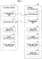
- FIG. 1 is a diagram illustrating the schematic configuration of a vehicle control system 1 according to an embodiment of the invention.
- the vehicle control system 1 includes an in-vehicle device 10 that is provided in a vehicle, and a terminal 20 that can be carried with a user or the like.
- the vehicle control system 1 performs encryption collation processing through a predetermined communication sequence between the in-vehicle device 10 and the terminal 20 to allow the in-vehicle device 10 to authenticate the terminal 20 and to realize predetermined vehicle control (unlocking or locking of a vehicle door, start of an engine, or the like), or switching of a predetermined operation mode in the terminal 20.
- the terminal 20 is a concept including an electronic key dedicated to a vehicle operation, and an electronic apparatus, such as a smartphone, in which predetermined key information downloaded from a server or the like is set.
- an electronic key such as a smartphone
- predetermined key information downloaded from a server or the like is set.
- the vehicle control system 1 will be described in connection with an example where an electronic key is used as the terminal 20.
- the in-vehicle device 10 includes a transmission unit 11, a reception unit 12, a collation controller 13, a signal generation unit 14, and a mode switching controller 15.
- the transmission unit 11 can transmit an electric wave signal (hereinafter, referred to as a "Wake signal”) for activating an electronic key 20 around the vehicle in a predetermined range through a transmission antenna (not shown).
- the transmission unit 11 can transmit an electric wave signal (hereinafter, referred to as a "first signal”) for confirming whether or not the electronic key 20 that returns an electric wave signal (hereinafter, referred to as an acknowledgement (ACK) signal”) as a response to the Wake signal is an authorized electronic key in a predetermined range through the transmission antenna.
- ACK acknowledgement
- the transmission unit 11 can transmit an electric wave signal (hereinafter, referred to as a "third signal”) based on an electric wave signal (hereinafter, referred to as a "second signal”) returned as a response to the first signal in a predetermined range through the transmission antenna.
- the Wake signal, the first signal, and the third signal can be, for example, low frequency (LF) signals.
- the reception unit 12 can receive the ACK signal transmitted from the transmission unit 21 of the electronic key 20 as a response to the Wake signal and the second signal transmitted from the transmission unit 21 of the electronic key 20 as a response to the first signal through a reception antenna (not shown).
- the collation controller 13 can perform encryption collation processing for confirming whether or not the electronic key 20 that transmits the second signal is an authorized electronic key. For example, the collation controller 13 can determine whether or not the electronic key 20 that transmits the second signal is an authorized electronic key by comparing and collating a key-specific identifier ID included in the second signal with an identifier ID registered in a storage unit (not shown) of the in-vehicle device 10 in advance.
- a known technique can be used in the encryption collation processing, and thus, detailed description will not be repeated.
- the signal generation unit 14 can generate the first signal for confirming whether or not the electronic key 20 that returns the ACK signal is an authorized electronic key.
- the first signal can include a switching request of an operation mode of the electronic key 20 according to an instruction of the mode switching controller 15 described below.
- the signal generation unit 14 can generate the third signal including a command for instructing the electronic key 20 to switch the operation mode based on the second signal received from the electronic key 20.
- the mode switching controller 15 determines whether or not a predetermined condition described below is satisfied, and in a case where the predetermined condition is satisfied, instructs the signal generation unit 14 to generate the first signal including a request for appropriately switching the operation mode of the electronic key 20 or the third signal including the command for instructing switching of the operation mode of the electronic key 20.
- the whole or a part of the in-vehicle device 10 described above can be constituted as an electronic control unit (ECU) typically including a central processing unit (CPU), a memory, an input/output interface, and the like.
- the CPU reads and executes a predetermined program stored in the memory, whereby a predetermined function is realized.
- the electronic key 20 includes a transmission unit 21, a reception unit 22, a collation controller 23, a signal generation unit 24, and a mode switching controller 25.
- the reception unit 22 can receive the Wake signal transmitted from the transmission unit 11 of the in-vehicle device 10, the first signal transmitted from the transmission unit 11 of the in-vehicle device 10 as a response to the ACK signal, and the third signal transmitted from the transmission unit 11 of the in-vehicle device 10 as a response to the second signal through the reception antenna (not shown).
- the transmission unit 21 can transmit the ACK signal indicating the activation of the electronic key 20 according to the Wake signal received by the reception unit 22 in a predetermined range through the transmission antenna (not shown).
- the transmission unit 21 can transmit the second signal generated by the signal generation unit 24 described below as a response to the first signal received by the reception unit 22 in a predetermined range through the transmission antenna.
- the ACK signal and the second signal can be, for example, radio frequency (RF) signals.
- the collation controller 23 can perform encryption collation processing for confirming whether or not the in-vehicle device 10 that transmits the first signal is a device that is mounted in a key-registered vehicle. For example, the collation controller 23 can determine whether or not the in-vehicle device 10 that transmits the first signal is a device that is mounted in the key-registered vehicle by comparing and collating an identifier ID included in the first signal and a key-specific identifier ID registered in a storage unit (not shown) of the electronic key 20 in advance.
- a known technique can be used in the encryption collation processing, and thus, detailed description will not be repeated.
- the collation controller 23 can perform encryption collation processing for confirming whether or not the third signal transmitted from the in-vehicle device 10 is an authorized signal including a predetermined value described below transmitted from the in-vehicle device 10 according to a procedure of a predetermined communication sequence. For example, the collation controller 23 can determine whether or not the third signal is an authorized signal transmitted according to the procedure of the predetermined communication sequence by comparing and collating the predetermined value included in the third signal with a predetermined value stored in the storage unit (not shown) of the electronic key 20. For example, in a case where the third signal is encoded with the predetermined value, collation processing may be performed after the third signal is decoded with the predetermined value.
- the signal generation unit 24 can generate the ACK signal as a response to the Wake signal.
- the signal generation unit 24 can generate the second signal as a response to the first signal.
- the second signal is generated based on a predetermined value (hereinafter, referred to as a "predetermined value X") that is updated each time the first signal is received in a case where the switching request of the operation mode of the electronic key 20 is included in the first signal.
- a random number can be used for the predetermined value X.
- a random number that is generated by the logic means each time the electronic key 20 receives the first signal can be acquired as the predetermined value X.
- reception strength (received signal strength indicator (RSSI)) of the first signal received by the electronic key 20 can be used.
- RSSI received signal strength indicator
- the reception strength of the Burst signal that is measured each time the electronic key 20 receives the first signal can be acquired as the predetermined value X.
- the above-described logic means for generating a random number does not need to be additionally provided in the electronic key 20, there is no need to increase the capacity of the microcomputer of the electronic key 20.
- a communication frequency between the electronic key 20 and the in-vehicle device 10 can be used.
- counter means (not shown) can be provided in the electronic key 20, and a counter value that is integrated each time the electronic key 20 receives the first signal can be acquired as the predetermined value X.
- the second signal may be, for example, in a format of the predetermined value X being attached to a prescribed response signal or in a format of the encoded predetermined value X being attached to the prescribed response signal.
- the mode switching controller 25 switches the operation mode of the electronic key 20.
- the electronic key 20 according to the embodiment has at least a predetermined first mode and a predetermined second mode, and the mode switching controller 25 can switch the operation mode of the electronic key 20 from the first mode to the second mode or from the second mode to the first mode based on the instruction of the third signal.
- FIG. 2 illustrates a state in which the vehicle control system 1 according to the embodiment performs a predetermined communication sequence between the in-vehicle device 10 and the electronic key 20, and the operation mode of the electronic key 20 is switched.
- FIG. 3 is a flowchart illustrating a procedure of processing that the in-vehicle device 10 executes.
- FIG. 4 is a flowchart illustrating a procedure of processing that the electronic key 20 executes.
- FIG. 3 will be described. Processing shown in FIG. 3 is repeatedly performed by the in-vehicle device 10.
- Step S301 The Wake signal for activating the electronic key 20 is transmitted at a predetermined timing (Processing [1] of FIG. 2 ). In a case where the Wake signal is transmitted, the process progresses to Step S302.
- Step S302 Determination is made whether or not the ACK signal as a response to the Wake signal is received from the electronic key 20. Specifically, determination is made whether or not the ACK signal is received until a predetermined time elapses after the Wake signal is transmitted in Step S301. In a case where the ACK signal is received (S302, Yes), the process progresses to Step S303. In a case where the ACK signal is not received (S302, No), the process returns to Step S301.
- Step S303 The first signal that is used in encryption collation for confirming whether or not the electronic key 20 that returns the ACK signal is an authorized electronic key is generated. In a case where the first signal is generated, the process progresses to Step S304.
- Step S304 Determination is made whether or not there is a need to switch the operation mode of the electronic key 20 that returns the ACK signal. Whether or not there is a need to switch the operation mode of the electronic key 20 will be described below. In a case where there is a need to switch the operation mode of the electronic key 20 (S304, Yes), the process progresses to Step S305. In a case where there is no need to switch the operation mode of the electronic key 20 (S304, No), the process progresses to Step S306.
- Step S305 The switching request of the operation mode of the electronic key 20 is included in the first signal generated in Step S303, and the first signal is transmitted to the electronic key 20 (Processing [3] of FIG. 2 ). In a case where the first signal is transmitted, the process progresses to Step S307.
- Step S306 The first signal generated in Step S303 is transmitted to the electronic key 20 (Processing [3] of FIG. 2 ). In a case where the first signal is transmitted, the process progresses to Step S307.
- Step S307 Determination is made whether or not the second signal as a response to the first signal is received from the electronic key 20. Specifically, determination is made whether or not the second signal is received until a predetermined time elapses after the first signal is transmitted in Step S305 or S306. In a case where the second signal is received (S307, Yes), the process progresses to Step S308. In a case where the second signal is not received (S307, No), the process returns to Step S301.
- Step S308 Encryption collation of the second signal is performed and a collation result is determined. Specifically, determination is made whether or not the second signal is a response from the authorized electronic key 20. In a case where the result of encryption collation is OK (S308, OK), the process progresses to Step S309. In a case where the result of encryption collation is NG (S308, NG), the process returns to
- Step S309 Determination is made whether or not there is a need to switch the operation mode of the electronic key 20 where the result of encryption collation is OK. In a case where there is a need to switch the operation mode of the electronic key 20 (S309, Yes), the process progresses to Step S310. In a case where there is no need to switch the operation mode of the electronic key 20 (S309, No), the process returns to Step S301.
- Step S310 The third signal for use in encryption collation is generated based on the second signal and is transmitted to the electronic key 20 (Processing [5] of FIG. 2 ). Specifically, a signal including a command for switching the operation mode of the electronic key 20 is generated as the third signal based on the predetermined value X used in generating the second signal. In a case where the third signal is transmitted, the process returns to Step S301.
- FIG. 4 will be described. Processing shown in FIG. 4 is repeatedly performed by the electronic key 20.
- Step S401 Determination is made whether or not the Wake signal is received from the in-vehicle device 10. In a case where the Wake signal is received (S401, Yes), the process progresses to Step S402. In a case where the Wake signal is not received (S401, No), the process returns to Step S401.
- Step S402 In order to notify that the electronic key 20 is activated according to the Wake signal, the ACK signal is transmitted to the in-vehicle device 10 (Processing [2] of FIG. 2 ). In a case where the ACK signal is transmitted, the process progresses to Step S403.
- Step S403 Determination is made whether or not the first signal is received from the in-vehicle device 10. In a case where the first signal is received (S302, Yes), the process progresses to Step S404. In a case where the first signal is not received (S302, No), the process returns to Step S401.
- Step S404 Encryption collation of the first signal is performed and a collation result is determined. Specifically, determination is made whether or not the first signal is a signal transmitted to the electronic key 20. In a case where the result of encryption collation is OK (S404, OK), the process progresses to Step S405. In a case where the result of encryption collation is NG (S404, NG), the process returns to Step S401.
- Step S405 Determination is made whether or not a request for switching the operation mode of the electronic key 20 is included in the first signal. In a case where the request for switching the operation mode of the electronic key 20 is included (S405, Yes), the process progresses to Step S406. In a case where the request for switching the operation mode of the electronic key 20 is not included (S405, No), the process progresses to Step S407.
- Step S406 The predetermined value X is acquired and stored in a predetermined storage unit. In a case where the predetermined value X is acquired and stored in the predetermined storage unit, the process progresses to Step S407.
- Step S407 The second signal as a response to the first signal is generated based on the predetermined value X, and the second signal based on the predetermined value X is transmitted to the in-vehicle device 10 (Processing [4] of FIG. 2 ). In a case where the second signal is transmitted, the process progresses to Step S409.
- Step S408 An original response signal is transmitted to the in-vehicle device 10 as the second signal. In a case where the second signal is transmitted, the process progresses to Step S409.
- Step S409 Determination is made whether or not the third signal as a response to the second signal is received from the in-vehicle device 10. Specifically, determination is made whether or not the third signal is received until a predetermined time elapses after the second signal is transmitted in Step S407 or S408. In a case where the third signal is received (S409, Yes), the process progresses to Step S410. In a case where the third signal is not received (S409, No), the process progresses to Step S412.
- Step S410 Encryption collation of the third signal is performed and a collation result is determined. Specifically, encryption collation of the third signal is performed using the predetermined value X, and determination is made whether or not the third signal is an authorized signal including the predetermined value X transmitted from the in-vehicle device 10 according to the procedure of the communication sequence.
- the result of encryption collation is OK (S410, OK)
- the process progresses to Step S411
- the result of encryption collation is NG (S410, NG)
- the process progresses to Step S412.
- Step S411 Determination is made that the third signal is an authorized signal transmitted from the in-vehicle device 10, and the operation mode of the electronic key 20 is switched from the first mode to the second mode or from the second mode to the first mode (Processing [6] of FIG. 2 ). In a case where the operation mode of the electronic key 20 is switched, the process progresses to Step S412.
- Step S412 The predetermined value X stored in the predetermined storage unit is erased. In a case where the predetermined value X is erased, the process returns to Step S401.
- FIG. 5 is an example of a state transition diagram of the electronic key 20 in the vehicle control system 1 according to the embodiment of the invention.
- the electronic key 20 has a first mode, a second mode, a third mode, a fourth mode, and a fifth mode as a switchable operation mode.
- the electronic key 20 further includes, for example, a vibration detection unit 26 that detects vibration of the electronic key 20, such as an acceleration sensor.
- the first mode is a mode that is set based on getting-off determination in the in-vehicle device 10, and is, for example, an extra-vehicle cabin mode.
- the operation mode of the electronic key 20 is switched from the first mode and the fifth mode, and state transition is made.
- the operation mode of the electronic key 20 is switched from the first mode to the second mode, and state transition is made.
- the second mode is a mode that is set based on getting-in determination in the in-vehicle device 10, and is, for example, an intra-vehicle cabin mode.
- the operation mode of the electronic key 20 is switched from the second mode to the first mode, and state transition is made.
- the operation mode of the electronic key 20 is switched from the second mode to the first mode and the fifth mode in order.
- the operation mode of the electronic key 20 is switched from the second mode to the fifth mode (a dotted-line arrow of FIG. 5 ).
- the third mode is a mode that is set based on a state of the vibration detection unit 26. For example, switching to the third mode is performed when an abnormality of the vibration detection unit 26 is detected in the first mode and the second mode. Release of the third mode is performed when detection is made that the vibration detection unit 26 returns to normal.
- the operation mode of the electronic key 20 that is switched when the vibration detection unit 26 returns to normal may be appropriately one of the first mode and the second mode. Accordingly, in the third mode, communication between the electronic key 20 and the in-vehicle device 10 is not restricted without regard to the result of vibration detection in the vibration detection unit 26.
- the fourth mode is a mode that is set based on a predetermined operation.
- communication between the electronic key 20 and the in-vehicle device 10 is restricted compared to the first mode and the second mode.
- switching to the fourth mode is performed with a special operation (first input operation) determined in advance, such as depression of a dedicated button, in the first mode and the second mode.
- release of the fourth mode is performed with a switch operation (second input operation) determined in advance.
- the operation mode of the electronic key 20 that is switched by the switch operation may be appropriately one of the first mode and the second mode.
- the third mode and the fourth mode may be switched to each other by the special operation (first input operation) or the switch operation (second input operation).
- the fifth mode is a mode that is set based on the result of vibration detection in the vibration detection unit 26.
- communication between the electronic key 20 and the in-vehicle device 10 is restricted compared to the first mode and the second mode.
- a content of restriction in the fifth mode may be disabling reception of an electric wave signal from the in-vehicle device 10, disabling a response to an electric wave signal received from the in-vehicle device 10, or a combination thereof.
- vibration is detected by the vibration detection unit 26, or a switch operation (second input operation) determined in advance, such as depression of a door unlock button, is performed, whereby the operation mode of the electronic key 20 is switched from the fifth mode to the first mode, and state transition is made.
- the electronic key 20 in a case where the first signal including the switching request of the operation mode is received from the in-vehicle device 10, the electronic key 20 generates the second signal based on the predetermined value X (the random number generated by the electronic key 20, the reception strength of the first signal, or the communication frequency between the electronic key 20 and the in-vehicle device 10) that is updated each time the first signal is received, and transmits the second signal to the in-vehicle device 10.
- the electronic key 20 switches the operation mode as long as the third signal including the command for instructing mode switching generated based on the latest predetermined value X can be received from the in-vehicle device 10 as a response of the transmitted second signal.
- the third signal including the command for instructing mode switching to be communicated between the in-vehicle device 10 and the electronic key 20 is copied by a third party, in a case where the third signal is used in an unauthorized manner when one communication sequence or more regarding communication between the in-vehicle device 10 and the electronic key 20 has elapsed after the third signal is copied, determination is made in the electronic key 20 that the third signal is not a response to the second signal generated based on the latest predetermined value X.
- the invention is usable in a vehicle control system that an in-vehicle device and an electronic key perform communication to control a vehicle, or the like.
- the invention is not limited to the above-described embodiment, and various alterations may be made without departing from the spirit and scope of the invention described in the claims.
Landscapes
- Engineering & Computer Science (AREA)
- Mechanical Engineering (AREA)
- Computer Networks & Wireless Communication (AREA)
- Signal Processing (AREA)
- Human Computer Interaction (AREA)
- Physics & Mathematics (AREA)
- General Physics & Mathematics (AREA)
- Automation & Control Theory (AREA)
- Transportation (AREA)
- Lock And Its Accessories (AREA)
- Selective Calling Equipment (AREA)
- Transceivers (AREA)
Abstract
Description
- The present invention relates to a terminal (hereinafter, referred to as a "terminal") that performs communication with an in-vehicle device to control a vehicle, a vehicle control system including the terminal and the in-vehicle device, and a vehicle control method that the vehicle control system executes.
- For example, Japanese Unexamined Patent Application Publication No.
9-004292 JP 9-004292 A 2012-144906 JP 2012-144906 A - In the techniques described in
JP 9-004292 A JP 2012-144906 A - The invention provides a terminal, a vehicle control system, and a vehicle control method capable of further suppressing switching of an operation mode of a terminal, such as an electronic key, at a timing unintended by a user.
- A first aspect of the invention relates to a terminal that performs communication with an in-vehicle device to control a vehicle. The terminal includes a controller, a reception unit, a generation unit, and a transmission unit. The controller is configured to switch and control an operation mode of the terminal to at least a predetermined first mode or a predetermined second mode. The reception unit is configured to receive a first signal including a switching request of the operation mode of the terminal from the in-vehicle device. The generation unit is configured to update a predetermined value with the reception of the first signal and generate a second signal based on the updated predetermined value. The transmission unit is configured to transmit the second signal to the in-vehicle device. In a case where a third signal including a command for instructing switching of the operation mode of the terminal received by the reception unit is a response to the second signal, the controller is configured to switch the operation mode of the terminal from the predetermined first mode to the predetermined second mode or from the predetermined second mode to the predetermined first mode.
- In the terminal according to the first aspect of the invention, in a case where the first signal including the switching request of the operation mode of the terminal is received from the in-vehicle device, the second signal based on the predetermined value updated with the reception of the first signal is generated and transmitted to the in-vehicle device. In a case where the third signal including the command for instructing switching of the operation mode of the terminal generated based on the predetermined value from the terminal can be received as the response of the second signal from the in-vehicle device, the operation mode of the terminal is switched.
- With the above-described control, even though the third signal including the command for instructing switching of the mode of the terminal is copied by a third party, in a case where the third signal is used in an unauthorized manner when one communication sequence or more has elapsed after the third signal is copied, determination is made that the third signal is not a response to the second signal transmitted before the third signal is received. Accordingly, it is possible to further suppress switching of the operation mode of the terminal at a timing unintended by a user.
- In the terminal according to the first aspect of the invention, the predetermined value may be a random number that is generated by the terminal.
- In the terminal according to the first aspect of the invention, the predetermined value may be reception strength of the first signal.
- In the terminal according to the first aspect of the invention, the predetermined value may be a communication frequency between the terminal and the in-vehicle device.
- In a case where the predetermined value described above is set, it is possible to easily acquire a value that is updated with the reception of the first signal.
- The terminal according to the first aspect of the invention may further include a vibration detection unit configured to detect vibration of the terminal. The controller may be configured to, in the first mode, restrict communication with the in-vehicle device in a case where vibration is not detected in the vibration detection unit for a predetermined time, and, in the second mode, restrict communication with the in-vehicle device in a case where vibration is not detected in the vibration detection unit for a time longer than the predetermined time.
- With the above-described control, even though vibration of the terminal is not detected, the operation mode of the terminal is not switched instantly from the first mode or the second mode to another mode. Accordingly, it is possible to further suppress frequent switching of the operation mode of the terminal in a case where the presence or absence of vibration of the terminal is repeatedly detected in a period shorter than the predetermined time.
- In the terminal according to the first aspect of the invention, the controller may be configured to, when the first mode or the second mode is executed, in a case where an abnormality occurs in the vibration detection unit, switch the operation mode of the terminal to a third mode as an operation mode where communication with the in-vehicle device is performed, regardless of a result of vibration detection in the vibration detection unit.
- In the terminal according to the first aspect of the invention, the controller may be configured to, when the operation mode of the terminal is the third mode, i) in a case where the abnormality of the vibration detection unit is eliminated, switch the operation mode of the terminal to the first mode or the second mode, and ii) in a case where a first input operation on the terminal is detected, switch the operation mode of the terminal to a fourth mode as an operation mode where communication with the in-vehicle device is restricted.
- In the terminal according to the first aspect of the invention, the controller may be configured to, when the fourth mode is executed, solely in a case where a second input operation on the terminal is detected, release the fourth mode.
- In the terminal according to the first aspect of the invention, the vibration detection unit of the terminal may be configured to detect vibration using an acceleration sensor.
- With the above-described control, it is possible to switch the operation mode of the terminal to an optimum mode constantly.
- A second aspect of the invention relates to a vehicle control method that a terminal configured to perform communication with an in-vehicle device to control a vehicle executes. The vehicle control method includes receiving a first signal including a switching request of an operation mode of the terminal from the in-vehicle device, updating a predetermined value with the reception of the first signal, generating a second signal based on the updated predetermined value, transmitting the second signal to the in-vehicle device, receiving a third signal including a command for instructing switching of the operation mode of the terminal from the in-vehicle device, and in a case where the third signal is a response to the second signal, switching the operation mode of the terminal from a predetermined first mode to a predetermined second mode or from the predetermined second mode to the predetermined first mode.
- A third aspect of the invention relates to a vehicle control system including an in-vehicle device and a terminal. The in-vehicle device includes a first transmission unit, a first reception unit, a first generation unit, and a second transmission unit. The first transmission unit is configured to, in a case of switching an operation mode of the terminal, transmit a first signal including a switching request of the operation mode of the terminal to the terminal. The first reception unit is configured to receive a second signal as a response to the first signal from the terminal. The first generation unit is configured to generate a third signal including a command for instructing switching of the operation mode of the terminal based on the second signal. The second transmission unit is configured to transmit the third signal to the terminal. The terminal includes a second reception unit, a second generation unit, a third transmission unit, a third reception unit, and a controller. The second reception unit is configured to receive the first signal from the in-vehicle device. The second generation unit is configured to update a predetermined value with the reception of the first signal and generate the second signal based on the updated predetermined value. The third transmission unit is configured to transmit the second signal to the in-vehicle device. The third reception unit is configured to receive the third signal from the in-vehicle device. The controller is configured to, in a case where the third signal is a response to the second signal, switch the operation mode of the terminal from a predetermined first mode to a predetermined second mode or from the predetermined second mode to the predetermined first mode. The in-vehicle device and the terminal perform communication to control a vehicle.
- With the control according to the second aspect and the third aspect of the invention, even though the third signal copied by a third party is used in an unauthorized manner, determination is also made that the third signal is not a response to the second signal transmitted before the third signal is received. Accordingly, it is possible to further suppress switching of the operation mode of the terminal at a timing unintended by a user.
- With the terminal, the vehicle control system, and the vehicle control method according to the aspects of the invention, it is possible to further suppress switching of an operation mode of a terminal, such as an electronic key, at a timing unintended by a user.
- Features, advantages, and technical and industrial significance of exemplary embodiments of the invention will be described below with reference to the accompanying drawings, in which like numerals denote like elements, and wherein:
-
FIG. 1 is a diagram illustrating the schematic configuration of a vehicle control system according to an embodiment; -
FIG. 2 shows an example of a communication sequence that is executed between an in-vehicle device and a terminal; -
FIG. 3 is a flowchart illustrating a procedure of processing that the in-vehicle device executes; -
FIG. 4 is a flowchart illustrating a procedure of processing that the terminal executes; and -
FIG. 5 shows an example of a state transition diagram of the terminal in the vehicle control system according to the embodiment. - In a vehicle control system including an in-vehicle device and a terminal of the invention, in a case where the terminal receives a switching request of an operation mode from the in-vehicle device, a signal based on a predetermined value updated every time is generated and transmitted to the in-vehicle device. The terminal switches the operation mode in a case where an instruction command based on the latest predetermined value can be received as a response to the signal from the in-vehicle device.
-
FIG. 1 is a diagram illustrating the schematic configuration of avehicle control system 1 according to an embodiment of the invention. InFIG. 1 , thevehicle control system 1 includes an in-vehicle device 10 that is provided in a vehicle, and aterminal 20 that can be carried with a user or the like. - The
vehicle control system 1 performs encryption collation processing through a predetermined communication sequence between the in-vehicle device 10 and theterminal 20 to allow the in-vehicle device 10 to authenticate theterminal 20 and to realize predetermined vehicle control (unlocking or locking of a vehicle door, start of an engine, or the like), or switching of a predetermined operation mode in theterminal 20. - The terminal 20 is a concept including an electronic key dedicated to a vehicle operation, and an electronic apparatus, such as a smartphone, in which predetermined key information downloaded from a server or the like is set. In the following embodiment, the
vehicle control system 1 will be described in connection with an example where an electronic key is used as the terminal 20. - In
FIG. 1 , the in-vehicle device 10 includes a transmission unit 11, areception unit 12, acollation controller 13, asignal generation unit 14, and amode switching controller 15. - The transmission unit 11 can transmit an electric wave signal (hereinafter, referred to as a "Wake signal") for activating an
electronic key 20 around the vehicle in a predetermined range through a transmission antenna (not shown). The transmission unit 11 can transmit an electric wave signal (hereinafter, referred to as a "first signal") for confirming whether or not the electronic key 20 that returns an electric wave signal (hereinafter, referred to as an acknowledgement (ACK) signal") as a response to the Wake signal is an authorized electronic key in a predetermined range through the transmission antenna. The transmission unit 11 can transmit an electric wave signal (hereinafter, referred to as a "third signal") based on an electric wave signal (hereinafter, referred to as a "second signal") returned as a response to the first signal in a predetermined range through the transmission antenna. The Wake signal, the first signal, and the third signal can be, for example, low frequency (LF) signals. - The
reception unit 12 can receive the ACK signal transmitted from thetransmission unit 21 of the electronic key 20 as a response to the Wake signal and the second signal transmitted from thetransmission unit 21 of the electronic key 20 as a response to the first signal through a reception antenna (not shown). - The
collation controller 13 can perform encryption collation processing for confirming whether or not the electronic key 20 that transmits the second signal is an authorized electronic key. For example, thecollation controller 13 can determine whether or not the electronic key 20 that transmits the second signal is an authorized electronic key by comparing and collating a key-specific identifier ID included in the second signal with an identifier ID registered in a storage unit (not shown) of the in-vehicle device 10 in advance. A known technique can be used in the encryption collation processing, and thus, detailed description will not be repeated. - The
signal generation unit 14 can generate the first signal for confirming whether or not the electronic key 20 that returns the ACK signal is an authorized electronic key. The first signal can include a switching request of an operation mode of the electronic key 20 according to an instruction of themode switching controller 15 described below. Thesignal generation unit 14 can generate the third signal including a command for instructing the electronic key 20 to switch the operation mode based on the second signal received from theelectronic key 20. - The
mode switching controller 15 determines whether or not a predetermined condition described below is satisfied, and in a case where the predetermined condition is satisfied, instructs thesignal generation unit 14 to generate the first signal including a request for appropriately switching the operation mode of the electronic key 20 or the third signal including the command for instructing switching of the operation mode of theelectronic key 20. - The whole or a part of the in-
vehicle device 10 described above can be constituted as an electronic control unit (ECU) typically including a central processing unit (CPU), a memory, an input/output interface, and the like. In the electronic control unit, the CPU reads and executes a predetermined program stored in the memory, whereby a predetermined function is realized. - In
FIG. 1 , theelectronic key 20 includes atransmission unit 21, areception unit 22, acollation controller 23, asignal generation unit 24, and amode switching controller 25. - The
reception unit 22 can receive the Wake signal transmitted from the transmission unit 11 of the in-vehicle device 10, the first signal transmitted from the transmission unit 11 of the in-vehicle device 10 as a response to the ACK signal, and the third signal transmitted from the transmission unit 11 of the in-vehicle device 10 as a response to the second signal through the reception antenna (not shown). - The
transmission unit 21 can transmit the ACK signal indicating the activation of the electronic key 20 according to the Wake signal received by thereception unit 22 in a predetermined range through the transmission antenna (not shown). Thetransmission unit 21 can transmit the second signal generated by thesignal generation unit 24 described below as a response to the first signal received by thereception unit 22 in a predetermined range through the transmission antenna. The ACK signal and the second signal can be, for example, radio frequency (RF) signals. - The
collation controller 23 can perform encryption collation processing for confirming whether or not the in-vehicle device 10 that transmits the first signal is a device that is mounted in a key-registered vehicle. For example, thecollation controller 23 can determine whether or not the in-vehicle device 10 that transmits the first signal is a device that is mounted in the key-registered vehicle by comparing and collating an identifier ID included in the first signal and a key-specific identifier ID registered in a storage unit (not shown) of the electronic key 20 in advance. A known technique can be used in the encryption collation processing, and thus, detailed description will not be repeated. - The
collation controller 23 can perform encryption collation processing for confirming whether or not the third signal transmitted from the in-vehicle device 10 is an authorized signal including a predetermined value described below transmitted from the in-vehicle device 10 according to a procedure of a predetermined communication sequence. For example, thecollation controller 23 can determine whether or not the third signal is an authorized signal transmitted according to the procedure of the predetermined communication sequence by comparing and collating the predetermined value included in the third signal with a predetermined value stored in the storage unit (not shown) of theelectronic key 20. For example, in a case where the third signal is encoded with the predetermined value, collation processing may be performed after the third signal is decoded with the predetermined value. - The
signal generation unit 24 can generate the ACK signal as a response to the Wake signal. Thesignal generation unit 24 can generate the second signal as a response to the first signal. The second signal is generated based on a predetermined value (hereinafter, referred to as a "predetermined value X") that is updated each time the first signal is received in a case where the switching request of the operation mode of theelectronic key 20 is included in the first signal. - For the predetermined value X, for example, a random number can be used. For example, in a case where logic means (not shown) for generating a random number is provided in the electronic key 20 in advance, a random number that is generated by the logic means each time the
electronic key 20 receives the first signal can be acquired as the predetermined value X. - For the predetermined value X, for example, reception strength (received signal strength indicator (RSSI)) of the first signal received by the electronic key 20 can be used. For example, in a case where a Burst signal (not shown) for RSSI measurement is included in the first signal transmitted from the in-
vehicle device 10 in advance, and means (not shown) for measuring reception strength is provided in the electronic key 20 in advance, the reception strength of the Burst signal that is measured each time theelectronic key 20 receives the first signal can be acquired as the predetermined value X. In this case, since the above-described logic means for generating a random number does not need to be additionally provided in theelectronic key 20, there is no need to increase the capacity of the microcomputer of theelectronic key 20. - For the predetermined value X, for example, a communication frequency between the
electronic key 20 and the in-vehicle device 10 can be used. For example, counter means (not shown) can be provided in theelectronic key 20, and a counter value that is integrated each time theelectronic key 20 receives the first signal can be acquired as the predetermined value X. - The second signal may be, for example, in a format of the predetermined value X being attached to a prescribed response signal or in a format of the encoded predetermined value X being attached to the prescribed response signal.
- In a case where the
collation controller 23 determines that the third signal is an authorized signal transmitted according to the procedure of the predetermined communication sequence, themode switching controller 25 switches the operation mode of theelectronic key 20. The electronic key 20 according to the embodiment has at least a predetermined first mode and a predetermined second mode, and themode switching controller 25 can switch the operation mode of the electronic key 20 from the first mode to the second mode or from the second mode to the first mode based on the instruction of the third signal. -
FIG. 2 illustrates a state in which thevehicle control system 1 according to the embodiment performs a predetermined communication sequence between the in-vehicle device 10 and theelectronic key 20, and the operation mode of theelectronic key 20 is switched.FIG. 3 is a flowchart illustrating a procedure of processing that the in-vehicle device 10 executes.FIG. 4 is a flowchart illustrating a procedure of processing that theelectronic key 20 executes. - First,
FIG. 3 will be described. Processing shown inFIG. 3 is repeatedly performed by the in-vehicle device 10. - Step S301: The Wake signal for activating the
electronic key 20 is transmitted at a predetermined timing (Processing [1] ofFIG. 2 ). In a case where the Wake signal is transmitted, the process progresses to Step S302. - Step S302: Determination is made whether or not the ACK signal as a response to the Wake signal is received from the
electronic key 20. Specifically, determination is made whether or not the ACK signal is received until a predetermined time elapses after the Wake signal is transmitted in Step S301. In a case where the ACK signal is received (S302, Yes), the process progresses to Step S303. In a case where the ACK signal is not received (S302, No), the process returns to Step S301. - Step S303: The first signal that is used in encryption collation for confirming whether or not the electronic key 20 that returns the ACK signal is an authorized electronic key is generated. In a case where the first signal is generated, the process progresses to Step S304.
- Step S304: Determination is made whether or not there is a need to switch the operation mode of the electronic key 20 that returns the ACK signal. Whether or not there is a need to switch the operation mode of the electronic key 20 will be described below. In a case where there is a need to switch the operation mode of the electronic key 20 (S304, Yes), the process progresses to Step S305. In a case where there is no need to switch the operation mode of the electronic key 20 (S304, No), the process progresses to Step S306.
- Step S305: The switching request of the operation mode of the
electronic key 20 is included in the first signal generated in Step S303, and the first signal is transmitted to the electronic key 20 (Processing [3] ofFIG. 2 ). In a case where the first signal is transmitted, the process progresses to Step S307. - Step S306: The first signal generated in Step S303 is transmitted to the electronic key 20 (Processing [3] of
FIG. 2 ). In a case where the first signal is transmitted, the process progresses to Step S307. - Step S307: Determination is made whether or not the second signal as a response to the first signal is received from the
electronic key 20. Specifically, determination is made whether or not the second signal is received until a predetermined time elapses after the first signal is transmitted in Step S305 or S306. In a case where the second signal is received (S307, Yes), the process progresses to Step S308. In a case where the second signal is not received (S307, No), the process returns to Step S301. - Step S308: Encryption collation of the second signal is performed and a collation result is determined. Specifically, determination is made whether or not the second signal is a response from the authorized
electronic key 20. In a case where the result of encryption collation is OK (S308, OK), the process progresses to Step S309. In a case where the result of encryption collation is NG (S308, NG), the process returns to - Step S309: Determination is made whether or not there is a need to switch the operation mode of the electronic key 20 where the result of encryption collation is OK. In a case where there is a need to switch the operation mode of the electronic key 20 (S309, Yes), the process progresses to Step S310. In a case where there is no need to switch the operation mode of the electronic key 20 (S309, No), the process returns to Step S301.
- Step S310: The third signal for use in encryption collation is generated based on the second signal and is transmitted to the electronic key 20 (Processing [5] of
FIG. 2 ). Specifically, a signal including a command for switching the operation mode of theelectronic key 20 is generated as the third signal based on the predetermined value X used in generating the second signal. In a case where the third signal is transmitted, the process returns to Step S301. -
FIG. 4 will be described. Processing shown inFIG. 4 is repeatedly performed by theelectronic key 20. - Step S401: Determination is made whether or not the Wake signal is received from the in-
vehicle device 10. In a case where the Wake signal is received (S401, Yes), the process progresses to Step S402. In a case where the Wake signal is not received (S401, No), the process returns to Step S401. - Step S402: In order to notify that the
electronic key 20 is activated according to the Wake signal, the ACK signal is transmitted to the in-vehicle device 10 (Processing [2] ofFIG. 2 ). In a case where the ACK signal is transmitted, the process progresses to Step S403. - Step S403: Determination is made whether or not the first signal is received from the in-
vehicle device 10. In a case where the first signal is received (S302, Yes), the process progresses to Step S404. In a case where the first signal is not received (S302, No), the process returns to Step S401. - Step S404: Encryption collation of the first signal is performed and a collation result is determined. Specifically, determination is made whether or not the first signal is a signal transmitted to the
electronic key 20. In a case where the result of encryption collation is OK (S404, OK), the process progresses to Step S405. In a case where the result of encryption collation is NG (S404, NG), the process returns to Step S401. - Step S405: Determination is made whether or not a request for switching the operation mode of the
electronic key 20 is included in the first signal. In a case where the request for switching the operation mode of theelectronic key 20 is included (S405, Yes), the process progresses to Step S406. In a case where the request for switching the operation mode of theelectronic key 20 is not included (S405, No), the process progresses to Step S407. - Step S406: The predetermined value X is acquired and stored in a predetermined storage unit. In a case where the predetermined value X is acquired and stored in the predetermined storage unit, the process progresses to Step S407.
- Step S407: The second signal as a response to the first signal is generated based on the predetermined value X, and the second signal based on the predetermined value X is transmitted to the in-vehicle device 10 (Processing [4] of
FIG. 2 ). In a case where the second signal is transmitted, the process progresses to Step S409. - Step S408: An original response signal is transmitted to the in-
vehicle device 10 as the second signal. In a case where the second signal is transmitted, the process progresses to Step S409. - Step S409: Determination is made whether or not the third signal as a response to the second signal is received from the in-
vehicle device 10. Specifically, determination is made whether or not the third signal is received until a predetermined time elapses after the second signal is transmitted in Step S407 or S408. In a case where the third signal is received (S409, Yes), the process progresses to Step S410. In a case where the third signal is not received (S409, No), the process progresses to Step S412. - Step S410: Encryption collation of the third signal is performed and a collation result is determined. Specifically, encryption collation of the third signal is performed using the predetermined value X, and determination is made whether or not the third signal is an authorized signal including the predetermined value X transmitted from the in-
vehicle device 10 according to the procedure of the communication sequence. In a case where the result of encryption collation is OK (S410, OK), the process progresses to Step S411. In a case where the result of encryption collation is NG (S410, NG), the process progresses to Step S412. - Step S411: Determination is made that the third signal is an authorized signal transmitted from the in-
vehicle device 10, and the operation mode of theelectronic key 20 is switched from the first mode to the second mode or from the second mode to the first mode (Processing [6] ofFIG. 2 ). In a case where the operation mode of theelectronic key 20 is switched, the process progresses to Step S412. - Step S412: The predetermined value X stored in the predetermined storage unit is erased. In a case where the predetermined value X is erased, the process returns to Step S401.
- In the embodiment, an example where the electronic key 20 switches the operation mode according to the command for instructing mode switching transmitted from the in-
vehicle device 10 has been described. Here, a condition when the operation mode of theelectronic key 20 is switched will be described referring toFIG. 5 in connection with a specific example. -
FIG. 5 is an example of a state transition diagram of the electronic key 20 in thevehicle control system 1 according to the embodiment of the invention. In the specific example, theelectronic key 20 has a first mode, a second mode, a third mode, a fourth mode, and a fifth mode as a switchable operation mode. The electronic key 20 further includes, for example, avibration detection unit 26 that detects vibration of theelectronic key 20, such as an acceleration sensor. - The first mode is a mode that is set based on getting-off determination in the in-
vehicle device 10, and is, for example, an extra-vehicle cabin mode. In the first mode, in a case where vibration of theelectronic key 20 is not detected by thevibration detection unit 26 for a predetermined first time N1, the operation mode of theelectronic key 20 is switched from the first mode and the fifth mode, and state transition is made. In the first mode, in a case where getting-in determination is made in the in-vehicle device 10, the operation mode of theelectronic key 20 is switched from the first mode to the second mode, and state transition is made. - The second mode is a mode that is set based on getting-in determination in the in-
vehicle device 10, and is, for example, an intra-vehicle cabin mode. In the second mode, in a case where vibration of theelectronic key 20 is not detected by thevibration detection unit 26 for a predetermined second time N2 or in a case where getting-off determination is made in the in-vehicle device 10, the operation mode of theelectronic key 20 is switched from the second mode to the first mode, and state transition is made. In the former case, in the second mode, in a case where vibration of theelectronic key 20 is not detected by thevibration detection unit 26 for the first time N1 besides the second time N2, the operation mode of theelectronic key 20 is switched from the second mode to the first mode and the fifth mode in order. Accordingly, in the second mode, in a case where vibration of theelectronic key 20 is not detected by thevibration detection unit 26 for a predetermined third time N3 (= the first time N1 + the second time N2) longer than the first time N1, the operation mode of theelectronic key 20 is switched from the second mode to the fifth mode (a dotted-line arrow ofFIG. 5 ). - The third mode is a mode that is set based on a state of the
vibration detection unit 26. For example, switching to the third mode is performed when an abnormality of thevibration detection unit 26 is detected in the first mode and the second mode. Release of the third mode is performed when detection is made that thevibration detection unit 26 returns to normal. The operation mode of the electronic key 20 that is switched when thevibration detection unit 26 returns to normal may be appropriately one of the first mode and the second mode. Accordingly, in the third mode, communication between theelectronic key 20 and the in-vehicle device 10 is not restricted without regard to the result of vibration detection in thevibration detection unit 26. - The fourth mode is a mode that is set based on a predetermined operation. In the fourth mode, communication between the
electronic key 20 and the in-vehicle device 10 is restricted compared to the first mode and the second mode. For example, switching to the fourth mode is performed with a special operation (first input operation) determined in advance, such as depression of a dedicated button, in the first mode and the second mode. Release of the fourth mode is performed with a switch operation (second input operation) determined in advance. The operation mode of the electronic key 20 that is switched by the switch operation may be appropriately one of the first mode and the second mode. - The third mode and the fourth mode may be switched to each other by the special operation (first input operation) or the switch operation (second input operation).
- The fifth mode is a mode that is set based on the result of vibration detection in the
vibration detection unit 26. In the fifth mode, communication between theelectronic key 20 and the in-vehicle device 10 is restricted compared to the first mode and the second mode. A content of restriction in the fifth mode may be disabling reception of an electric wave signal from the in-vehicle device 10, disabling a response to an electric wave signal received from the in-vehicle device 10, or a combination thereof. In the fifth mode, vibration is detected by thevibration detection unit 26, or a switch operation (second input operation) determined in advance, such as depression of a door unlock button, is performed, whereby the operation mode of theelectronic key 20 is switched from the fifth mode to the first mode, and state transition is made. - In the above-described state transition, after vibration of the
electronic key 20 is not detected for the first time N1 in the first mode, switching to the fifth mode is performed. After vibration of theelectronic key 20 is not detected for the third time N3 in the second mode, switching to the fifth mode is performed. Accordingly, it is possible to further suppress frequent switching of the operation mode of the electronic key 20 in a case where the presence or absence of vibration of theelectronic key 20 is repeatedly detected in a period shorter than a predetermined time. - As described above, with the
vehicle control system 1 according to the embodiment of the invention, in a case where the first signal including the switching request of the operation mode is received from the in-vehicle device 10, theelectronic key 20 generates the second signal based on the predetermined value X (the random number generated by theelectronic key 20, the reception strength of the first signal, or the communication frequency between theelectronic key 20 and the in-vehicle device 10) that is updated each time the first signal is received, and transmits the second signal to the in-vehicle device 10. The electronic key 20 switches the operation mode as long as the third signal including the command for instructing mode switching generated based on the latest predetermined value X can be received from the in-vehicle device 10 as a response of the transmitted second signal. - With the above-described control, even though the third signal including the command for instructing mode switching to be communicated between the in-
vehicle device 10 and theelectronic key 20 is copied by a third party, in a case where the third signal is used in an unauthorized manner when one communication sequence or more regarding communication between the in-vehicle device 10 and theelectronic key 20 has elapsed after the third signal is copied, determination is made in the electronic key 20 that the third signal is not a response to the second signal generated based on the latest predetermined value X. - Accordingly, it is possible to further suppress switching of the operation mode of the electronic key 20 at a timing unintended by the user.
- The invention is usable in a vehicle control system that an in-vehicle device and an electronic key perform communication to control a vehicle, or the like. In addition, the invention is not limited to the above-described embodiment, and various alterations may be made without departing from the spirit and scope of the invention described in the claims.
Claims (11)
- A terminal (20) that performs communication with an in-vehicle device (10) to control a vehicle, the terminal (20) comprising:a controller configured to switch and control an operation mode of the terminal (20) to at least a predetermined first mode or a predetermined second mode;a reception unit configured to receive a first signal including a switching request of the operation mode of the terminal (20) from the in-vehicle device (10);a generation unit configured to update a predetermined value with the reception of the first signal and generate a second signal based on the updated predetermined value; anda transmission unit (21) configured to transmit the second signal to the in-vehicle device (10),wherein, in a case where a third signal including a command for instructing switching of the operation mode of the terminal (20) received by the reception unit is a response to the second signal, the controller is configured to switch the operation mode of the terminal (20) from the predetermined first mode to the predetermined second mode or from the predetermined second mode to the predetermined first mode.
- The terminal (20) according to claim 1, wherein the predetermined value is a random number that is generated by the terminal (20).
- The terminal (20) according to claim 1, wherein the predetermined value is reception strength of the first signal.
- The terminal (20) according to claim 1, wherein the predetermined value is a communication frequency between the terminal (20) and the in-vehicle device (10).
- The terminal (20) according to any one of claims 1 to 4, further comprising a vibration detection unit (26) configured to detect vibration of the terminal (20),
wherein the controller is configured toin the first mode, restrict communication with the in-vehicle device (10) in a case where vibration is not detected in the vibration detection unit (26) for a predetermined time, andin the second mode, restrict communication with the in-vehicle device (10) in a case where vibration is not detected in the vibration detection unit (26) for a time longer than the predetermined time. - The terminal (20) according to claim 5, wherein the controller is configured to, when the first mode or the second mode is executed, in a case where an abnormality occurs in the vibration detection unit (26), switch the operation mode of the terminal (20) to a third mode as an operation mode where communication with the in-vehicle device (10) is performed, regardless of a result of vibration detection in the vibration detection unit (26).
- The terminal (20) according to claim 6, wherein the controller is configured to, when the operation mode of the terminal (20) is the third mode,i) in a case where the abnormality of the vibration detection unit (26) is eliminated, switch the operation mode of the terminal (20) to the first mode or the second mode, andii) in a case where a first input operation on the terminal (20) is detected, switch the operation mode of the terminal (20) to a fourth mode as an operation mode where communication with the in-vehicle device (10) is restricted.
- The terminal (20) according to claim 7, wherein the controller is configured to, when the fourth mode is executed, solely in a case where a second input operation on the terminal (20) is detected, release the fourth mode.
- The terminal (20) according to any one of claims 5 to 8, wherein the vibration detection unit (26) of the terminal (20) is configured to detect vibration using an acceleration sensor.
- A vehicle control method that a terminal (20) configured to perform communication with an in-vehicle device (10) to control a vehicle executes, the vehicle control method comprising:receiving a first signal including a switching request of an operation mode of the terminal (20) from the in-vehicle device (10);updating a predetermined value with the reception of the first signal;generating a second signal based on the updated predetermined value;transmitting the second signal to the in-vehicle device (10);receiving a third signal including a command for instructing switching of the operation mode of the terminal (20) from the in-vehicle device (10); andin a case where the third signal is a response to the second signal, switching the operation mode of the terminal (20) from a predetermined first mode to a predetermined second mode or from the predetermined second mode to the predetermined first mode.
- A vehicle control system comprising:an in-vehicle device (10); anda terminal (20),wherein the in-vehicle (10) device includesa first transmission unit configured to, in a case of switching an operation mode of the terminal (20), transmit a first signal including a switching request of the operation mode of the terminal (20) to the terminal (20),a first reception unit configured to receive a second signal as a response to the first signal from the terminal (20),a first generation unit configured to generate a third signal including a command for instructing switching of the operation mode of the terminal (20) based on the second signal, anda second transmission unit configured to transmit the third signal to the terminal (20), andwherein the terminal (20) includesa second reception unit configured to receive the first signal from the in-vehicle device (10),a second generation unit configured to update a predetermined value with the reception of the first signal and generate the second signal based on the updated predetermined value,a third transmission unit configured to transmit the second signal to the in-vehicle device (10),a third reception unit configured to receive the third signal from the in-vehicle device (10), anda controller configured to, in a case where the third signal is a response to the second signal, switch the operation mode of the terminal (20) from a predetermined first mode to a predetermined second mode or from the predetermined second mode to the predetermined first mode,and wherein the in-vehicle device (10) and the terminal (20) perform communication to control a vehicle.
Priority Applications (1)
| Application Number | Priority Date | Filing Date | Title |
|---|---|---|---|
| EP19208061.2A EP3623234B1 (en) | 2017-09-27 | 2018-08-07 | In-vehicle device and vehicle control method |
Applications Claiming Priority (1)
| Application Number | Priority Date | Filing Date | Title |
|---|---|---|---|
| JP2017186791A JP6866818B2 (en) | 2017-09-27 | 2017-09-27 | Terminals, vehicle control systems, and vehicle control methods |
Related Child Applications (2)
| Application Number | Title | Priority Date | Filing Date |
|---|---|---|---|
| EP19208061.2A Division-Into EP3623234B1 (en) | 2017-09-27 | 2018-08-07 | In-vehicle device and vehicle control method |
| EP19208061.2A Division EP3623234B1 (en) | 2017-09-27 | 2018-08-07 | In-vehicle device and vehicle control method |
Publications (2)
| Publication Number | Publication Date |
|---|---|
| EP3461699A1 true EP3461699A1 (en) | 2019-04-03 |
| EP3461699B1 EP3461699B1 (en) | 2019-12-18 |
Family
ID=63363849
Family Applications (2)
| Application Number | Title | Priority Date | Filing Date |
|---|---|---|---|
| EP18187776.2A Active EP3461699B1 (en) | 2017-09-27 | 2018-08-07 | Terminal, vehicle control system, and vehicle control method |
| EP19208061.2A Active EP3623234B1 (en) | 2017-09-27 | 2018-08-07 | In-vehicle device and vehicle control method |
Family Applications After (1)
| Application Number | Title | Priority Date | Filing Date |
|---|---|---|---|
| EP19208061.2A Active EP3623234B1 (en) | 2017-09-27 | 2018-08-07 | In-vehicle device and vehicle control method |
Country Status (6)
| Country | Link |
|---|---|
| US (1) | US10547989B2 (en) |
| EP (2) | EP3461699B1 (en) |
| JP (1) | JP6866818B2 (en) |
| KR (1) | KR102101638B1 (en) |
| CN (1) | CN109572617B (en) |
| RU (1) | RU2693421C1 (en) |
Families Citing this family (8)
| Publication number | Priority date | Publication date | Assignee | Title |
|---|---|---|---|---|
| JP6812939B2 (en) * | 2017-09-27 | 2021-01-13 | トヨタ自動車株式会社 | Terminals, vehicle control systems, and vehicle control methods |
| JP7082012B2 (en) * | 2018-08-23 | 2022-06-07 | 株式会社東海理化電機製作所 | Communication fraud prevention system and communication fraud prevention method |
| KR102696475B1 (en) * | 2019-04-29 | 2024-08-19 | 현대모비스 주식회사 | A smart key and method for controlling the smart key |
| US11538287B2 (en) * | 2019-09-20 | 2022-12-27 | Sonatus, Inc. | System, method, and apparatus for managing vehicle data collection |
| CN114651427B (en) | 2019-09-20 | 2024-08-27 | 桑纳特斯公司 | Systems, methods, and apparatus for supporting hybrid network communications on a vehicle |
| CN110843791B (en) * | 2019-11-26 | 2021-10-29 | 斑马网络技术有限公司 | Vehicle control method, device, storage medium and electronic equipment |
| US12094259B2 (en) | 2020-03-06 | 2024-09-17 | Sonatus, Inc. | System, method, and apparatus for managing vehicle automation |
| JP2021187389A (en) * | 2020-06-03 | 2021-12-13 | 株式会社東海理化電機製作所 | Enclosure device and system |
Citations (10)
| Publication number | Priority date | Publication date | Assignee | Title |
|---|---|---|---|---|
| JPH094292A (en) | 1995-06-17 | 1997-01-07 | Omron Corp | Locking/unlocking device and locking/unlocking system |
| DE19937915A1 (en) * | 1998-09-02 | 2000-03-09 | Mannesmann Vdo Ag | Electronic key for remotely unlocking a motor vehicle has a power supply that can be interrupted to prevent transmission of an identification signal |
| WO2001025060A2 (en) * | 1999-10-01 | 2001-04-12 | Siemens Automotive Corporation | Relay attach detection of a secure vehicle command communication |
| FR2834344A1 (en) * | 2001-12-28 | 2003-07-04 | Siemens Vdo Automotive | Hands-free keyless entry badge detecting method for use inside vehicle, has four antennas within vehicle which transmit at low frequency but high amplitude and badges which signal identity and amplitude size received |
| EP2464156A1 (en) * | 2010-12-07 | 2012-06-13 | Kabushiki Kaisha Tokai Rika Denki Seisakusho | System for preventing establishment of unauthorized communication |
| JP2012144906A (en) | 2011-01-12 | 2012-08-02 | Tokai Rika Co Ltd | Electronic key system |
| DE102011013605A1 (en) * | 2011-03-10 | 2012-09-13 | Volkswagen Aktiengesellschaft | Mobile transmission device of an access system of a vehicle |
| EP2612795A1 (en) * | 2012-01-06 | 2013-07-10 | Nxp B.V. | Wireless communications circuit |
| US20160075307A1 (en) * | 2014-09-16 | 2016-03-17 | Qualcomm Incorporated | Relay attack inhibiting |
| US20160280184A1 (en) * | 2013-11-04 | 2016-09-29 | Denso Corporation | Vehicle system, onboard apparatus, and portable device |
Family Cites Families (21)
| Publication number | Priority date | Publication date | Assignee | Title |
|---|---|---|---|---|
| FR2384344A1 (en) | 1977-03-14 | 1978-10-13 | Telemecanique Electrique | SUBBASE FOR THE SEQUENCE AUTOMATION RELAY |
| JPS5995738A (en) * | 1982-11-25 | 1984-06-01 | Nippon Telegr & Teleph Corp <Ntt> | Idle channel searching system |
| JP2006045993A (en) * | 2004-08-06 | 2006-02-16 | Denso Corp | Portable unit of electronic key system and searching system for portable unit |
| JP4534921B2 (en) * | 2005-09-13 | 2010-09-01 | 株式会社デンソー | In-vehicle device control system, vehicle-side unit, and portable device |
| US20090002147A1 (en) * | 2006-08-30 | 2009-01-01 | Sony Ericsson Mobile Communications Ab | Method for safe operation of mobile phone in a car environment |
| JP2009031853A (en) | 2007-07-24 | 2009-02-12 | Nsk Ltd | Onboard pseudo random number generation device |
| JP5365979B2 (en) | 2008-08-29 | 2013-12-11 | 株式会社デンソー | Portable wireless communication device |
| JP5311981B2 (en) | 2008-11-21 | 2013-10-09 | 三菱電機株式会社 | Cryptographic communication system |
| JP2011052505A (en) * | 2009-09-04 | 2011-03-17 | Tokai Rika Co Ltd | Electronic key system and electronic key |
| GB201008710D0 (en) * | 2010-05-25 | 2010-07-07 | Jaguar Cars | Vehicle communications |
| JP5732753B2 (en) | 2010-06-23 | 2015-06-10 | ソニー株式会社 | Wireless communication apparatus, wireless communication system, and wireless communication method |
| US20150127210A1 (en) * | 2012-05-18 | 2015-05-07 | Toyota Jidosha Kabushiki Kaisha | Vehicle information display device |
| RU2636249C2 (en) * | 2012-06-29 | 2017-11-21 | Бомбардье Рекриэйшенел Продактс Инк. | System and method to control vehicle |
| GB2515007A (en) * | 2013-05-31 | 2014-12-17 | Jaguar Land Rover Ltd | Vehicle communication system |
| KR101832422B1 (en) | 2014-12-17 | 2018-02-26 | 주식회사 케이티 | System, device and computer program for changing device mode |
| JP6557078B2 (en) * | 2015-07-09 | 2019-08-07 | 株式会社東海理化電機製作所 | Electronic key and electronic key system |
| US9842447B2 (en) * | 2015-09-30 | 2017-12-12 | Ford Global Technologies, Llc | System and method for range-boosted key fob |
| JP6616159B2 (en) * | 2015-11-04 | 2019-12-04 | 株式会社東海理化電機製作所 | Control device |
| KR101744727B1 (en) * | 2015-12-07 | 2017-06-08 | 현대자동차주식회사 | A smart key, a method for controlliong the smart key and a vehicle including the smart key |
| US9842448B1 (en) * | 2016-09-23 | 2017-12-12 | Honda Motor Co., Ltd. | Real-time vehicle feature customization at point of access |
| CN107124455A (en) * | 2017-04-25 | 2017-09-01 | 北京大有中城科技有限公司 | Indoor orientation method based on high in the clouds plateform system |
-
2017
- 2017-09-27 JP JP2017186791A patent/JP6866818B2/en active Active
-
2018
- 2018-08-02 US US16/052,983 patent/US10547989B2/en active Active
- 2018-08-03 RU RU2018128385A patent/RU2693421C1/en active
- 2018-08-07 EP EP18187776.2A patent/EP3461699B1/en active Active
- 2018-08-07 EP EP19208061.2A patent/EP3623234B1/en active Active
- 2018-09-13 KR KR1020180109454A patent/KR102101638B1/en active IP Right Grant
- 2018-09-26 CN CN201811125059.8A patent/CN109572617B/en active Active
Patent Citations (10)
| Publication number | Priority date | Publication date | Assignee | Title |
|---|---|---|---|---|
| JPH094292A (en) | 1995-06-17 | 1997-01-07 | Omron Corp | Locking/unlocking device and locking/unlocking system |
| DE19937915A1 (en) * | 1998-09-02 | 2000-03-09 | Mannesmann Vdo Ag | Electronic key for remotely unlocking a motor vehicle has a power supply that can be interrupted to prevent transmission of an identification signal |
| WO2001025060A2 (en) * | 1999-10-01 | 2001-04-12 | Siemens Automotive Corporation | Relay attach detection of a secure vehicle command communication |
| FR2834344A1 (en) * | 2001-12-28 | 2003-07-04 | Siemens Vdo Automotive | Hands-free keyless entry badge detecting method for use inside vehicle, has four antennas within vehicle which transmit at low frequency but high amplitude and badges which signal identity and amplitude size received |
| EP2464156A1 (en) * | 2010-12-07 | 2012-06-13 | Kabushiki Kaisha Tokai Rika Denki Seisakusho | System for preventing establishment of unauthorized communication |
| JP2012144906A (en) | 2011-01-12 | 2012-08-02 | Tokai Rika Co Ltd | Electronic key system |
| DE102011013605A1 (en) * | 2011-03-10 | 2012-09-13 | Volkswagen Aktiengesellschaft | Mobile transmission device of an access system of a vehicle |
| EP2612795A1 (en) * | 2012-01-06 | 2013-07-10 | Nxp B.V. | Wireless communications circuit |
| US20160280184A1 (en) * | 2013-11-04 | 2016-09-29 | Denso Corporation | Vehicle system, onboard apparatus, and portable device |
| US20160075307A1 (en) * | 2014-09-16 | 2016-03-17 | Qualcomm Incorporated | Relay attack inhibiting |
Also Published As
| Publication number | Publication date |
|---|---|
| EP3461699B1 (en) | 2019-12-18 |
| KR20190036477A (en) | 2019-04-04 |
| KR102101638B1 (en) | 2020-04-17 |
| CN109572617A (en) | 2019-04-05 |
| RU2693421C1 (en) | 2019-07-02 |
| US20190098472A1 (en) | 2019-03-28 |
| US10547989B2 (en) | 2020-01-28 |
| CN109572617B (en) | 2021-11-16 |
| BR102018016578A2 (en) | 2019-04-16 |
| JP2019059404A (en) | 2019-04-18 |
| EP3623234A1 (en) | 2020-03-18 |
| EP3623234B1 (en) | 2022-01-12 |
| JP6866818B2 (en) | 2021-04-28 |
Similar Documents
| Publication | Publication Date | Title |
|---|---|---|
| EP3461699B1 (en) | Terminal, vehicle control system, and vehicle control method | |
| US10493953B2 (en) | Car sharing system | |
| KR102394578B1 (en) | System and method for vehicle control | |
| EP3462421B1 (en) | Electronic vehicle key with power saving mode | |
| WO2015107609A1 (en) | Control system | |
| CN111094082B (en) | Vehicle sharing system | |
| US10632967B2 (en) | Vehicle alarm system | |
| JP7125323B2 (en) | VEHICLE CONTROL DEVICE, VEHICLE CONTROL METHOD AND COMPUTER PROGRAM | |
| JP5152011B2 (en) | Electronic key system and portable device for vehicle control | |
| WO2021192598A1 (en) | Distance estimation device | |
| JP2020029715A (en) | Authentication system and authentication method | |
| JP6702840B2 (en) | Wireless communication correctness determination system | |
| JP2016056667A (en) | Electronic key system | |
| KR102192457B1 (en) | In-vehicle communication device and communication method | |
| JP7230590B2 (en) | Vehicle control system, mobile terminal, and in-vehicle device | |
| JP2012021318A (en) | Electronic key system and vehicle side device | |
| BR102018016578B1 (en) | TERMINAL, VEHICLE CONTROL SYSTEM, AND VEHICLE CONTROL METHOD | |
| WO2019116924A1 (en) | In-vehicle control device, in-vehicle control method, and computer program | |
| JP2020127134A (en) | Communication system | |
| JP2019043160A (en) | Control system for vehicle | |
| JP2018117296A (en) | Communication system |
Legal Events
| Date | Code | Title | Description |
|---|---|---|---|
| PUAI | Public reference made under article 153(3) epc to a published international application that has entered the european phase |
Free format text: ORIGINAL CODE: 0009012 |
|
| STAA | Information on the status of an ep patent application or granted ep patent |
Free format text: STATUS: REQUEST FOR EXAMINATION WAS MADE |
|
| 17P | Request for examination filed |
Effective date: 20180807 |
|
| AK | Designated contracting states |
Kind code of ref document: A1 Designated state(s): AL AT BE BG CH CY CZ DE DK EE ES FI FR GB GR HR HU IE IS IT LI LT LU LV MC MK MT NL NO PL PT RO RS SE SI SK SM TR |
|
| AX | Request for extension of the european patent |
Extension state: BA ME |
|
| GRAP | Despatch of communication of intention to grant a patent |
Free format text: ORIGINAL CODE: EPIDOSNIGR1 |
|
| STAA | Information on the status of an ep patent application or granted ep patent |
Free format text: STATUS: GRANT OF PATENT IS INTENDED |
|
| INTG | Intention to grant announced |
Effective date: 20190703 |
|
| GRAS | Grant fee paid |
Free format text: ORIGINAL CODE: EPIDOSNIGR3 |
|
| GRAA | (expected) grant |
Free format text: ORIGINAL CODE: 0009210 |
|
| STAA | Information on the status of an ep patent application or granted ep patent |
Free format text: STATUS: THE PATENT HAS BEEN GRANTED |
|
| AK | Designated contracting states |
Kind code of ref document: B1 Designated state(s): AL AT BE BG CH CY CZ DE DK EE ES FI FR GB GR HR HU IE IS IT LI LT LU LV MC MK MT NL NO PL PT RO RS SE SI SK SM TR |
|
| REG | Reference to a national code |
Ref country code: CH Ref legal event code: EP |
|
| REG | Reference to a national code |
Ref country code: IE Ref legal event code: FG4D |
|
| REG | Reference to a national code |
Ref country code: DE Ref legal event code: R096 Ref document number: 602018001670 Country of ref document: DE |
|
| REG | Reference to a national code |
Ref country code: AT Ref legal event code: REF Ref document number: 1214263 Country of ref document: AT Kind code of ref document: T Effective date: 20200115 |
|
| REG | Reference to a national code |
Ref country code: NL Ref legal event code: MP Effective date: 20191218 |
|
| PG25 | Lapsed in a contracting state [announced via postgrant information from national office to epo] |
Ref country code: LV Free format text: LAPSE BECAUSE OF FAILURE TO SUBMIT A TRANSLATION OF THE DESCRIPTION OR TO PAY THE FEE WITHIN THE PRESCRIBED TIME-LIMIT Effective date: 20191218 Ref country code: SE Free format text: LAPSE BECAUSE OF FAILURE TO SUBMIT A TRANSLATION OF THE DESCRIPTION OR TO PAY THE FEE WITHIN THE PRESCRIBED TIME-LIMIT Effective date: 20191218 Ref country code: FI Free format text: LAPSE BECAUSE OF FAILURE TO SUBMIT A TRANSLATION OF THE DESCRIPTION OR TO PAY THE FEE WITHIN THE PRESCRIBED TIME-LIMIT Effective date: 20191218 Ref country code: BG Free format text: LAPSE BECAUSE OF FAILURE TO SUBMIT A TRANSLATION OF THE DESCRIPTION OR TO PAY THE FEE WITHIN THE PRESCRIBED TIME-LIMIT Effective date: 20200318 Ref country code: NO Free format text: LAPSE BECAUSE OF FAILURE TO SUBMIT A TRANSLATION OF THE DESCRIPTION OR TO PAY THE FEE WITHIN THE PRESCRIBED TIME-LIMIT Effective date: 20200318 Ref country code: LT Free format text: LAPSE BECAUSE OF FAILURE TO SUBMIT A TRANSLATION OF THE DESCRIPTION OR TO PAY THE FEE WITHIN THE PRESCRIBED TIME-LIMIT Effective date: 20191218 Ref country code: GR Free format text: LAPSE BECAUSE OF FAILURE TO SUBMIT A TRANSLATION OF THE DESCRIPTION OR TO PAY THE FEE WITHIN THE PRESCRIBED TIME-LIMIT Effective date: 20200319 |
|
| REG | Reference to a national code |
Ref country code: LT Ref legal event code: MG4D |
|
| PG25 | Lapsed in a contracting state [announced via postgrant information from national office to epo] |
Ref country code: RS Free format text: LAPSE BECAUSE OF FAILURE TO SUBMIT A TRANSLATION OF THE DESCRIPTION OR TO PAY THE FEE WITHIN THE PRESCRIBED TIME-LIMIT Effective date: 20191218 Ref country code: HR Free format text: LAPSE BECAUSE OF FAILURE TO SUBMIT A TRANSLATION OF THE DESCRIPTION OR TO PAY THE FEE WITHIN THE PRESCRIBED TIME-LIMIT Effective date: 20191218 |
|
| PG25 | Lapsed in a contracting state [announced via postgrant information from national office to epo] |
Ref country code: AL Free format text: LAPSE BECAUSE OF FAILURE TO SUBMIT A TRANSLATION OF THE DESCRIPTION OR TO PAY THE FEE WITHIN THE PRESCRIBED TIME-LIMIT Effective date: 20191218 |
|
| PG25 | Lapsed in a contracting state [announced via postgrant information from national office to epo] |
Ref country code: CZ Free format text: LAPSE BECAUSE OF FAILURE TO SUBMIT A TRANSLATION OF THE DESCRIPTION OR TO PAY THE FEE WITHIN THE PRESCRIBED TIME-LIMIT Effective date: 20191218 Ref country code: RO Free format text: LAPSE BECAUSE OF FAILURE TO SUBMIT A TRANSLATION OF THE DESCRIPTION OR TO PAY THE FEE WITHIN THE PRESCRIBED TIME-LIMIT Effective date: 20191218 Ref country code: PT Free format text: LAPSE BECAUSE OF FAILURE TO SUBMIT A TRANSLATION OF THE DESCRIPTION OR TO PAY THE FEE WITHIN THE PRESCRIBED TIME-LIMIT Effective date: 20200513 Ref country code: NL Free format text: LAPSE BECAUSE OF FAILURE TO SUBMIT A TRANSLATION OF THE DESCRIPTION OR TO PAY THE FEE WITHIN THE PRESCRIBED TIME-LIMIT Effective date: 20191218 Ref country code: EE Free format text: LAPSE BECAUSE OF FAILURE TO SUBMIT A TRANSLATION OF THE DESCRIPTION OR TO PAY THE FEE WITHIN THE PRESCRIBED TIME-LIMIT Effective date: 20191218 |
|
| PG25 | Lapsed in a contracting state [announced via postgrant information from national office to epo] |
Ref country code: SK Free format text: LAPSE BECAUSE OF FAILURE TO SUBMIT A TRANSLATION OF THE DESCRIPTION OR TO PAY THE FEE WITHIN THE PRESCRIBED TIME-LIMIT Effective date: 20191218 Ref country code: IS Free format text: LAPSE BECAUSE OF FAILURE TO SUBMIT A TRANSLATION OF THE DESCRIPTION OR TO PAY THE FEE WITHIN THE PRESCRIBED TIME-LIMIT Effective date: 20200418 Ref country code: SM Free format text: LAPSE BECAUSE OF FAILURE TO SUBMIT A TRANSLATION OF THE DESCRIPTION OR TO PAY THE FEE WITHIN THE PRESCRIBED TIME-LIMIT Effective date: 20191218 |
|
| REG | Reference to a national code |
Ref country code: DE Ref legal event code: R097 Ref document number: 602018001670 Country of ref document: DE |
|
| REG | Reference to a national code |
Ref country code: AT Ref legal event code: MK05 Ref document number: 1214263 Country of ref document: AT Kind code of ref document: T Effective date: 20191218 |
|
| PLBE | No opposition filed within time limit |
Free format text: ORIGINAL CODE: 0009261 |
|
| STAA | Information on the status of an ep patent application or granted ep patent |
Free format text: STATUS: NO OPPOSITION FILED WITHIN TIME LIMIT |
|
| PG25 | Lapsed in a contracting state [announced via postgrant information from national office to epo] |
Ref country code: ES Free format text: LAPSE BECAUSE OF FAILURE TO SUBMIT A TRANSLATION OF THE DESCRIPTION OR TO PAY THE FEE WITHIN THE PRESCRIBED TIME-LIMIT Effective date: 20191218 Ref country code: DK Free format text: LAPSE BECAUSE OF FAILURE TO SUBMIT A TRANSLATION OF THE DESCRIPTION OR TO PAY THE FEE WITHIN THE PRESCRIBED TIME-LIMIT Effective date: 20191218 |
|
| 26N | No opposition filed |
Effective date: 20200921 |
|
| PG25 | Lapsed in a contracting state [announced via postgrant information from national office to epo] |
Ref country code: SI Free format text: LAPSE BECAUSE OF FAILURE TO SUBMIT A TRANSLATION OF THE DESCRIPTION OR TO PAY THE FEE WITHIN THE PRESCRIBED TIME-LIMIT Effective date: 20191218 Ref country code: AT Free format text: LAPSE BECAUSE OF FAILURE TO SUBMIT A TRANSLATION OF THE DESCRIPTION OR TO PAY THE FEE WITHIN THE PRESCRIBED TIME-LIMIT Effective date: 20191218 |
|
| PG25 | Lapsed in a contracting state [announced via postgrant information from national office to epo] |
Ref country code: IT Free format text: LAPSE BECAUSE OF FAILURE TO SUBMIT A TRANSLATION OF THE DESCRIPTION OR TO PAY THE FEE WITHIN THE PRESCRIBED TIME-LIMIT Effective date: 20191218 |
|
| PG25 | Lapsed in a contracting state [announced via postgrant information from national office to epo] |
Ref country code: PL Free format text: LAPSE BECAUSE OF FAILURE TO SUBMIT A TRANSLATION OF THE DESCRIPTION OR TO PAY THE FEE WITHIN THE PRESCRIBED TIME-LIMIT Effective date: 20191218 |
|
| PG25 | Lapsed in a contracting state [announced via postgrant information from national office to epo] |
Ref country code: MC Free format text: LAPSE BECAUSE OF FAILURE TO SUBMIT A TRANSLATION OF THE DESCRIPTION OR TO PAY THE FEE WITHIN THE PRESCRIBED TIME-LIMIT Effective date: 20191218 |
|
| PG25 | Lapsed in a contracting state [announced via postgrant information from national office to epo] |
Ref country code: LU Free format text: LAPSE BECAUSE OF NON-PAYMENT OF DUE FEES Effective date: 20200807 |
|
| REG | Reference to a national code |
Ref country code: BE Ref legal event code: MM Effective date: 20200831 |
|
| REG | Reference to a national code |
Ref country code: DE Ref legal event code: R084 Ref document number: 602018001670 Country of ref document: DE |
|
| PG25 | Lapsed in a contracting state [announced via postgrant information from national office to epo] |
Ref country code: IE Free format text: LAPSE BECAUSE OF NON-PAYMENT OF DUE FEES Effective date: 20200807 Ref country code: BE Free format text: LAPSE BECAUSE OF NON-PAYMENT OF DUE FEES Effective date: 20200831 |
|
| REG | Reference to a national code |
Ref country code: GB Ref legal event code: 746 Effective date: 20210929 |
|
| REG | Reference to a national code |
Ref country code: CH Ref legal event code: PL |
|
| PG25 | Lapsed in a contracting state [announced via postgrant information from national office to epo] |
Ref country code: LI Free format text: LAPSE BECAUSE OF NON-PAYMENT OF DUE FEES Effective date: 20210831 Ref country code: CH Free format text: LAPSE BECAUSE OF NON-PAYMENT OF DUE FEES Effective date: 20210831 |
|
| PG25 | Lapsed in a contracting state [announced via postgrant information from national office to epo] |
Ref country code: TR Free format text: LAPSE BECAUSE OF FAILURE TO SUBMIT A TRANSLATION OF THE DESCRIPTION OR TO PAY THE FEE WITHIN THE PRESCRIBED TIME-LIMIT Effective date: 20191218 Ref country code: MT Free format text: LAPSE BECAUSE OF FAILURE TO SUBMIT A TRANSLATION OF THE DESCRIPTION OR TO PAY THE FEE WITHIN THE PRESCRIBED TIME-LIMIT Effective date: 20191218 Ref country code: CY Free format text: LAPSE BECAUSE OF FAILURE TO SUBMIT A TRANSLATION OF THE DESCRIPTION OR TO PAY THE FEE WITHIN THE PRESCRIBED TIME-LIMIT Effective date: 20191218 |
|
| PG25 | Lapsed in a contracting state [announced via postgrant information from national office to epo] |
Ref country code: MK Free format text: LAPSE BECAUSE OF FAILURE TO SUBMIT A TRANSLATION OF THE DESCRIPTION OR TO PAY THE FEE WITHIN THE PRESCRIBED TIME-LIMIT Effective date: 20191218 |
|
| P01 | Opt-out of the competence of the unified patent court (upc) registered |
Effective date: 20230427 |
|
| PGFP | Annual fee paid to national office [announced via postgrant information from national office to epo] |
Ref country code: FR Payment date: 20230703 Year of fee payment: 6 Ref country code: DE Payment date: 20230627 Year of fee payment: 6 |
|
| PGFP | Annual fee paid to national office [announced via postgrant information from national office to epo] |
Ref country code: GB Payment date: 20240627 Year of fee payment: 7 |