EP2612776A1 - Method of assembling vehicular air conditioning device - Google Patents
Method of assembling vehicular air conditioning device Download PDFInfo
- Publication number
- EP2612776A1 EP2612776A1 EP20100856644 EP10856644A EP2612776A1 EP 2612776 A1 EP2612776 A1 EP 2612776A1 EP 20100856644 EP20100856644 EP 20100856644 EP 10856644 A EP10856644 A EP 10856644A EP 2612776 A1 EP2612776 A1 EP 2612776A1
- Authority
- EP
- European Patent Office
- Prior art keywords
- heat exchanger
- production line
- air
- module
- conditioning apparatus
- Prior art date
- Legal status (The legal status is an assumption and is not a legal conclusion. Google has not performed a legal analysis and makes no representation as to the accuracy of the status listed.)
- Granted
Links
Images



Classifications
-
- B—PERFORMING OPERATIONS; TRANSPORTING
- B23—MACHINE TOOLS; METAL-WORKING NOT OTHERWISE PROVIDED FOR
- B23P—METAL-WORKING NOT OTHERWISE PROVIDED FOR; COMBINED OPERATIONS; UNIVERSAL MACHINE TOOLS
- B23P11/00—Connecting or disconnecting metal parts or objects by metal-working techniques not otherwise provided for
-
- B—PERFORMING OPERATIONS; TRANSPORTING
- B60—VEHICLES IN GENERAL
- B60H—ARRANGEMENTS OF HEATING, COOLING, VENTILATING OR OTHER AIR-TREATING DEVICES SPECIALLY ADAPTED FOR PASSENGER OR GOODS SPACES OF VEHICLES
- B60H1/00—Heating, cooling or ventilating devices
- B60H1/00507—Details, e.g. mounting arrangements, desaeration devices
- B60H1/00514—Details of air conditioning housings
- B60H1/00535—Mounting or fastening of the housing to the vehicle
-
- B—PERFORMING OPERATIONS; TRANSPORTING
- B60—VEHICLES IN GENERAL
- B60H—ARRANGEMENTS OF HEATING, COOLING, VENTILATING OR OTHER AIR-TREATING DEVICES SPECIALLY ADAPTED FOR PASSENGER OR GOODS SPACES OF VEHICLES
- B60H1/00—Heating, cooling or ventilating devices
- B60H1/00507—Details, e.g. mounting arrangements, desaeration devices
- B60H1/00514—Details of air conditioning housings
- B60H1/00542—Modular assemblies
-
- B—PERFORMING OPERATIONS; TRANSPORTING
- B61—RAILWAYS
- B61D—BODY DETAILS OR KINDS OF RAILWAY VEHICLES
- B61D27/00—Heating, cooling, ventilating, or air-conditioning
-
- B—PERFORMING OPERATIONS; TRANSPORTING
- B60—VEHICLES IN GENERAL
- B60H—ARRANGEMENTS OF HEATING, COOLING, VENTILATING OR OTHER AIR-TREATING DEVICES SPECIALLY ADAPTED FOR PASSENGER OR GOODS SPACES OF VEHICLES
- B60H1/00—Heating, cooling or ventilating devices
- B60H1/00007—Combined heating, ventilating, or cooling devices
- B60H1/00207—Combined heating, ventilating, or cooling devices characterised by the position of the HVAC devices with respect to the passenger compartment
- B60H2001/00235—Devices in the roof area of the passenger compartment
-
- Y—GENERAL TAGGING OF NEW TECHNOLOGICAL DEVELOPMENTS; GENERAL TAGGING OF CROSS-SECTIONAL TECHNOLOGIES SPANNING OVER SEVERAL SECTIONS OF THE IPC; TECHNICAL SUBJECTS COVERED BY FORMER USPC CROSS-REFERENCE ART COLLECTIONS [XRACs] AND DIGESTS
- Y10—TECHNICAL SUBJECTS COVERED BY FORMER USPC
- Y10T—TECHNICAL SUBJECTS COVERED BY FORMER US CLASSIFICATION
- Y10T137/00—Fluid handling
- Y10T137/0318—Processes
- Y10T137/0402—Cleaning, repairing, or assembling
-
- Y—GENERAL TAGGING OF NEW TECHNOLOGICAL DEVELOPMENTS; GENERAL TAGGING OF CROSS-SECTIONAL TECHNOLOGIES SPANNING OVER SEVERAL SECTIONS OF THE IPC; TECHNICAL SUBJECTS COVERED BY FORMER USPC CROSS-REFERENCE ART COLLECTIONS [XRACs] AND DIGESTS
- Y10—TECHNICAL SUBJECTS COVERED BY FORMER USPC
- Y10T—TECHNICAL SUBJECTS COVERED BY FORMER US CLASSIFICATION
- Y10T29/00—Metal working
- Y10T29/49—Method of mechanical manufacture
- Y10T29/4935—Heat exchanger or boiler making
- Y10T29/49359—Cooling apparatus making, e.g., air conditioner, refrigerator
Definitions
- the present invention relates to an assembling method of a vehicular air-conditioning apparatus mounted on, for example, a roof of a railroad vehicle.
- a compressor, an indoor heat exchanger, an outdoor heat exchanger, which are main equipment of a refrigeration cycle, a check valve, a solenoid valve, and the like, which are auxiliary equipment are arranged and fixed to a vehicular-air-conditioner frame and are each brazed to a refrigerant pipe on a production line.
- the invention is directed to solve the above-described problems and an object thereof is to reduce brazing work on the production line and to provide an assembling method of a vehicular air-conditioning apparatus capable of improving quality and increasing productivity.
- An assembling method of a vehicular air-conditioning apparatus including various equipment, which is required for air-conditioning a vehicle, mounted in a vehicular-air-conditioner frame on a production line includes the steps of modularizing a refrigerant cycle including at least a compressor, an indoor heat exchanger, and an outdoor heat exchanger, among the various equipment, that are connected with refrigerant pipes by assembling the refrigerant cycle off the production line; and incorporating the refrigerant cycle into assembly work on the production line as a refrigerant cycle module.
- a refrigeration cycle including at least a compressor, an indoor heat exchanger, and an outdoor heat exchanger that are connected with refrigerant pipes is modularized by assembling them off a production line.
- the refrigeration cycle is incorporated into an assembly work on the production line as a refrigerant cycle module. Accordingly, there is no need for brazing work of the refrigerant pipes on the production line; hence, work is facilitated, quality improvement is enabled, and productivity can be substantially improved.
- Fig. 1 is a plan view illustrating a vehicular air-conditioning apparatus according to an exemplary embodiment seen from above
- Fig. 2 is a block diagram illustrating an outline of a refrigeration cycle of the vehicular air-conditioning apparatus according to the exemplary embodiment.
- the vehicular air-conditioning apparatus according to the exemplary embodiment is mounted on, for example, a roof of a railroad vehicle (hereinafter, referred to as a "vehicle"). As shown in Fig.
- the vehicular air-conditioning apparatus includes a rectangular vehicular-air-conditioner frame 1, a partition plate 10 forming an indoor compartment 8 and an outdoor compartment 9 by partitioning the vehicular-air-conditioner frame 1 in the length direction of the vehicle, an indoor fan 6 mounted on the center line of the indoor compartment 8 in the length direction of the vehicle.
- the apparatus further includes: indoor heat exchangers 4 secured on both sides of the indoor fan 6, an outdoor fan 7 mounted on the center line of the outdoor compartment 9 in the length direction of the vehicle, compressors 2 and refrigerant gas-liquid separators 3 that are provided on both sides relative to the center line, and outdoor heat exchangers 5 secured on both sides of the outdoor fan 7.
- a refrigeration cycle of the vehicular air-conditioning apparatus is configured by interconnecting the compressor 2 and the refrigerant gas-liquid separator 3, the refrigerant gas-liquid separator 3 and the indoor heat exchanger 4, and the indoor heat exchanger 4 and the outdoor heat exchanger 5, by means of refrigerant pipes 11.
- FIG. 3 is a flowchart illustrating an assembling method of the vehicular air-conditioning apparatus according to the exemplary embodiment.
- a refrigeration cycle including a compressor module, an outdoor heat exchanger module, and an indoor heat exchanger module assembled and each connected with refrigerant pipes 11 off the production line is modularized (hereinafter, referred to as a "refrigeration cycle module").
- the assembling of the vehicular air-conditioning apparatus is completed by arranging the refrigeration cycle module, on the production line, into the vehicular-air-conditioner frame 1 mounted with the indoor fan 6 and the outdoor fan 7, and by installing and performing wiring work to the refrigeration cycle module.
- FIG. 4 is a perspective view illustrating the compressor module of the vehicular air-conditioning apparatus according to the exemplary embodiment
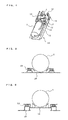
- Fig. 5 is a front view illustrating a mounting example of a conventional compressor
- Fig. 6 is a front view illustrating a mounting example of the compressor illustrated in Fig. 4 .
- Fig. 4 is a perspective view illustrating the compressor module of the vehicular air-conditioning apparatus according to the exemplary embodiment
- Fig. 5 is a front view illustrating a mounting example of a conventional compressor
- Fig. 6 is a front view illustrating a mounting example of the compressor illustrated in Fig. 4 .
- the above-mentioned compressor module 12 includes a sectionally groove-shaped support 13 having a flange on both ends; the compressor 2 disposed on the base plate of the support 13; the refrigerant gas-liquid separator 3, a check valve 14, a drying device 15, a solenoid valve 16, and a filter 17 that are pieces of auxiliary equipment; and the refrigerant pipes 11 connected to the compressor 2 and the auxiliary equipment by brazing.
- the solenoid valve 16 and other auxiliary equipment that need support are secured to a mounting member 18 provided to the support 13.
- the above-mentioned check valve 14 is a piece of auxiliary equipment for preventing backflow of the refrigerant
- the drying device 15 is a piece of auxiliary equipment for removing moisture content in the refrigerant.
- the solenoid valve 16 is a piece of auxiliary equipment for controlling the flow rate of the refrigerant
- the filter 17 is a piece of auxiliary equipment for filtering the refrigerant.
- the compressor 2 is secured to the vehicular-air-conditioner frame 1 interposed with rubber vibration insulators 25 therebetween.
- a sound amplification phenomenon has been encountered since the frame 1 functions as a speaker with the propagation of the sound generated by the compressor 2 to the base plate 26.
- Fig. 6 in the exemplary embodiment, since it will be possible to remove the base plate under the support 13 by interposing the support 13 of the compressor module 12 and the rubber vibration insulators 25 between the compressor 2 and the vehicular-air-conditioner frame 1, vibration propagation to the base plate 26 can be suppressed and sound can be released to the space so as not to be amplified; hence, noise reduction can be achieved.
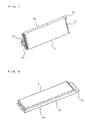
- FIG. 7 is a perspective view illustrating the indoor heat exchanger module of the vehicular air-conditioning apparatus according to the exemplary embodiment
- Fig. 8 is a perspective view illustrating the outdoor heat exchanger module of the vehicular air-conditioning apparatus according to the exemplary embodiment.
- an indoor heat exchanger module 19 includes the indoor heat exchanger 4, the solenoid valve 16 for controlling the capacity of the refrigerant, a distributor 23 for distributing the refrigerant, a capillary tube (not shown) for expanding the refrigerant, sheet metal members 21 provided on both ends of the indoor heat exchanger 4 in the longitudinal direction, and an air flow partition plate 22 provided on one lateral side of the indoor heat exchanger 4 in the width direction.
- an outdoor heat exchanger module 20 includes the outdoor heat exchanger 5, the sheet metal members 21 provided on both ends of the outdoor heat exchanger 5 in the longitudinal direction, and the air flow partition plate 22 provided on one lateral side of the outdoor heat exchanger 5 in the width direction.
- the above-mentioned sheet metal members 21 are parts for mounting the indoor heat exchanger 4 and outdoor heat exchanger 5 on the frame 1. Work on the production line can be reduced and productivity can be improved by attaching the sheet metal members 21 to the indoor heat exchanger 4 and outdoor heat exchanger 5 in advance.
- the air flow partition plate 22 is a member for preventing the air flow that has passed through the respective one of the heat exchangers 4 and 5 from passing through the heat exchanger again.
- FIG. 9 is a perspective view illustrating a refrigeration cycle module of the vehicular air-conditioning apparatus according to the exemplary embodiment
- Fig. 10 is a perspective view illustrating a state of the refrigeration cycle module of Fig. 9 before being mounted into a vehicular-air-conditioner frame
- Fig. 11 is a perspective view illustrating an explanatory configuration of a partition plate with respect to a refrigerant pipe when the refrigeration cycle module of Fig. 9 is mounted into the vehicular-air-conditioner frame.
- a refrigeration cycle module 24 is configured by connecting the compressor module 12, the indoor heat exchanger module 19, and the outdoor heat exchanger module 20 illustrated in Figs. 4 , 7, and 8 with the refrigerant pipes 11.
- the compressor module 12, the indoor heat exchanger module 19, the outdoor heat exchanger module 20, and the refrigeration cycle module 24, which is configured by combining these modules 12, 19, and 20, are assembled off the production line as described above.
- the refrigeration cycle modules 24 are mounted into the vehicular-air-conditioner frame 1 on the production line after the indoor fan 6, the outdoor fan 7, and other components have been mounted thereto. It will be possible to simultaneously carry out assembling on the production line and assembling of the refrigeration cycle module 24 and, thus, to improve productivity.
- each refrigeration cycle module 24 is mounted into the vehicular-air-conditioner frame 1, although the refrigerant pipe 11 extends over the partition plate 10 of the vehicular-air-conditioner frame 1, since a U-shaped notch 10a is provided in the upper portion of the partition plate 10 as shown in Fig. 11 , it will be possible to mount the refrigeration cycle module 24 into the vehicular-air-conditioner frame 1 by receiving the refrigerant pipe 11 into the notch 10a from above the notch. Thereafter, the notch 10a is closed with a closing plate 10b and the gap of the notch 10a is further filled with putty such that air-tightness between the indoor compartment 8 and the outdoor compartment is maintained.
- the compressor module 12, the indoor heat exchanger module 19, and the outdoor heat exchanger module 20 are assembled off the production line, as well as the refrigeration cycle module 24 by connecting these modules 12, 19, and 20 by refrigerant pipes 11. Accordingly, scarcely any brazing work of the refrigerant pipes 11 is required on the production line; hence, work is facilitated, quality improvement is enabled, and productivity can be substantially improved.
- the refrigeration cycle module 24 is assembled with each of the modules 12, 19, and 20, the refrigeration cycle module 24 may not be assembled. That is, workability, quality, and productivity can be improved by assembling only the compressor module 12, the indoor heat exchanger module 19, and the outdoor heat exchanger 20 off the production line.
- each of the modules 12, 19, and 20 is mounted on the vehicular-air-conditioner frame 1 with the completion of the arrangement and brazing of the components of each module.
- brazing on the production line can be reduced to three points at the fewest.
- the refrigerant pipe 11 is received into the U-shaped notch 10a provided in the upper portion of the partition plate 10 of the vehicular-air-conditioner frame 1 from above the notch 10a when the refrigeration cycle module 24 is mounted into the vehicular-air-conditioner frame 1; however, the invention is not limited to this.
- the invention is not limited to this.
- the depth of the cutaway of the U-shaped notch 10a provided in the upper portion of the partition plate 10 can be made shallow.
- the notch 10a is closed with a closing plate 10b and the gap of the notch 10a is further filled with putty such that air-tightness between the indoor compartment 8 and the outdoor compartment 9 is maintained.
Landscapes
- Engineering & Computer Science (AREA)
- Mechanical Engineering (AREA)
- Physics & Mathematics (AREA)
- Thermal Sciences (AREA)
- Air-Conditioning For Vehicles (AREA)
Abstract
Description
- The present invention relates to an assembling method of a vehicular air-conditioning apparatus mounted on, for example, a roof of a railroad vehicle.
- As conventional vehicular air-conditioning apparatuses, there exists, for example, one that disposes a compressor in the middle portion of a casing of an air-conditioning apparatus in the length direction of the vehicle, disposes an indoor fan on both sides of the compressor, and further disposes an indoor heat exchanger on both sides of each indoor fan, as well as disposing an outdoor fan on both ends of the casing in the length direction of the vehicle. (For example, see
Patent Literature 1.) -
- Patent Literature 1:
- Japanese Unexamined Patent Application Publication
JP-A-61-232 917 page 2,Fig. 1 ) - Incidentally, as regards vehicular air-conditioning apparatuses, a compressor, an indoor heat exchanger, an outdoor heat exchanger, which are main equipment of a refrigeration cycle, a check valve, a solenoid valve, and the like, which are auxiliary equipment, are arranged and fixed to a vehicular-air-conditioner frame and are each brazed to a refrigerant pipe on a production line.
With this assembling method, since brazing is carried out in an unnatural body position depending on the brazing point, there has been risk of adverse effect on quality. Further, since the above-described work is all carried out on a production line, there exists a need to improve productivity. - The invention is directed to solve the above-described problems and an object thereof is to reduce brazing work on the production line and to provide an assembling method of a vehicular air-conditioning apparatus capable of improving quality and increasing productivity.
- An assembling method of a vehicular air-conditioning apparatus according to the invention including various equipment, which is required for air-conditioning a vehicle, mounted in a vehicular-air-conditioner frame on a production line includes the steps of modularizing a refrigerant cycle including at least a compressor, an indoor heat exchanger, and an outdoor heat exchanger, among the various equipment, that are connected with refrigerant pipes by assembling the refrigerant cycle off the production line; and incorporating the refrigerant cycle into assembly work on the production line as a refrigerant cycle module.
- According to the invention, a refrigeration cycle including at least a compressor, an indoor heat exchanger, and an outdoor heat exchanger that are connected with refrigerant pipes is modularized by assembling them off a production line. The refrigeration cycle is incorporated into an assembly work on the production line as a refrigerant cycle module.
Accordingly, there is no need for brazing work of the refrigerant pipes on the production line; hence, work is facilitated, quality improvement is enabled, and productivity can be substantially improved. -
- Fig. 1
- is a plan view illustrating a vehicular air-conditioning apparatus according to an exemplary embodiment seen from above.
- Fig. 2
- is a block diagram illustrating an outline of a refrigeration cycle of the vehicular air-conditioning apparatus according to the exemplary embodiment.
- Fig. 3
- is a flowchart illustrating an assembling method of the vehicular air-conditioning apparatus according to the exemplary embodiment.
- Fig. 4
- is a perspective view illustrating a compressor module of the vehicular air-conditioning apparatus according to the exemplary embodiment.
- Fig. 5
- is a front view illustrating a mounting example of a conventional compressor.
- Fig. 6
- is a front view illustrating a mounting example of the compressor illustrated in
Fig. 4 . - Fig. 7
- is a perspective view illustrating an indoor heat exchanger module of the vehicular air-conditioning apparatus according to the exemplary embodiment.
- Fig. 8
- is a perspective view illustrating an outdoor heat exchanger module of the vehicular air-conditioning apparatus according to the exemplary embodiment.
- Fig. 9
- is a perspective view illustrating a refrigeration cycle module of the vehicular air-conditioning apparatus according to the exemplary embodiment.
- Fig. 10
- is a perspective view illustrating a state of the refrigeration cycle module of
Fig. 9 before being mounted into a vehicular-air-conditioner frame. - Fig. 11
- is a perspective view illustrating an explanatory configuration of a partition plate with respect to a refrigerant pipe when the refrigeration cycle module of
Fig. 9 is mounted into the vehicular-air-conditioner frame. - Fig. 12
- is a perspective view illustrating a modification of
Fig. 9 . -
Fig. 1 is a plan view illustrating a vehicular air-conditioning apparatus according to an exemplary embodiment seen from above, andFig. 2 is a block diagram illustrating an outline of a refrigeration cycle of the vehicular air-conditioning apparatus according to the exemplary embodiment.
The vehicular air-conditioning apparatus according to the exemplary embodiment is mounted on, for example, a roof of a railroad vehicle (hereinafter, referred to as a "vehicle"). As shown inFig. 1 , the vehicular air-conditioning apparatus includes a rectangular vehicular-air-conditioner frame 1, apartition plate 10 forming an indoor compartment 8 and anoutdoor compartment 9 by partitioning the vehicular-air-conditioner frame 1 in the length direction of the vehicle, an indoor fan 6 mounted on the center line of the indoor compartment 8 in the length direction of the vehicle.
The apparatus further includes:indoor heat exchangers 4 secured on both sides of the indoor fan 6, anoutdoor fan 7 mounted on the center line of theoutdoor compartment 9 in the length direction of the vehicle,compressors 2 and refrigerant gas-liquid separators 3 that are provided on both sides relative to the center line, andoutdoor heat exchangers 5 secured on both sides of theoutdoor fan 7. - As shown in
Fig. 2 , a refrigeration cycle of the vehicular air-conditioning apparatus is configured by interconnecting thecompressor 2 and the refrigerant gas-liquid separator 3, the refrigerant gas-liquid separator 3 and theindoor heat exchanger 4, and theindoor heat exchanger 4 and theoutdoor heat exchanger 5, by means ofrefrigerant pipes 11. - An assembling method of the above-described vehicular air-conditioning apparatus will now be described.
Fig. 3 is a flowchart illustrating an assembling method of the vehicular air-conditioning apparatus according to the exemplary embodiment.
Regarding the assembling of the vehicular air-conditioning apparatus, a refrigeration cycle including a compressor module, an outdoor heat exchanger module, and an indoor heat exchanger module assembled and each connected withrefrigerant pipes 11 off the production line is modularized (hereinafter, referred to as a "refrigeration cycle module").
Then, the assembling of the vehicular air-conditioning apparatus is completed by arranging the refrigeration cycle module, on the production line, into the vehicular-air-conditioner frame 1 mounted with the indoor fan 6 and theoutdoor fan 7, and by installing and performing wiring work to the refrigeration cycle module. - With such an assembling of the refrigeration cycle module off the production line, scarcely any brazing work of the
refrigerant pipes 11 is required on the production line. Accordingly, work is facilitated, and it is possible to improve quality. Further, it is possible to carry out assembling of the refrigeration cycle module and the assembling of other devices concurrently. Furthermore, since it is possible to carry out vacuum drawing of and charging of the refrigerant to the components of the refrigeration cycle, productivity can be improved substantially. - The assembling of the compressor module will be described subsequently.
Fig. 4 is a perspective view illustrating the compressor module of the vehicular air-conditioning apparatus according to the exemplary embodiment,Fig. 5 is a front view illustrating a mounting example of a conventional compressor, andFig. 6 is a front view illustrating a mounting example of the compressor illustrated inFig. 4 .
As shown inFig. 4 , the above-mentionedcompressor module 12 includes a sectionally groove-shaped support 13 having a flange on both ends; thecompressor 2 disposed on the base plate of thesupport 13; the refrigerant gas-liquid separator 3, acheck valve 14, adrying device 15, asolenoid valve 16, and afilter 17 that are pieces of auxiliary equipment; and therefrigerant pipes 11 connected to thecompressor 2 and the auxiliary equipment by brazing. Thesolenoid valve 16 and other auxiliary equipment that need support are secured to amounting member 18 provided to thesupport 13.
The above-mentionedcheck valve 14 is a piece of auxiliary equipment for preventing backflow of the refrigerant, and thedrying device 15 is a piece of auxiliary equipment for removing moisture content in the refrigerant. Further, thesolenoid valve 16 is a piece of auxiliary equipment for controlling the flow rate of the refrigerant, and thefilter 17 is a piece of auxiliary equipment for filtering the refrigerant. - Conventionally, as shown in
Fig. 5 , thecompressor 2 is secured to the vehicular-air-conditioner frame 1 interposed withrubber vibration insulators 25 therebetween. With this structure, a sound amplification phenomenon has been encountered since theframe 1 functions as a speaker with the propagation of the sound generated by thecompressor 2 to thebase plate 26.
Accordingly, as shown inFig. 6 , in the exemplary embodiment, since it will be possible to remove the base plate under thesupport 13 by interposing thesupport 13 of thecompressor module 12 and therubber vibration insulators 25 between thecompressor 2 and the vehicular-air-conditioner frame 1, vibration propagation to thebase plate 26 can be suppressed and sound can be released to the space so as not to be amplified; hence, noise reduction can be achieved. - Assembling of the indoor heat exchanger module and the outdoor heat exchanger module will be described next.
Fig. 7 is a perspective view illustrating the indoor heat exchanger module of the vehicular air-conditioning apparatus according to the exemplary embodiment, andFig. 8 is a perspective view illustrating the outdoor heat exchanger module of the vehicular air-conditioning apparatus according to the exemplary embodiment. - As shown in
Fig. 7 , an indoorheat exchanger module 19 includes theindoor heat exchanger 4, thesolenoid valve 16 for controlling the capacity of the refrigerant, adistributor 23 for distributing the refrigerant, a capillary tube (not shown) for expanding the refrigerant,sheet metal members 21 provided on both ends of theindoor heat exchanger 4 in the longitudinal direction, and an airflow partition plate 22 provided on one lateral side of theindoor heat exchanger 4 in the width direction. - As shown in
Fig. 8 , an outdoorheat exchanger module 20 includes theoutdoor heat exchanger 5, thesheet metal members 21 provided on both ends of theoutdoor heat exchanger 5 in the longitudinal direction, and the airflow partition plate 22 provided on one lateral side of theoutdoor heat exchanger 5 in the width direction.
The above-mentionedsheet metal members 21 are parts for mounting theindoor heat exchanger 4 andoutdoor heat exchanger 5 on theframe 1. Work on the production line can be reduced and productivity can be improved by attaching thesheet metal members 21 to theindoor heat exchanger 4 andoutdoor heat exchanger 5 in advance.
The airflow partition plate 22 is a member for preventing the air flow that has passed through the respective one of theheat exchangers - Next, a detailed description will be given of the assembling of the refrigeration cycle module and the mounting of the refrigeration cycle module.
Fig. 9 is a perspective view illustrating a refrigeration cycle module of the vehicular air-conditioning apparatus according to the exemplary embodiment,Fig. 10 is a perspective view illustrating a state of the refrigeration cycle module ofFig. 9 before being mounted into a vehicular-air-conditioner frame, andFig. 11 is a perspective view illustrating an explanatory configuration of a partition plate with respect to a refrigerant pipe when the refrigeration cycle module ofFig. 9 is mounted into the vehicular-air-conditioner frame. - A
refrigeration cycle module 24 is configured by connecting thecompressor module 12, the indoorheat exchanger module 19, and the outdoorheat exchanger module 20 illustrated inFigs. 4 ,7, and 8 with therefrigerant pipes 11. Thecompressor module 12, the indoorheat exchanger module 19, the outdoorheat exchanger module 20, and therefrigeration cycle module 24, which is configured by combining thesemodules - As shown in
Fig. 10 , therefrigeration cycle modules 24 are mounted into the vehicular-air-conditioner frame 1 on the production line after the indoor fan 6, theoutdoor fan 7, and other components have been mounted thereto. It will be possible to simultaneously carry out assembling on the production line and assembling of therefrigeration cycle module 24 and, thus, to improve productivity. - When each
refrigeration cycle module 24 is mounted into the vehicular-air-conditioner frame 1, although therefrigerant pipe 11 extends over thepartition plate 10 of the vehicular-air-conditioner frame 1, since aU-shaped notch 10a is provided in the upper portion of thepartition plate 10 as shown inFig. 11 , it will be possible to mount therefrigeration cycle module 24 into the vehicular-air-conditioner frame 1 by receiving therefrigerant pipe 11 into thenotch 10a from above the notch.
Thereafter, thenotch 10a is closed with aclosing plate 10b and the gap of thenotch 10a is further filled with putty such that air-tightness between the indoor compartment 8 and the outdoor compartment is maintained. - As described above, in the exemplary embodiment, the
compressor module 12, the indoorheat exchanger module 19, and the outdoorheat exchanger module 20 are assembled off the production line, as well as therefrigeration cycle module 24 by connecting thesemodules refrigerant pipes 11.
Accordingly, scarcely any brazing work of therefrigerant pipes 11 is required on the production line; hence, work is facilitated, quality improvement is enabled, and productivity can be substantially improved. - Further, by carrying out assembling of each of the
modules refrigeration cycle module 24 off the production line, it will be possible to carry out vacuum drawing of and charging of the refrigerant to the refrigeration cycle and to carry out refrigerant leakage check and the like off the production line. Accordingly, it will be possible to substantially reduce work time on the production line. - Note that although in the exemplary embodiment, the
refrigeration cycle module 24 is assembled with each of themodules refrigeration cycle module 24 may not be assembled. That is, workability, quality, and productivity can be improved by assembling only thecompressor module 12, the indoorheat exchanger module 19, and theoutdoor heat exchanger 20 off the production line.
In this case, each of themodules conditioner frame 1 with the completion of the arrangement and brazing of the components of each module. Here, other than being able to dispense with thenotch 10a of thepartition plate 10, brazing on the production line can be reduced to three points at the fewest. - Further, the same advantageous effects can be obtained by assembling only one of the
compressor module 12, indoorheat exchanger module 19, and the outdoorheat exchanger module 20, or two of the modules. - Furthermore, in the exemplary embodiment, the
refrigerant pipe 11 is received into theU-shaped notch 10a provided in the upper portion of thepartition plate 10 of the vehicular-air-conditioner frame 1 from above thenotch 10a when therefrigeration cycle module 24 is mounted into the vehicular-air-conditioner frame 1; however, the invention is not limited to this.
For example, as shown inFig. 12 , by bending therefrigerant pipe 11 into an inverted U-shape in advance, the depth of the cutaway of theU-shaped notch 10a provided in the upper portion of thepartition plate 10 can be made shallow. Moreover, stress exerted on therefrigerant pipe 11, which is disposed between thecompressor module 12 being a vibration portion and the indoor and outdoorheat exchanger modules
Note that in the above case as well, thenotch 10a is closed with aclosing plate 10b and the gap of thenotch 10a is further filled with putty such that air-tightness between the indoor compartment 8 and theoutdoor compartment 9 is maintained. - Additionally, although the description is given above of an assembling method of a vehicular air-conditioning apparatus that is mounted on a roof of a vehicle, the invention is not limited to this, and, for example, the method may be applied to a vehicular air-conditioning apparatus disposed on a floor, inside a floor, or under a floor of a vehicle.
-
List of Reference Signs 1 vehicular-air- conditioner frame 2 compressor 3 refrigerant gas- liquid separator 4 indoor heat exchanger 5 outdoor heat exchanger 6 indoor fan 7 outdoor fan 8 indoor compartment 9 outdoor compartment 10 partition plate 10a notch 10b closing plate 11 refrigerant pipe 12 compressor module 13 support 14 check valve 15 drying device 16 solenoid valve 17 filter 18 mounting member 19 indoor heat exchanger module 20 outdoor heat exchanger module 21 sheet metal member 22 air flow partition plate 23 distributor 24 refrigeration cycle module 25 rubber vibration insulator 26 base plate
Claims (9)
- An assembling method of a vehicular air-conditioning apparatus including various equipment, which is required for air-conditioning a vehicle, mounted in a vehicular-air-conditioner frame on a production line, the assembling method of the vehicular air-conditioning apparatus comprising the steps of:- modularizing a refrigerant cycle including at least a compressor, an indoor heat exchanger, and an outdoor heat exchanger, among the various equipment, that are connected with refrigerant pipes by assembling the refrigerant cycle off the production line; and- incorporating the modularized refrigerant cycle into assembly work on the production line as a refrigerant cycle module.
- The assembling method of the vehicular air-conditioning apparatus of claim 1,
further comprising the steps of:- providing a U-shaped notch in an upper portion of a partition plate provided in a substantially middle portion of the frame; and- receiving a refrigerant pipe of the refrigeration cycle module into the notch from above the notch when mounting the refrigerant cycle module into the frame. - The assembling method of the vehicular air-conditioning apparatus of claim 2,
further comprising the step of bending a portion of the refrigerant pipe that extends over the notch into an inverted U-shape. - The assembling method of the vehicular air-conditioning apparatus of any one of claims 1 to 3,
further comprising the step of modularizing the compressor and auxiliary equipment of the compressor as a single component of the refrigeration cycle module by combining the compressor and the auxiliary equipment off the production line. - The assembling method of the vehicular air-conditioning apparatus of any one of claims 1 to 4,
further comprising the step of modularizing the indoor heat exchanger and parts required in the indoor heat exchanger as a single component of the refrigeration cycle module by combining the indoor heat exchanger and the parts off the production line. - The assembling method of the vehicular air-conditioning apparatus of any one of claims 1 to 5,
further comprising the step of modularizing the outdoor heat exchanger and parts required in the outdoor heat exchanger as a single component of the refrigeration cycle module by combining the outdoor heat exchanger and the parts off the production line. - An assembling method of a vehicular air-conditioning apparatus including various equipment, which is required for air-conditioning a vehicle, mounted in a vehicular-air-conditioner frame on a production line, the assembling method of the vehicular air-conditioning apparatus comprising the steps of:- modularizing the compressor and auxiliary equipment of the compressor, among the various equipment, by combining the compressor and the auxiliary equipment off the production line; and- incorporating the compressor and the auxiliary equipment, which has been modularized, into assembly work on the production line as a compressor module.
- The assembling method of the vehicular air-conditioning apparatus of claim 7,
further comprising the steps of:- modularizing the indoor heat exchanger and parts required in the indoor heat exchanger, among the various equipment, by combining the indoor heat exchanger and the parts off the production line; and- incorporating the indoor heat exchanger and the parts, which has been modularized, into assembly work on the production line as an indoor heat exchanger module. - The assembling method of the vehicular air-conditioning apparatus of claim 7 or 8,
further comprising the steps of:- modularizing the outdoor heat exchanger and parts required in the outdoor heat exchanger, among the various equipment, by combining the outdoor heat exchanger and the parts off the production line; and- incorporating the outdoor heat exchanger and the parts, which has been modularized, into assembly work on the production line as an outdoor heat exchanger module.
Priority Applications (1)
| Application Number | Priority Date | Filing Date | Title |
|---|---|---|---|
| EP19210939.5A EP3632724B1 (en) | 2010-08-30 | 2010-08-30 | Assembling method of vehicular air-conditioning apparatus |
Applications Claiming Priority (1)
| Application Number | Priority Date | Filing Date | Title |
|---|---|---|---|
| PCT/JP2010/005315 WO2012029086A1 (en) | 2010-08-30 | 2010-08-30 | Method of assembling vehicular air conditioning device |
Related Child Applications (2)
| Application Number | Title | Priority Date | Filing Date |
|---|---|---|---|
| EP19210939.5A Division-Into EP3632724B1 (en) | 2010-08-30 | 2010-08-30 | Assembling method of vehicular air-conditioning apparatus |
| EP19210939.5A Division EP3632724B1 (en) | 2010-08-30 | 2010-08-30 | Assembling method of vehicular air-conditioning apparatus |
Publications (3)
| Publication Number | Publication Date |
|---|---|
| EP2612776A1 true EP2612776A1 (en) | 2013-07-10 |
| EP2612776A4 EP2612776A4 (en) | 2016-03-23 |
| EP2612776B1 EP2612776B1 (en) | 2020-04-15 |
Family
ID=45772232
Family Applications (2)
| Application Number | Title | Priority Date | Filing Date |
|---|---|---|---|
| EP19210939.5A Active EP3632724B1 (en) | 2010-08-30 | 2010-08-30 | Assembling method of vehicular air-conditioning apparatus |
| EP10856644.9A Active EP2612776B1 (en) | 2010-08-30 | 2010-08-30 | Method of assembling vehicular air conditioning device |
Family Applications Before (1)
| Application Number | Title | Priority Date | Filing Date |
|---|---|---|---|
| EP19210939.5A Active EP3632724B1 (en) | 2010-08-30 | 2010-08-30 | Assembling method of vehicular air-conditioning apparatus |
Country Status (5)
| Country | Link |
|---|---|
| US (1) | US9126293B2 (en) |
| EP (2) | EP3632724B1 (en) |
| JP (1) | JPWO2012029086A1 (en) |
| CN (1) | CN103079851B (en) |
| WO (1) | WO2012029086A1 (en) |
Cited By (2)
| Publication number | Priority date | Publication date | Assignee | Title |
|---|---|---|---|---|
| CN114749909A (en) * | 2022-03-22 | 2022-07-15 | 陕西泰德汽车空调有限公司 | Assembly and testing production line for parking air conditioners |
| CN115751467A (en) * | 2022-11-23 | 2023-03-07 | 珠海格力电器股份有限公司 | Modularized fan coil and air conditioner |
Families Citing this family (16)
| Publication number | Priority date | Publication date | Assignee | Title |
|---|---|---|---|---|
| CN103079854B (en) * | 2010-09-10 | 2016-03-09 | 三菱电机株式会社 | The update method of air conditioner for motor vehicle, air conditioner for motor vehicle |
| JP2014066372A (en) * | 2012-09-24 | 2014-04-17 | Panasonic Corp | Heat pump device for vehicle |
| JP6108857B2 (en) * | 2013-02-12 | 2017-04-05 | 三菱電機株式会社 | Air conditioner for vehicles |
| DE102014200623A1 (en) * | 2014-01-15 | 2015-07-16 | Mahle International Gmbh | Modular system for an evaporator device of a rooftop air conditioning system |
| JP6335106B2 (en) * | 2014-11-21 | 2018-05-30 | ヤンマー株式会社 | heat pump |
| US10780900B2 (en) | 2015-11-25 | 2020-09-22 | Mitsubishi Electric Corporation | Compressor module, air conditioning device for vehicle and compressor module manufacturing method |
| CN107635804B (en) * | 2015-11-27 | 2020-06-26 | 翰昂汽车零部件有限公司 | Cooling and heating module |
| US10391840B2 (en) * | 2016-07-15 | 2019-08-27 | TransArctic Canada, Inc. | Adaptable roof-mounted air conditioning system for vehicles |
| JP6305498B2 (en) * | 2016-11-21 | 2018-04-04 | 三菱電機株式会社 | Air conditioner for railway vehicles |
| US10815008B2 (en) | 2017-07-27 | 2020-10-27 | Bell Helicopter Textron Inc. | Lift propulsion module for a tiltrotor aircraft |
| JP6699685B2 (en) | 2018-03-30 | 2020-05-27 | ダイキン工業株式会社 | Refrigeration cycle equipment |
| JPWO2020202321A1 (en) * | 2019-03-29 | 2021-11-11 | 三菱電機株式会社 | Manufacturing method of air conditioner and air conditioner |
| IT201900016490A1 (en) * | 2019-09-17 | 2021-03-17 | Faiveley Transport Italia Spa | System for the generation of compressed air and for the conditioning of air, for a railway vehicle |
| CN111137102A (en) * | 2020-01-20 | 2020-05-12 | 郑州科林车用空调有限公司 | A modular design of passenger car overhead air conditioning unit |
| JP7200187B2 (en) * | 2020-09-28 | 2023-01-06 | 株式会社日立製作所 | Rail vehicle air conditioner |
| CN120038552B (en) * | 2025-03-27 | 2025-11-11 | 青岛海信日立空调系统有限公司 | Intelligent production line of air conditioner outdoor unit |
Family Cites Families (21)
| Publication number | Priority date | Publication date | Assignee | Title |
|---|---|---|---|---|
| JPS5867234A (en) | 1981-10-16 | 1983-04-21 | シチズン時計株式会社 | Pulse detecting circuit |
| JPS5867234U (en) * | 1981-10-31 | 1983-05-07 | 株式会社富士通ゼネラル | air conditioner |
| JPS58206417A (en) | 1982-05-24 | 1983-12-01 | Mitsubishi Electric Corp | Air conditioning device for car |
| JPS59149513U (en) | 1983-03-28 | 1984-10-05 | 株式会社東芝 | Vehicle air conditioner |
| JPS61232917A (en) | 1985-04-05 | 1986-10-17 | Toshiba Corp | Air-conditioning device for vehicle |
| US4675971A (en) * | 1985-12-03 | 1987-06-30 | Michigan Special Products, Inc. | Desiccant assembly for refrigeration circuit and method |
| JPH01172907U (en) | 1988-05-25 | 1989-12-07 | ||
| US5129144A (en) * | 1990-06-19 | 1992-07-14 | General Motors Corporation | Method of making a combination radiator and condenser apparatus for motor vehicle |
| US5603152A (en) * | 1994-12-19 | 1997-02-18 | General Motors Corporation | Method for manufacturing a two block line connector |
| JP3232934B2 (en) * | 1995-02-09 | 2001-11-26 | 松下電器産業株式会社 | Automotive air conditioners |
| JPH08318795A (en) * | 1995-05-24 | 1996-12-03 | Honda Motor Co Ltd | Wire harness structure in cockpit module |
| JP2000142394A (en) | 1998-11-12 | 2000-05-23 | Calsonic Corp | Air conditioner for rolling stock |
| WO2001068392A1 (en) * | 2000-03-13 | 2001-09-20 | Zexel Valeo Climate Control Corporation | Air conditioner for car |
| JP3973438B2 (en) * | 2002-02-06 | 2007-09-12 | 三洋電機株式会社 | Air conditioner |
| GB2387643B (en) * | 2002-04-16 | 2005-10-12 | Calsonic Kansei Uk Ltd | Vehicle air conditioning system |
| JP2004196282A (en) * | 2002-10-25 | 2004-07-15 | Denso Corp | Module structure of vehicle cockpit parts |
| US7819638B2 (en) * | 2004-09-30 | 2010-10-26 | Caterpillar Inc | Compressor mounting system |
| US7614242B1 (en) * | 2004-11-23 | 2009-11-10 | Carlos Quesada Saborio | Transport refrigeration system |
| CN101341039B (en) * | 2005-12-20 | 2011-04-20 | 开利公司 | Integrated transport refrigeration unit with limited heat transfer and quick mount housing |
| JP4899186B2 (en) | 2006-11-20 | 2012-03-21 | 株式会社ヴァレオジャパン | Automotive air conditioner |
| JP4325668B2 (en) | 2006-12-25 | 2009-09-02 | トヨタ自動車株式会社 | Air conditioner for vehicles |
-
2010
- 2010-08-30 EP EP19210939.5A patent/EP3632724B1/en active Active
- 2010-08-30 US US13/810,709 patent/US9126293B2/en active Active
- 2010-08-30 WO PCT/JP2010/005315 patent/WO2012029086A1/en not_active Ceased
- 2010-08-30 EP EP10856644.9A patent/EP2612776B1/en active Active
- 2010-08-30 JP JP2012531554A patent/JPWO2012029086A1/en active Pending
- 2010-08-30 CN CN201080068875.5A patent/CN103079851B/en active Active
Cited By (2)
| Publication number | Priority date | Publication date | Assignee | Title |
|---|---|---|---|---|
| CN114749909A (en) * | 2022-03-22 | 2022-07-15 | 陕西泰德汽车空调有限公司 | Assembly and testing production line for parking air conditioners |
| CN115751467A (en) * | 2022-11-23 | 2023-03-07 | 珠海格力电器股份有限公司 | Modularized fan coil and air conditioner |
Also Published As
| Publication number | Publication date |
|---|---|
| US20130112282A1 (en) | 2013-05-09 |
| EP2612776A4 (en) | 2016-03-23 |
| CN103079851A (en) | 2013-05-01 |
| US9126293B2 (en) | 2015-09-08 |
| JPWO2012029086A1 (en) | 2013-10-28 |
| CN103079851B (en) | 2016-06-22 |
| EP2612776B1 (en) | 2020-04-15 |
| EP3632724B1 (en) | 2021-05-19 |
| EP3632724A1 (en) | 2020-04-08 |
| WO2012029086A1 (en) | 2012-03-08 |
Similar Documents
| Publication | Publication Date | Title |
|---|---|---|
| EP2612776B1 (en) | Method of assembling vehicular air conditioning device | |
| US10962264B2 (en) | Heat source unit for refrigeration apparatus | |
| CN108349350B (en) | Compressor module, air conditioner for vehicle, and method for manufacturing compressor module | |
| CN204998303U (en) | Mounting structure of vehicle compressor unit spare and compressor | |
| US10267527B2 (en) | Outdoor unit for an air-conditioning device | |
| EP2058609A1 (en) | Air conditioner | |
| US20070261433A1 (en) | Component assembly for refrigerating cycle and refrigerating cycle having the same | |
| CA1113732A (en) | Combination process tube and vibration attenuator for a refrigeration circuit | |
| US20150337840A1 (en) | Compressor | |
| CN209840465U (en) | High-efficient pipe strap formula condenser convenient to installation | |
| EP3249310A1 (en) | Outdoor unit | |
| JP2005076924A (en) | Support structure for liquid reservoir and outdoor unit of air conditioner having the same | |
| WO2012073272A1 (en) | Air conditioner for vehicle | |
| JPH10205454A (en) | Compressor | |
| JP2017194227A (en) | Heat source unit | |
| CN206637752U (en) | Outdoor unit of air conditioner | |
| EP1460357A3 (en) | Wire-and-tube condenser for refrigeration appliances | |
| CN102767871B (en) | The band of electric-controlled box and binding structure thereof | |
| JP2000062448A (en) | Vehicle air conditioner | |
| EP3385627B1 (en) | Outdoor unit | |
| CN209512242U (en) | Vibration damper and air conditioning unit | |
| CN104728929B (en) | Air-conditioner set | |
| US20050201872A1 (en) | Pipe support for compressor subassembly | |
| JP6272110B2 (en) | Air conditioner for vehicles | |
| EP3764003A1 (en) | Refrigeration cycle device |
Legal Events
| Date | Code | Title | Description |
|---|---|---|---|
| PUAI | Public reference made under article 153(3) epc to a published international application that has entered the european phase |
Free format text: ORIGINAL CODE: 0009012 |
|
| 17P | Request for examination filed |
Effective date: 20130219 |
|
| AK | Designated contracting states |
Kind code of ref document: A1 Designated state(s): AL AT BE BG CH CY CZ DE DK EE ES FI FR GB GR HR HU IE IS IT LI LT LU LV MC MK MT NL NO PL PT RO SE SI SK SM TR |
|
| DAX | Request for extension of the european patent (deleted) | ||
| RA4 | Supplementary search report drawn up and despatched (corrected) |
Effective date: 20160218 |
|
| RIC1 | Information provided on ipc code assigned before grant |
Ipc: B60H 1/32 20060101ALI20160212BHEP Ipc: B61D 27/00 20060101ALI20160212BHEP Ipc: B60H 1/00 20060101AFI20160212BHEP Ipc: B23P 11/00 20060101ALI20160212BHEP |
|
| STAA | Information on the status of an ep patent application or granted ep patent |
Free format text: STATUS: EXAMINATION IS IN PROGRESS |
|
| 17Q | First examination report despatched |
Effective date: 20180213 |
|
| GRAP | Despatch of communication of intention to grant a patent |
Free format text: ORIGINAL CODE: EPIDOSNIGR1 |
|
| STAA | Information on the status of an ep patent application or granted ep patent |
Free format text: STATUS: GRANT OF PATENT IS INTENDED |
|
| INTG | Intention to grant announced |
Effective date: 20191210 |
|
| GRAS | Grant fee paid |
Free format text: ORIGINAL CODE: EPIDOSNIGR3 |
|
| GRAA | (expected) grant |
Free format text: ORIGINAL CODE: 0009210 |
|
| STAA | Information on the status of an ep patent application or granted ep patent |
Free format text: STATUS: THE PATENT HAS BEEN GRANTED |
|
| AK | Designated contracting states |
Kind code of ref document: B1 Designated state(s): AL AT BE BG CH CY CZ DE DK EE ES FI FR GB GR HR HU IE IS IT LI LT LU LV MC MK MT NL NO PL PT RO SE SI SK SM TR |
|
| REG | Reference to a national code |
Ref country code: CH Ref legal event code: EP Ref country code: GB Ref legal event code: FG4D |
|
| REG | Reference to a national code |
Ref country code: DE Ref legal event code: R096 Ref document number: 602010063954 Country of ref document: DE |
|
| REG | Reference to a national code |
Ref country code: IE Ref legal event code: FG4D |
|
| REG | Reference to a national code |
Ref country code: AT Ref legal event code: REF Ref document number: 1256848 Country of ref document: AT Kind code of ref document: T Effective date: 20200515 |
|
| REG | Reference to a national code |
Ref country code: NL Ref legal event code: MP Effective date: 20200415 |
|
| REG | Reference to a national code |
Ref country code: LT Ref legal event code: MG4D |
|
| PG25 | Lapsed in a contracting state [announced via postgrant information from national office to epo] |
Ref country code: SE Free format text: LAPSE BECAUSE OF FAILURE TO SUBMIT A TRANSLATION OF THE DESCRIPTION OR TO PAY THE FEE WITHIN THE PRESCRIBED TIME-LIMIT Effective date: 20200415 Ref country code: NL Free format text: LAPSE BECAUSE OF FAILURE TO SUBMIT A TRANSLATION OF THE DESCRIPTION OR TO PAY THE FEE WITHIN THE PRESCRIBED TIME-LIMIT Effective date: 20200415 Ref country code: LT Free format text: LAPSE BECAUSE OF FAILURE TO SUBMIT A TRANSLATION OF THE DESCRIPTION OR TO PAY THE FEE WITHIN THE PRESCRIBED TIME-LIMIT Effective date: 20200415 Ref country code: GR Free format text: LAPSE BECAUSE OF FAILURE TO SUBMIT A TRANSLATION OF THE DESCRIPTION OR TO PAY THE FEE WITHIN THE PRESCRIBED TIME-LIMIT Effective date: 20200716 Ref country code: NO Free format text: LAPSE BECAUSE OF FAILURE TO SUBMIT A TRANSLATION OF THE DESCRIPTION OR TO PAY THE FEE WITHIN THE PRESCRIBED TIME-LIMIT Effective date: 20200715 Ref country code: FI Free format text: LAPSE BECAUSE OF FAILURE TO SUBMIT A TRANSLATION OF THE DESCRIPTION OR TO PAY THE FEE WITHIN THE PRESCRIBED TIME-LIMIT Effective date: 20200415 Ref country code: IS Free format text: LAPSE BECAUSE OF FAILURE TO SUBMIT A TRANSLATION OF THE DESCRIPTION OR TO PAY THE FEE WITHIN THE PRESCRIBED TIME-LIMIT Effective date: 20200815 Ref country code: PT Free format text: LAPSE BECAUSE OF FAILURE TO SUBMIT A TRANSLATION OF THE DESCRIPTION OR TO PAY THE FEE WITHIN THE PRESCRIBED TIME-LIMIT Effective date: 20200817 |
|
| REG | Reference to a national code |
Ref country code: AT Ref legal event code: MK05 Ref document number: 1256848 Country of ref document: AT Kind code of ref document: T Effective date: 20200415 |
|
| PG25 | Lapsed in a contracting state [announced via postgrant information from national office to epo] |
Ref country code: LV Free format text: LAPSE BECAUSE OF FAILURE TO SUBMIT A TRANSLATION OF THE DESCRIPTION OR TO PAY THE FEE WITHIN THE PRESCRIBED TIME-LIMIT Effective date: 20200415 Ref country code: HR Free format text: LAPSE BECAUSE OF FAILURE TO SUBMIT A TRANSLATION OF THE DESCRIPTION OR TO PAY THE FEE WITHIN THE PRESCRIBED TIME-LIMIT Effective date: 20200415 Ref country code: BG Free format text: LAPSE BECAUSE OF FAILURE TO SUBMIT A TRANSLATION OF THE DESCRIPTION OR TO PAY THE FEE WITHIN THE PRESCRIBED TIME-LIMIT Effective date: 20200715 |
|
| PG25 | Lapsed in a contracting state [announced via postgrant information from national office to epo] |
Ref country code: AL Free format text: LAPSE BECAUSE OF FAILURE TO SUBMIT A TRANSLATION OF THE DESCRIPTION OR TO PAY THE FEE WITHIN THE PRESCRIBED TIME-LIMIT Effective date: 20200415 |
|
| REG | Reference to a national code |
Ref country code: DE Ref legal event code: R097 Ref document number: 602010063954 Country of ref document: DE |
|
| PG25 | Lapsed in a contracting state [announced via postgrant information from national office to epo] |
Ref country code: RO Free format text: LAPSE BECAUSE OF FAILURE TO SUBMIT A TRANSLATION OF THE DESCRIPTION OR TO PAY THE FEE WITHIN THE PRESCRIBED TIME-LIMIT Effective date: 20200415 Ref country code: CZ Free format text: LAPSE BECAUSE OF FAILURE TO SUBMIT A TRANSLATION OF THE DESCRIPTION OR TO PAY THE FEE WITHIN THE PRESCRIBED TIME-LIMIT Effective date: 20200415 Ref country code: DK Free format text: LAPSE BECAUSE OF FAILURE TO SUBMIT A TRANSLATION OF THE DESCRIPTION OR TO PAY THE FEE WITHIN THE PRESCRIBED TIME-LIMIT Effective date: 20200415 Ref country code: ES Free format text: LAPSE BECAUSE OF FAILURE TO SUBMIT A TRANSLATION OF THE DESCRIPTION OR TO PAY THE FEE WITHIN THE PRESCRIBED TIME-LIMIT Effective date: 20200415 Ref country code: SM Free format text: LAPSE BECAUSE OF FAILURE TO SUBMIT A TRANSLATION OF THE DESCRIPTION OR TO PAY THE FEE WITHIN THE PRESCRIBED TIME-LIMIT Effective date: 20200415 Ref country code: AT Free format text: LAPSE BECAUSE OF FAILURE TO SUBMIT A TRANSLATION OF THE DESCRIPTION OR TO PAY THE FEE WITHIN THE PRESCRIBED TIME-LIMIT Effective date: 20200415 Ref country code: EE Free format text: LAPSE BECAUSE OF FAILURE TO SUBMIT A TRANSLATION OF THE DESCRIPTION OR TO PAY THE FEE WITHIN THE PRESCRIBED TIME-LIMIT Effective date: 20200415 |
|
| PLBE | No opposition filed within time limit |
Free format text: ORIGINAL CODE: 0009261 |
|
| STAA | Information on the status of an ep patent application or granted ep patent |
Free format text: STATUS: NO OPPOSITION FILED WITHIN TIME LIMIT |
|
| PG25 | Lapsed in a contracting state [announced via postgrant information from national office to epo] |
Ref country code: PL Free format text: LAPSE BECAUSE OF FAILURE TO SUBMIT A TRANSLATION OF THE DESCRIPTION OR TO PAY THE FEE WITHIN THE PRESCRIBED TIME-LIMIT Effective date: 20200415 Ref country code: SK Free format text: LAPSE BECAUSE OF FAILURE TO SUBMIT A TRANSLATION OF THE DESCRIPTION OR TO PAY THE FEE WITHIN THE PRESCRIBED TIME-LIMIT Effective date: 20200415 |
|
| 26N | No opposition filed |
Effective date: 20210118 |
|
| PG25 | Lapsed in a contracting state [announced via postgrant information from national office to epo] |
Ref country code: MC Free format text: LAPSE BECAUSE OF FAILURE TO SUBMIT A TRANSLATION OF THE DESCRIPTION OR TO PAY THE FEE WITHIN THE PRESCRIBED TIME-LIMIT Effective date: 20200415 |
|
| REG | Reference to a national code |
Ref country code: CH Ref legal event code: PL |
|
| PG25 | Lapsed in a contracting state [announced via postgrant information from national office to epo] |
Ref country code: LI Free format text: LAPSE BECAUSE OF NON-PAYMENT OF DUE FEES Effective date: 20200831 Ref country code: CH Free format text: LAPSE BECAUSE OF NON-PAYMENT OF DUE FEES Effective date: 20200831 Ref country code: LU Free format text: LAPSE BECAUSE OF NON-PAYMENT OF DUE FEES Effective date: 20200830 |
|
| REG | Reference to a national code |
Ref country code: BE Ref legal event code: MM Effective date: 20200831 |
|
| PG25 | Lapsed in a contracting state [announced via postgrant information from national office to epo] |
Ref country code: SI Free format text: LAPSE BECAUSE OF FAILURE TO SUBMIT A TRANSLATION OF THE DESCRIPTION OR TO PAY THE FEE WITHIN THE PRESCRIBED TIME-LIMIT Effective date: 20200415 |
|
| PG25 | Lapsed in a contracting state [announced via postgrant information from national office to epo] |
Ref country code: BE Free format text: LAPSE BECAUSE OF NON-PAYMENT OF DUE FEES Effective date: 20200831 Ref country code: IE Free format text: LAPSE BECAUSE OF NON-PAYMENT OF DUE FEES Effective date: 20200830 |
|
| PG25 | Lapsed in a contracting state [announced via postgrant information from national office to epo] |
Ref country code: TR Free format text: LAPSE BECAUSE OF FAILURE TO SUBMIT A TRANSLATION OF THE DESCRIPTION OR TO PAY THE FEE WITHIN THE PRESCRIBED TIME-LIMIT Effective date: 20200415 Ref country code: MT Free format text: LAPSE BECAUSE OF FAILURE TO SUBMIT A TRANSLATION OF THE DESCRIPTION OR TO PAY THE FEE WITHIN THE PRESCRIBED TIME-LIMIT Effective date: 20200415 Ref country code: CY Free format text: LAPSE BECAUSE OF FAILURE TO SUBMIT A TRANSLATION OF THE DESCRIPTION OR TO PAY THE FEE WITHIN THE PRESCRIBED TIME-LIMIT Effective date: 20200415 |
|
| PG25 | Lapsed in a contracting state [announced via postgrant information from national office to epo] |
Ref country code: MK Free format text: LAPSE BECAUSE OF FAILURE TO SUBMIT A TRANSLATION OF THE DESCRIPTION OR TO PAY THE FEE WITHIN THE PRESCRIBED TIME-LIMIT Effective date: 20200415 |
|
| REG | Reference to a national code |
Ref country code: DE Ref legal event code: R084 Ref document number: 602010063954 Country of ref document: DE |
|
| REG | Reference to a national code |
Ref country code: GB Ref legal event code: 746 Effective date: 20221230 |
|
| P01 | Opt-out of the competence of the unified patent court (upc) registered |
Effective date: 20230512 |
|
| PGFP | Annual fee paid to national office [announced via postgrant information from national office to epo] |
Ref country code: DE Payment date: 20250702 Year of fee payment: 16 |
|
| PGFP | Annual fee paid to national office [announced via postgrant information from national office to epo] |
Ref country code: IT Payment date: 20250722 Year of fee payment: 16 |
|
| PGFP | Annual fee paid to national office [announced via postgrant information from national office to epo] |
Ref country code: GB Payment date: 20250703 Year of fee payment: 16 |
|
| PGFP | Annual fee paid to national office [announced via postgrant information from national office to epo] |
Ref country code: FR Payment date: 20250703 Year of fee payment: 16 |