EP2611983B1 - Polymer film for conditioning a drill pipe - Google Patents
Polymer film for conditioning a drill pipe Download PDFInfo
- Publication number
- EP2611983B1 EP2611983B1 EP11757228.9A EP11757228A EP2611983B1 EP 2611983 B1 EP2611983 B1 EP 2611983B1 EP 11757228 A EP11757228 A EP 11757228A EP 2611983 B1 EP2611983 B1 EP 2611983B1
- Authority
- EP
- European Patent Office
- Prior art keywords
- protector
- film
- tube
- assembly according
- sleeve
- Prior art date
- Legal status (The legal status is an assumption and is not a legal conclusion. Google has not performed a legal analysis and makes no representation as to the accuracy of the status listed.)
- Not-in-force
Links
Images


Classifications
-
- F—MECHANICAL ENGINEERING; LIGHTING; HEATING; WEAPONS; BLASTING
- F16—ENGINEERING ELEMENTS AND UNITS; GENERAL MEASURES FOR PRODUCING AND MAINTAINING EFFECTIVE FUNCTIONING OF MACHINES OR INSTALLATIONS; THERMAL INSULATION IN GENERAL
- F16L—PIPES; JOINTS OR FITTINGS FOR PIPES; SUPPORTS FOR PIPES, CABLES OR PROTECTIVE TUBING; MEANS FOR THERMAL INSULATION IN GENERAL
- F16L57/00—Protection of pipes or objects of similar shape against external or internal damage or wear
-
- B—PERFORMING OPERATIONS; TRANSPORTING
- B65—CONVEYING; PACKING; STORING; HANDLING THIN OR FILAMENTARY MATERIAL
- B65D—CONTAINERS FOR STORAGE OR TRANSPORT OF ARTICLES OR MATERIALS, e.g. BAGS, BARRELS, BOTTLES, BOXES, CANS, CARTONS, CRATES, DRUMS, JARS, TANKS, HOPPERS, FORWARDING CONTAINERS; ACCESSORIES, CLOSURES, OR FITTINGS THEREFOR; PACKAGING ELEMENTS; PACKAGES
- B65D59/00—Plugs, sleeves, caps, or like rigid or semi-rigid elements for protecting parts of articles or for bundling articles, e.g. protectors for screw-threads, end caps for tubes or for bundling rod-shaped articles
- B65D59/06—Caps
-
- E—FIXED CONSTRUCTIONS
- E21—EARTH DRILLING; MINING
- E21B—EARTH DRILLING, e.g. DEEP DRILLING; OBTAINING OIL, GAS, WATER, SOLUBLE OR MELTABLE MATERIALS OR A SLURRY OF MINERALS FROM WELLS
- E21B17/00—Drilling rods or pipes; Flexible drill strings; Kellies; Drill collars; Sucker rods; Cables; Casings; Tubings
- E21B17/006—Accessories for drilling pipes, e.g. cleaners
-
- F—MECHANICAL ENGINEERING; LIGHTING; HEATING; WEAPONS; BLASTING
- F16—ENGINEERING ELEMENTS AND UNITS; GENERAL MEASURES FOR PRODUCING AND MAINTAINING EFFECTIVE FUNCTIONING OF MACHINES OR INSTALLATIONS; THERMAL INSULATION IN GENERAL
- F16L—PIPES; JOINTS OR FITTINGS FOR PIPES; SUPPORTS FOR PIPES, CABLES OR PROTECTIVE TUBING; MEANS FOR THERMAL INSULATION IN GENERAL
- F16L57/00—Protection of pipes or objects of similar shape against external or internal damage or wear
- F16L57/005—Protection of pipes or objects of similar shape against external or internal damage or wear specially adapted for the ends of pipes
-
- Y—GENERAL TAGGING OF NEW TECHNOLOGICAL DEVELOPMENTS; GENERAL TAGGING OF CROSS-SECTIONAL TECHNOLOGIES SPANNING OVER SEVERAL SECTIONS OF THE IPC; TECHNICAL SUBJECTS COVERED BY FORMER USPC CROSS-REFERENCE ART COLLECTIONS [XRACs] AND DIGESTS
- Y10—TECHNICAL SUBJECTS COVERED BY FORMER USPC
- Y10T—TECHNICAL SUBJECTS COVERED BY FORMER US CLASSIFICATION
- Y10T29/00—Metal working
- Y10T29/49—Method of mechanical manufacture
- Y10T29/49826—Assembling or joining
Definitions
- the present invention relates to the field of conditioning of oil extraction tubes, and more particularly to the sealing means of the thread protectors disposed at the ends of these tubes.
- the oil extraction tubes are used for the drilling of wells, in order to reach important depths.
- These tubes have at each of their ends threads for connecting them to each other either directly or by means of intermediate elements.
- the threaded ends of the tubes are called male ends, while the threaded ends of the tubes are called female ends.
- a protector fitting on a male end of a tube is called a male protector (or Pin), and a protector fitting on a female end of a tube is qualified as a female protector (or box).
- Tubes having solid or permanent lubrication means in their threads have therefore been proposed, so as not to require thread lubrication operations prior to each use of the tubes, the tubes then being permanently lubricated as soon as they are manufactured.
- the oil extraction tubes then require protectors to protect their threaded ends, so that the thread and the lubricant is not damaged during storage and handling during the transportation of the tubes.
- API 5CT standard also called ISO 11960 defines more precisely the requirements that these protectors must meet.
- This improved protector can have several male or female variants, so as to adapt to different ends of tubes.
- the document US 6196270 a protector according to the preamble of claim 1.
- the document US 4662402 has a protector comprising a body provided with an elastomeric sheath, but not allowing a satisfactory assembly with an extraction tube.
- the protector is advantageously associated with a means ensuring the sealing of the connection between the protector and the tube.
- This means typically has particular properties, especially so as to ensure a sufficient seal without degrading the lubricant on the thread during its introduction and its removal.
- the present invention aims at providing a means for producing a tight connection between an oil extraction tube and a thread protector of such a tube.
- said film has a thickness of between 0.001 mm and 5 mm.
- said film is fixed to the protector by gluing or by means of a ring welded to said protector.
- the protector has a substantially frustoconical section having an inner wall, and the film is adhered to the inner wall of said protector.
- the film has a sliding coefficient of between 0.05 and 0.5.
- the film forms a sleeve having a length of between 15 and 30 cm, or such that the ratio of the length of the sleeve to the diameter of the extraction tube is between 0.5 and 10.
- the film forms a sleeve having a first end attached to the protector, and a second free end, said sleeve having on at least a portion of its length a rest diameter less than the outer diameter of the tube.
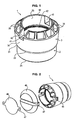
- the figure 1 shows an exemplary embodiment of a male protector 1 extraction tube.
- the connecting segment 2 has a proximal end 21 and a distal end 22, and has a substantially frustoconical shape whose diameter decreases from the proximal end 21 towards the distal end 22.
- the bumper segment 3 has a connecting end 31 and a free end 32, its connecting end 31 being in the extension of the distal end 22 of the connecting segment 2.
- the bumper segment 3 comprises an inner ring 33 and an outer ring 34, these two rings 33 and 34 being concentric and defining between them an internal space 35.
- the inner ring 33 as shown comprises a frustoconical portion in the extension of the distal end 22 of the connecting segment 2, and a portion having a hollow cylinder shape in the extension of this frustoconical portion, the diameter of this section. cylindrical substantially corresponding to the inner diameter of the tube on which the male protector is intended to be positioned.
- the inner ring 33 is thus typically offset radially with respect to the frustoconical connecting segment 2 and thus typically comprises a connecting wall 23, visible on the figure 5 which will be detailed below, this connecting wall 23 being disposed between the frustoconical portion and the cylindrical portion of the inner ring 33.
- the outer ring 34 has a frustoconical section, the diameter increases of the connecting end 31 to the free end 32 of the connecting segment 3, the maximum diameter of the outer ring 34 being greater than the maximum diameter of the connecting segment 2.
- the outer ring 34 thus typically has an angle of 5 ° with respect to the axis of the male protector 1.
- the male protector 1 illustrated has two grooves 40 extending along a diameter of the male protector 1, from the free end 32.
- These grooves 40 are adapted to allow to insert a tool for screwing and unscrewing the protector on a tube.
- These grooves 40 further have orifices 41 arranged on one of their walls, these orifices 41 being intended to allow the attachment of a substantially circular capsule obstructing the free end 32 of the male protector 1.
- the figure 2 presents the male protector 1 presented above, as well as two embodiments of such capsules 45 and 46.
- the capsules comprise projections 47 complementary to the orifices 41 of the male protector 1, so as to be held in position at its free end 32.
- the embodiment 45 of the capsule covers all of its free end 32, and has a diameter corresponding to the maximum diameter of the male protector 1.
- Embodiment 46 is content, for its part, to obstruct the opening defined by the inner ring 33, and therefore has a diameter substantially corresponding to the internal diameter of this inner ring 33.
- the male protector 1 comprises longitudinal ribs 36 connecting the inner ring 33 and the outer ring 34, and thus segmenting the inner space 35 between the inner ring 33 and the outer ring 34 in multiple compartments. .
- the male protector 1 comprises twelve longitudinal ribs 36, the sides of each of the grooves 40 are delimited by two ribs 36, and the remaining ribs 36 are distributed substantially uniformly between the inner ring 33 and the crown. external 34.
- the free end 32 of the male protector 1 is bevelled at substantially 45%, resulting in a narrowing of the diameter towards the free end 32.
- This inclination at 45% increases the resistance of the male protector 1 to shocks, and thus more effectively protect the tube on which it is intended to be mounted a protector having a free end 32 at right angles.
- the male protector 1 further comprises threads 42 disposed at the inner wall of the connecting segment 2, these threads 42 being adapted to cooperate with the threads of a tube on which said male protector 1 is intended to be assembled. These threads 42 form a male thread, are typically made by tapping, and are advantageously discontinuous.
- the threads 42 of the male protector 1 typically comprise one, two or three turns, other variants being of course possible.
- a reduced number of turns makes it possible to limit the impact on the lubricant of the threads of the tube that the male protector 1 is intended to protect, this number of turns, however, being chosen so as to ensure sufficient retention of the male protector 1 on the tube.
- the male protector 1 is made of polycarbonate by injection.
- the specific geometry of the protector 1 has important advantages for its production by injection. Indeed, all the walls of the protector 1 have a substantially equal thickness, including the walls of the bumper segment 3 due to the presence of the ribs 36.
- the protector 1 as described has a reduced cost of production compared to a similar overall shape protector, but the shock segment 3 would be "full".
- connections and ridges advantageously have fillets or rounds so that the protector 1 does not does not include sharp corners, which allows to promote the demolding. Furthermore, the fact of not understanding sharp angles avoids the risk of degradation of the film which will be described below.
- Polycarbonate is a very efficient material for the production of the protector 1, the injection of which is made possible because of the specific shape of the protector.
- the polycarbonate is a transparent material, which allows the user to directly control the state of the threads of the tube on which the protector 1 is positioned, without the need to remove the protector 1 to proceed to a such control.
- the protector 1 is advantageously subjected to a surface treatment, in order to carry out an ultraviolet and / or infrared filtering, such treatment being typically composed of a soaking and then a plasma treatment under the microwaves in the presence of 'ozone.
- the material of which the protector 1 is made typically polycarbonate, may be chosen to have such ultraviolet and / or infrared filtering characteristics.
- the solid lubricants used on tube threads can indeed be sensitive to ultraviolet and infrared, and must therefore be protected.
- the male protectors 1 proposed can effectively protect the threaded ends of an oil extraction tube, making a tight connection while allowing the various operations of handling and control of the tube, and maintaining a production cost reasonable because of their shape specifically adapted to the injection.
- the male protector 1 as shown on the figure 1 is typically associated with an elastomeric film 60.
- the elastomeric film is a monolayer urethane ester film, for example the film sold under the reference Vacfilm 430 by the company Richmond Aerovac.
- the film has a useful thickness typically between 0.001 mm and 5 mm, for example between 100 and 200 microns, typically of the order or equal to 100 or 200 microns.
- the elastomeric film is a tri-layer film of composition EPDM (ethylene propylene diene monomer) on the outer layers, and EMA (ethylene methyl acrylate) on the inner layer
- EPDM ethylene propylene diene monomer
- EMA ethylene methyl acrylate
- the film has a useful thickness typically between 0.001 mm and 5 mm, for example of the order or equal to 200 microns.
- a slip additive for example the Erucamide molecule in a proportion of between 0.1 and 50% of the mass of the EPDM is typically added to the EPDM in order to reduce its adhesion, for example to have a slip coefficient included between 0.05 and 0.80.
- linear or low density polymers are used, for example, which make it possible to obtain a flexible film.
- the semi-crystalline polymers of low density have a larger amorphous phase, and thus allow a more controlled additivation because the charges are housed in the amorphous phase.
- the elastomeric film is a two-layer film composed of a first layer of elastane, for example material sold under the name Lycra (trademark of a third party), or a mixture of elastane and Polyhexamethylene adipamide, sold under the name nylon (trademark registered by a third party), for example in proportions of 20% / 80%, and a second urethane ester layer, for example the film marketed under the reference Vacfilm 430 by the Richmond Aerovac company.
- a first layer of elastane for example material sold under the name Lycra (trademark of a third party), or a mixture of elastane and Polyhexamethylene adipamide, sold under the name nylon (trademark registered by a third party), for example in proportions of 20% / 80%
- a second urethane ester layer for example the film marketed under the reference Vacfilm 430 by the Richmond Aerovac company.
- the bi-layer film thus formed has a useful thickness typically between 0.001 mm and 5 mm, for example of the order or equal to 1050 microns, corresponding to 1000 microns of the first layer of Lycra and 50 microns of the second layer.
- the elastomeric film 60 is shaped to form a tube or sleeve, and is attached to the male protector 1.
- This attachment may for example be made by bonding the film 60 directly to the protector 1, or by welding or embedding a ring to the protector 1 so as to grip the film 60.
- the adhesive is chosen so that the fixing of the polymer film 60 on the male protector 1 is final, that is to say that the polymer film 60 can not be removed from the male protector without degrading, unlike a removable attachment.
- the elastomeric film 60 can be fixed to the protector 1 by means of a ring 70 welded to the protector 1.
- the figure 4 schematically illustrates a sectional view of an assembly consisting of a protector 1 and an elastomeric film 60 fixed to the protector by means of such a ring 70.
- the elastomeric film 60 is thus fixed permanently on the protector 1.
- the film 60 may be prefixed to the ring 70 prior to its setting on the protector 1, so as to facilitate its implementation.
- the sleeve made of elastomeric film 60 typically has a length of between 15 and 30 cm, or for example a length such that the ratio of the length of the sleeve to the diameter of the extraction tube is between 0.5 and 10.
- the elastomeric film 60 is typically folded around the proximal end 21 so as to cover the outer wall of the male protector 1, as shown in FIG. figure 5 .
- the sleeve typically has a first end attached to the protector 1, and a second free end.
- the elastomeric film 60 is sized and has stretching properties so that the sleeve has over at least a part of its length, a diameter at rest (when not stretched) lower the outer diameter of the tube 4, the sleeve being stretchable for its introduction and its folding on the protector 1.
- the male protector 1 is then placed in position on a petroleum extraction tube, typically by screwing it to one end of the tube. During this installation, the elastomeric film comes to slide on the threading the tube, without degrading the lubricant due to the properties of the elastomeric film 60, including its adhesion and sliding coefficient.
- the part of the elastomeric film 60 which was folded on the outer face of the male protector 1 is then unwound or folded so as to cover a portion of the tube, typically a length of between 15 and 30 cm.
- the sleeve then grips the tube 4 due to its diameter less than the external diameter of the tube 4.
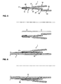
- the figure 6 shows a block diagram of a male protector 1 placed in position on a threaded tube 4, the elastomeric film 60 being unwound on a part of the threaded tube 4.
- the portion of the elastomeric film 60 which was folded over the outer face of the male protector 1 is then separated from the portion of the elastomeric film 60 fixed to the protector 1, typically by tearing or cutting.
- This separation of the elastomeric film 60 is advantageously carried out substantially at the proximal end 22 of the connecting segment 2 of the protector 1. Once this separation has been performed, the portion of the elastomeric film 60 fixed to the protector 1 retracts on the threaded tube 4 because of its diameter smaller than the external diameter of the tube 4.
- the elastomeric film 60 then advantageously has one or more pre-cuts, in order to facilitate its separation.
- FIG. 7 and 8 show a block diagram of a male protector 1 placed in position on a threaded tube 4, the elastomeric film 60 being cut or torn at the proximal end 22 of the connecting segment 2 of the protector 1.
- the figure 7 presents the tearing or cutting of the elastomeric film 60
- the figure 8 has the elastomeric film 60 cut or torn, enclosing the threaded tube 4.
- the elastomeric film is attached to the protector 1 by means of a ring 70 which thus forms the proximal end 22 of the protector 1.
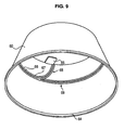
- the figure 9 shows an example of a sleeve made of elastomeric film 60, adapted to be fixed to a male protector 1 via a first end 64, the opposite end then being adapted to be folded over the protector 1 as previously described.
- the elastomeric film 60 forms a sleeve comprising a tongue 65 and two ribs 66 in order to define a pre-cutting zone 67 between these two ribs.
- the user can then pull on the tongue 65, which will cause tearing of the elastomeric film 60 at the precut region 67 located between the two zones of increased thickness defined by the two ribs 66, firstly according to a substantially longitudinal portion 68, then in a circular portion 69 for separating the elastomeric film 60.
- the elastomeric film 60 seals the connection between the male protector 1 and a tube on which it is fixed at the proximal end 21 of the male protector 1, without affecting the lubrication of the thread of the tube on which the protector is fixed.
Description
La présente invention concerne le domaine du conditionnement de tubes d'extraction de pétrole, et plus particulièrement les moyens d'étanchéité des protecteurs de filetages disposés aux extrémités de ces tubes.The present invention relates to the field of conditioning of oil extraction tubes, and more particularly to the sealing means of the thread protectors disposed at the ends of these tubes.
Les tubes d'extraction de pétrole sont utilisés pour la réalisation de forages de puits, afin d'atteindre des profondeurs importantes.The oil extraction tubes are used for the drilling of wells, in order to reach important depths.
Ces tubes présentent à chacune de leurs extrémités des filetages permettant de les relier entre eux soit directement, soit au moyen d'éléments intermédiaires.These tubes have at each of their ends threads for connecting them to each other either directly or by means of intermediate elements.
Les extrémités filetées des tubes sont qualifiées d'extrémités mâles, tandis que les extrémités taraudées des tubes sont qualifiées d'extrémités femelles.The threaded ends of the tubes are called male ends, while the threaded ends of the tubes are called female ends.
Conformément à la pratique de l'Homme de l'Art, un protecteur venant s'adapter sur une extrémité mâle d'un tube est qualifié de protecteur mâle (ou Pin), et un protecteur venant s'adapter sur une extrémité femelle d'un tube est qualifié de protecteur femelle (ou Box).In accordance with the practice of those skilled in the art, a protector fitting on a male end of a tube is called a male protector (or Pin), and a protector fitting on a female end of a tube is qualified as a female protector (or box).
De manière conventionnelle, ces filetages étaient lubrifiés une première fois avant leur stockage avec une graisse dite de stockage, puis à nouveau légèrement avant utilisation, avec un lubrifiant que l'on qualifie de « opérationnel ». Cela impliquait des pertes de temps importantes lors de chaque utilisation de ces tubes.Conventionally, these threads were lubricated a first time before storage with a so-called storage grease, then again slightly before use, with a lubricant that is described as "operational". This implied significant time losses during each use of these tubes.
Des tubes présentant des moyens de lubrification solides ou permanents au niveau de leurs filetages ont donc été proposés, visant ainsi à ne pas nécessiter des opérations de lubrification des filetages préalablement à chaque utilisation des tubes, les tubes étant alors lubrifiés de manière permanente dès leur fabrication.Tubes having solid or permanent lubrication means in their threads have therefore been proposed, so as not to require thread lubrication operations prior to each use of the tubes, the tubes then being permanently lubricated as soon as they are manufactured.
Les tubes d'extraction de pétrole nécessitent alors des protecteurs afin de protéger leurs extrémités filetées, de manière à ce que le filetage et le lubrifiant ne soit pas endommagé lors du stockage et des manutentions lors du transport des tubes.The oil extraction tubes then require protectors to protect their threaded ends, so that the thread and the lubricant is not damaged during storage and handling during the transportation of the tubes.
Ces protecteurs répondent avantageusement aux exigences suivantes :
- rester en place sur le tube malgré les vibrations du transport et les phases de manipulation des tubes,
- rester en place dans des conditions de température variant fortement, typiquement de -46°C à 66°C,
- jouer un rôle d'amortisseur de choc lors des différentes étapes de manipulation du tube,
- empêcher la pollution de l'intérieur du tube et des zones usinées, c'est-à-dire assurer l'étanchéité du tube,
- protéger les surfaces filetées contre l'humidité qui peut d'une part corroder ces surfaces et d'autre part dégrader le lubrifiant ;
- pouvoir être montés et démontés facilement,
- permettre un contrôle de l'intérieur du tube, communément désigné « Drift »; ce qui entraine la possibilité d'ouverture du protecteur en son extrémité au moyen d'un système de capsule qui ne nécessite pas de vissage et de dévissage du corps protecteur superflu,
- permettre la préhension, si besoin est, du tube par des crochets logés dans les extrémités du tube.
- stay in place on the tube despite the vibrations of the transport and the phases of manipulation of the tubes,
- remain in place under strongly varying temperature conditions, typically from -46 ° C to 66 ° C,
- play a role of shock absorber during the various stages of manipulation of the tube,
- to prevent pollution of the inside of the tube and of the machined zones, that is to say to ensure the tightness of the tube,
- protect the threaded surfaces against humidity that can corrode these surfaces and degrade the lubricant;
- can be easily assembled and disassembled,
- allow control of the inside of the tube, commonly referred to as "Drift"; which causes the possibility of opening the protector at its end by means of a capsule system which does not require screwing and unscrewing the superfluous protective body,
- allow the gripping, if necessary, the tube by hooks housed in the ends of the tube.
La norme API 5CT, également appelée ISO 11960 définit plus précisément les exigences auxquelles doivent répondre ces protecteurs.The API 5CT standard, also called ISO 11960 defines more precisely the requirements that these protectors must meet.
L'utilisation de lubrifiants solides vient ajouter une exigence supplémentaire de non dégradation de ces lubrifiants lors de la mise en position ou du retrait du protecteur.The use of solid lubricants adds an additional requirement of non-degradation of these lubricants during positioning or removal of the protector.
La demande de brevet
Ce protecteur amélioré peut présenter plusieurs variantes mâles ou femelles, de manière à s'adapter aux différentes extrémités de tubes.This improved protector can have several male or female variants, so as to adapt to different ends of tubes.
Le document
Dans sa variante mâle, le protecteur est avantageusement associé à un moyen assurant l'étanchéité de la liaison entre le protecteur et le tube. Ce moyen présente typiquement des propriétés particulières, notamment de manière à assurer une étanchéité suffisante sans dégrader le lubrifiant se trouvant sur le filetage lors de sa mise en place et de son retrait.In its male variant, the protector is advantageously associated with a means ensuring the sealing of the connection between the protector and the tube. This means typically has particular properties, especially so as to ensure a sufficient seal without degrading the lubricant on the thread during its introduction and its removal.
La présente invention vise à proposer un moyen de réalisation d'une liaison étanche entre un tube d'extraction de pétrole et un protecteur de filetage d'un tel tube.The present invention aims at providing a means for producing a tight connection between an oil extraction tube and a thread protector of such a tube.
A cet effet, l'invention propose un ensemble comprenant :
- o un tube d'extraction de pétrole muni d'un filetage ;
- o un protecteur dudit filetage du tube d'extraction, ledit protecteur comprenant un corps et un taraudage, typiquement discontinu, complémentaire au filetage dudit tube d'extraction,
- o an oil extraction tube with a thread;
- a protector of said thread of the extraction tube, said protector comprising a body and a tapping, typically discontinuous, complementary to the thread of said extraction tube,
Selon des modes de réalisation particuliers, ledit film élastomère est :
- un film monocouche de type ester uréthane, ou
- un film tri couche comprenant deux couches extérieures et une couche médiane, de composition éthylène propylène diène monomère sur les deux couches extérieures, et éthylène méthyle acrylate sur la couche intérieure, ou
- un film bi couche composé d'une première couche d'élasthanne et de polyhexaméthylène adipamide dans des proportions 20%/80% et d'une seconde couche de type ester uréthane.
- a monolayer urethane ester film, or
- a tri-layer film comprising two outer layers and a middle layer, of ethylene propylene diene monomer composition on the two outer layers, and ethylene methyl acrylate on the inner layer, or
- a bi-layer film composed of a first layer of elastane and polyhexamethylene adipamide in proportions of 20% / 80% and a second layer of urethane ester type.
Selon une variante, ledit film a une épaisseur comprise entre 0.001 mm et 5 mm.According to a variant, said film has a thickness of between 0.001 mm and 5 mm.
Selon une variante, ledit film est fixé au protecteur par collage ou au moyen d'un anneau soudé audit protecteur.According to a variant, said film is fixed to the protector by gluing or by means of a ring welded to said protector.
Selon une variante particulière, le protecteur présente une section sensiblement tronconique ayant une paroi interne, et le film est collé sur la paroi interne dudit protecteur.According to a particular variant, the protector has a substantially frustoconical section having an inner wall, and the film is adhered to the inner wall of said protector.
Selon un mode de réalisation particulier, le film présente un coefficient de glissement compris entre 0,05 et 0,5.According to a particular embodiment, the film has a sliding coefficient of between 0.05 and 0.5.
Selon une variante, le film forme un manchon ayant une longueur comprise entre 15 et 30 cm, ou telle que le ratio de la longueur du manchon par le diamètre du tube d'extraction est compris entre 0,5 et 10.According to a variant, the film forms a sleeve having a length of between 15 and 30 cm, or such that the ratio of the length of the sleeve to the diameter of the extraction tube is between 0.5 and 10.
Selon un mode de réalisation particulier, le film forme un manchon présentant une première extrémité fixée au protecteur, et une seconde extrémité libre, ledit manchon ayant sur au moins une partie de sa longueur un diamètre au repos inférieur au diamètre externe du tube.According to a particular embodiment, the film forms a sleeve having a first end attached to the protector, and a second free end, said sleeve having on at least a portion of its length a rest diameter less than the outer diameter of the tube.
L'invention concerne également un procédé d'assemblage d'un tel ensemble, comprenant les étapes suivantes :
- repli de la partie libre du manchon sur le protecteur sur la paroi externe du protecteur ;
- mise en place du protecteur sur le tube d'extraction,
- mise en place du manchon sur une section de la paroi externe du tube.
- folding of the free portion of the sleeve on the protector on the outer wall of the protector;
- placing the protector on the extraction tube,
- placing the sleeve on a section of the outer wall of the tube.
L'invention concerne en outre un procédé de fabrication d'un protecteur de filetage de tube d'extraction de pétrole, ledit procédé, comprenant les étapes suivantes:
- fabrication du protecteur par injection de polycarbonate,
- disposition d'un film élastomère entre une extrémité du protecteur et un anneau ;
- fixation de l'anneau sur le protecteur de manière à venir enserrer le film élastomère de façon permanente entre le protecteur et l'anneau.
- manufacture of the protector by polycarbonate injection,
- disposing an elastomeric film between one end of the protector and a ring;
- fixing the ring on the protector so as to grip the elastomeric film permanently between the protector and the ring.
D'autres caractéristiques, buts et avantages de l'invention ressortiront de la description qui suit, qui est purement illustrative et non limitative, et qui doit être lue en regard des dessins annexés, sur lesquels :
- les
figures 1 présentent une variante mâle d'un protecteur de tube d'extraction de pétrole ;et 2 - la
figure 3 présente un exemple de structure de film élastomère selon un mode de réalisation particulier ; - la
figure 4 présente un exemple de fixation de film élastomère sur un protecteur mâle au moyen d'un anneau ; - les
figures 5, 6 ,7 et 8 présentent des vues en coupe du positionnement d'un protecteur mâle muni d'un film élastomère sur un tube d'extraction ; - la
figure 9 présente un exemple de mode de réalisation particulier de manchon en film élastomère.
- the
Figures 1 and 2 present a male variant of a petroleum extraction tube protector; - the
figure 3 shows an example of an elastomeric film structure according to a particular embodiment; - the
figure 4 shows an example of fixing elastomeric film on a male protector by means of a ring; - the
Figures 5, 6 ,7 and 8 show sectional views of the positioning of a male protector provided with an elastomeric film on an extraction tube; - the
figure 9 presents an example of a particular embodiment of an elastomeric film sleeve.
La
Le protecteur mâle 1 tel qu'illustré comprend un corps pouvant être décomposé en deux parties :
- un segment de
liaison 2, et - un segment pare
choc 3.
- a
link segment 2, and - a
bumper segment 3.
Le segment de liaison 2 présente une extrémité proximale 21 et une extrémité distale 22, et a une forme sensiblement tronconique dont le diamètre diminue de l'extrémité proximale 21 vers l'extrémité distale 22.The connecting
Le segment pare choc 3 présente quant à lui une extrémité de liaison 31 et une extrémité libre 32, son extrémité de liaison 31 étant dans le prolongement de l'extrémité distale 22 du segment de liaison 2.The
Le segment pare choc 3 comprend une couronne interne 33 et une couronne externe 34, ces deux couronnes 33 et 34 étant concentriques et définissant entre elles un espace interne 35.The
La couronne interne 33 telle que représentée comprend une portion tronconique dans le prolongement de l'extrémité distale 22 du segment de liaison 2, et une portion ayant une forme de cylindre creux dans le prolongement de cette portion tronconique, le diamètre de cette section cylindrique correspondant sensiblement au diamètre interne du tube sur lequel le protecteur mâle est destinée à être positionné.The
La couronne interne 33 est ainsi typiquement décalée radialement par rapport au segment de liaison 2 tronconique et comprend ainsi typiquement une cloison de liaison 23, visible sur la
Le protecteur mâle 1 illustré présente deux rainures 40 s'étendant selon un diamètre du protecteur mâle 1, à partir de l'extrémité libre 32.The
Ces rainures 40 sont adaptées pour permettre d'y insérer un outil pour le vissage et le dévissage du protecteur sur un tube.These
Ces rainures 40 présentent de plus des orifices 41 aménagés sur une de leurs parois, ces orifices 41 étant destinés à permettre la fixation d'une capsule sensiblement circulaire venant obstruer l'extrémité libre 32 du protecteur mâle 1.These
La
Dans ces deux modes de réalisation 45 et 46, les capsules comprennent des saillies 47 complémentaires aux orifices 41 du protecteur mâle 1, de manière à être maintenues en position au niveau de son extrémité libre 32.In these two
Le mode de réalisation 45 de la capsule vient recouvrir toute son extrémité libre 32, et a un diamètre correspondant au diamètre maximum du protecteur mâle 1.The
Le mode de réalisation 46 se contente pour sa part de venir obstruer l'ouverture définir par la couronne interne 33, et a donc un diamètre correspondant sensiblement au diamètre interne de cette couronne interne 33.
Dans le mode de réalisation illustré, le protecteur mâle 1 comprend des nervures 36 longitudinales venant relier la couronne interne 33 et la couronne externe 34, et segmentant ainsi l'espace interne 35 entre la couronne interne 33 et la couronne externe 34 en de multiples compartiments.In the illustrated embodiment, the
Tel que représenté sur la figure, le protecteur mâle 1 comprend douze nervures 36 longitudinales, les côtés de chacune des rainures 40 sont délimités par deux nervures 36, et les nervures 36 restantes sont réparties de manière sensiblement uniforme entre la couronne interne 33 et la couronne externe 34.As shown in the figure, the
Tel qu'illustré, l'extrémité libre 32 du protecteur mâle 1 est biseautée à sensiblement 45%, résultant en un rétrécissement du diamètre en allant vers l'extrémité libre 32. Cette inclinaison à 45% permet d'augmenter la résistance du protecteur mâle 1 aux chocs, et ainsi de protéger plus efficacement le tube sur lequel il est destiné à être monté qu'un protecteur ayant une extrémité libre 32 à angle droit.As illustrated, the
Le protecteur mâle 1 comprend par ailleurs des filets 42 disposés au niveau de la paroi interne du segment de liaison 2, ces filets 42 étant adaptés pour venir coopérer avec les filets d'un tube sur lequel ledit protecteur mâle 1 est destiné à être assemblé. Ces filets 42 forment un filetage mâle, sont typiquement réalisés par taraudage, et sont avantageusement discontinus.The
Les filets 42 du protecteur mâle 1 comprennent typiquement une, deux ou trois spires, d'autres variantes étant bien entendu possibles.The
Un nombre réduit de spires permet de limiter l'impact sur le lubrifiant des filets du tube que le protecteur mâle 1 est destiné à protéger, ce nombre de spires étant toutefois choisi de manière à assurer un maintien suffisant du protecteur mâle 1 sur le tube.A reduced number of turns makes it possible to limit the impact on the lubricant of the threads of the tube that the
Le protecteur mâle 1 est réalisé en polycarbonate par injection.The
La géométrie spécifique du protecteur 1 présente des avantages importants pour sa réalisation par injection. En effet, l'ensemble des parois du protecteur 1 ont une épaisseur sensiblement égale, y compris les parois du segment pare choc 3 en raison de la présence des nervures 36.The specific geometry of the
Cette épaisseur sensiblement constante sur l'ensemble du protecteur mâle permet :
- d'éviter les retassures,
- de réduire la quantité de matière nécessaire,
- de réduire fortement le temps de solidification par rapport à une pièce équivalente où le segment pare
choc 3 serait réalisé « plein », ce qui permet donc de réduire fortement le temps d'immobilisation de la machine d'injection en réduisant la durée de cycle pour la réalisation du protecteur mâle 1, permettant ainsi de réaliser une économie d'énergie et d'avoir une cadence de production plus élevée ; - éviter les points dit chauds qui sont des points des concentration de contraintes et donc des points faibles mécaniquement.
- to avoid sinkholes,
- to reduce the amount of material needed,
- greatly reduce the solidification time compared to an equivalent part where the
bumper segment 3 would be made "full", which thus greatly reduces the downtime of the injection machine by reducing the cycle time for the embodiment of themale protector 1, thus making it possible to save energy and to have a higher production rate; - avoid the so-called hot points which are points of stress concentration and therefore weak points mechanically.
Ainsi, le protecteur 1 tel que décrit présente un cout de production réduit par rapport à un protecteur de forme globale équivalente, mais dont le segment pare choc 3 serait « plein ».Thus, the
De plus, l'ensemble des liaisons et des arêtes présente avantageusement des congés ou des arrondis afin que le protecteur 1 ne comprenne pas d'angles vifs, ce qui permet de favoriser le démoulage. Par ailleurs, le fait de ne pas comprendre d'angles vifs permet d'éviter les risques de dégradation du film qui sera décrit ci-après.In addition, all the connections and ridges advantageously have fillets or rounds so that the
Le polycarbonate est un matériau très performant pour la réalisation du protecteur 1, dont l'injection est rendue possible en raison de la forme spécifique du protecteur.Polycarbonate is a very efficient material for the production of the
De plus, le polycarbonate est un matériau transparent, ce qui permet à l'utilisateur de contrôler directement l'état des filets du tube sur lequel le protecteur 1 est positionné, sans qu'il soit nécessaire de retirer le protecteur 1 pour procéder à un tel contrôle.In addition, the polycarbonate is a transparent material, which allows the user to directly control the state of the threads of the tube on which the
Cette facilité de contrôle permet d'éviter les risques de détérioration de la lubrification des filets du tube à chaque retrait et repositionnement du protecteur 1.This ease of control makes it possible to avoid the risk of deterioration of the lubrication of the threads of the tube at each removal and repositioning of the
En outre, le protecteur 1 est avantageusement soumis à un traitement de surface, afin de réaliser un filtrage des ultraviolets et/ou infrarouges, un tel traitement étant typiquement composé d'un trempage, puis d'un traitement plasma sous micro ondes en présence d'ozone.In addition, the
Le matériau dont est constitué le protecteur 1, typiquement du polycarbonate, peut être choisi de manière à présenter de telles caractéristiques de filtrage des ultraviolets et/ou infrarouges.The material of which the
Les lubrifiants solides utilisés sur les filets des tubes peuvent en effet être sensibles aux ultraviolets et infrarouges, et doivent donc en être protégés.The solid lubricants used on tube threads can indeed be sensitive to ultraviolet and infrared, and must therefore be protected.
Ainsi, les protecteurs mâle 1 proposés permettent de protéger efficacement les extrémités filetées d'un tube d'extraction de pétrole, en réalisant une liaison étanche tout en autorisant les différentes opérations de manutention et de contrôle du tube, et en conservant un coût de production raisonnable du fait de leur forme spécifiquement adaptée à l'injection.Thus, the
Le protecteur mâle 1 tel que représenté sur la
Le film élastomère 60 est typiquement un film élastomère comprenant une ou plusieurs couches, et présentant avantageusement tout ou partie des propriétés suivantes :
- présenter une face ayant une très faible adhérence, cette surface étant celle destinée à venir au contact du tube, de manière à limiter les frottements sur les filets du tube lorsque le protecteur 1 est retiré du tube et ainsi ne pas détériorer le lubrifiant lors du retrait du protecteur ; cette très faible adhérence est typiquement obtenue via l'ajout d'un agent glissant, par exemple la molécule d'Erucamide dans une proportion comprise entre 0.1 et 50% de la structure globale ;
- être rétractable/étirable, de manière à permettre à la fois son repliement sur le protecteur préalablement à la mise en position du protecteur 1 sur le tube, puis son déroulement ou rabattement sur la face externe du tube une fois le protecteur 1 mis en position sur ledit tube, tout en assurant l'étanchéité de la liaison malgré un diamètre inférieur à celui du tube;
- être soudable sur lui-même ;
- être imperméable à l'humidité ;
- présenter des propriétés mécaniques suffisantes pour que le film ne se déchire pas lors des étapes de mise en place du film sur le protecteur et du protecteur 1 sur le tube, plus précisément le film présente une résistance importante à la torsion et au cisaillement.
- have a side having a very low adhesion, this surface being that intended to come into contact with the tube, so as to limit friction on the threads of the tube when the
protector 1 is removed from the tube and thus not to deteriorate the lubricant during withdrawal protector; this very low adhesion is typically obtained via the addition of a slip agent, for example the Erucamide molecule in a proportion of between 0.1 and 50% of the overall structure; - to be retractable / stretchable, so as to allow both its folding on the protector prior to the positioning of the
protector 1 on the tube, and then unwinding or folding on the outer face of the tube once theprotector 1 set in position on said tube, while ensuring the sealing of the connection despite a smaller diameter than the tube; - to be weldable on itself;
- be impervious to moisture;
- have sufficient mechanical properties so that the film does not tear during the steps of placing the film on the protector and the
protector 1 on the tube, specifically the film has a significant resistance to torsion and shear.
Selon un premier mode de réalisation avantageux, le film élastomère est un film monocouche de type ester uréthane, par exemple le film commercialisé sous la référence Vacfilm 430 par la société Richmond Aerovac.According to a first advantageous embodiment, the elastomeric film is a monolayer urethane ester film, for example the film sold under the reference Vacfilm 430 by the company Richmond Aerovac.
Le film a une épaisseur utile typiquement comprise entre 0.001 mm et 5 mm, par exemple entre 100 et 200 µm, typiquement de l'ordre ou égale à 100 ou 200 µm.The film has a useful thickness typically between 0.001 mm and 5 mm, for example between 100 and 200 microns, typically of the order or equal to 100 or 200 microns.
Selon un second mode de réalisation, le film élastomère est un film tri couche de composition EPDM (éthylène propylène diène monomère) sur les couches externes, et EMA (éthylène méthyle acrylate) sur la couche interneAccording to a second embodiment, the elastomeric film is a tri-layer film of composition EPDM (ethylene propylene diene monomer) on the outer layers, and EMA (ethylene methyl acrylate) on the inner layer
Le film a une épaisseur utile typiquement comprise entre 0.001 mm et 5 mm, par exemple de l'ordre ou égale à 200 µm.The film has a useful thickness typically between 0.001 mm and 5 mm, for example of the order or equal to 200 microns.
Un additif glissant, par exemple la molécule d'Erucamide dans une proportion comprise entre 0.1 et 50% de la masse de l'EPDM est typiquement ajouté à l'EPDM de manière à réduire son adhérence, par exemple pour avoir un coefficient de glissement compris entre 0,05 et 0,80.A slip additive, for example the Erucamide molecule in a proportion of between 0.1 and 50% of the mass of the EPDM is typically added to the EPDM in order to reduce its adhesion, for example to have a slip coefficient included between 0.05 and 0.80.
La
- la première couche externe 61 qui est la couche destinée à venir au contact du tube, et est typiquement réalisée en EPDM auquel est avantageusement ajouté un additif glissant ;
- la deuxième couche médiane 62, est la couche destinée à ajouter la souplesse au film global, et est typiquement réalisée en EMA. Cette couche ne contient pas d'agent glissant, ce qui permet notamment d'assurer la compatibilité entre les couches ;
- la troisième couche externe 63, qui est la couche destinée à être au contact du protecteur 1, est par exemple également réalisée en EPDM auquel est avantageusement ajouté un additif glissant.
- the first
outer layer 61 which is the layer intended to come into contact with the tube, and is typically made of EPDM which is advantageously added a slip additive; - the second
middle layer 62 is the layer for adding flexibility to the overall film, and is typically made of EMA. This layer does not contain a sliding agent, which makes it possible in particular to ensure compatibility between the layers; - the third
outer layer 63, which is the layer intended to be in contact with theprotector 1, is for example also made of EPDM which is advantageously added a slip additive.
Le film 60 présente ainsi les propriétés suivantes :
- Pourcentage d'allongement typiquement compris entre 50% et 1500%, typiquement entre 200 et 800%, et plus particulièrement entre 300 et 600% ;
- Coefficient de glissement compris entre 0,05 et 0,8 ;
- Epaisseur comprise entre 50 µm et 300 µm ;
- Soudabilité possible dès 105°C à 330 bar pendant 1seconde.
- Percent elongation typically between 50% and 1500%, typically between 200 and 800%, and more particularly between 300 and 600%;
- Slip coefficient between 0.05 and 0.8;
- Thickness between 50 μm and 300 μm;
- Weldability possible from 105 ° C to 330 bar for 1second.
Le coefficient de glissement, également appelé coefficient de frottement est défini par la loi de Coulomb, qui définit pour deux solides glissant l'un par rapport à l'autre, T = f x N, où :
- T est la composante tangentielle des forces de frottements s'exerçant au niveau du contact entre les deux solides, qui s'oppose ou tend à s'opposer au glissement,
- N est la composante normale des forces de frottements s'exerçant au niveau du contact entre les deux solides, qui les presse l'un contre l'autre.
- T is the tangential component of friction forces acting at the contact between the two solids, which opposes or tends to oppose sliding,
- N is the normal component of the friction forces acting on the contact between the two solids, which presses them against each other.
Afin d'obtenir un film aux propriétés souhaitées, on utilise par exemple des polymères linéaires ou à faible densité, qui permettent d'obtenir un film souple.In order to obtain a film with the desired properties, linear or low density polymers are used, for example, which make it possible to obtain a flexible film.
En outre, les polymères semi-cristallins de faible densité ont une phase amorphe plus importante, et permettent donc une additivation mieux contrôlée car les charges se logent dans la phase amorphe.In addition, the semi-crystalline polymers of low density have a larger amorphous phase, and thus allow a more controlled additivation because the charges are housed in the amorphous phase.
Selon un troisième mode de réalisation, le film élastomère est un film bi couche composé d'une première couche d'élasthanne, par exemple en matériau commercialisé sous le nom Lycra (marque déposée par un tiers), ou un mélange d'élasthanne et de Polyhexaméthylène adipamide, commercialisé sous le nom nylon (marque déposée par un tiers), par exemple dans des proportions 20%/80%, et d'une seconde couche de type ester uréthane, par exemple le film commercialisé sous la référence Vacfilm 430 par la société Richmond Aerovac.According to a third embodiment, the elastomeric film is a two-layer film composed of a first layer of elastane, for example material sold under the name Lycra (trademark of a third party), or a mixture of elastane and Polyhexamethylene adipamide, sold under the name nylon (trademark registered by a third party), for example in proportions of 20% / 80%, and a second urethane ester layer, for example the film marketed under the reference Vacfilm 430 by the Richmond Aerovac company.
Le film bi couche ainsi formé a une épaisseur utile typiquement comprise entre 0.001 mm et 5 mm, par exemple de l'ordre ou égale à 1050 µm, correspondant à 1000 µm de la première couche de Lycra et 50 µm de la seconde couche.The bi-layer film thus formed has a useful thickness typically between 0.001 mm and 5 mm, for example of the order or equal to 1050 microns, corresponding to 1000 microns of the first layer of Lycra and 50 microns of the second layer.
Le film élastomère 60 est mis en forme de manière à former un tube ou manchon, et est fixé au protecteur mâle 1.The
Cette fixation peut par exemple être réalisée par collage du film 60 directement sur le protecteur 1, ou par soudage ou encastrement d'un anneau au protecteur 1 de manière à venir enserrer le film 60.This attachment may for example be made by bonding the
Dans le cas de la fixation par collage, on peut réaliser les étapes suivantes :
- découpe du film élastomère en bandes, ayant typiquement des dimensions de l'ordre de 130mm par 330mm, ou plus généralement une largeur comprise entre 100 et 200mm et une longueur comprise entre 300 et 360 mm ;
- soudure du film de manière à former un manchon, typiquement réalisée en mettant bout à bout deux bords d'une bande de film et en les soudant, de manière à éviter de former une surépaisseur, le manchon ainsi formé ayant une longueur typiquement comprise entre 15 et 30 cm ;
- mise en position du manchon ainsi formé sur un cylindre d'élastomère gonflable, puis positionnement de ce cylindre à l'intérieur d'un protecteur mâle ;
- pré-gonflage du cylindre d'élastomère, jusqu'à ce qu'il soit en contact avec le manchon ;
- ajout d'une bande d'adhésif, typiquement ajout de colle par transfert de colle sur tout le tour du manchon, cette bande de colle ayant par exemple une largeur inférieure ou égale à 50 mm ;
- poursuivre le gonflage du cylindre d'élastomère jusqu'à un contact entre le film et le protecteur et créer ainsi une surpression, typiquement de l'ordre de 2 bar, pendant une durée donnée, par exemple une minute, de manière à assembler le film élastomère 60 et le protecteur 1, typiquement au niveau de la paroi interne d'une section tronconique du protecteur 1 dans le cas du mode de réalisation particulier présenté précédemment ;
- dégonfler le cylindre élastomère puis le retirer de l'assemblage ainsi formé.
- cutting elastomeric film strips, typically having dimensions of the order of 130mm by 330mm, or more generally a width of between 100 and 200mm and a length of between 300 and 360 mm;
- welding the film so as to form a sleeve, typically made by butt-joining two edges of a film strip and welding them, so as to avoid forming an excess thickness, the sleeve thus formed having a length of typically between and 30 cm;
- positioning the sleeve thus formed on an inflatable elastomer cylinder, and positioning the cylinder inside a male protector;
- pre-inflating the elastomer cylinder until it contacts the sleeve;
- adding a band of adhesive, typically glue transfer adhesive added all round the sleeve, this adhesive strip having for example a width less than or equal to 50 mm;
- continue inflation of the elastomer cylinder until contact between the film and the protector and thus create an overpressure, typically of the order of 2 bar, for a given duration, for example one minute, so as to assemble the
elastomeric film 60 and theprotector 1, typically at the inner wall of a frustoconical section of theprotector 1 in the case of particular embodiment presented previously; - deflate the elastomeric cylinder and remove it from the assembly thus formed.
L'adhésif est choisi de manière à ce que la fixation du film polymère 60 sur le protecteur mâle 1 soit définitive, c'est-à-dire que le film polymère 60 ne puisse pas être retiré du protecteur mâle sans se dégrader, contrairement à une fixation amovible.The adhesive is chosen so that the fixing of the
Selon une autre variante, le film élastomère 60 peut être fixé au protecteur 1 au moyen d'un anneau 70 soudé au protecteur 1.According to another variant, the
La
Dans ce mode de réalisation, la fixation du film 60 sur le protecteur 1 peut comprendre les étapes suivantes :
- découpe du film en bandes, ayant typiquement des dimensions de l'ordre de 130 mm par 330 mm ou plus généralement une largeur comprise entre 100 et 300 mm et une longueur comprise entre 300 et 360 mm, ces dimensions correspondant typiquement à la circonférence d'un tube de diamètre 4"1/2 ; d'autres dimensions pouvant être utilisées ;
- soudure du film de manière à former un manchon, typiquement réalisée en mettant bout à bout deux bords d'une bande de film et en les soudant, de manière à éviter de former une surépaisseur, le manchon ainsi formé ayant une longueur typiquement comprise entre 15 et 30 cm;
- réalisation d'un anneau 70, par exemple un anneau à godrons en polycarbonate, typiquement par injection, ayant par exemple un diamètre intérieur de 114mm ;
- disposition du
film 60 entre le protecteur 1et l'anneau 70, typiquement à l'extrémité proximale 21 du protecteur 1 ; - fixation de l'anneau 70 sur le protecteur 1, typiquement par soudure ultra-son ou encastrement.
- cutting the film into strips, typically having dimensions of the order of 130 mm by 330 mm or more generally a width of between 100 and 300 mm and a length of between 300 and 360 mm, these dimensions typically corresponding to the circumference of a 4 "1/2 diameter tube, other dimensions that can be used;
- welding the film so as to form a sleeve, typically made by butt-joining two edges of a film strip and welding them, so as to avoid forming an excess thickness, the sleeve thus formed having a length of typically between and 30 cm;
- producing a
ring 70, for example a polycarbonate fluted ring, typically by injection, having for example an internal diameter of 114 mm; - arranging the
film 60 between theprotector 1 and thering 70, typically at theproximal end 21 of theprotector 1; - fixing the
ring 70 on theprotector 1, typically by ultrasonic welding or embedding.
Le film élastomère 60 est ainsi fixé de manière permanente sur le protecteur 1.The
En variante, le film 60 peut être préfixé à l'anneau 70 préalablement à sa mise en position sur le protecteur 1, de manière à faciliter sa mise en place.Alternatively, the
Le manchon réalisé en film élastomère 60 présente typiquement une longueur comprise entre 15 et 30 cm, ou par exemple une longueur telle que le ratio de la longueur du manchon par le diamètre du tube d'extraction est compris entre 0,5 et 10.The sleeve made of
Une fois fixé au protecteur mâle 1, le film élastomère 60 est typiquement replié autour de l'extrémité proximale 21 de manière à venir recouvrir la paroi externe du protecteur mâle 1, comme illustré sur la
Le manchon présente typiquement une première extrémité fixée au protecteur 1, et une seconde extrémité libre.The sleeve typically has a first end attached to the
Selon un mode de réalisation particulier, le film élastomère 60 est dimensionné et présente des propriétés d'étirement de sorte que le manchon a sur au moins une partie de sa longueur, un diamètre au repos (lorsqu'il n'est pas étiré) inférieur au diamètre externe du tube 4, le manchon pouvant être étiré pour sa mise en place et son repliement sur le protecteur 1.According to a particular embodiment, the
Le protecteur mâle 1 est ensuite mis en position sur un tube d'extraction de pétrole, typiquement en venant le visser à une extrémité du tube. Lors de cette mise en place, le film élastomère vient glisser sur le filetage du tube, sans en dégrader le lubrifiant du fait des propriétés du film élastomère 60, notamment son adhérence et son coefficient de glissement.The
Selon une première variante, la partie du film élastomère 60 qui était repliée sur la face externe du protecteur mâle 1 est ensuite déroulée ou rabattu de manière à venir recouvrir une partie du tube, typiquement une longueur comprise entre 15 et 30 cm. Le manchon enserre alors le tube 4 du fait de son diamètre inférieur au diamètre externe du tube 4. La
Selon une autre variante, la partie du film élastomère 60 qui était repliée sur la face externe du protecteur mâle 1 est ensuite séparée de la partie du film élastomère 60 fixée au protecteur 1, typiquement par déchirement ou par découpe. Cette séparation du film élastomère 60 est avantageusement réalisée sensiblement au niveau de l'extrémité proximale 22 du segment de liaison 2 du protecteur 1. Une fois cette séparation réalisée, la partie du film élastomère 60 fixée au protecteur 1 se rétracte sur le tube fileté 4 du fait de son diamètre inférieur au diamètre externe du tube 4.According to another variant, the portion of the
Le film élastomère 60 présente alors avantageusement une ou plusieurs prédécoupes, afin de faciliter sa séparation.The
Les
La
L'utilisateur peut alors tirer sur la languette 65, ce qui va entrainer une déchirure du film élastomère 60 au niveau de la zone de prédécoupe 67 située entre les deux zones d'épaisseur accrue définies par les deux nervures 66, tout d'abord selon une portion sensiblement longitudinale 68, puis selon une portion circulaire 69 permettant de réaliser la séparation du film élastomère 60.The user can then pull on the
Ainsi, le film élastomère 60 réalise l'étanchéité de la liaison entre le protecteur mâle 1 et un tube sur lequel il est fixé au niveau de l'extrémité proximale 21 du protecteur mâle 1, sans affecter la lubrification du filetage du tube sur lequel le protecteur est fixé.Thus, the
Claims (14)
- Assembly comprising:o an oil extraction tube (4) provided with a thread;o a protector (1) of said thread of the extraction tube (4), said protector (1) comprising a body and a tapping complementary to the thread of said extraction tube (4),said assembly being characterised in that it also comprises an elastomer film (60) fixed to said protector, and adapted to make a sealed connection between the extraction tube (4) and the protector (1) when said protector (1) is put in position on the extraction tube (4).
- Assembly according to the previous claim, wherein said elastomer film (60) is a urethane ester type single layer film.
- Assembly according to claim 1, wherein said elastomer film (60) is a three-layer film comprising two external layers (61, 63) and a median layer (62), with an ethylene propylene diene monomer composition on the external layers (61) and an ethylene methyl acrylate composition on the median layer (62).
- Assembly according to one of the previous claims, wherein said film (60) is between 0.001 mm and 5 mm thick.
- Assembly according to one of the previous claims, wherein the coefficient of friction of said film is between 0.05 and 0.5.
- Assembly according to one of the previous claims, wherein said film (60) forms a sleeve with a first end fixed to the protector (1) and a free second end, the diameter of said sleeve at rest being less than the outside diameter of the tube (4) over at least part of the length of the sleeve.
- Assembly according to any one of the previous claims, wherein said film (60) is fixed to the protector (1) by gluing.
- Assembly according to one of the previous claims, wherein the protector (1) has an substantially frustoconical section having an inside wall, and the film (60) is glued onto the inside wall of said protector (1).
- Assembly according to one of claims 1 to 6, wherein the film (60) is fixed to the protector (1) by means of a ring (70) fixed to said protector (1).
- Assembly according to one of the previous claims, wherein the film forms a sleeve having a length of between 15 and 30 cm.
- Assembly according to one of claims 1 to 9, wherein said film (60) forms a having with a length such that the ratio of the sleeve length to the diameter of the extraction tube (4) is between 0.5 and 10.
- Assembly according to one of the previous claims, wherein said film (60) can be welded to itself and is impermeable to moisture.
- Method for assembling an assembly according to claim 6, including the following steps:- folding the free part of the sleeve on the protector (1) onto the outside wall of the protector (1) ;- putting the protector (1) into place on the extraction tube (4);- putting the sleeve into place on a section of the outside wall of the tube (4).
- Method for manufacturing a protector (1) for a thread of an oil extraction tube (4), said method being characterised in that it includes the following steps:- manufacturing the protector (1) by injection of polycarbonate;- positioning an elastomer film (60) between one end of the protector (1) and a ring (70);- attaching the ring (70) onto the protector (1) so as to enclose the elastomer film (60) permanently between the protector (1) and the ring (70).
Applications Claiming Priority (3)
| Application Number | Priority Date | Filing Date | Title |
|---|---|---|---|
| FR1057020A FR2964408B1 (en) | 2010-09-03 | 2010-09-03 | PETROLEUM EXTRACTION TUBE PROTECTOR |
| FR1061379A FR2964409B1 (en) | 2010-09-03 | 2010-12-30 | POLYMERIC FILM FOR THE PACKAGING OF PETROLEUM EXTRACTION TUBES |
| PCT/EP2011/065140 WO2012028692A1 (en) | 2010-09-03 | 2011-09-01 | Polymer film for the conditioning of oil extraction pipes |
Publications (2)
| Publication Number | Publication Date |
|---|---|
| EP2611983A1 EP2611983A1 (en) | 2013-07-10 |
| EP2611983B1 true EP2611983B1 (en) | 2015-06-17 |
Family
ID=43708254
Family Applications (2)
| Application Number | Title | Priority Date | Filing Date |
|---|---|---|---|
| EP11730032.7A Active EP2611982B1 (en) | 2010-09-03 | 2011-07-08 | Drill pipe protector |
| EP11757228.9A Not-in-force EP2611983B1 (en) | 2010-09-03 | 2011-09-01 | Polymer film for conditioning a drill pipe |
Family Applications Before (1)
| Application Number | Title | Priority Date | Filing Date |
|---|---|---|---|
| EP11730032.7A Active EP2611982B1 (en) | 2010-09-03 | 2011-07-08 | Drill pipe protector |
Country Status (10)
| Country | Link |
|---|---|
| US (2) | US9151433B2 (en) |
| EP (2) | EP2611982B1 (en) |
| JP (2) | JP5845262B2 (en) |
| CN (2) | CN103210173B (en) |
| BR (2) | BR112013005039A2 (en) |
| EA (2) | EA028276B1 (en) |
| ES (2) | ES2806254T3 (en) |
| FR (2) | FR2964408B1 (en) |
| MX (2) | MX337435B (en) |
| WO (2) | WO2012028365A1 (en) |
Families Citing this family (8)
| Publication number | Priority date | Publication date | Assignee | Title |
|---|---|---|---|---|
| US9995100B1 (en) * | 2011-01-25 | 2018-06-12 | Steven M Bogush | Tamper-evident sealing device for wells |
| FR2998639B1 (en) * | 2012-11-26 | 2014-11-28 | Vallourec Mannesmann Oil & Gas | DEVICE FOR PROTECTING A MALE END OF A FLEXIBLE TUBULAR THREADED JOINT COMPONENT |
| CN104389531B (en) * | 2014-11-26 | 2016-05-25 | 中国海洋石油总公司 | A kind of casing screw protector cap |
| FR3030676A1 (en) | 2014-12-23 | 2016-06-24 | Vallourec Oil & Gas France | DEVICE FOR PROTECTING AN END OF A FLEXIBLE TUBULAR THREADED JOINT COMPONENT |
| EP3633135B1 (en) * | 2018-10-02 | 2020-09-02 | Vallourec Oil And Gas France | Protective device for a male end portion of a steel tube intented for use in a tubular hydrocarbon working string |
| GB2578754A (en) * | 2018-11-06 | 2020-05-27 | Tubular Multi Prot As | Protector for drill pipe end |
| US20220243856A1 (en) | 2021-02-04 | 2022-08-04 | Universal Moulding Co. Ltd. | Pipe thread protector with removable end member and interference-fit protrusion |
| TWI803290B (en) * | 2022-04-20 | 2023-05-21 | 國立雲林科技大學 | Connection device for multi-channel groundwater extraction pipe |
Family Cites Families (43)
| Publication number | Priority date | Publication date | Assignee | Title |
|---|---|---|---|---|
| US196270A (en) * | 1877-10-16 | Improvement in combination writing instruments | ||
| US1859311A (en) * | 1926-06-01 | 1932-05-24 | Jr Joseph H Mcevoy | Pipe joint |
| US2098087A (en) * | 1936-06-18 | 1937-11-02 | Spang Chalfant And Co Inc | Pipe thread protector |
| US2316013A (en) * | 1941-03-22 | 1943-04-06 | Mulholland Thomas | Pipe thread protector |
| US2407553A (en) * | 1945-02-15 | 1946-09-10 | Flow Controls Inc | Pipe thread gasket |
| US2523930A (en) * | 1945-05-05 | 1950-09-26 | Herman A Unke | Thread protector |
| GB709809A (en) | 1951-03-08 | 1954-06-02 | Roneo Ltd | Improved method and apparatus for electrically producing copying stencils |
| FR1237569A (en) * | 1958-10-14 | 1960-07-29 | Lubricating and sealing tape for threaded joints | |
| US3687493A (en) * | 1971-03-01 | 1972-08-29 | Exxon Production Research Co | Threaded connection |
| US3780773A (en) * | 1971-06-17 | 1973-12-25 | S Haugen | Closure for multiple passage conduit |
| US4020874A (en) * | 1975-09-05 | 1977-05-03 | Precise Metals & Plastic, Inc. | Thermoplastic thread protector for internally threaded pipe |
| US4157100A (en) * | 1977-08-17 | 1979-06-05 | John Turk | Thread protector device |
| US4139023A (en) * | 1977-12-05 | 1979-02-13 | Turley William M | Pipe thread protector |
| US4379471A (en) * | 1978-11-02 | 1983-04-12 | Rainer Kuenzel | Thread protector apparatus |
| US4662402A (en) * | 1979-09-24 | 1987-05-05 | Wilfried Dreyfuss | System for protecting machine threads |
| US4337799A (en) * | 1980-09-22 | 1982-07-06 | Hoover C Roger | Thread protector |
| US4796668A (en) * | 1984-01-09 | 1989-01-10 | Vallourec | Device for protecting threadings and butt-type joint bearing surfaces of metallic tubes |
| FR2557953B1 (en) * | 1984-01-09 | 1986-07-18 | Vallourec | PROTECTIVE DEVICE FOR THREADED TUBE JUNCTION ELEMENTS |
| US4674773A (en) * | 1984-01-23 | 1987-06-23 | Teleco Oilfield Services Inc. | Insulating coupling for drill collars and method of manufacture thereof |
| JPS60154267U (en) * | 1984-03-26 | 1985-10-15 | 住友金属工業株式会社 | screw protector |
| CN85108884B (en) * | 1985-12-03 | 1987-04-08 | 华东石油学院北京研究生部 | Protection equipment for injecting water sleeve in oil field |
| US5244015A (en) * | 1987-06-30 | 1993-09-14 | Drilltec Patents & Technologies Co. | Pipe-end protector |
| US5195562A (en) * | 1988-06-29 | 1993-03-23 | Drilltec Patents & Technologies Co. | Pipe-end protector |
| US4957141A (en) * | 1988-06-29 | 1990-09-18 | Wilfried Dreyfuss | Pipe-end protector |
| US5352383A (en) * | 1991-10-18 | 1994-10-04 | Centrax International Corp. | Corrosion inhibitor and sealable thread protector end cap for tubular goods |
| ID26896A (en) * | 1998-05-22 | 2001-02-15 | Drilltec Patents & Tech | SCREW PROTECTOR |
| JP2003240188A (en) * | 2002-02-14 | 2003-08-27 | Sumitomo Metal Ind Ltd | Screw protecting protector for pipe joint |
| US7281546B2 (en) * | 2003-04-11 | 2007-10-16 | Hunting Energy Services, Inc. | Thread protection system with weather barrier |
| US20040201131A1 (en) * | 2003-04-11 | 2004-10-14 | Goodson H. Dean | Thread protection system and article of manufacture |
| US7571936B2 (en) * | 2003-07-17 | 2009-08-11 | Harald Schneider | Screw connection element and protective sleeve therefor |
| JP2005256957A (en) * | 2004-03-11 | 2005-09-22 | Kurimoto Ltd | Pipe end corrosion-proof structure |
| CN1704319A (en) | 2004-06-01 | 2005-12-07 | 天津市津英达塑料制品有限责任公司 | Method of making full-plastic foaming type screw thread protector |
| US7469721B2 (en) | 2004-08-25 | 2008-12-30 | Sumitomo Metal Industries, Ltd. | Thread protector for a pipe |
| AR052967A1 (en) * | 2005-05-27 | 2007-04-18 | Siderca Sa Ind & Com | A PROTECTOR FOR THE END OF A TUBULAR ELEMENT AND TUBULAR ELEMENT THAT UNDERSTANDS IT |
| UA92374C2 (en) * | 2005-11-15 | 2010-10-25 | Тред Гард Текнолоджи Лтд. | Assembled protector for a pipe end provided with external or internal thread |
| AR051775A1 (en) * | 2005-11-22 | 2007-02-07 | Siderca Sa Ind & Com | A PROTECTIVE ASSEMBLY FOR THE EXTREME THREADED OF A TUBE AND OF ITS INTERIOR THAT INCLUDES AN OPEN THREADED PROTECTOR AND A BLIND COVER ENCASTRABLE TO THE SAME |
| AR057940A1 (en) * | 2005-11-30 | 2007-12-26 | Tenaris Connections Ag | THREADED CONNECTIONS WITH HIGH AND LOW FRICTION COATINGS |
| FR2895485B1 (en) * | 2005-12-23 | 2012-04-13 | Vallourec Mannesmann Oil & Gas | EXTERNAL PROTECTION OF TUBULAR THREADED JOINTS FOR EXPANDING |
| FR2909980B1 (en) * | 2006-12-19 | 2011-04-15 | Vallourec Mannesmann Oil & Gas | DEVICE FOR PROTECTING A MALE END OF A TUBULAR THREADED COMPONENT WITH OPEN AND CLOSED POSITIONS AND RELATED METHODS AND MACHINES THEREFOR. |
| CN201170063Y (en) * | 2007-08-03 | 2008-12-24 | 乔士军 | Drill rod screw thread protector |
| CN201288903Y (en) * | 2008-09-28 | 2009-08-12 | 上海海隆石油管材研究所 | Oil sleeve screwed connection head of negative bearing angle |
| CN201566936U (en) * | 2010-01-06 | 2010-09-01 | 温州天衣钢塑机械厂 | Pipe end thread protective sleeve |
| EP2748405A4 (en) * | 2011-08-23 | 2015-07-01 | Drilltec Patents & Tech | Universal pipe thread protector |
-
2010
- 2010-09-03 FR FR1057020A patent/FR2964408B1/en not_active Expired - Fee Related
- 2010-12-30 FR FR1061379A patent/FR2964409B1/en not_active Expired - Fee Related
-
2011
- 2011-07-08 ES ES11730032T patent/ES2806254T3/en active Active
- 2011-07-08 BR BR112013005039A patent/BR112013005039A2/en active Search and Examination
- 2011-07-08 EA EA201390297A patent/EA028276B1/en not_active IP Right Cessation
- 2011-07-08 WO PCT/EP2011/061703 patent/WO2012028365A1/en active Application Filing
- 2011-07-08 MX MX2013002494A patent/MX337435B/en active IP Right Grant
- 2011-07-08 JP JP2013526380A patent/JP5845262B2/en not_active Expired - Fee Related
- 2011-07-08 EP EP11730032.7A patent/EP2611982B1/en active Active
- 2011-07-08 US US13/820,128 patent/US9151433B2/en not_active Expired - Fee Related
- 2011-07-08 CN CN201180047626.2A patent/CN103210173B/en not_active Expired - Fee Related
- 2011-09-01 EA EA201390298A patent/EA030163B1/en not_active IP Right Cessation
- 2011-09-01 BR BR112013005040-3A patent/BR112013005040B1/en not_active IP Right Cessation
- 2011-09-01 JP JP2013526478A patent/JP5883870B2/en not_active Expired - Fee Related
- 2011-09-01 ES ES11757228.9T patent/ES2547437T3/en active Active
- 2011-09-01 US US13/820,133 patent/US10066777B2/en not_active Expired - Fee Related
- 2011-09-01 MX MX2013002496A patent/MX2013002496A/en active IP Right Grant
- 2011-09-01 EP EP11757228.9A patent/EP2611983B1/en not_active Not-in-force
- 2011-09-01 WO PCT/EP2011/065140 patent/WO2012028692A1/en active Application Filing
- 2011-09-01 CN CN201180047210.0A patent/CN103180538B/en not_active Expired - Fee Related
Also Published As
Similar Documents
| Publication | Publication Date | Title |
|---|---|---|
| EP2611983B1 (en) | Polymer film for conditioning a drill pipe | |
| EP0867596B1 (en) | Threaded joint for tubes | |
| EP0545838B1 (en) | Composite tube for the oil industry and method for producing such a tube | |
| CA2006669C (en) | Process for integrating a metal end cap to a wound composite material tubing and so fabricated tubing | |
| EP2099692B1 (en) | Device for protecting a male end of a tubular threaded joint component. | |
| WO2014096429A1 (en) | Connection end-piece of a flexible pipe for transporting fluid and associated method | |
| WO2000022337A1 (en) | Flexible conduit with high inertia hoop | |
| EP2094483B1 (en) | Stopper capsule with multilayer joint | |
| CA2675280A1 (en) | Protection device for a female end of a threaded tubular joint component with an unscrewing | |
| EP2313678B1 (en) | Device for protecting a threaded tubular component and tubular component provided with the device | |
| EP2935033A1 (en) | Improved tube that utilizes the properties of the skirt for the tube endpiece | |
| EP2489601A1 (en) | Tube head provided with a non-rebreathing valve | |
| EP1407183B1 (en) | Compressed heat insulation housing | |
| EP1154183A1 (en) | Double-walled pipeline of improved buckling resistance | |
| WO2014135612A1 (en) | Method for assembling an end-piece of a flexible pipe and associated pre-assembly | |
| EP3507207B1 (en) | Package of insulating products and process for manufacturing such a package | |
| FR2831645A1 (en) | Thermal insulation element especially for pipes, comprises tube of compressed mineral wool felt with outer retaining film layer | |
| WO2014173874A1 (en) | Method for producing a connection end piece of a flexible pipe and related end piece | |
| EP4190545A1 (en) | Bag for packaging food and fat-resistant products, and method for manufacturing such a bag | |
| FR3012512A1 (en) | EXPANDABLE METAL SHIRT AND DEVICE USING THE SAME | |
| OA17482A (en) | Method of mounting a flexible pipe end piece and associated pre-assembly. | |
| FR2978429A1 (en) | Head for tube that is utilized for e.g. fluid or pasty product, has non-return unit including wall placed with intermediate position between ends of neck such that distance between opening and one end lies between specific value | |
| EP2489600A1 (en) | Tube head provided with a non-rebreathing grating | |
| FR2817319A1 (en) | Twin-wall pipeline for undersea effluent, comprises an outer wall with spaced grooves over an insulating layer or rings |
Legal Events
| Date | Code | Title | Description |
|---|---|---|---|
| PUAI | Public reference made under article 153(3) epc to a published international application that has entered the european phase |
Free format text: ORIGINAL CODE: 0009012 |
|
| 17P | Request for examination filed |
Effective date: 20130328 |
|
| AK | Designated contracting states |
Kind code of ref document: A1 Designated state(s): AL AT BE BG CH CY CZ DE DK EE ES FI FR GB GR HR HU IE IS IT LI LT LU LV MC MK MT NL NO PL PT RO RS SE SI SK SM TR |
|
| DAX | Request for extension of the european patent (deleted) | ||
| GRAP | Despatch of communication of intention to grant a patent |
Free format text: ORIGINAL CODE: EPIDOSNIGR1 |
|
| INTG | Intention to grant announced |
Effective date: 20150108 |
|
| GRAS | Grant fee paid |
Free format text: ORIGINAL CODE: EPIDOSNIGR3 |
|
| GRAA | (expected) grant |
Free format text: ORIGINAL CODE: 0009210 |
|
| AK | Designated contracting states |
Kind code of ref document: B1 Designated state(s): AL AT BE BG CH CY CZ DE DK EE ES FI FR GB GR HR HU IE IS IT LI LT LU LV MC MK MT NL NO PL PT RO RS SE SI SK SM TR |
|
| REG | Reference to a national code |
Ref country code: GB Ref legal event code: FG4D Free format text: NOT ENGLISH |
|
| REG | Reference to a national code |
Ref country code: CH Ref legal event code: EP |
|
| REG | Reference to a national code |
Ref country code: AT Ref legal event code: REF Ref document number: 732044 Country of ref document: AT Kind code of ref document: T Effective date: 20150715 |
|
| REG | Reference to a national code |
Ref country code: IE Ref legal event code: FG4D Free format text: LANGUAGE OF EP DOCUMENT: FRENCH |
|
| REG | Reference to a national code |
Ref country code: DE Ref legal event code: R096 Ref document number: 602011017221 Country of ref document: DE |
|
| REG | Reference to a national code |
Ref country code: ES Ref legal event code: FG2A Ref document number: 2547437 Country of ref document: ES Kind code of ref document: T3 Effective date: 20151006 |
|
| PG25 | Lapsed in a contracting state [announced via postgrant information from national office to epo] |
Ref country code: LT Free format text: LAPSE BECAUSE OF FAILURE TO SUBMIT A TRANSLATION OF THE DESCRIPTION OR TO PAY THE FEE WITHIN THE PRESCRIBED TIME-LIMIT Effective date: 20150617 Ref country code: FI Free format text: LAPSE BECAUSE OF FAILURE TO SUBMIT A TRANSLATION OF THE DESCRIPTION OR TO PAY THE FEE WITHIN THE PRESCRIBED TIME-LIMIT Effective date: 20150617 Ref country code: HR Free format text: LAPSE BECAUSE OF FAILURE TO SUBMIT A TRANSLATION OF THE DESCRIPTION OR TO PAY THE FEE WITHIN THE PRESCRIBED TIME-LIMIT Effective date: 20150617 |
|
| REG | Reference to a national code |
Ref country code: NL Ref legal event code: FP |
|
| REG | Reference to a national code |
Ref country code: AT Ref legal event code: MK05 Ref document number: 732044 Country of ref document: AT Kind code of ref document: T Effective date: 20150617 |
|
| REG | Reference to a national code |
Ref country code: NO Ref legal event code: T2 Effective date: 20150617 |
|
| REG | Reference to a national code |
Ref country code: LT Ref legal event code: MG4D |
|
| PG25 | Lapsed in a contracting state [announced via postgrant information from national office to epo] |
Ref country code: GR Free format text: LAPSE BECAUSE OF FAILURE TO SUBMIT A TRANSLATION OF THE DESCRIPTION OR TO PAY THE FEE WITHIN THE PRESCRIBED TIME-LIMIT Effective date: 20150918 Ref country code: BG Free format text: LAPSE BECAUSE OF FAILURE TO SUBMIT A TRANSLATION OF THE DESCRIPTION OR TO PAY THE FEE WITHIN THE PRESCRIBED TIME-LIMIT Effective date: 20150917 Ref country code: RS Free format text: LAPSE BECAUSE OF FAILURE TO SUBMIT A TRANSLATION OF THE DESCRIPTION OR TO PAY THE FEE WITHIN THE PRESCRIBED TIME-LIMIT Effective date: 20150617 Ref country code: LV Free format text: LAPSE BECAUSE OF FAILURE TO SUBMIT A TRANSLATION OF THE DESCRIPTION OR TO PAY THE FEE WITHIN THE PRESCRIBED TIME-LIMIT Effective date: 20150617 |
|
| PG25 | Lapsed in a contracting state [announced via postgrant information from national office to epo] |
Ref country code: EE Free format text: LAPSE BECAUSE OF FAILURE TO SUBMIT A TRANSLATION OF THE DESCRIPTION OR TO PAY THE FEE WITHIN THE PRESCRIBED TIME-LIMIT Effective date: 20150617 |
|
| PG25 | Lapsed in a contracting state [announced via postgrant information from national office to epo] |
Ref country code: CZ Free format text: LAPSE BECAUSE OF FAILURE TO SUBMIT A TRANSLATION OF THE DESCRIPTION OR TO PAY THE FEE WITHIN THE PRESCRIBED TIME-LIMIT Effective date: 20150617 Ref country code: SK Free format text: LAPSE BECAUSE OF FAILURE TO SUBMIT A TRANSLATION OF THE DESCRIPTION OR TO PAY THE FEE WITHIN THE PRESCRIBED TIME-LIMIT Effective date: 20150617 Ref country code: PT Free format text: LAPSE BECAUSE OF FAILURE TO SUBMIT A TRANSLATION OF THE DESCRIPTION OR TO PAY THE FEE WITHIN THE PRESCRIBED TIME-LIMIT Effective date: 20151019 Ref country code: RO Free format text: LAPSE BECAUSE OF NON-PAYMENT OF DUE FEES Effective date: 20150617 Ref country code: IS Free format text: LAPSE BECAUSE OF FAILURE TO SUBMIT A TRANSLATION OF THE DESCRIPTION OR TO PAY THE FEE WITHIN THE PRESCRIBED TIME-LIMIT Effective date: 20151017 Ref country code: PL Free format text: LAPSE BECAUSE OF FAILURE TO SUBMIT A TRANSLATION OF THE DESCRIPTION OR TO PAY THE FEE WITHIN THE PRESCRIBED TIME-LIMIT Effective date: 20150617 Ref country code: AT Free format text: LAPSE BECAUSE OF FAILURE TO SUBMIT A TRANSLATION OF THE DESCRIPTION OR TO PAY THE FEE WITHIN THE PRESCRIBED TIME-LIMIT Effective date: 20150617 |
|
| REG | Reference to a national code |
Ref country code: DE Ref legal event code: R097 Ref document number: 602011017221 Country of ref document: DE |
|
| PLBE | No opposition filed within time limit |
Free format text: ORIGINAL CODE: 0009261 |
|
| STAA | Information on the status of an ep patent application or granted ep patent |
Free format text: STATUS: NO OPPOSITION FILED WITHIN TIME LIMIT |
|
| PG25 | Lapsed in a contracting state [announced via postgrant information from national office to epo] |
Ref country code: MC Free format text: LAPSE BECAUSE OF FAILURE TO SUBMIT A TRANSLATION OF THE DESCRIPTION OR TO PAY THE FEE WITHIN THE PRESCRIBED TIME-LIMIT Effective date: 20150617 Ref country code: DK Free format text: LAPSE BECAUSE OF FAILURE TO SUBMIT A TRANSLATION OF THE DESCRIPTION OR TO PAY THE FEE WITHIN THE PRESCRIBED TIME-LIMIT Effective date: 20150617 Ref country code: LU Free format text: LAPSE BECAUSE OF FAILURE TO SUBMIT A TRANSLATION OF THE DESCRIPTION OR TO PAY THE FEE WITHIN THE PRESCRIBED TIME-LIMIT Effective date: 20150901 |
|
| REG | Reference to a national code |
Ref country code: CH Ref legal event code: PL |
|
| 26N | No opposition filed |
Effective date: 20160318 |
|
| REG | Reference to a national code |
Ref country code: IE Ref legal event code: MM4A |
|
| PG25 | Lapsed in a contracting state [announced via postgrant information from national office to epo] |
Ref country code: IE Free format text: LAPSE BECAUSE OF NON-PAYMENT OF DUE FEES Effective date: 20150901 Ref country code: LI Free format text: LAPSE BECAUSE OF NON-PAYMENT OF DUE FEES Effective date: 20150930 Ref country code: CH Free format text: LAPSE BECAUSE OF NON-PAYMENT OF DUE FEES Effective date: 20150930 |
|
| PG25 | Lapsed in a contracting state [announced via postgrant information from national office to epo] |
Ref country code: SI Free format text: LAPSE BECAUSE OF FAILURE TO SUBMIT A TRANSLATION OF THE DESCRIPTION OR TO PAY THE FEE WITHIN THE PRESCRIBED TIME-LIMIT Effective date: 20150617 |
|
| REG | Reference to a national code |
Ref country code: FR Ref legal event code: PLFP Year of fee payment: 6 |
|
| PG25 | Lapsed in a contracting state [announced via postgrant information from national office to epo] |
Ref country code: MT Free format text: LAPSE BECAUSE OF FAILURE TO SUBMIT A TRANSLATION OF THE DESCRIPTION OR TO PAY THE FEE WITHIN THE PRESCRIBED TIME-LIMIT Effective date: 20150617 |
|
| PG25 | Lapsed in a contracting state [announced via postgrant information from national office to epo] |
Ref country code: HU Free format text: LAPSE BECAUSE OF FAILURE TO SUBMIT A TRANSLATION OF THE DESCRIPTION OR TO PAY THE FEE WITHIN THE PRESCRIBED TIME-LIMIT; INVALID AB INITIO Effective date: 20110901 Ref country code: SM Free format text: LAPSE BECAUSE OF FAILURE TO SUBMIT A TRANSLATION OF THE DESCRIPTION OR TO PAY THE FEE WITHIN THE PRESCRIBED TIME-LIMIT Effective date: 20150617 |
|
| PG25 | Lapsed in a contracting state [announced via postgrant information from national office to epo] |
Ref country code: CY Free format text: LAPSE BECAUSE OF FAILURE TO SUBMIT A TRANSLATION OF THE DESCRIPTION OR TO PAY THE FEE WITHIN THE PRESCRIBED TIME-LIMIT Effective date: 20150617 Ref country code: SE Free format text: LAPSE BECAUSE OF FAILURE TO SUBMIT A TRANSLATION OF THE DESCRIPTION OR TO PAY THE FEE WITHIN THE PRESCRIBED TIME-LIMIT Effective date: 20150617 |
|
| PG25 | Lapsed in a contracting state [announced via postgrant information from national office to epo] |
Ref country code: BE Free format text: LAPSE BECAUSE OF NON-PAYMENT OF DUE FEES Effective date: 20150930 |
|
| REG | Reference to a national code |
Ref country code: FR Ref legal event code: PLFP Year of fee payment: 7 |
|
| PG25 | Lapsed in a contracting state [announced via postgrant information from national office to epo] |
Ref country code: TR Free format text: LAPSE BECAUSE OF FAILURE TO SUBMIT A TRANSLATION OF THE DESCRIPTION OR TO PAY THE FEE WITHIN THE PRESCRIBED TIME-LIMIT Effective date: 20150617 Ref country code: MK Free format text: LAPSE BECAUSE OF FAILURE TO SUBMIT A TRANSLATION OF THE DESCRIPTION OR TO PAY THE FEE WITHIN THE PRESCRIBED TIME-LIMIT Effective date: 20150617 |
|
| REG | Reference to a national code |
Ref country code: FR Ref legal event code: PLFP Year of fee payment: 8 |
|
| PG25 | Lapsed in a contracting state [announced via postgrant information from national office to epo] |
Ref country code: AL Free format text: LAPSE BECAUSE OF FAILURE TO SUBMIT A TRANSLATION OF THE DESCRIPTION OR TO PAY THE FEE WITHIN THE PRESCRIBED TIME-LIMIT Effective date: 20150617 |
|
| PGFP | Annual fee paid to national office [announced via postgrant information from national office to epo] |
Ref country code: NL Payment date: 20200826 Year of fee payment: 10 |
|
| PGFP | Annual fee paid to national office [announced via postgrant information from national office to epo] |
Ref country code: NO Payment date: 20200825 Year of fee payment: 10 Ref country code: FR Payment date: 20200910 Year of fee payment: 10 Ref country code: DE Payment date: 20200910 Year of fee payment: 10 Ref country code: GB Payment date: 20200921 Year of fee payment: 10 |
|
| PGFP | Annual fee paid to national office [announced via postgrant information from national office to epo] |
Ref country code: IT Payment date: 20200911 Year of fee payment: 10 |
|
| PGFP | Annual fee paid to national office [announced via postgrant information from national office to epo] |
Ref country code: ES Payment date: 20201009 Year of fee payment: 10 |
|
| REG | Reference to a national code |
Ref country code: DE Ref legal event code: R119 Ref document number: 602011017221 Country of ref document: DE |
|
| REG | Reference to a national code |
Ref country code: NO Ref legal event code: MMEP |
|
| REG | Reference to a national code |
Ref country code: NL Ref legal event code: MM Effective date: 20211001 |
|
| GBPC | Gb: european patent ceased through non-payment of renewal fee |
Effective date: 20210901 |
|
| PG25 | Lapsed in a contracting state [announced via postgrant information from national office to epo] |
Ref country code: NL Free format text: LAPSE BECAUSE OF NON-PAYMENT OF DUE FEES Effective date: 20211001 |
|
| PG25 | Lapsed in a contracting state [announced via postgrant information from national office to epo] |
Ref country code: NO Free format text: LAPSE BECAUSE OF NON-PAYMENT OF DUE FEES Effective date: 20210930 Ref country code: GB Free format text: LAPSE BECAUSE OF NON-PAYMENT OF DUE FEES Effective date: 20210901 Ref country code: FR Free format text: LAPSE BECAUSE OF NON-PAYMENT OF DUE FEES Effective date: 20210930 Ref country code: DE Free format text: LAPSE BECAUSE OF NON-PAYMENT OF DUE FEES Effective date: 20220401 |
|
| PG25 | Lapsed in a contracting state [announced via postgrant information from national office to epo] |
Ref country code: IT Free format text: LAPSE BECAUSE OF NON-PAYMENT OF DUE FEES Effective date: 20210901 |
|
| REG | Reference to a national code |
Ref country code: ES Ref legal event code: FD2A Effective date: 20221107 |
|
| PG25 | Lapsed in a contracting state [announced via postgrant information from national office to epo] |
Ref country code: ES Free format text: LAPSE BECAUSE OF NON-PAYMENT OF DUE FEES Effective date: 20210902 |