EP2610558B1 - Heat pump system and control method of heat pump apparatus of heat pump system - Google Patents
Heat pump system and control method of heat pump apparatus of heat pump system Download PDFInfo
- Publication number
- EP2610558B1 EP2610558B1 EP12179961.3A EP12179961A EP2610558B1 EP 2610558 B1 EP2610558 B1 EP 2610558B1 EP 12179961 A EP12179961 A EP 12179961A EP 2610558 B1 EP2610558 B1 EP 2610558B1
- Authority
- EP
- European Patent Office
- Prior art keywords
- temperature
- heat pump
- supply
- restrictive
- cop
- Prior art date
- Legal status (The legal status is an assumption and is not a legal conclusion. Google has not performed a legal analysis and makes no representation as to the accuracy of the status listed.)
- Not-in-force
Links
- 238000000034 method Methods 0.000 title claims description 21
- 238000010438 heat treatment Methods 0.000 claims description 32
- 239000012530 fluid Substances 0.000 claims description 14
- 230000007423 decrease Effects 0.000 claims description 3
- XLYOFNOQVPJJNP-UHFFFAOYSA-N water Substances O XLYOFNOQVPJJNP-UHFFFAOYSA-N 0.000 description 17
- 230000003247 decreasing effect Effects 0.000 description 7
- 238000010586 diagram Methods 0.000 description 4
- 239000003507 refrigerant Substances 0.000 description 4
- 230000005855 radiation Effects 0.000 description 3
- 230000000694 effects Effects 0.000 description 2
- 238000004378 air conditioning Methods 0.000 description 1
- 238000012986 modification Methods 0.000 description 1
- 230000004048 modification Effects 0.000 description 1
- 230000001737 promoting effect Effects 0.000 description 1
Images


Classifications
-
- F—MECHANICAL ENGINEERING; LIGHTING; HEATING; WEAPONS; BLASTING
- F24—HEATING; RANGES; VENTILATING
- F24D—DOMESTIC- OR SPACE-HEATING SYSTEMS, e.g. CENTRAL HEATING SYSTEMS; DOMESTIC HOT-WATER SUPPLY SYSTEMS; ELEMENTS OR COMPONENTS THEREFOR
- F24D3/00—Hot-water central heating systems
- F24D3/18—Hot-water central heating systems using heat pumps
-
- F—MECHANICAL ENGINEERING; LIGHTING; HEATING; WEAPONS; BLASTING
- F24—HEATING; RANGES; VENTILATING
- F24D—DOMESTIC- OR SPACE-HEATING SYSTEMS, e.g. CENTRAL HEATING SYSTEMS; DOMESTIC HOT-WATER SUPPLY SYSTEMS; ELEMENTS OR COMPONENTS THEREFOR
- F24D19/00—Details
- F24D19/10—Arrangement or mounting of control or safety devices
- F24D19/1006—Arrangement or mounting of control or safety devices for water heating systems
- F24D19/1009—Arrangement or mounting of control or safety devices for water heating systems for central heating
- F24D19/1039—Arrangement or mounting of control or safety devices for water heating systems for central heating the system uses a heat pump
-
- F—MECHANICAL ENGINEERING; LIGHTING; HEATING; WEAPONS; BLASTING
- F24—HEATING; RANGES; VENTILATING
- F24H—FLUID HEATERS, e.g. WATER OR AIR HEATERS, HAVING HEAT-GENERATING MEANS, e.g. HEAT PUMPS, IN GENERAL
- F24H15/00—Control of fluid heaters
- F24H15/10—Control of fluid heaters characterised by the purpose of the control
- F24H15/174—Supplying heated water with desired temperature or desired range of temperature
-
- F—MECHANICAL ENGINEERING; LIGHTING; HEATING; WEAPONS; BLASTING
- F24—HEATING; RANGES; VENTILATING
- F24H—FLUID HEATERS, e.g. WATER OR AIR HEATERS, HAVING HEAT-GENERATING MEANS, e.g. HEAT PUMPS, IN GENERAL
- F24H15/00—Control of fluid heaters
- F24H15/10—Control of fluid heaters characterised by the purpose of the control
- F24H15/176—Improving or maintaining comfort of users
-
- F—MECHANICAL ENGINEERING; LIGHTING; HEATING; WEAPONS; BLASTING
- F24—HEATING; RANGES; VENTILATING
- F24H—FLUID HEATERS, e.g. WATER OR AIR HEATERS, HAVING HEAT-GENERATING MEANS, e.g. HEAT PUMPS, IN GENERAL
- F24H15/00—Control of fluid heaters
- F24H15/20—Control of fluid heaters characterised by control inputs
- F24H15/212—Temperature of the water
- F24H15/219—Temperature of the water after heating
-
- F—MECHANICAL ENGINEERING; LIGHTING; HEATING; WEAPONS; BLASTING
- F24—HEATING; RANGES; VENTILATING
- F24H—FLUID HEATERS, e.g. WATER OR AIR HEATERS, HAVING HEAT-GENERATING MEANS, e.g. HEAT PUMPS, IN GENERAL
- F24H15/00—Control of fluid heaters
- F24H15/20—Control of fluid heaters characterised by control inputs
- F24H15/258—Outdoor temperature
-
- F—MECHANICAL ENGINEERING; LIGHTING; HEATING; WEAPONS; BLASTING
- F24—HEATING; RANGES; VENTILATING
- F24H—FLUID HEATERS, e.g. WATER OR AIR HEATERS, HAVING HEAT-GENERATING MEANS, e.g. HEAT PUMPS, IN GENERAL
- F24H15/00—Control of fluid heaters
- F24H15/20—Control of fluid heaters characterised by control inputs
- F24H15/281—Input from user
-
- F—MECHANICAL ENGINEERING; LIGHTING; HEATING; WEAPONS; BLASTING
- F24—HEATING; RANGES; VENTILATING
- F24H—FLUID HEATERS, e.g. WATER OR AIR HEATERS, HAVING HEAT-GENERATING MEANS, e.g. HEAT PUMPS, IN GENERAL
- F24H15/00—Control of fluid heaters
- F24H15/30—Control of fluid heaters characterised by control outputs; characterised by the components to be controlled
- F24H15/375—Control of heat pumps
- F24H15/38—Control of compressors of heat pumps
-
- F—MECHANICAL ENGINEERING; LIGHTING; HEATING; WEAPONS; BLASTING
- F24—HEATING; RANGES; VENTILATING
- F24H—FLUID HEATERS, e.g. WATER OR AIR HEATERS, HAVING HEAT-GENERATING MEANS, e.g. HEAT PUMPS, IN GENERAL
- F24H15/00—Control of fluid heaters
- F24H15/40—Control of fluid heaters characterised by the type of controllers
- F24H15/414—Control of fluid heaters characterised by the type of controllers using electronic processing, e.g. computer-based
- F24H15/421—Control of fluid heaters characterised by the type of controllers using electronic processing, e.g. computer-based using pre-stored data
-
- Y—GENERAL TAGGING OF NEW TECHNOLOGICAL DEVELOPMENTS; GENERAL TAGGING OF CROSS-SECTIONAL TECHNOLOGIES SPANNING OVER SEVERAL SECTIONS OF THE IPC; TECHNICAL SUBJECTS COVERED BY FORMER USPC CROSS-REFERENCE ART COLLECTIONS [XRACs] AND DIGESTS
- Y02—TECHNOLOGIES OR APPLICATIONS FOR MITIGATION OR ADAPTATION AGAINST CLIMATE CHANGE
- Y02B—CLIMATE CHANGE MITIGATION TECHNOLOGIES RELATED TO BUILDINGS, e.g. HOUSING, HOUSE APPLIANCES OR RELATED END-USER APPLICATIONS
- Y02B30/00—Energy efficient heating, ventilation or air conditioning [HVAC]
- Y02B30/12—Hot water central heating systems using heat pumps
Definitions
- the present invention relates to a control technique of a compressor provided in a heat pump system.
- the present invention relates to a control technique of the compressor when its load is relatively low such as an intermediate season and so on.
- a heat pump type heating system is a system in which a heat pump apparatus generates heated water, the heated water is supplied to a heating appliance such as a floor heating system, a panel heater, and so on, and heating operation is carried out by radiation heat of the heating appliance.
- the heat pump apparatus is controlled so that the temperature of the heated water (supply temperature) to be supplied to the heating appliance should become a target temperature which has been previously set.
- Patent Literature 1 describes that the number of stops of the heat pump apparatus is measured, when the number of stops is large, it is determined that the load is low, and the target temperature is decreased.
- Patent Literature 1 when the number of stops is large, the target temperature is lowered, thereby enabling the operation with decreasing the performance of the heat pump apparatus, which increases the operating efficiency. Further, by operating the heat pump apparatus with decreasing the performance, it takes time before the supply temperature reaches the target temperature, which reduces the number of stops of the heat pump apparatus.
- Patent Literature 1 JP 2002 061 925 A
- Patent Literature 1 The method described in Patent Literature 1 can be used when the performance of the heat pump apparatus can be decreased; while the method cannot be used when the heat pump apparatus is operated with suppressing the performance of heat pump apparatus as much as possible.
- Patent Literature 1 is on the premise of the air-conditioning operation by the forced convection system using a fan. Therefore, in Patent Literature 1, the feature of the heating operation of the natural convection system using the radiation heat of the heating appliance is not considered.
- the correlation between the operation status of the heat pump apparatus and the indoor temperature is large.
- the correlation between the operation status of the heat pump apparatus and the indoor temperature is small. Namely, in the forced convection system, when the performance of heat pump apparatus is increased, the indoor temperature is increased at once, and when the performance is decreased, the indoor temperature is decreased at once.
- the natural convection system even if the performance of heat pump apparatus is changed and the supply temperature is changed, it takes time before the indoor temperature is changed.
- the present invention aims, in the heat pump system using the heating appliance of the natural convection system, to reduce the number of stops of a compressor provided at the heat pump apparatus.
- a heat pump system according to claim 1 and a method of a heat pump apparatus according to claim 4 are provided.
- the restrictive temperature is set higher than usual based on a COP. By this operation, it takes time before the supply temperature exceeds the restrictive temperature; as a result, the number of stops of the compressor is reduced.
- the heat pump system related to the present invention is on the premise of using the heating operation by the natural convection system, even if the supply temperature becomes a little higher than the target temperature, the indoor temperature is not increased at once. Therefore, the indoor comfort is not degraded.
- Fig. 1 shows a configuration diagram of a heat pump system 200 related to the first embodiment.
- the heat pump system 200 includes a heat pump apparatus 10, an auxiliary heat source 20, a heating appliance 30 provided in an indoor space 60, and a pump 40, which are connected in order by a fluid piping 50.
- the fluid piping 50 is connected to a heat exchanger 2 provided at the heat pump apparatus 10. Further, water (an example of fluid) flows inside the fluid piping 50.
- a remote controller 70 is provided at the indoor space 60 at which the heating appliance 30 is installed for inputting a preset temperature and so on.
- the heat pump apparatus 10 includes a heat pump cycle in which a compressor 1, a heat exchanger 2, an expansion mechanism 3, and a heat exchanger 4 are connected in order by a refrigerant piping 5.
- Refrigerant circulates within the heat pump cycle sequentially in an order of the compressor 1, the heat exchanger 2, the expansion mechanism 3, and the heat exchanger 4, and thereby the refrigerant absorbs heat from air, etc. at the heat exchanger 4 and discharges the heat to the water flowing through the fluid piping 50 at the heat exchanger 2. Namely, the water flowing through the fluid piping 50 is heated by the heat pump apparatus 10 to become heated water.
- the auxiliary heat source 20 further heats the heated water heated by the heat pump apparatus 10.
- the auxiliary heat source 20 is, for instance, an electric heater and so on.
- the heating appliance 30 discharges the heat of the heated water heated by the heat pump apparatus 10 and the auxiliary heat source 20 to the air in the indoor space 60. As a result, it becomes warm inside the indoor space 60, and the heated water is cooled to become cool water.
- the heating appliance 30 is such as a floor heating panel, a panel heater and so on which carry out heat exchange of the heated water with air by the natural convention system using the radiation heat.
- the pump 40 circulates water within the fluid piping 50. Namely, as the pump 40 works, the water circulates from the heat pump apparatus 10, the auxiliary heat source 20, and the heating appliance 30, in order. Then, as discussed above, the operation is repeated in which the water is heated at the heat pump apparatus 10, further heated by the auxiliary heat source 20, and cooled by the heating appliance 30. With this operation, the indoor space 60 is heated.
- the heat pump system 200 includes temperature sensors 101 to 103.
- the temperature sensor 101 measures the temperature of water supplied to the heating appliance 30 as a supply temperature.
- the temperature sensor 102 measures an outdoor temperature.
- the temperature sensor 103 measures the temperature of air of the indoor space 60 as an indoor temperature.
- the heat pump system 200 includes a control apparatus 100 configured by micro-computer and so on.
- the control apparatus 100 obtains the temperatures measured by the temperature sensors 101 to 103 and a preset temperature and so on inputted by the remote controller 70.
- the control apparatus 100 controls the heat pump apparatus 10 based on the obtained information, so that the temperature of the water supplied to the heating appliance 30 should become a target temperature. Further, the control apparatus 100 controls ON/OFF of the auxiliary heat source 20 and ON/OFF of the pump 40 based on the obtained information.
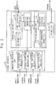
- Fig. 2 shows a configuration diagram of the control apparatus 100 related to the first embodiment.
- the control apparatus 100 includes a temperature measuring unit 110, a temperature memory unit 120, a control unit 130, and a temperature setting unit 140.
- the control unit is implemented as a central processing unit (CPU) including a RAM, ROM, etc.
- the temperature measuring unit 110 measures or obtains various kinds of temperatures.
- the temperature measuring unit 110 includes a supply temperature measuring unit 111, an outdoor temperature measuring unit 112, an indoor temperature measuring unit 113, and a preset temperature obtaining unit 114.
- the supply temperature measuring unit 111 measures a supply temperature using the temperature sensor 101.
- the outdoor temperature measuring unit 112 measures an outdoor temperature using the temperature sensor 102.
- the indoor temperature measuring unit 113 measures an indoor temperature using the temperature sensor 103.
- the preset temperature obtaining unit 114 obtains a preset temperature input by the remote controller 70.
- the temperature memory unit 120 is a memory device storing temperatures being necessary for control by the control unit 130.
- the temperature memory unit 120 includes a target temperature memory unit 121 and a restrictive temperature memory unit 122.
- the target temperature memory unit 121 is a memory device for storing the target temperature.
- the target temperature is, for instance, a predetermined temperature prescribed at the time of installing the heat pump system 200 and so on. Or, the target temperature can be calculated and set according to the heating load.
- the restrictive temperature memory unit 122 is a memory device storing a temperature being higher than the target temperature as an upper restrictive temperature, and a temperature being lower than the target temperature as a lower restrictive temperature.
- the upper restrictive temperature is set by a restrictive temperature setting unit 143 which will be discussed later, and for the lower restrictive temperature, a temperature which is lower than the target temperature with a predetermined degrees (2 degrees Celsius, for instance) is previously set.
- the control unit 130 controls the heat pump apparatus 10 so that the supply temperature should become the target temperature stored in the target temperature memory unit 121. Specifically, the control unit 130 controls an operating frequency of the compressor 1 to stay between a lower limit frequency and an upper limit frequency which have been previously set, so that the supply temperature should become the target temperature, and thereby the control unit 130 operates the compressor 1. For instance, the control unit 130, if a supply temperature difference between the target temperature and the supply temperature is large, sets the operating frequency of the compressor 1 high. On the other hand, the control unit 130 sets the operating frequency of the compressor 1 low if the supply temperature difference is small.
- control unit 130 stops the compressor 1 when the supply temperature is higher than the upper restrictive temperature; and after the compressor 1 stops, when the supply temperature becomes lower than the lower restrictive temperature, the control unit 130 restarts the compressor 1.
- control unit 130 sets the auxiliary heat source 20 to ON so that the supply temperature should become the target temperature.
- the temperature setting unit 140 sets the restrictive temperature in the restrictive temperature memory unit 122.
- the temperature setting unit 140 includes a COP memory unit 141, a limit temperature inputting unit 142, and a restrictive temperature setting unit 143.
- the COP memory unit 141 is a memory device storing values of a COP (Coefficient Of Performance) of the heat pump apparatus 10 of cases in which the outdoor temperature and the supply temperature are respectively changed.
- the limit temperature inputting unit 142 makes a user input the limit temperature which is an upper limit of the supply temperature using the remote controller 70, etc. at the time of installing the heat pump system 200 and so on.
- the upper limit of the supply temperature for instance, 40 degrees Celsius is input when the floor heating is used as the heating appliance and when the temperature being higher than 40 degrees Celsius may break the floor.
- the restrictive temperature setting unit 143 determines temperatures A, B, and C based on the following respective rules A to C.
- the restrictive temperature setting unit 143 sets the lowest temperature among the temperatures A, B, and C, which have been determined based on the respective rules, to the upper restrictive temperature.
- the restrictive temperature setting unit 143 determines a temperature by which COP stored in the COP memory unit 141 becomes a predetermined value (3, for instance) as the temperature A.
- the COP memory unit 141 stores COPs of cases in which the outdoor temperature and the supply temperature are respectively changed. Therefore, the restrictive temperature setting unit 143, at the outdoor temperature measured by the outdoor temperature measuring unit 112, obtains a supply temperature by which the COP becomes the predetermined value, and sets the supply temperature to the temperature A.
- the restrictive temperature setting unit 143 previously stores the temperature B with respect to the preset temperature difference, or stores a calculation formula for calculating the temperature B from the preset temperature difference. Then, the restrictive temperature setting unit 143 determines the temperature B based on the preset temperature difference and the stored information.
- the correlation between the operation status of the heat pump apparatus and the indoor temperature is small. Accordingly, when the preset temperature difference is large, the increase of the supply temperature does not instantly cause the indoor temperature to reach the preset temperature. Therefore, the upper restrictive temperature can be set high. On the other hand, when the preset temperature difference is small, the increase of the supply temperature may cause the indoor temperature to reach the preset temperature. Therefore, the upper restrictive temperature cannot be set high.
- the restrictive temperature setting unit 143 treats a limit temperature which the limit temperature inputting unit 142 makes the user input as the temperature C.
- Fig. 3 is a flowchart showing a flow of a control process of the control apparatus 100 related to the first embodiment.
- the temperature measuring unit 110 measures each temperature.
- the temperature setting unit 140 sets the upper restrictive temperature using each temperature measured or obtained at S1 in the restrictive temperature memory unit 122 in the above-discussed manner.
- the control unit 130 controls the compressor 1 provided at the heat pump apparatus 10 using each temperature measured or obtained at S1, so that the supply temperature should become the target temperature stored in the target temperature memory unit 121.
- control unit 130 stops the compressor 1 when the supply temperature becomes higher than the upper restrictive temperature stored in the restrictive temperature setting unit 143; and after stopping the compressor 1, when the supply temperature becomes lower than the lower restrictive temperature, the control unit 130 restarts the compressor 1.
- the upper restrictive temperature should be set as high as possible based on the COP, the preset temperature difference and so on. By this operation, it takes time before the supply temperature exceeds the upper restrictive temperature, and thus the number of times of stopping the compressor can be reduced.
- the heat pump system 200 is on the premise of using the heating operation by the natural convection system, so that even if the supply temperature slightly exceeds the target temperature, the increase of the supply temperature does not instantly cause to increase the indoor temperature. Therefore, the indoor comfort is not degraded, either.
- the upper limit frequency and the lower limit frequency which have been explained in the above are determined at the time of shipping the product and so on according to the features of the compressor 1 or the heat pump apparatus 10.
- rules of Rule A to Rule C are used to determine the upper restrictive temperature.
- the rules can be, for instance, only Rules A and B, or Rules A and C. Further, if the supply temperature would never exceed the temperature of Rule A, the rules can be Rules B and C, only Rule B, or only Rule C.
- 1 a compressor; 2: a heat exchanger; 3: an expansion mechanism; 4: a heat exchanger; 5: a refrigerant piping; 10: a heat pump apparatus; 20: an auxiliary heat source; 30 a heating appliance; 40: a pump; 50: a fluid piping; 60: an indoor space; 70: a remote controller; 100 a control apparatus; 101, 102, 103: temperature sensors; 110: a temperature measuring unit; 111: a supply temperature measuring unit; 112: an outdoor temperature measuring unit; 113: an indoor temperature measuring unit; 114: a preset temperature obtaining unit; 120: a temperature memory unit; 121: a target temperature memory unit; 122: a restrictive temperature memory unit; 130: a control unit; 140: a temperature setting unit; 141: a COP memory unit; 142: a limit temperature inputting unit, 143: a restrictive temperature setting unit; and 200: a heat pump system.
Description
- The present invention relates to a control technique of a compressor provided in a heat pump system. In particular, the present invention relates to a control technique of the compressor when its load is relatively low such as an intermediate season and so on.
- A heat pump type heating system is a system in which a heat pump apparatus generates heated water, the heated water is supplied to a heating appliance such as a floor heating system, a panel heater, and so on, and heating operation is carried out by radiation heat of the heating appliance.
- In the heat pump type heating system, the heat pump apparatus is controlled so that the temperature of the heated water (supply temperature) to be supplied to the heating appliance should become a target temperature which has been previously set.
- In the heat pump type heating system, fully utilizing the feature of inverter control of the heat pump apparatus, it is important for promoting energy saving to continuously operate the heat pump apparatus as long as possible within a range not to degrade the indoor comfort.
- However, when the performance of the heat pump apparatus is high with respect to the load, even if the heat pump apparatus is driven with the lowest possible performance, a supply temperature exceeds the target temperature at once. In this case, the following operation is repeated: when the supply temperature becomes higher than an upper restrictive temperature which is set a little higher than the target temperature, the operation of the heat pump apparatus temporarily stops, and when the supply temperature becomes a lower restrictive temperature which is set a little lower than the target temperature, the operation of the heat pump apparatus restarts again. Namely, the heat pump apparatus cannot operate continuously, which is not preferable to promote energy saving.
- Patent Literature 1 describes that the number of stops of the heat pump apparatus is measured, when the number of stops is large, it is determined that the load is low, and the target temperature is decreased.
- In Patent Literature 1, when the number of stops is large, the target temperature is lowered, thereby enabling the operation with decreasing the performance of the heat pump apparatus, which increases the operating efficiency. Further, by operating the heat pump apparatus with decreasing the performance, it takes time before the supply temperature reaches the target temperature, which reduces the number of stops of the heat pump apparatus.
- Patent Literature 1:
JP 2002 061 925 A - The method described in Patent Literature 1 can be used when the performance of the heat pump apparatus can be decreased; while the method cannot be used when the heat pump apparatus is operated with suppressing the performance of heat pump apparatus as much as possible.
- Further, Patent Literature 1 is on the premise of the air-conditioning operation by the forced convection system using a fan. Therefore, in Patent Literature 1, the feature of the heating operation of the natural convection system using the radiation heat of the heating appliance is not considered.
- In the forced convection system, there is a feature that the correlation between the operation status of the heat pump apparatus and the indoor temperature is large. On the contrary to this, in the natural convection system, the correlation between the operation status of the heat pump apparatus and the indoor temperature is small. Namely, in the forced convection system, when the performance of heat pump apparatus is increased, the indoor temperature is increased at once, and when the performance is decreased, the indoor temperature is decreased at once. However, in the natural convection system, even if the performance of heat pump apparatus is changed and the supply temperature is changed, it takes time before the indoor temperature is changed.
- The present invention aims, in the heat pump system using the heating appliance of the natural convection system, to reduce the number of stops of a compressor provided at the heat pump apparatus.
- According to the present invention, a heat pump system according to claim 1 and a method of a heat pump apparatus according to claim 4 are provided.
- In the heat pump system related to the present invention, instead of setting the restrictive temperature a little higher than the target temperature, the restrictive temperature is set higher than usual based on a COP. By this operation, it takes time before the supply temperature exceeds the restrictive temperature; as a result, the number of stops of the compressor is reduced.
- Here, since the heat pump system related to the present invention is on the premise of using the heating operation by the natural convection system, even if the supply temperature becomes a little higher than the target temperature, the indoor temperature is not increased at once. Therefore, the indoor comfort is not degraded.
- An embodiment of the present invention will become fully understood from the detailed description given hereinafter in conjunction with the accompanying drawings, in which:
-
Fig. 1 shows a configuration diagram of aheat pump system 200 related to the first embodiment. -
Fig. 2 shows a configuration diagram of acontrol apparatus 100 related to the first embodiment. -
Fig. 3 is a flowchart showing a flow of a control process of thecontrol apparatus 100 related to the first embodiment. - In describing preferred embodiments illustrated in the drawings, specific terminology is employed for the sake of clarity However, the disclosure of the present invention is not intended to be limited to the specific terminology so selected, and it is to be understood that each specific element includes all technical equivalents that operate in a similar manner and achieve a similar result.
-
Fig. 1 shows a configuration diagram of aheat pump system 200 related to the first embodiment. - The
heat pump system 200 includes aheat pump apparatus 10, anauxiliary heat source 20, aheating appliance 30 provided in anindoor space 60, and apump 40, which are connected in order by afluid piping 50. Here, thefluid piping 50 is connected to a heat exchanger 2 provided at theheat pump apparatus 10. Further, water (an example of fluid) flows inside thefluid piping 50. - In addition, a
remote controller 70 is provided at theindoor space 60 at which theheating appliance 30 is installed for inputting a preset temperature and so on. - The
heat pump apparatus 10 includes a heat pump cycle in which a compressor 1, a heat exchanger 2, an expansion mechanism 3, and a heat exchanger 4 are connected in order by arefrigerant piping 5. Refrigerant circulates within the heat pump cycle sequentially in an order of the compressor 1, the heat exchanger 2, the expansion mechanism 3, and the heat exchanger 4, and thereby the refrigerant absorbs heat from air, etc. at the heat exchanger 4 and discharges the heat to the water flowing through thefluid piping 50 at the heat exchanger 2. Namely, the water flowing through thefluid piping 50 is heated by theheat pump apparatus 10 to become heated water. - The
auxiliary heat source 20 further heats the heated water heated by theheat pump apparatus 10. Theauxiliary heat source 20 is, for instance, an electric heater and so on. - The
heating appliance 30 discharges the heat of the heated water heated by theheat pump apparatus 10 and theauxiliary heat source 20 to the air in theindoor space 60. As a result, it becomes warm inside theindoor space 60, and the heated water is cooled to become cool water. Theheating appliance 30 is such as a floor heating panel, a panel heater and so on which carry out heat exchange of the heated water with air by the natural convention system using the radiation heat. - The
pump 40 circulates water within thefluid piping 50. Namely, as thepump 40 works, the water circulates from theheat pump apparatus 10, theauxiliary heat source 20, and theheating appliance 30, in order. Then, as discussed above, the operation is repeated in which the water is heated at theheat pump apparatus 10, further heated by theauxiliary heat source 20, and cooled by theheating appliance 30. With this operation, theindoor space 60 is heated. - Further, the
heat pump system 200 includestemperature sensors 101 to 103. - The
temperature sensor 101 measures the temperature of water supplied to theheating appliance 30 as a supply temperature. Thetemperature sensor 102 measures an outdoor temperature. Thetemperature sensor 103 measures the temperature of air of theindoor space 60 as an indoor temperature. - In addition, the
heat pump system 200 includes acontrol apparatus 100 configured by micro-computer and so on. - The
control apparatus 100 obtains the temperatures measured by thetemperature sensors 101 to 103 and a preset temperature and so on inputted by theremote controller 70. Thecontrol apparatus 100 controls theheat pump apparatus 10 based on the obtained information, so that the temperature of the water supplied to theheating appliance 30 should become a target temperature. Further, thecontrol apparatus 100 controls ON/OFF of theauxiliary heat source 20 and ON/OFF of thepump 40 based on the obtained information. -
Fig. 2 shows a configuration diagram of thecontrol apparatus 100 related to the first embodiment. - The
control apparatus 100 includes atemperature measuring unit 110, atemperature memory unit 120, acontrol unit 130, and atemperature setting unit 140. The control unit is implemented as a central processing unit (CPU) including a RAM, ROM, etc. - The
temperature measuring unit 110 measures or obtains various kinds of temperatures. Thetemperature measuring unit 110 includes a supplytemperature measuring unit 111, an outdoortemperature measuring unit 112, an indoortemperature measuring unit 113, and a presettemperature obtaining unit 114. - The supply
temperature measuring unit 111 measures a supply temperature using thetemperature sensor 101. The outdoortemperature measuring unit 112 measures an outdoor temperature using thetemperature sensor 102. The indoortemperature measuring unit 113 measures an indoor temperature using thetemperature sensor 103. The presettemperature obtaining unit 114 obtains a preset temperature input by theremote controller 70. - The
temperature memory unit 120 is a memory device storing temperatures being necessary for control by thecontrol unit 130. Thetemperature memory unit 120 includes a targettemperature memory unit 121 and a restrictivetemperature memory unit 122. - The target
temperature memory unit 121 is a memory device for storing the target temperature. The target temperature is, for instance, a predetermined temperature prescribed at the time of installing theheat pump system 200 and so on. Or, the target temperature can be calculated and set according to the heating load. - The restrictive
temperature memory unit 122 is a memory device storing a temperature being higher than the target temperature as an upper restrictive temperature, and a temperature being lower than the target temperature as a lower restrictive temperature. Here, the upper restrictive temperature is set by a restrictivetemperature setting unit 143 which will be discussed later, and for the lower restrictive temperature, a temperature which is lower than the target temperature with a predetermined degrees (2 degrees Celsius, for instance) is previously set. - The
control unit 130 controls theheat pump apparatus 10 so that the supply temperature should become the target temperature stored in the targettemperature memory unit 121. Specifically, thecontrol unit 130 controls an operating frequency of the compressor 1 to stay between a lower limit frequency and an upper limit frequency which have been previously set, so that the supply temperature should become the target temperature, and thereby thecontrol unit 130 operates the compressor 1. For instance, thecontrol unit 130, if a supply temperature difference between the target temperature and the supply temperature is large, sets the operating frequency of the compressor 1 high. On the other hand, thecontrol unit 130 sets the operating frequency of the compressor 1 low if the supply temperature difference is small. - Further, the
control unit 130 stops the compressor 1 when the supply temperature is higher than the upper restrictive temperature; and after the compressor 1 stops, when the supply temperature becomes lower than the lower restrictive temperature, thecontrol unit 130 restarts the compressor 1. - Here, if the heat quantity is not sufficient using only the
heat pump apparatus 10, thecontrol unit 130 sets theauxiliary heat source 20 to ON so that the supply temperature should become the target temperature. - The
temperature setting unit 140 sets the restrictive temperature in the restrictivetemperature memory unit 122. Thetemperature setting unit 140 includes aCOP memory unit 141, a limittemperature inputting unit 142, and a restrictivetemperature setting unit 143. - The
COP memory unit 141 is a memory device storing values of a COP (Coefficient Of Performance) of theheat pump apparatus 10 of cases in which the outdoor temperature and the supply temperature are respectively changed. - Here, as a general rule, the higher the outdoor temperature becomes, the more COP increases; the higher the supply temperature becomes, the more the COP decreases.
- The limit
temperature inputting unit 142 makes a user input the limit temperature which is an upper limit of the supply temperature using theremote controller 70, etc. at the time of installing theheat pump system 200 and so on. - As for the upper limit of the supply temperature, for instance, 40 degrees Celsius is input when the floor heating is used as the heating appliance and when the temperature being higher than 40 degrees Celsius may break the floor.
- The restrictive
temperature setting unit 143 determines temperatures A, B, and C based on the following respective rules A to C. The restrictivetemperature setting unit 143 sets the lowest temperature among the temperatures A, B, and C, which have been determined based on the respective rules, to the upper restrictive temperature. - The restrictive
temperature setting unit 143 determines a temperature by which COP stored in theCOP memory unit 141 becomes a predetermined value (3, for instance) as the temperature A. TheCOP memory unit 141 stores COPs of cases in which the outdoor temperature and the supply temperature are respectively changed. Therefore, the restrictivetemperature setting unit 143, at the outdoor temperature measured by the outdoortemperature measuring unit 112, obtains a supply temperature by which the COP becomes the predetermined value, and sets the supply temperature to the temperature A. - This is to prevent a case in which the heat pump apparatus is continuously operated in exchange of decreasing the COP largely, resulting in the opposite effect of degraded efficiency
- The smaller a preset temperature difference, which is a difference between the indoor temperature measured by the indoor
temperature measuring unit 113 and the preset temperature obtained by the presettemperature obtaining unit 114, the lower the restrictivetemperature setting unit 143 determines the temperature B. For instance, the restrictivetemperature setting unit 143 previously stores the temperature B with respect to the preset temperature difference, or stores a calculation formula for calculating the temperature B from the preset temperature difference. Then, the restrictivetemperature setting unit 143 determines the temperature B based on the preset temperature difference and the stored information. - This is so as not to degrade the indoor comfort. As discussed above, in the natural convection system, the correlation between the operation status of the heat pump apparatus and the indoor temperature is small. Accordingly, when the preset temperature difference is large, the increase of the supply temperature does not instantly cause the indoor temperature to reach the preset temperature. Therefore, the upper restrictive temperature can be set high. On the other hand, when the preset temperature difference is small, the increase of the supply temperature may cause the indoor temperature to reach the preset temperature. Therefore, the upper restrictive temperature cannot be set high.
- The restrictive
temperature setting unit 143 treats a limit temperature which the limittemperature inputting unit 142 makes the user input as the temperature C. - This is to prevent a case in which a temperature being higher than the limit temperature is set as the upper restrictive temperature, and the supply temperature may exceed the limit temperature.
-
Fig. 3 is a flowchart showing a flow of a control process of thecontrol apparatus 100 related to the first embodiment. - The
temperature measuring unit 110 measures each temperature. - The
temperature setting unit 140 sets the upper restrictive temperature using each temperature measured or obtained at S1 in the restrictivetemperature memory unit 122 in the above-discussed manner. - The
control unit 130 controls the compressor 1 provided at theheat pump apparatus 10 using each temperature measured or obtained at S1, so that the supply temperature should become the target temperature stored in the targettemperature memory unit 121. - At this time, the
control unit 130 stops the compressor 1 when the supply temperature becomes higher than the upper restrictive temperature stored in the restrictivetemperature setting unit 143; and after stopping the compressor 1, when the supply temperature becomes lower than the lower restrictive temperature, thecontrol unit 130 restarts the compressor 1. - After a predetermined time has passed, the process will start from S1 again.
- As discussed above, in the
heat pump system 200 related to the first embodiment, the upper restrictive temperature should be set as high as possible based on the COP, the preset temperature difference and so on. By this operation, it takes time before the supply temperature exceeds the upper restrictive temperature, and thus the number of times of stopping the compressor can be reduced. - Here, the
heat pump system 200 is on the premise of using the heating operation by the natural convection system, so that even if the supply temperature slightly exceeds the target temperature, the increase of the supply temperature does not instantly cause to increase the indoor temperature. Therefore, the indoor comfort is not degraded, either. - Here, the upper limit frequency and the lower limit frequency which have been explained in the above are determined at the time of shipping the product and so on according to the features of the compressor 1 or the
heat pump apparatus 10. - Further, in the above explanation, three rules of Rule A to Rule C are used to determine the upper restrictive temperature. However, the rules can be, for instance, only Rules A and B, or Rules A and C. Further, if the supply temperature would never exceed the temperature of Rule A, the rules can be Rules B and C, only Rule B, or only Rule C.
- Numerous additional modifications and variations are possible in light of the above teachings. It is therefore to be understood that, within the scope of the appended claims, the disclosure of this patent specification may be practiced otherwise than as specifically described herein.
- 1: a compressor; 2: a heat exchanger; 3: an expansion mechanism; 4: a heat exchanger; 5: a refrigerant piping; 10: a heat pump apparatus; 20: an auxiliary heat source; 30 a heating appliance; 40: a pump; 50: a fluid piping; 60: an indoor space; 70: a remote controller; 100 a control apparatus; 101, 102, 103: temperature sensors; 110: a temperature measuring unit; 111: a supply temperature measuring unit; 112: an outdoor temperature measuring unit; 113: an indoor temperature measuring unit; 114: a preset temperature obtaining unit; 120: a temperature memory unit; 121: a target temperature memory unit; 122: a restrictive temperature memory unit; 130: a control unit; 140: a temperature setting unit; 141: a COP memory unit; 142: a limit temperature inputting unit, 143: a restrictive temperature setting unit; and 200: a heat pump system.
Claims (4)
- A heat pump system (200) including a heat pump apparatus (10) having a compressor (1), for supplying fluid heated by the heat pump apparatus to a heating appliance (30), the heat pump system comprising:an outdoor temperature measuring unit (112) for measuring an outdoor temperature;a supply temperature measuring unit (111) for measuring a temperature of the fluid to be supplied to the heating appliance as a supply temperature; characterized in that the heating appliance carries out heat exchange of the fluid with air by natural convection, andin that the heat pump system comprises a COP memory unit (141) for storing values of a COP (Coefficient Of Performance) of cases in which the outdoor temperature and the supply temperature are respectively changed, wherein the value of COP is associated with the outdoor temperature and the supply temperature, whereby as a general rule the higher the outdoor temperature becomes, the more the value of COP increases, and the higher the supply temperature becomes, the more the value of COP decreases;a restrictive temperature setting unit (143) for setting a temperature A as an upper restrictive temperature which is higher than a preset target temperature and which corresponds to a supply temperature for which the COP stored by the COP memory unit has a predetermined value with respect to the outdoor temperature measured by the outdoor temperature measuring unit, anda control unit (130) comprising a processor and for controlling an operating frequency of the compressor, so that the supply temperature measured by the supply temperature measuring unit should become the target temperature , and for temporarily stopping the compressor when the supply temperature becomes the upper restrictive temperature set by the restrictive temperature setting unit.
- The heat pump system of claim 1,wherein the heat pump system further comprises:an indoor temperature measuring unit (113) for measuring a temperature of a room at which the heating appliance is provided as an indoor temperature; anda preset temperature obtaining unit (114) for obtaining a preset temperature of the room set by a user, andwherein the restrictive temperature setting unit sets whichever is lower between the temperature A and a temperature B as the restrictive temperature when the smaller a difference between the indoor temperature measured by the indoor temperature measuring unit and the preset temperature obtained by the preset temperature obtaining unit, the lower the restrictive temperature setting unit determines the temperature B.
- The heat pump system of claim 2,wherein the heat pump system further comprises a limit temperature inputting unit (142) for making a user input the limit temperature, and wherein the restrictive temperature setting unit sets whichever is lowest among the temperature A, the temperature B, and a temperature C as the restrictive temperature when the limit temperature made to input by the limit temperature inputting unit is assumed as the temperature C.
- A control method of a heat pump apparatus (10) of a heat pump system (200) including the heat pump apparatus having a compressor (1), for supplying fluid heated by the heat pump apparatus to a heating appliance (30) which carries out heat exchange of the fluid with air by natural convection, the control method comprising:by a temperature sensor (102), an outdoor temperature measuring process for measuring an outdoor temperature;by a temperature sensor (101), a supply temperature measuring process for measuring a temperature of the fluid to be supplied to the heating appliance as a supply temperature;by a control apparatus (100), a restrictive temperature setting process for reading, from a memory device for storing values of a COP (Coefficient Of Performance) of cases in which the outdoor temperature and the supply temperature are respectively changed, wherein the value of COP is associated with the outdoor temperature and the supply temperature, whereby as a general rule the higher the outdoor temperature becomes, the more the value of COP increases and the higher the supply temperature becomes, the more the value of COP decreases, a supply temperature by which the stored COP becomes a predetermined value with respect to the outdoor temperature measured by the outdoor temperature measuring process as a temperature A, and setting the temperature A as an upper restrictive temperature which is higher than a preset target temperature and which corresponds to a supply temperature for which the COP stored by the memory device has a predetermined value with respect to the measured outdoor temperature, andby the control apparatus, a controlling process for controlling an operating frequency of the compressor, so that the supply temperature measured by the supply temperature measuring process should become a target temperature, and for temporarily stopping the compressor when the supply temperature becomes the upper restrictive temperature set by the restrictive temperature setting process.
Applications Claiming Priority (1)
| Application Number | Priority Date | Filing Date | Title |
|---|---|---|---|
| JP2011290349A JP5452581B2 (en) | 2011-12-29 | 2011-12-29 | HEAT PUMP SYSTEM AND HEAT PUMP DEVICE CONTROL METHOD |
Publications (3)
| Publication Number | Publication Date |
|---|---|
| EP2610558A2 EP2610558A2 (en) | 2013-07-03 |
| EP2610558A3 EP2610558A3 (en) | 2015-10-14 |
| EP2610558B1 true EP2610558B1 (en) | 2017-09-27 |
Family
ID=46754893
Family Applications (1)
| Application Number | Title | Priority Date | Filing Date |
|---|---|---|---|
| EP12179961.3A Not-in-force EP2610558B1 (en) | 2011-12-29 | 2012-08-09 | Heat pump system and control method of heat pump apparatus of heat pump system |
Country Status (3)
| Country | Link |
|---|---|
| EP (1) | EP2610558B1 (en) |
| JP (1) | JP5452581B2 (en) |
| CN (1) | CN103185420B (en) |
Families Citing this family (12)
| Publication number | Priority date | Publication date | Assignee | Title |
|---|---|---|---|---|
| CN104566840B (en) * | 2013-10-16 | 2018-04-27 | 海尔集团公司 | Refrigerant radiator, the air-conditioning and temprature control method for installing it |
| JP5984784B2 (en) * | 2013-11-19 | 2016-09-06 | 三菱電機株式会社 | Hot / cold water air conditioning system |
| CN104006592B (en) * | 2014-06-05 | 2016-08-24 | 珠海格力电器股份有限公司 | The frequency adjustment method of frequency-changeable compressor and device in heat pump |
| CN105444419B (en) * | 2014-08-18 | 2018-02-09 | 珠海格力电器股份有限公司 | The method and device of the compressor frequency control of air-source water heater |
| JP6385446B2 (en) * | 2014-09-01 | 2018-09-05 | 三菱電機株式会社 | Air conditioning system control apparatus and air conditioning system control method |
| ES2744776T3 (en) | 2015-03-09 | 2020-02-26 | Daikin Ind Ltd | Air conditioning control device |
| EP3270072B1 (en) * | 2015-03-09 | 2019-02-20 | Daikin Industries, Ltd. | Air conditioning control device |
| JP6550959B2 (en) * | 2015-06-22 | 2019-07-31 | 三菱電機株式会社 | Heat transfer system |
| CN105509316A (en) * | 2016-01-11 | 2016-04-20 | 佛山市顺德区爱尼电器制造有限公司 | Control method and system for heat-pump water heater |
| JP6613192B2 (en) * | 2016-03-29 | 2019-11-27 | 東芝キヤリア株式会社 | Heat pump type heat source device |
| CN109268924B (en) * | 2018-08-23 | 2020-01-10 | 珠海格力电器股份有限公司 | Method for controlling on-off number of heat pump units and heat pump unit system |
| DE102020215669A1 (en) | 2020-12-10 | 2022-06-15 | Viessmann Climate Solutions Se | METHOD OF OPERATING A HEAT PUMP |
Family Cites Families (12)
| Publication number | Priority date | Publication date | Assignee | Title |
|---|---|---|---|---|
| DE2702489C2 (en) * | 1977-01-21 | 1984-02-09 | Heinz Dipl.-Ing. 7951 Erlenmoos Gerbert | Method and device for automatically optimizing the operating point of a heat pump |
| JP2002061925A (en) | 2000-08-23 | 2002-02-28 | Daikin Ind Ltd | Air conditioner |
| CN100535542C (en) * | 2002-02-12 | 2009-09-02 | 松下电器产业株式会社 | Heat-pump water heater |
| WO2006006578A1 (en) * | 2004-07-12 | 2006-01-19 | Denso Corporation | Heat pump-type hot-water supply device |
| JP3904013B2 (en) * | 2004-10-25 | 2007-04-11 | 松下電器産業株式会社 | Heat pump type water heater |
| JP5073970B2 (en) * | 2006-06-01 | 2012-11-14 | 日立アプライアンス株式会社 | Heat pump hot water floor heater |
| JP2009162458A (en) * | 2008-01-10 | 2009-07-23 | Hitachi Appliances Inc | Heat pump hot water supply system |
| JP5481838B2 (en) * | 2008-11-10 | 2014-04-23 | 株式会社デンソー | Heat pump cycle equipment |
| JP2011094810A (en) * | 2009-09-30 | 2011-05-12 | Fujitsu General Ltd | Heat pump cycle apparatus |
| JP5334905B2 (en) * | 2010-03-31 | 2013-11-06 | 三菱電機株式会社 | Refrigeration cycle equipment |
| EP2559953B1 (en) * | 2010-04-15 | 2016-09-28 | Mitsubishi Electric Corporation | Hot water supply system and method for operating the system |
| DE102010024986A1 (en) * | 2010-06-24 | 2011-12-29 | Stiebel Eltron Gmbh & Co. Kg | Method for controlling a heat pump unit and heat pump unit |
-
2011
- 2011-12-29 JP JP2011290349A patent/JP5452581B2/en not_active Expired - Fee Related
-
2012
- 2012-08-09 EP EP12179961.3A patent/EP2610558B1/en not_active Not-in-force
- 2012-08-10 CN CN201210285365.4A patent/CN103185420B/en active Active
Non-Patent Citations (1)
| Title |
|---|
| None * |
Also Published As
| Publication number | Publication date |
|---|---|
| JP5452581B2 (en) | 2014-03-26 |
| EP2610558A3 (en) | 2015-10-14 |
| EP2610558A2 (en) | 2013-07-03 |
| CN103185420B (en) | 2015-04-29 |
| JP2013139954A (en) | 2013-07-18 |
| CN103185420A (en) | 2013-07-03 |
Similar Documents
| Publication | Publication Date | Title |
|---|---|---|
| EP2610558B1 (en) | Heat pump system and control method of heat pump apparatus of heat pump system | |
| Corberan et al. | A quasi-steady state mathematical model of an integrated ground source heat pump for building space control | |
| US20160265794A1 (en) | Heat Pump Water Heater and Control Method Thereof | |
| JP5657110B2 (en) | Temperature control system and air conditioning system | |
| EP2508806B1 (en) | Heat pump system and heat pump unit controlling method | |
| JP6471672B2 (en) | Hot water heating system | |
| CN103047740A (en) | Method for reducing water flow of air conditioning system and dynamic temperature difference flow regulating valve | |
| CN107429930B (en) | Air conditioning system control device | |
| JP5973076B2 (en) | Hot water heater | |
| JP2008014585A (en) | Brine heat radiation type heating apparatus | |
| EP3159613B1 (en) | Heat pump heating system | |
| US20160238261A1 (en) | Control of a pump to optimize heat transfer | |
| EP3258185B1 (en) | Heat supply system | |
| EP2589883A2 (en) | Heat pump hydronic heater | |
| JP6078780B2 (en) | Heat pump hot water heater | |
| JP2007327727A (en) | Heat pump water heater | |
| KR20170012770A (en) | Heating system for hybrid vehicle and method for controlling the same | |
| US11674706B2 (en) | System and method for operating an air conditioner unit having an auxiliary electric heater | |
| WO2013001261A1 (en) | Fan convector heating unit | |
| JP2017067321A (en) | Heat pump control device, hot water supply unit of heat pump-type heating system, heat pump-type heating system, and method executed by heat pump control device | |
| JP7199529B2 (en) | Control device, air environment adjustment system, air environment adjustment method, program, and recording medium | |
| JP2014005961A (en) | Refrigeration cycle device and hot water generator including the same | |
| JP6851256B2 (en) | Floor heating system | |
| JP2011237111A (en) | Heat pump hot water heating apparatus | |
| KR20150122374A (en) | Method for saving power of an air conditioner and Air conditioner by using the method |
Legal Events
| Date | Code | Title | Description |
|---|---|---|---|
| PUAI | Public reference made under article 153(3) epc to a published international application that has entered the european phase |
Free format text: ORIGINAL CODE: 0009012 |
|
| AK | Designated contracting states |
Kind code of ref document: A2 Designated state(s): AL AT BE BG CH CY CZ DE DK EE ES FI FR GB GR HR HU IE IS IT LI LT LU LV MC MK MT NL NO PL PT RO RS SE SI SK SM TR |
|
| AX | Request for extension of the european patent |
Extension state: BA ME |
|
| PUAL | Search report despatched |
Free format text: ORIGINAL CODE: 0009013 |
|
| AK | Designated contracting states |
Kind code of ref document: A3 Designated state(s): AL AT BE BG CH CY CZ DE DK EE ES FI FR GB GR HR HU IE IS IT LI LT LU LV MC MK MT NL NO PL PT RO RS SE SI SK SM TR |
|
| AX | Request for extension of the european patent |
Extension state: BA ME |
|
| RIC1 | Information provided on ipc code assigned before grant |
Ipc: F24D 3/18 20060101AFI20150909BHEP Ipc: F24D 19/10 20060101ALI20150909BHEP |
|
| 17P | Request for examination filed |
Effective date: 20160407 |
|
| RBV | Designated contracting states (corrected) |
Designated state(s): AL AT BE BG CH CY CZ DE DK EE ES FI FR GB GR HR HU IE IS IT LI LT LU LV MC MK MT NL NO PL PT RO RS SE SI SK SM TR |
|
| 17Q | First examination report despatched |
Effective date: 20161024 |
|
| GRAP | Despatch of communication of intention to grant a patent |
Free format text: ORIGINAL CODE: EPIDOSNIGR1 |
|
| INTG | Intention to grant announced |
Effective date: 20170406 |
|
| GRAS | Grant fee paid |
Free format text: ORIGINAL CODE: EPIDOSNIGR3 |
|
| GRAA | (expected) grant |
Free format text: ORIGINAL CODE: 0009210 |
|
| AK | Designated contracting states |
Kind code of ref document: B1 Designated state(s): AL AT BE BG CH CY CZ DE DK EE ES FI FR GB GR HR HU IE IS IT LI LT LU LV MC MK MT NL NO PL PT RO RS SE SI SK SM TR |
|
| REG | Reference to a national code |
Ref country code: GB Ref legal event code: FG4D |
|
| REG | Reference to a national code |
Ref country code: CH Ref legal event code: EP |
|
| REG | Reference to a national code |
Ref country code: AT Ref legal event code: REF Ref document number: 932316 Country of ref document: AT Kind code of ref document: T Effective date: 20171015 |
|
| REG | Reference to a national code |
Ref country code: IE Ref legal event code: FG4D |
|
| REG | Reference to a national code |
Ref country code: SE Ref legal event code: TRGR |
|
| REG | Reference to a national code |
Ref country code: DE Ref legal event code: R096 Ref document number: 602012037731 Country of ref document: DE |
|
| PG25 | Lapsed in a contracting state [announced via postgrant information from national office to epo] |
Ref country code: HR Free format text: LAPSE BECAUSE OF FAILURE TO SUBMIT A TRANSLATION OF THE DESCRIPTION OR TO PAY THE FEE WITHIN THE PRESCRIBED TIME-LIMIT Effective date: 20170927 Ref country code: LT Free format text: LAPSE BECAUSE OF FAILURE TO SUBMIT A TRANSLATION OF THE DESCRIPTION OR TO PAY THE FEE WITHIN THE PRESCRIBED TIME-LIMIT Effective date: 20170927 Ref country code: FI Free format text: LAPSE BECAUSE OF FAILURE TO SUBMIT A TRANSLATION OF THE DESCRIPTION OR TO PAY THE FEE WITHIN THE PRESCRIBED TIME-LIMIT Effective date: 20170927 Ref country code: NO Free format text: LAPSE BECAUSE OF FAILURE TO SUBMIT A TRANSLATION OF THE DESCRIPTION OR TO PAY THE FEE WITHIN THE PRESCRIBED TIME-LIMIT Effective date: 20171227 |
|
| REG | Reference to a national code |
Ref country code: NL Ref legal event code: MP Effective date: 20170927 |
|
| REG | Reference to a national code |
Ref country code: LT Ref legal event code: MG4D |
|
| REG | Reference to a national code |
Ref country code: AT Ref legal event code: MK05 Ref document number: 932316 Country of ref document: AT Kind code of ref document: T Effective date: 20170927 |
|
| PG25 | Lapsed in a contracting state [announced via postgrant information from national office to epo] |
Ref country code: GR Free format text: LAPSE BECAUSE OF FAILURE TO SUBMIT A TRANSLATION OF THE DESCRIPTION OR TO PAY THE FEE WITHIN THE PRESCRIBED TIME-LIMIT Effective date: 20171228 Ref country code: LV Free format text: LAPSE BECAUSE OF FAILURE TO SUBMIT A TRANSLATION OF THE DESCRIPTION OR TO PAY THE FEE WITHIN THE PRESCRIBED TIME-LIMIT Effective date: 20170927 Ref country code: RS Free format text: LAPSE BECAUSE OF FAILURE TO SUBMIT A TRANSLATION OF THE DESCRIPTION OR TO PAY THE FEE WITHIN THE PRESCRIBED TIME-LIMIT Effective date: 20170927 Ref country code: BG Free format text: LAPSE BECAUSE OF FAILURE TO SUBMIT A TRANSLATION OF THE DESCRIPTION OR TO PAY THE FEE WITHIN THE PRESCRIBED TIME-LIMIT Effective date: 20171227 |
|
| PG25 | Lapsed in a contracting state [announced via postgrant information from national office to epo] |
Ref country code: NL Free format text: LAPSE BECAUSE OF FAILURE TO SUBMIT A TRANSLATION OF THE DESCRIPTION OR TO PAY THE FEE WITHIN THE PRESCRIBED TIME-LIMIT Effective date: 20170927 |
|
| PG25 | Lapsed in a contracting state [announced via postgrant information from national office to epo] |
Ref country code: ES Free format text: LAPSE BECAUSE OF FAILURE TO SUBMIT A TRANSLATION OF THE DESCRIPTION OR TO PAY THE FEE WITHIN THE PRESCRIBED TIME-LIMIT Effective date: 20170927 Ref country code: RO Free format text: LAPSE BECAUSE OF FAILURE TO SUBMIT A TRANSLATION OF THE DESCRIPTION OR TO PAY THE FEE WITHIN THE PRESCRIBED TIME-LIMIT Effective date: 20170927 Ref country code: CZ Free format text: LAPSE BECAUSE OF FAILURE TO SUBMIT A TRANSLATION OF THE DESCRIPTION OR TO PAY THE FEE WITHIN THE PRESCRIBED TIME-LIMIT Effective date: 20170927 |
|
| PG25 | Lapsed in a contracting state [announced via postgrant information from national office to epo] |
Ref country code: SM Free format text: LAPSE BECAUSE OF FAILURE TO SUBMIT A TRANSLATION OF THE DESCRIPTION OR TO PAY THE FEE WITHIN THE PRESCRIBED TIME-LIMIT Effective date: 20170927 Ref country code: IS Free format text: LAPSE BECAUSE OF FAILURE TO SUBMIT A TRANSLATION OF THE DESCRIPTION OR TO PAY THE FEE WITHIN THE PRESCRIBED TIME-LIMIT Effective date: 20180127 Ref country code: EE Free format text: LAPSE BECAUSE OF FAILURE TO SUBMIT A TRANSLATION OF THE DESCRIPTION OR TO PAY THE FEE WITHIN THE PRESCRIBED TIME-LIMIT Effective date: 20170927 Ref country code: IT Free format text: LAPSE BECAUSE OF FAILURE TO SUBMIT A TRANSLATION OF THE DESCRIPTION OR TO PAY THE FEE WITHIN THE PRESCRIBED TIME-LIMIT Effective date: 20170927 Ref country code: AT Free format text: LAPSE BECAUSE OF FAILURE TO SUBMIT A TRANSLATION OF THE DESCRIPTION OR TO PAY THE FEE WITHIN THE PRESCRIBED TIME-LIMIT Effective date: 20170927 Ref country code: SK Free format text: LAPSE BECAUSE OF FAILURE TO SUBMIT A TRANSLATION OF THE DESCRIPTION OR TO PAY THE FEE WITHIN THE PRESCRIBED TIME-LIMIT Effective date: 20170927 |
|
| REG | Reference to a national code |
Ref country code: DE Ref legal event code: R097 Ref document number: 602012037731 Country of ref document: DE |
|
| REG | Reference to a national code |
Ref country code: FR Ref legal event code: PLFP Year of fee payment: 7 |
|
| PG25 | Lapsed in a contracting state [announced via postgrant information from national office to epo] |
Ref country code: DK Free format text: LAPSE BECAUSE OF FAILURE TO SUBMIT A TRANSLATION OF THE DESCRIPTION OR TO PAY THE FEE WITHIN THE PRESCRIBED TIME-LIMIT Effective date: 20170927 |
|
| PLBE | No opposition filed within time limit |
Free format text: ORIGINAL CODE: 0009261 |
|
| STAA | Information on the status of an ep patent application or granted ep patent |
Free format text: STATUS: NO OPPOSITION FILED WITHIN TIME LIMIT |
|
| PG25 | Lapsed in a contracting state [announced via postgrant information from national office to epo] |
Ref country code: PL Free format text: LAPSE BECAUSE OF FAILURE TO SUBMIT A TRANSLATION OF THE DESCRIPTION OR TO PAY THE FEE WITHIN THE PRESCRIBED TIME-LIMIT Effective date: 20170927 |
|
| 26N | No opposition filed |
Effective date: 20180628 |
|
| PG25 | Lapsed in a contracting state [announced via postgrant information from national office to epo] |
Ref country code: SI Free format text: LAPSE BECAUSE OF FAILURE TO SUBMIT A TRANSLATION OF THE DESCRIPTION OR TO PAY THE FEE WITHIN THE PRESCRIBED TIME-LIMIT Effective date: 20170927 |
|
| PG25 | Lapsed in a contracting state [announced via postgrant information from national office to epo] |
Ref country code: MC Free format text: LAPSE BECAUSE OF FAILURE TO SUBMIT A TRANSLATION OF THE DESCRIPTION OR TO PAY THE FEE WITHIN THE PRESCRIBED TIME-LIMIT Effective date: 20170927 |
|
| REG | Reference to a national code |
Ref country code: CH Ref legal event code: PL |
|
| PG25 | Lapsed in a contracting state [announced via postgrant information from national office to epo] |
Ref country code: CH Free format text: LAPSE BECAUSE OF NON-PAYMENT OF DUE FEES Effective date: 20180831 Ref country code: LI Free format text: LAPSE BECAUSE OF NON-PAYMENT OF DUE FEES Effective date: 20180831 Ref country code: LU Free format text: LAPSE BECAUSE OF NON-PAYMENT OF DUE FEES Effective date: 20180809 |
|
| REG | Reference to a national code |
Ref country code: BE Ref legal event code: MM Effective date: 20180831 |
|
| REG | Reference to a national code |
Ref country code: IE Ref legal event code: MM4A |
|
| PG25 | Lapsed in a contracting state [announced via postgrant information from national office to epo] |
Ref country code: IE Free format text: LAPSE BECAUSE OF NON-PAYMENT OF DUE FEES Effective date: 20180809 |
|
| PG25 | Lapsed in a contracting state [announced via postgrant information from national office to epo] |
Ref country code: BE Free format text: LAPSE BECAUSE OF NON-PAYMENT OF DUE FEES Effective date: 20180831 |
|
| PG25 | Lapsed in a contracting state [announced via postgrant information from national office to epo] |
Ref country code: MT Free format text: LAPSE BECAUSE OF NON-PAYMENT OF DUE FEES Effective date: 20180809 |
|
| PG25 | Lapsed in a contracting state [announced via postgrant information from national office to epo] |
Ref country code: TR Free format text: LAPSE BECAUSE OF FAILURE TO SUBMIT A TRANSLATION OF THE DESCRIPTION OR TO PAY THE FEE WITHIN THE PRESCRIBED TIME-LIMIT Effective date: 20170927 |
|
| PG25 | Lapsed in a contracting state [announced via postgrant information from national office to epo] |
Ref country code: HU Free format text: LAPSE BECAUSE OF FAILURE TO SUBMIT A TRANSLATION OF THE DESCRIPTION OR TO PAY THE FEE WITHIN THE PRESCRIBED TIME-LIMIT; INVALID AB INITIO Effective date: 20120809 Ref country code: PT Free format text: LAPSE BECAUSE OF FAILURE TO SUBMIT A TRANSLATION OF THE DESCRIPTION OR TO PAY THE FEE WITHIN THE PRESCRIBED TIME-LIMIT Effective date: 20170927 |
|
| PG25 | Lapsed in a contracting state [announced via postgrant information from national office to epo] |
Ref country code: MK Free format text: LAPSE BECAUSE OF NON-PAYMENT OF DUE FEES Effective date: 20170927 Ref country code: CY Free format text: LAPSE BECAUSE OF FAILURE TO SUBMIT A TRANSLATION OF THE DESCRIPTION OR TO PAY THE FEE WITHIN THE PRESCRIBED TIME-LIMIT Effective date: 20170927 |
|
| PG25 | Lapsed in a contracting state [announced via postgrant information from national office to epo] |
Ref country code: AL Free format text: LAPSE BECAUSE OF FAILURE TO SUBMIT A TRANSLATION OF THE DESCRIPTION OR TO PAY THE FEE WITHIN THE PRESCRIBED TIME-LIMIT Effective date: 20170927 |
|
| REG | Reference to a national code |
Ref country code: GB Ref legal event code: 746 Effective date: 20200908 |
|
| PGFP | Annual fee paid to national office [announced via postgrant information from national office to epo] |
Ref country code: FR Payment date: 20200715 Year of fee payment: 9 Ref country code: DE Payment date: 20200729 Year of fee payment: 9 Ref country code: GB Payment date: 20200729 Year of fee payment: 9 |
|
| REG | Reference to a national code |
Ref country code: DE Ref legal event code: R084 Ref document number: 602012037731 Country of ref document: DE |
|
| PGFP | Annual fee paid to national office [announced via postgrant information from national office to epo] |
Ref country code: SE Payment date: 20200811 Year of fee payment: 9 |
|
| REG | Reference to a national code |
Ref country code: DE Ref legal event code: R119 Ref document number: 602012037731 Country of ref document: DE |
|
| REG | Reference to a national code |
Ref country code: SE Ref legal event code: EUG |
|
| GBPC | Gb: european patent ceased through non-payment of renewal fee |
Effective date: 20210809 |
|
| PG25 | Lapsed in a contracting state [announced via postgrant information from national office to epo] |
Ref country code: SE Free format text: LAPSE BECAUSE OF NON-PAYMENT OF DUE FEES Effective date: 20210810 |
|
| PG25 | Lapsed in a contracting state [announced via postgrant information from national office to epo] |
Ref country code: GB Free format text: LAPSE BECAUSE OF NON-PAYMENT OF DUE FEES Effective date: 20210809 Ref country code: FR Free format text: LAPSE BECAUSE OF NON-PAYMENT OF DUE FEES Effective date: 20210831 Ref country code: DE Free format text: LAPSE BECAUSE OF NON-PAYMENT OF DUE FEES Effective date: 20220301 |