EP2610506A1 - Spring nut - Google Patents
Spring nut Download PDFInfo
- Publication number
- EP2610506A1 EP2610506A1 EP11010276.1A EP11010276A EP2610506A1 EP 2610506 A1 EP2610506 A1 EP 2610506A1 EP 11010276 A EP11010276 A EP 11010276A EP 2610506 A1 EP2610506 A1 EP 2610506A1
- Authority
- EP
- European Patent Office
- Prior art keywords
- bolt
- spring nut
- wall
- spring
- receptacle
- Prior art date
- Legal status (The legal status is an assumption and is not a legal conclusion. Google has not performed a legal analysis and makes no representation as to the accuracy of the status listed.)
- Granted
Links
- 238000003780 insertion Methods 0.000 claims abstract description 12
- 230000037431 insertion Effects 0.000 claims abstract description 12
- 230000002093 peripheral effect Effects 0.000 abstract 3
- 230000006978 adaptation Effects 0.000 description 2
- 238000001746 injection moulding Methods 0.000 description 2
- 238000004519 manufacturing process Methods 0.000 description 2
- 230000006835 compression Effects 0.000 description 1
- 238000007906 compression Methods 0.000 description 1
- 238000002347 injection Methods 0.000 description 1
- 239000007924 injection Substances 0.000 description 1
Images

Classifications
-
- F—MECHANICAL ENGINEERING; LIGHTING; HEATING; WEAPONS; BLASTING
- F16—ENGINEERING ELEMENTS AND UNITS; GENERAL MEASURES FOR PRODUCING AND MAINTAINING EFFECTIVE FUNCTIONING OF MACHINES OR INSTALLATIONS; THERMAL INSULATION IN GENERAL
- F16B—DEVICES FOR FASTENING OR SECURING CONSTRUCTIONAL ELEMENTS OR MACHINE PARTS TOGETHER, e.g. NAILS, BOLTS, CIRCLIPS, CLAMPS, CLIPS OR WEDGES; JOINTS OR JOINTING
- F16B37/00—Nuts or like thread-engaging members
- F16B37/08—Quickly-detachable or mountable nuts, e.g. consisting of two or more parts; Nuts movable along the bolt after tilting the nut
- F16B37/0807—Nuts engaged from the end of the bolt, e.g. axially slidable nuts
- F16B37/0842—Nuts engaged from the end of the bolt, e.g. axially slidable nuts fastened to the threaded bolt with snap-on-action, e.g. push-on nuts for stud bolts
-
- F—MECHANICAL ENGINEERING; LIGHTING; HEATING; WEAPONS; BLASTING
- F16—ENGINEERING ELEMENTS AND UNITS; GENERAL MEASURES FOR PRODUCING AND MAINTAINING EFFECTIVE FUNCTIONING OF MACHINES OR INSTALLATIONS; THERMAL INSULATION IN GENERAL
- F16B—DEVICES FOR FASTENING OR SECURING CONSTRUCTIONAL ELEMENTS OR MACHINE PARTS TOGETHER, e.g. NAILS, BOLTS, CIRCLIPS, CLAMPS, CLIPS OR WEDGES; JOINTS OR JOINTING
- F16B27/00—Bolts, screws, or nuts formed in integral series but easily separable, particularly for use in automatic machines
-
- F—MECHANICAL ENGINEERING; LIGHTING; HEATING; WEAPONS; BLASTING
- F16—ENGINEERING ELEMENTS AND UNITS; GENERAL MEASURES FOR PRODUCING AND MAINTAINING EFFECTIVE FUNCTIONING OF MACHINES OR INSTALLATIONS; THERMAL INSULATION IN GENERAL
- F16B—DEVICES FOR FASTENING OR SECURING CONSTRUCTIONAL ELEMENTS OR MACHINE PARTS TOGETHER, e.g. NAILS, BOLTS, CIRCLIPS, CLAMPS, CLIPS OR WEDGES; JOINTS OR JOINTING
- F16B37/00—Nuts or like thread-engaging members
- F16B37/08—Quickly-detachable or mountable nuts, e.g. consisting of two or more parts; Nuts movable along the bolt after tilting the nut
- F16B37/0807—Nuts engaged from the end of the bolt, e.g. axially slidable nuts
- F16B37/0857—Nuts engaged from the end of the bolt, e.g. axially slidable nuts with the threaded portions of the nut engaging the thread of the bolt by the action of one or more springs or resilient retaining members
-
- F—MECHANICAL ENGINEERING; LIGHTING; HEATING; WEAPONS; BLASTING
- F16—ENGINEERING ELEMENTS AND UNITS; GENERAL MEASURES FOR PRODUCING AND MAINTAINING EFFECTIVE FUNCTIONING OF MACHINES OR INSTALLATIONS; THERMAL INSULATION IN GENERAL
- F16B—DEVICES FOR FASTENING OR SECURING CONSTRUCTIONAL ELEMENTS OR MACHINE PARTS TOGETHER, e.g. NAILS, BOLTS, CIRCLIPS, CLAMPS, CLIPS OR WEDGES; JOINTS OR JOINTING
- F16B37/00—Nuts or like thread-engaging members
- F16B37/14—Cap nuts; Nut caps or bolt caps
Definitions
- the invention relates to a spring nut for mounting on a bolt, having a substantially elongated receptacle for the bolt, which has an axial insertion opening for the bolt, wherein the receptacle has a holding portion for the bolt.
- Such spring nuts are used to attach a component, for example an interior trim part, to a second component, for example a body part.
- a bolt is provided, on which the spring nut can be pushed and fixed to this.
- the component to be fastened is first pushed with an opening over the bolt, and then the spring nut is pushed onto the bolt and pressed against the second component, which is thereby fixed to the bolt.
- a spring nut is for example from the DE 197 33 771 C1 known.
- the object of the invention is to provide a spring nut of the type mentioned, which completely covers the bolt.
- a spring nut for attachment to a bolt, with a substantially elongated receptacle for the bolt, the an axial insertion opening for the bolt, wherein the receptacle has a holding portion for the bolt.
- the spring nut surrounds the receptacle on an end wall opposite the insertion opening and completely in the circumferential direction. As a result, the bolt is completely covered on the back, so that it is protected against accidental contact.
- the receptacle is formed so long that the bolt is enclosed in the entire length in this.
- the spring nut should securely enclose the bolt even with different pin diameters or lengths.
- the spring nut has a cylindrical, circumferentially closed outer wall and an inner wall which encloses the receptacle at the front and partially in the circumferential direction.
- the outer wall is in particular in the circumferential direction before the shape of the spring nut, so that regardless of the size of the bolt, a uniform appearance of the spring nut is present.
- the inner wall is used to adapt to the respective bolt size and can preferably resiliently yield in the circumferential direction and thus adapt to the diameter of the bolt.
- the inner wall preferably has at least two, in the cylinder longitudinal direction extending, radially resilient tabs, which are arranged evenly distributed in particular in the circumferential direction.
- tabs can be adapted by the radial compliance ideally to the diameter of the respective pin size.
- the inner wall can also adapt so that there are free spaces between the spring tabs. These are covered in the circumferential direction by the closed outer wall.
- a web is preferably provided on the front side, which also terminates the receptacle on the front side.
- the resilient tabs have an end-side, spring-mounted on this web end and a free, the insertion opening facing the end. This allows an ideal adaptation possibility of the spring tabs.
- Such spring nuts are preferably made of plastic in an injection molding process. To reduce the manufacturing effort, it is desired that such a spring nut can be made in a form without a slider. For this it is necessary that the spring nut has no undercuts. This is achieved in that the holding section and the web and the inner wall in the cylinder longitudinal direction do not overlap.
- the outer wall is preferably cylindrical in this case.
- the mold halves of such an injection mold can be moved towards each other in the direction of the cylinder longitudinal axis, wherein projections are provided on the mold halves, for example, form the receptacle. Since the holding portions and the webs or the inner wall do not overlap, they can be easily manufactured, since there are no undercuts in the longitudinal direction within the spring nut.
- the holding portion preferably has latching elements which are resilient in the radial direction, so that they can adapt to different bolt sizes or bolt diameter.
- the latching elements may be arranged, for example, in the longitudinal direction in pairs opposite each other, so that they can latch on the bolt or provided on the pin gearing.
- the spring nut After assembly, it is often desirable that the spring nut to replace a component can also be solved again.
- the locking elements are arranged, for example, offset in the longitudinal direction and to a certain extent form an internal thread.
- a corresponding thread or corresponding projections which form a thread is present. Since the locking elements can yield resiliently, the spring nut can be placed without rotational movement on the bolt, which allows easy mounting of the spring nut. For disassembly, however, the spring nut is simply screwed down from the bolt.
- FIG. 1 a spring nut 10 for attachment to a bolt 12 is shown.
- a first component 14 for example a trim part for a vehicle interior
- a second component 16 for example, a vehicle body
- the bolt 12 is fixedly attached to the second component 16 in this case, for example, welded.
- the first component 14 is pushed with an opening 18 on the bolt 12, and then the spring nut 10 is pushed onto the bolt 12 and fixed thereto. As a result, the first component 14 is pressed by the spring nut 10 against the second component 16 and held securely on this.
- the spring nut 10 has an annular abutment portion 20, with which the spring nut 10 rests against the first component 14 and to which an insertion opening 30 is provided for the bolt 12.
- the abutment region 20 merges into an essentially cylindrical outer wall 22, which is essentially cylindrical, with the end faces of this cylinder being designed to be open.
- a holding section 23 is provided adjacent to the contact area 20, which serves to fix the bolt 12.
- the spring nut 10 further has an inner wall 24, which, as will be shown below, is formed by a plurality of resilient tabs 26.
- an inner wall 24 which, as will be shown below, is formed by a plurality of resilient tabs 26.
- a web 32 is provided, on which the spring tabs 26 are resiliently held with a front end 34.
- a free end 36 of the spring tabs 26 points in the direction of the insertion opening 30 and is resilient in the radial direction.
- a plurality of locking elements 38 are provided on the holding portion 23, which are also designed to be resilient in the radial direction.
- the bolt 12 has to the locking elements 38 corresponding projections 40, with which the bolt 12 can latch on the holding portion 23 of the spring nut 10.
- the spring nut 10 can be pushed to fasten the first component 14 in the axial direction A on the bolt 12 and locked by the locking elements 38 at this. Since both the spring tabs 26 and the latching elements 38 are resilient in the radial direction, the spring nut 10 can be adapted to different sizes or diameters of the bolt 12. In the circumferential direction of the bolt is completely from the outer Wall 22 and at least partially covered by the spring tabs 26. In the axial direction of the bolt on the end wall 28 is completely covered by the web 32. Im in FIG. 2 shown assembled state of the bolt 12 is thus completely enclosed by the spring nut 10.
- the spring tabs 26 and the locking elements 38 do not overlap in the axial direction A.
- the web 32 is also arranged offset by 90 ° to the two locking elements 38 and the spring tabs 26 so that they also do not overlap.
- the number of spring tabs 26 and the locking elements 38 and the arrangement of the web 32 can be arbitrarily adapted to the respective requirements. It is only necessary to ensure that they do not overlap in the axial direction A in order to ensure the simple production of the spring nut 10.
- the locking elements 38 are arranged offset in the axial direction A. As a result, they effectively form an internal thread.
- the projections 40 of the bolt 12 form a corresponding external thread.
- this thread allows easy disassembly of the spring nut 10, since it can be screwed down from the bolt 12 in a simple manner. Damage to the locking elements 38 during disassembly of the spring nut 10 is thus excluded.
- 22 additional stiffening ribs 42 are provided on the inside of the outer wall, which provide the outer wall 22 additional stability, so that a deformation of the outer wall 22 is prevented. Such compression of the outer wall 22 could cause the spring tabs 26 can not yield in the radial direction.
Abstract
Description
Die Erfindung betrifft eine Federmutter zur Befestigung auf einem Bolzen, mit einer im Wesentlichen länglichen Aufnahme für den Bolzen, die eine axiale Einschuböffnung für den Bolzen aufweist, wobei die Aufnahme einen Halteabschnitt für den Bolzen aufweist.The invention relates to a spring nut for mounting on a bolt, having a substantially elongated receptacle for the bolt, which has an axial insertion opening for the bolt, wherein the receptacle has a holding portion for the bolt.
Solche Federmuttern werden verwendet, um ein Bauteil, beispielsweise ein Innenraumverkleidungsteil, an einem zweiten Bauteil, beispielsweise einem Karosserieteil, zu befestigen. Am Karosserieteil ist dafür ein Bolzen vorgesehen, auf den die Federmutter aufgeschoben und an diesem fixiert werden kann. Das zu befestigende Bauteil wird zuerst mit einer Öffnung über den Bolzen geschoben, und anschließend wird die Federmutter auf den Bolzen aufgeschoben und gegen das zweite Bauteil gedrückt, das dadurch am Bolzen fixiert wird. Eine solche Federmutter ist beispielsweise aus der
Nachteilig an den bisher bekannten Federmuttern ist zum einen, dass diese nur für eine bestimmte Bolzengröße verwendet werden können. Zudem muss die Länge des Bolzens genau auf das zu befestigende Bauteil bzw. die Federmutter abgestimmt werden, um zu verhindern, dass der Bolzen auf der Rückseite der Federmutter hinausragt, was unerwünscht ist.A disadvantage of the previously known spring nuts on the one hand, that they can only be used for a specific bolt size. In addition, the length of the bolt must be matched exactly to the component to be fastened or the spring nut to prevent the bolt protrudes on the back of the spring nut, which is undesirable.
Aufgabe der Erfindung ist es, eine Federmutter der eingangs genannten Art bereitzustellen, die den Bolzen vollständig abdeckt.The object of the invention is to provide a spring nut of the type mentioned, which completely covers the bolt.
Zur Lösung der Aufgabe ist eine Federmutter zur Befestigung auf einem Bolzen vorgesehen, mit einer im Wesentlichen länglichen Aufnahme für den Bolzen, die eine axiale Einschuböffnung für den Bolzen aufweist, wobei die Aufnahme einen Halteabschnitt für den Bolzen aufweist. Erfindungsgemäß umschließt die Federmutter die Aufnahme an einer der Einschuböffnung gegenüberliegenden Stirnwand und in Umfangsrichtung vollständig. Dadurch ist der Bolzen rückseitig vollständig überdeckt, sodass dieser sicher vor versehentlichem Kontakt geschützt ist. Die Aufnahme ist so lang ausgebildet, dass der Bolzen auf der gesamten Länge in dieser umschlossen ist.To solve the problem, a spring nut is provided for attachment to a bolt, with a substantially elongated receptacle for the bolt, the an axial insertion opening for the bolt, wherein the receptacle has a holding portion for the bolt. According to the invention, the spring nut surrounds the receptacle on an end wall opposite the insertion opening and completely in the circumferential direction. As a result, the bolt is completely covered on the back, so that it is protected against accidental contact. The receptacle is formed so long that the bolt is enclosed in the entire length in this.
Die Federmutter soll den Bolzen auch bei unterschiedlich großen Bolzendurchmessern oder -längen sicher umschließen. Um dies sicherzustellen, weist die Federmutter eine zylindrische, in Umfangsrichtung geschlossene äußere Wandung sowie eine innere Wandung auf, die die Aufnahme stirnseitig sowie teilweise in Umfangsrichtung umschließt. Die äußere Wandung gibt insbesondere in Umfangsrichtung die Form der Federmutter vor, sodass unabhängig von der Größe des Bolzens ein einheitliches Erscheinungsbild der Federmutter vorhanden ist. Die innere Wandung dient der Anpassung an die jeweilige Bolzengröße und kann vorzugsweise in Umfangsrichtung federnd nachgeben und sich so an den Durchmesser des Bolzens anpassen.The spring nut should securely enclose the bolt even with different pin diameters or lengths. To ensure this, the spring nut has a cylindrical, circumferentially closed outer wall and an inner wall which encloses the receptacle at the front and partially in the circumferential direction. The outer wall is in particular in the circumferential direction before the shape of the spring nut, so that regardless of the size of the bolt, a uniform appearance of the spring nut is present. The inner wall is used to adapt to the respective bolt size and can preferably resiliently yield in the circumferential direction and thus adapt to the diameter of the bolt.
Um eine flexible Anpassung an die jeweilige Bolzengröße zu ermöglichen, weist die innere Wandung vorzugsweise zumindest zwei in Zylinderlängsrichtung verlaufende, radial federnde Laschen auf, die insbesondere in Umfangsrichtung gleichmäßig verteilt angeordnet sind.In order to allow a flexible adaptation to the respective bolt size, the inner wall preferably has at least two, in the cylinder longitudinal direction extending, radially resilient tabs, which are arranged evenly distributed in particular in the circumferential direction.
Diese Laschen können sich durch die radiale Nachgiebigkeit ideal an den Durchmesser der jeweilige Bolzengröße anpassen. Da in Umfangsrichtung zudem die in Umfangsrichtung geschlossene äußere Wandung vorhanden ist, kann sich die innere Wandung auch derart anpassen, dass zwischen den Federlaschen Freiräume vorhanden sind. Diese werden in Umfangsrichtung durch die geschlossene äußere Wandung überdeckt.These tabs can be adapted by the radial compliance ideally to the diameter of the respective pin size. In addition, since the circumferentially closed outer wall is present in the circumferential direction, the inner wall can also adapt so that there are free spaces between the spring tabs. These are covered in the circumferential direction by the closed outer wall.
Zur Lagerung der federnden Laschen ist vorzugsweise stirnseitig ein Steg vorgesehen, der zudem die Aufnahme stirnseitig abschließt. Die federnden Laschen weisen ein stirnseitiges, an diesem Steg federnd gelagertes Ende sowie ein freies, der Einschuböffnung zugewandtes Ende auf. Dies ermöglicht eine ideale Anpassungsmöglichkeit der Federlaschen.For storage of the resilient tabs, a web is preferably provided on the front side, which also terminates the receptacle on the front side. The resilient tabs have an end-side, spring-mounted on this web end and a free, the insertion opening facing the end. This allows an ideal adaptation possibility of the spring tabs.
Solche Federmuttern werden vorzugsweise aus Kunststoff in einem Spritzgussverfahren hergestellt. Um den Herstellungsaufwand zu reduzieren, ist es gewünscht, dass eine solche Federmutter in einer Form ohne Schieber hergestellt werden kann. Dazu ist es erforderlich, dass die Federmutter keine Hinterschnitte aufweist. Dies wird dadurch erreicht, dass der Halteabschnitt sowie der Steg und die innere Wandung in Zylinderlängsrichtung nicht überlappen. Die äußere Wandung ist in diesem Fall vorzugsweise zylinderförmig ausgebildet. Die Formhälften einer solchen Spritzgussform können in Richtung der Zylinderlängsachse aufeinander zu bewegt werden, wobei an den Formhälften Vorsprünge vorgesehen sind, die beispielsweise die Aufnahme formen. Da sich die Halteabschnitte und die Stege bzw. die innere Wandung nicht überlappen, können diese problemlos gefertigt werden, da in Längsrichtung keine Hinterschnitte innerhalb der Federmutter vorhanden sind.Such spring nuts are preferably made of plastic in an injection molding process. To reduce the manufacturing effort, it is desired that such a spring nut can be made in a form without a slider. For this it is necessary that the spring nut has no undercuts. This is achieved in that the holding section and the web and the inner wall in the cylinder longitudinal direction do not overlap. The outer wall is preferably cylindrical in this case. The mold halves of such an injection mold can be moved towards each other in the direction of the cylinder longitudinal axis, wherein projections are provided on the mold halves, for example, form the receptacle. Since the holding portions and the webs or the inner wall do not overlap, they can be easily manufactured, since there are no undercuts in the longitudinal direction within the spring nut.
Der Halteabschnitt weist vorzugsweise Rastelemente auf, die in radialer Richtung federnd ausgebildet sind, sodass sich diese an verschiedene Bolzengrößen bzw. Bolzendurchmesser anpassen können.The holding portion preferably has latching elements which are resilient in the radial direction, so that they can adapt to different bolt sizes or bolt diameter.
Die Rastelemente können beispielsweise in Längsrichtung paarweise gegenüberliegend angeordnet sein, sodass diese am Bolzen bzw. einer am Bolzen vorgesehenen Verzahnung verrasten können.The latching elements may be arranged, for example, in the longitudinal direction in pairs opposite each other, so that they can latch on the bolt or provided on the pin gearing.
Nach der Montage ist es häufig erwünscht, dass die Federmutter zum Austausch eines Bauteils auch wieder gelöst werden kann. Um dies sicherzustellen, sind die Rastelemente beispielsweise in Längsrichtung versetzt angeordnet und bilden gewissermaßen ein Innengewinde. Auf dem Bolzen ist in dieser Ausführungsform ein entsprechendes Gewinde oder entsprechende Vorsprünge, die ein Gewinde bilden, vorhanden. Da die Rastelemente federnd nachgeben können, kann die Federmutter ohne Drehbewegung auf dem Bolzen aufgesetzt werden, was eine einfache Montage der Federmutter ermöglicht. Zur Demontage wird die Federmutter dagegen einfach von dem Bolzen heruntergeschraubt.After assembly, it is often desirable that the spring nut to replace a component can also be solved again. To ensure this, the locking elements are arranged, for example, offset in the longitudinal direction and to a certain extent form an internal thread. On the bolt in this embodiment, a corresponding thread or corresponding projections which form a thread, is present. Since the locking elements can yield resiliently, the spring nut can be placed without rotational movement on the bolt, which allows easy mounting of the spring nut. For disassembly, however, the spring nut is simply screwed down from the bolt.
Weitere Vorteile und Merkmale ergeben sich aus der nachfolgenden Beschreibung in Verbindung mit den beigefügten Zeichnungen. In diesen zeigen:
-
Figur 1 eine perspektivische Ansicht einer erfindungsgemäßen Federmutter, -
Figur 2 eine Schnittansicht durch die Federmutter ausFigur 1 , und -
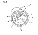
Figur 3 eine zweite perspektivische Ansicht der Federmutter ausFigur 1 .
-
FIG. 1 a perspective view of a spring nut according to the invention, -
FIG. 2 a sectional view through the spring nutFIG. 1 , and -
FIG. 3 a second perspective view of the spring nutFIG. 1 ,
In
Wie in den
Die Federmutter 10 weist des Weiteren eine innere Wandung 24 auf, die, wie im Folgenden dargestellt wird, durch mehrere federnde Laschen 26 gebildet ist. An einer Stirnwand 28, die einer Einschuböffnung 30 für den Bolzen 12 gegenüberliegt, ist ein Steg 32 vorgesehen, an dem die Federlaschen 26 mit einem stirnseitigen Ende 34 federnd gehalten sind. Ein freies Ende 36 der Federlaschen 26 weist in Richtung der Einschuböffnung 30 und ist in radialer Richtung federnd ausgebildet.The
Wie in
Die Federmutter 10 kann zur Befestigung des ersten Bauteils 14 in axialer Richtung A auf den Bolzen 12 aufgeschoben und durch die Rastelemente 38 an diesem verrastet werden. Da sowohl die Federlaschen 26 wie auch die Rastelemente 38 in radialer Richtung nachgiebig ausgebildet sind, ist die Federmutter 10 an verschiedene Größen bzw. Durchmesser des Bolzens 12 anpassbar. In Umfangsrichtung wird der Bolzen vollständig von der äußeren Wandung 22 und zumindest teilweise durch die Federlaschen 26 bedeckt. In axialer Richtung wird der Bolzen an der Stirnwand 28 vollständig vom Steg 32 bedeckt. Im in
Wie insbesondere in
Die Anzahl der Federlaschen 26 bzw. der Rastelemente 38 sowie die Anordnung des Stegs 32 kann beliebig an die jeweiligen Anforderungen angepasst werden. Es ist lediglich sicherzustellen, dass sich diese in axialer Richtung A nicht überlappen, um die einfache Herstellung der Federmutter 10 sicherzustellen.The number of
Wie insbesondere in
Wie in
Claims (8)
Priority Applications (5)
| Application Number | Priority Date | Filing Date | Title |
|---|---|---|---|
| ES11010276.1T ES2628121T3 (en) | 2011-12-29 | 2011-12-29 | Elastic nut |
| EP11010276.1A EP2610506B1 (en) | 2011-12-29 | 2011-12-29 | Spring nut |
| US13/721,682 US9039339B2 (en) | 2011-12-29 | 2012-12-20 | Spring nut |
| CN201210583529.1A CN103185059B (en) | 2011-12-29 | 2012-12-28 | Spring nut |
| KR1020120156579A KR20130077800A (en) | 2011-12-29 | 2012-12-28 | Spring nut |
Applications Claiming Priority (1)
| Application Number | Priority Date | Filing Date | Title |
|---|---|---|---|
| EP11010276.1A EP2610506B1 (en) | 2011-12-29 | 2011-12-29 | Spring nut |
Publications (2)
| Publication Number | Publication Date |
|---|---|
| EP2610506A1 true EP2610506A1 (en) | 2013-07-03 |
| EP2610506B1 EP2610506B1 (en) | 2017-03-15 |
Family
ID=45495590
Family Applications (1)
| Application Number | Title | Priority Date | Filing Date |
|---|---|---|---|
| EP11010276.1A Active EP2610506B1 (en) | 2011-12-29 | 2011-12-29 | Spring nut |
Country Status (5)
| Country | Link |
|---|---|
| US (1) | US9039339B2 (en) |
| EP (1) | EP2610506B1 (en) |
| KR (1) | KR20130077800A (en) |
| CN (1) | CN103185059B (en) |
| ES (1) | ES2628121T3 (en) |
Cited By (11)
| Publication number | Priority date | Publication date | Assignee | Title |
|---|---|---|---|---|
| EP2860410A1 (en) * | 2013-09-23 | 2015-04-15 | The Boeing Company | Systems and methods for use in covering a portion of a fastener protruding from a surface |
| US9618029B2 (en) | 2013-09-23 | 2017-04-11 | The Boeing Company | Systems and methods for use in covering a portion of a fastener protruding from a surface |
| DE102017110947A1 (en) | 2017-05-19 | 2018-11-22 | Illinois Tool Works Inc. | Device for fastening to a bolt of a carrier component |
| US10655667B2 (en) | 2017-09-28 | 2020-05-19 | The Boeing Company | Rapid installation thermoplastic EME protection cap |
| US10920818B2 (en) | 2018-04-27 | 2021-02-16 | The Boeing Company | Anchoring washer for an EME protection cap system |
| US10948004B2 (en) | 2018-07-26 | 2021-03-16 | The Boeing Company | Anchoring bolt head for an EME protection cap system |
| US10962043B2 (en) | 2018-04-24 | 2021-03-30 | The Boeing Company | Anchoring nut for an EME protection cap system |
| US10982704B2 (en) | 2019-01-03 | 2021-04-20 | The Boeing Company | EME protection cap system with screw sealant mechanism |
| US11236777B2 (en) | 2019-05-06 | 2022-02-01 | The Boeing Company | Friction fit electromagnetic effect protection cap system |
| US11754111B2 (en) | 2020-03-16 | 2023-09-12 | The Boeing Company | Compression fit EME protection seal cap |
| US11788573B2 (en) | 2019-05-23 | 2023-10-17 | The Boeing Company | Multi-component melt electromagnetic effect protection cap system |
Families Citing this family (7)
| Publication number | Priority date | Publication date | Assignee | Title |
|---|---|---|---|---|
| JP6240060B2 (en) * | 2014-12-18 | 2017-11-29 | トヨタ自動車株式会社 | Temporary fastener and retainer for held member |
| USD892609S1 (en) * | 2016-10-31 | 2020-08-11 | Nan Huang Huang | Gear lug nut cover |
| USD885879S1 (en) * | 2016-10-31 | 2020-06-02 | Grand General Accessories Manufacturing | Flat top cone lug nut cover |
| US10087974B2 (en) * | 2016-12-06 | 2018-10-02 | David Szymczak | Protection cap assembly for one or more bolts |
| JP6980718B2 (en) * | 2019-06-28 | 2021-12-15 | 大和化成工業株式会社 | Assembly structure |
| USD899915S1 (en) * | 2019-07-02 | 2020-10-27 | Yuan Li Hsing Industrial Co., Ltd. | Tool head |
| US11519449B2 (en) * | 2020-03-30 | 2022-12-06 | David Gilder | Bolt-covering cap |
Citations (4)
| Publication number | Priority date | Publication date | Assignee | Title |
|---|---|---|---|---|
| US2339664A (en) * | 1942-08-13 | 1944-01-18 | Tinnerman Products Inc | Fastening device |
| DE3728070A1 (en) * | 1986-09-02 | 1988-03-03 | Nifco Inc | PLASTIC NUT |
| DE19733771C1 (en) | 1997-08-05 | 1999-06-10 | Raymond A & Cie | Detachable spring nut for threaded bolts |
| EP1621782A1 (en) * | 2004-07-30 | 2006-02-01 | I.T.W. De France | Female attachment and obturator including it |
Family Cites Families (13)
| Publication number | Priority date | Publication date | Assignee | Title |
|---|---|---|---|---|
| US2040383A (en) * | 1934-06-20 | 1936-05-12 | Jasper Christiaan Hendrik | Means for joining electric current conductors |
| US3701373A (en) * | 1971-03-03 | 1972-10-31 | Illinois Tool Works | Grommet type fastener |
| US4571136A (en) * | 1984-02-10 | 1986-02-18 | Illinois Tool Works Inc. | Plastic push-on fastener |
| US4756654A (en) * | 1984-06-13 | 1988-07-12 | Trw Inc. | Fastening device |
| GB8618340D0 (en) * | 1986-07-28 | 1986-09-03 | Itw Ltd | Fastening assemblies |
| US4850778A (en) * | 1988-07-27 | 1989-07-25 | Trw, Inc. | Push-on fastener |
| DE9205186U1 (en) * | 1992-04-14 | 1992-06-17 | Emhart Inc., Newark, Del., Us | |
| US5642973A (en) * | 1995-12-26 | 1997-07-01 | Pretty; Daniel Glenn | Plumbing cleanout cover |
| CN1098979C (en) * | 1996-01-26 | 2003-01-15 | 尼科拉伊·蒂莫菲维奇·罗加特涅夫 | Seal-locking mechanism |
| MY135737A (en) * | 1996-02-09 | 2008-06-30 | Petronas Res & Scient Services Sdn Bhd | Protective caps for bolts with nuts |
| US5810532A (en) * | 1997-05-09 | 1998-09-22 | Grand General Accessories Manufacturing Inc. | Vehicle lug nut covers |
| CA2365208C (en) * | 1999-03-22 | 2008-05-13 | Alcoa Inc. | Two-piece cover for bolt and nut assembly and clip thereof |
| DE102005015033A1 (en) * | 2005-03-31 | 2006-10-05 | Newfrey Llc, Newark | Fastening element for attachment to a threaded bolt |
-
2011
- 2011-12-29 ES ES11010276.1T patent/ES2628121T3/en active Active
- 2011-12-29 EP EP11010276.1A patent/EP2610506B1/en active Active
-
2012
- 2012-12-20 US US13/721,682 patent/US9039339B2/en active Active
- 2012-12-28 KR KR1020120156579A patent/KR20130077800A/en not_active Application Discontinuation
- 2012-12-28 CN CN201210583529.1A patent/CN103185059B/en active Active
Patent Citations (4)
| Publication number | Priority date | Publication date | Assignee | Title |
|---|---|---|---|---|
| US2339664A (en) * | 1942-08-13 | 1944-01-18 | Tinnerman Products Inc | Fastening device |
| DE3728070A1 (en) * | 1986-09-02 | 1988-03-03 | Nifco Inc | PLASTIC NUT |
| DE19733771C1 (en) | 1997-08-05 | 1999-06-10 | Raymond A & Cie | Detachable spring nut for threaded bolts |
| EP1621782A1 (en) * | 2004-07-30 | 2006-02-01 | I.T.W. De France | Female attachment and obturator including it |
Cited By (19)
| Publication number | Priority date | Publication date | Assignee | Title |
|---|---|---|---|---|
| US11149780B2 (en) | 2013-09-23 | 2021-10-19 | The Boeing Company | Method of covering a portion of a fastener protruding from a surface |
| EP3078866A1 (en) * | 2013-09-23 | 2016-10-12 | The Boeing Company | Systems and methods for use in covering a portion of a fastener protruding from a surface |
| US9541118B2 (en) | 2013-09-23 | 2017-01-10 | The Boeing Company | Systems and methods for use in covering a portion of a fastener protruding from a surface |
| US9618029B2 (en) | 2013-09-23 | 2017-04-11 | The Boeing Company | Systems and methods for use in covering a portion of a fastener protruding from a surface |
| RU2676750C2 (en) * | 2013-09-23 | 2019-01-11 | Зе Боинг Компани | Systems and methods used in covering portion of fastener protruding from surface |
| US10233961B2 (en) | 2013-09-23 | 2019-03-19 | The Boeing Company | Methods for covering a portion of a fastener protruding from a surface |
| US10495132B2 (en) | 2013-09-23 | 2019-12-03 | The Boeing Company | Methods for use in covering a portion of a fastener protruding from a surface |
| EP2860410A1 (en) * | 2013-09-23 | 2015-04-15 | The Boeing Company | Systems and methods for use in covering a portion of a fastener protruding from a surface |
| DE102017110947A1 (en) | 2017-05-19 | 2018-11-22 | Illinois Tool Works Inc. | Device for fastening to a bolt of a carrier component |
| US10655667B2 (en) | 2017-09-28 | 2020-05-19 | The Boeing Company | Rapid installation thermoplastic EME protection cap |
| US10962043B2 (en) | 2018-04-24 | 2021-03-30 | The Boeing Company | Anchoring nut for an EME protection cap system |
| US11732743B2 (en) | 2018-04-24 | 2023-08-22 | The Boeing Company | Anchoring nut for an EME protection cap system |
| US10920818B2 (en) | 2018-04-27 | 2021-02-16 | The Boeing Company | Anchoring washer for an EME protection cap system |
| US11725687B2 (en) | 2018-04-27 | 2023-08-15 | The Boeing Company | Anchoring washer for an EME protection cap system |
| US10948004B2 (en) | 2018-07-26 | 2021-03-16 | The Boeing Company | Anchoring bolt head for an EME protection cap system |
| US10982704B2 (en) | 2019-01-03 | 2021-04-20 | The Boeing Company | EME protection cap system with screw sealant mechanism |
| US11236777B2 (en) | 2019-05-06 | 2022-02-01 | The Boeing Company | Friction fit electromagnetic effect protection cap system |
| US11788573B2 (en) | 2019-05-23 | 2023-10-17 | The Boeing Company | Multi-component melt electromagnetic effect protection cap system |
| US11754111B2 (en) | 2020-03-16 | 2023-09-12 | The Boeing Company | Compression fit EME protection seal cap |
Also Published As
| Publication number | Publication date |
|---|---|
| CN103185059B (en) | 2016-08-17 |
| CN103185059A (en) | 2013-07-03 |
| KR20130077800A (en) | 2013-07-09 |
| EP2610506B1 (en) | 2017-03-15 |
| US9039339B2 (en) | 2015-05-26 |
| ES2628121T3 (en) | 2017-08-01 |
| US20130170923A1 (en) | 2013-07-04 |
Similar Documents
| Publication | Publication Date | Title |
|---|---|---|
| EP2610506B1 (en) | Spring nut | |
| EP3064790B1 (en) | Plug-in coupling comprising coupling element and ball stud | |
| DE112008004188B4 (en) | Fixing structure with a grommet | |
| EP0381980B1 (en) | Device for the fixation and through-put cables, conduits, tubes or hoses | |
| EP3698056B1 (en) | Tolerance compensation assembly | |
| EP2513922B1 (en) | Device for removably fixing a conductor to a current transformer housing | |
| DE102014103535A1 (en) | Device for fastening a component to a carrier component | |
| EP2183517B1 (en) | Connecting and attachment component for a corrugated hose | |
| DE102019134107A1 (en) | FASTENING CLIP | |
| DE102007042654A1 (en) | Ball screw for use with brake for adjusting brake shoes, has ball channel that is finite, so that balls are movable back and forth between ends along ball channel, where ends of channel are formed by closure part attached at spindle nut | |
| DE102018113895A1 (en) | System for fixing a first component to a second component | |
| DE102018102291A1 (en) | Device for compensating tolerances | |
| DE2840648C3 (en) | Connection piece for lines for carrying gaseous or liquid media | |
| DE102004014593B4 (en) | Device for attachment to a provided with a threaded bolt carrier part | |
| DE102017116255A1 (en) | Threaded nut for a ball screw drive | |
| EP2978080B1 (en) | Connector assembly | |
| DE102017105733A1 (en) | Spindle nut for a ball screw and method for producing a spindle nut | |
| DE202009008754U1 (en) | rosette arrangement | |
| DE202008003139U1 (en) | Locking threaded sleeve | |
| DE102009038080A1 (en) | Connecting arrangement for high pressure fuel pump of internal combustion engine, has recess circulating in circumferential direction of connecting element, where contour of another connecting element is accommodated in sections by recess | |
| DE202013006220U1 (en) | Device for implementing a screw connection | |
| DE102010061553A1 (en) | Fastening element for vibration damper, has annular absorber mass, where annular elastomeric spring is coupled to dimensionally rigid perforated disk | |
| EP2612040A1 (en) | Expansion anchor | |
| DE202008016230U1 (en) | Device for connecting components | |
| DE102016101772A1 (en) | Fastener for fastening a component to a carrier component |
Legal Events
| Date | Code | Title | Description |
|---|---|---|---|
| PUAI | Public reference made under article 153(3) epc to a published international application that has entered the european phase |
Free format text: ORIGINAL CODE: 0009012 |
|
| AK | Designated contracting states |
Kind code of ref document: A1 Designated state(s): AL AT BE BG CH CY CZ DE DK EE ES FI FR GB GR HR HU IE IS IT LI LT LU LV MC MK MT NL NO PL PT RO RS SE SI SK SM TR |
|
| AX | Request for extension of the european patent |
Extension state: BA ME |
|
| 17P | Request for examination filed |
Effective date: 20130617 |
|
| RBV | Designated contracting states (corrected) |
Designated state(s): AL AT BE BG CH CY CZ DE DK EE ES FI FR GB GR HR HU IE IS IT LI LT LU LV MC MK MT NL NO PL PT RO RS SE SI SK SM TR |
|
| GRAP | Despatch of communication of intention to grant a patent |
Free format text: ORIGINAL CODE: EPIDOSNIGR1 |
|
| RIC1 | Information provided on ipc code assigned before grant |
Ipc: F16B 37/14 20060101ALN20160617BHEP Ipc: F16B 37/08 20060101AFI20160617BHEP |
|
| RIC1 | Information provided on ipc code assigned before grant |
Ipc: F16B 37/08 20060101AFI20160624BHEP Ipc: F16B 37/14 20060101ALN20160624BHEP |
|
| INTG | Intention to grant announced |
Effective date: 20160712 |
|
| GRAS | Grant fee paid |
Free format text: ORIGINAL CODE: EPIDOSNIGR3 |
|
| GRAA | (expected) grant |
Free format text: ORIGINAL CODE: 0009210 |
|
| RAP1 | Party data changed (applicant data changed or rights of an application transferred) |
Owner name: ITW FASTENER PRODUCTS GMBH |
|
| AK | Designated contracting states |
Kind code of ref document: B1 Designated state(s): AL AT BE BG CH CY CZ DE DK EE ES FI FR GB GR HR HU IE IS IT LI LT LU LV MC MK MT NL NO PL PT RO RS SE SI SK SM TR |
|
| REG | Reference to a national code |
Ref country code: CH Ref legal event code: EP Ref country code: GB Ref legal event code: FG4D Free format text: NOT ENGLISH |
|
| REG | Reference to a national code |
Ref country code: IE Ref legal event code: FG4D Free format text: LANGUAGE OF EP DOCUMENT: GERMAN |
|
| REG | Reference to a national code |
Ref country code: AT Ref legal event code: REF Ref document number: 875897 Country of ref document: AT Kind code of ref document: T Effective date: 20170415 |
|
| REG | Reference to a national code |
Ref country code: DE Ref legal event code: R096 Ref document number: 502011011824 Country of ref document: DE |
|
| REG | Reference to a national code |
Ref country code: NL Ref legal event code: MP Effective date: 20170315 |
|
| REG | Reference to a national code |
Ref country code: LT Ref legal event code: MG4D |
|
| PG25 | Lapsed in a contracting state [announced via postgrant information from national office to epo] |
Ref country code: GR Free format text: LAPSE BECAUSE OF FAILURE TO SUBMIT A TRANSLATION OF THE DESCRIPTION OR TO PAY THE FEE WITHIN THE PRESCRIBED TIME-LIMIT Effective date: 20170616 Ref country code: NO Free format text: LAPSE BECAUSE OF FAILURE TO SUBMIT A TRANSLATION OF THE DESCRIPTION OR TO PAY THE FEE WITHIN THE PRESCRIBED TIME-LIMIT Effective date: 20170615 Ref country code: HR Free format text: LAPSE BECAUSE OF FAILURE TO SUBMIT A TRANSLATION OF THE DESCRIPTION OR TO PAY THE FEE WITHIN THE PRESCRIBED TIME-LIMIT Effective date: 20170315 Ref country code: FI Free format text: LAPSE BECAUSE OF FAILURE TO SUBMIT A TRANSLATION OF THE DESCRIPTION OR TO PAY THE FEE WITHIN THE PRESCRIBED TIME-LIMIT Effective date: 20170315 Ref country code: LT Free format text: LAPSE BECAUSE OF FAILURE TO SUBMIT A TRANSLATION OF THE DESCRIPTION OR TO PAY THE FEE WITHIN THE PRESCRIBED TIME-LIMIT Effective date: 20170315 |
|
| REG | Reference to a national code |
Ref country code: ES Ref legal event code: FG2A Ref document number: 2628121 Country of ref document: ES Kind code of ref document: T3 Effective date: 20170801 |
|
| PG25 | Lapsed in a contracting state [announced via postgrant information from national office to epo] |
Ref country code: SE Free format text: LAPSE BECAUSE OF FAILURE TO SUBMIT A TRANSLATION OF THE DESCRIPTION OR TO PAY THE FEE WITHIN THE PRESCRIBED TIME-LIMIT Effective date: 20170315 Ref country code: RS Free format text: LAPSE BECAUSE OF FAILURE TO SUBMIT A TRANSLATION OF THE DESCRIPTION OR TO PAY THE FEE WITHIN THE PRESCRIBED TIME-LIMIT Effective date: 20170315 Ref country code: LV Free format text: LAPSE BECAUSE OF FAILURE TO SUBMIT A TRANSLATION OF THE DESCRIPTION OR TO PAY THE FEE WITHIN THE PRESCRIBED TIME-LIMIT Effective date: 20170315 Ref country code: BG Free format text: LAPSE BECAUSE OF FAILURE TO SUBMIT A TRANSLATION OF THE DESCRIPTION OR TO PAY THE FEE WITHIN THE PRESCRIBED TIME-LIMIT Effective date: 20170615 |
|
| PG25 | Lapsed in a contracting state [announced via postgrant information from national office to epo] |
Ref country code: NL Free format text: LAPSE BECAUSE OF FAILURE TO SUBMIT A TRANSLATION OF THE DESCRIPTION OR TO PAY THE FEE WITHIN THE PRESCRIBED TIME-LIMIT Effective date: 20170315 |
|
| PG25 | Lapsed in a contracting state [announced via postgrant information from national office to epo] |
Ref country code: RO Free format text: LAPSE BECAUSE OF FAILURE TO SUBMIT A TRANSLATION OF THE DESCRIPTION OR TO PAY THE FEE WITHIN THE PRESCRIBED TIME-LIMIT Effective date: 20170315 Ref country code: CZ Free format text: LAPSE BECAUSE OF FAILURE TO SUBMIT A TRANSLATION OF THE DESCRIPTION OR TO PAY THE FEE WITHIN THE PRESCRIBED TIME-LIMIT Effective date: 20170315 Ref country code: EE Free format text: LAPSE BECAUSE OF FAILURE TO SUBMIT A TRANSLATION OF THE DESCRIPTION OR TO PAY THE FEE WITHIN THE PRESCRIBED TIME-LIMIT Effective date: 20170315 Ref country code: SK Free format text: LAPSE BECAUSE OF FAILURE TO SUBMIT A TRANSLATION OF THE DESCRIPTION OR TO PAY THE FEE WITHIN THE PRESCRIBED TIME-LIMIT Effective date: 20170315 |
|
| PG25 | Lapsed in a contracting state [announced via postgrant information from national office to epo] |
Ref country code: PT Free format text: LAPSE BECAUSE OF FAILURE TO SUBMIT A TRANSLATION OF THE DESCRIPTION OR TO PAY THE FEE WITHIN THE PRESCRIBED TIME-LIMIT Effective date: 20170717 Ref country code: PL Free format text: LAPSE BECAUSE OF FAILURE TO SUBMIT A TRANSLATION OF THE DESCRIPTION OR TO PAY THE FEE WITHIN THE PRESCRIBED TIME-LIMIT Effective date: 20170315 Ref country code: IS Free format text: LAPSE BECAUSE OF FAILURE TO SUBMIT A TRANSLATION OF THE DESCRIPTION OR TO PAY THE FEE WITHIN THE PRESCRIBED TIME-LIMIT Effective date: 20170715 Ref country code: SM Free format text: LAPSE BECAUSE OF FAILURE TO SUBMIT A TRANSLATION OF THE DESCRIPTION OR TO PAY THE FEE WITHIN THE PRESCRIBED TIME-LIMIT Effective date: 20170315 |
|
| REG | Reference to a national code |
Ref country code: DE Ref legal event code: R097 Ref document number: 502011011824 Country of ref document: DE |
|
| REG | Reference to a national code |
Ref country code: FR Ref legal event code: PLFP Year of fee payment: 7 |
|
| PLBE | No opposition filed within time limit |
Free format text: ORIGINAL CODE: 0009261 |
|
| STAA | Information on the status of an ep patent application or granted ep patent |
Free format text: STATUS: NO OPPOSITION FILED WITHIN TIME LIMIT |
|
| PG25 | Lapsed in a contracting state [announced via postgrant information from national office to epo] |
Ref country code: DK Free format text: LAPSE BECAUSE OF FAILURE TO SUBMIT A TRANSLATION OF THE DESCRIPTION OR TO PAY THE FEE WITHIN THE PRESCRIBED TIME-LIMIT Effective date: 20170315 |
|
| 26N | No opposition filed |
Effective date: 20171218 |
|
| PG25 | Lapsed in a contracting state [announced via postgrant information from national office to epo] |
Ref country code: SI Free format text: LAPSE BECAUSE OF FAILURE TO SUBMIT A TRANSLATION OF THE DESCRIPTION OR TO PAY THE FEE WITHIN THE PRESCRIBED TIME-LIMIT Effective date: 20170315 |
|
| PGFP | Annual fee paid to national office [announced via postgrant information from national office to epo] |
Ref country code: ES Payment date: 20180102 Year of fee payment: 7 |
|
| REG | Reference to a national code |
Ref country code: CH Ref legal event code: PL |
|
| GBPC | Gb: european patent ceased through non-payment of renewal fee |
Effective date: 20171229 |
|
| REG | Reference to a national code |
Ref country code: IE Ref legal event code: MM4A |
|
| PG25 | Lapsed in a contracting state [announced via postgrant information from national office to epo] |
Ref country code: LU Free format text: LAPSE BECAUSE OF NON-PAYMENT OF DUE FEES Effective date: 20171229 Ref country code: MT Free format text: LAPSE BECAUSE OF FAILURE TO SUBMIT A TRANSLATION OF THE DESCRIPTION OR TO PAY THE FEE WITHIN THE PRESCRIBED TIME-LIMIT Effective date: 20170315 |
|
| REG | Reference to a national code |
Ref country code: BE Ref legal event code: MM Effective date: 20171231 |
|
| PG25 | Lapsed in a contracting state [announced via postgrant information from national office to epo] |
Ref country code: IE Free format text: LAPSE BECAUSE OF NON-PAYMENT OF DUE FEES Effective date: 20171229 |
|
| PG25 | Lapsed in a contracting state [announced via postgrant information from national office to epo] |
Ref country code: BE Free format text: LAPSE BECAUSE OF NON-PAYMENT OF DUE FEES Effective date: 20171231 Ref country code: CH Free format text: LAPSE BECAUSE OF NON-PAYMENT OF DUE FEES Effective date: 20171231 Ref country code: LI Free format text: LAPSE BECAUSE OF NON-PAYMENT OF DUE FEES Effective date: 20171231 Ref country code: GB Free format text: LAPSE BECAUSE OF NON-PAYMENT OF DUE FEES Effective date: 20171229 |
|
| REG | Reference to a national code |
Ref country code: AT Ref legal event code: MM01 Ref document number: 875897 Country of ref document: AT Kind code of ref document: T Effective date: 20171229 |
|
| PG25 | Lapsed in a contracting state [announced via postgrant information from national office to epo] |
Ref country code: AT Free format text: LAPSE BECAUSE OF NON-PAYMENT OF DUE FEES Effective date: 20171229 |
|
| PG25 | Lapsed in a contracting state [announced via postgrant information from national office to epo] |
Ref country code: MC Free format text: LAPSE BECAUSE OF FAILURE TO SUBMIT A TRANSLATION OF THE DESCRIPTION OR TO PAY THE FEE WITHIN THE PRESCRIBED TIME-LIMIT Effective date: 20170315 Ref country code: HU Free format text: LAPSE BECAUSE OF FAILURE TO SUBMIT A TRANSLATION OF THE DESCRIPTION OR TO PAY THE FEE WITHIN THE PRESCRIBED TIME-LIMIT; INVALID AB INITIO Effective date: 20111229 |
|
| PG25 | Lapsed in a contracting state [announced via postgrant information from national office to epo] |
Ref country code: CY Free format text: LAPSE BECAUSE OF NON-PAYMENT OF DUE FEES Effective date: 20170315 |
|
| PG25 | Lapsed in a contracting state [announced via postgrant information from national office to epo] |
Ref country code: MK Free format text: LAPSE BECAUSE OF FAILURE TO SUBMIT A TRANSLATION OF THE DESCRIPTION OR TO PAY THE FEE WITHIN THE PRESCRIBED TIME-LIMIT Effective date: 20170315 |
|
| REG | Reference to a national code |
Ref country code: ES Ref legal event code: FD2A Effective date: 20200204 |
|
| PG25 | Lapsed in a contracting state [announced via postgrant information from national office to epo] |
Ref country code: TR Free format text: LAPSE BECAUSE OF FAILURE TO SUBMIT A TRANSLATION OF THE DESCRIPTION OR TO PAY THE FEE WITHIN THE PRESCRIBED TIME-LIMIT Effective date: 20170315 |
|
| PG25 | Lapsed in a contracting state [announced via postgrant information from national office to epo] |
Ref country code: ES Free format text: LAPSE BECAUSE OF NON-PAYMENT OF DUE FEES Effective date: 20181230 |
|
| PG25 | Lapsed in a contracting state [announced via postgrant information from national office to epo] |
Ref country code: AL Free format text: LAPSE BECAUSE OF FAILURE TO SUBMIT A TRANSLATION OF THE DESCRIPTION OR TO PAY THE FEE WITHIN THE PRESCRIBED TIME-LIMIT Effective date: 20170315 |
|
| PG25 | Lapsed in a contracting state [announced via postgrant information from national office to epo] |
Ref country code: IT Free format text: LAPSE BECAUSE OF NON-PAYMENT OF DUE FEES Effective date: 20191229 |
|
| PGFP | Annual fee paid to national office [announced via postgrant information from national office to epo] |
Ref country code: DE Payment date: 20221228 Year of fee payment: 12 |
|
| P01 | Opt-out of the competence of the unified patent court (upc) registered |
Effective date: 20231101 |
|
| PGFP | Annual fee paid to national office [announced via postgrant information from national office to epo] |
Ref country code: FR Payment date: 20231227 Year of fee payment: 13 |