EP2610203A1 - Monitor control device - Google Patents
Monitor control device Download PDFInfo
- Publication number
- EP2610203A1 EP2610203A1 EP10856420.4A EP10856420A EP2610203A1 EP 2610203 A1 EP2610203 A1 EP 2610203A1 EP 10856420 A EP10856420 A EP 10856420A EP 2610203 A1 EP2610203 A1 EP 2610203A1
- Authority
- EP
- European Patent Office
- Prior art keywords
- monitor
- camera
- indication
- image
- elevator
- Prior art date
- Legal status (The legal status is an assumption and is not a legal conclusion. Google has not performed a legal analysis and makes no representation as to the accuracy of the status listed.)
- Granted
Links
- 230000002265 prevention Effects 0.000 claims abstract description 64
- 238000001514 detection method Methods 0.000 claims description 49
- 238000012423 maintenance Methods 0.000 claims description 2
- 238000012544 monitoring process Methods 0.000 description 23
- 230000000694 effects Effects 0.000 description 13
- 238000004891 communication Methods 0.000 description 9
- 238000010586 diagram Methods 0.000 description 6
- 238000012545 processing Methods 0.000 description 4
- 238000000034 method Methods 0.000 description 2
- 238000012790 confirmation Methods 0.000 description 1
- 238000009434 installation Methods 0.000 description 1
- 239000004973 liquid crystal related substance Substances 0.000 description 1
- 239000000779 smoke Substances 0.000 description 1
- 238000005303 weighing Methods 0.000 description 1
Images


Classifications
-
- B—PERFORMING OPERATIONS; TRANSPORTING
- B66—HOISTING; LIFTING; HAULING
- B66B—ELEVATORS; ESCALATORS OR MOVING WALKWAYS
- B66B5/00—Applications of checking, fault-correcting, or safety devices in elevators
- B66B5/02—Applications of checking, fault-correcting, or safety devices in elevators responsive to abnormal operating conditions
- B66B5/021—Applications of checking, fault-correcting, or safety devices in elevators responsive to abnormal operating conditions the abnormal operating conditions being independent of the system
- B66B5/024—Applications of checking, fault-correcting, or safety devices in elevators responsive to abnormal operating conditions the abnormal operating conditions being independent of the system where the abnormal operating condition is caused by an accident, e.g. fire
-
- B—PERFORMING OPERATIONS; TRANSPORTING
- B66—HOISTING; LIFTING; HAULING
- B66B—ELEVATORS; ESCALATORS OR MOVING WALKWAYS
- B66B3/00—Applications of devices for indicating or signalling operating conditions of elevators
-
- B—PERFORMING OPERATIONS; TRANSPORTING
- B66—HOISTING; LIFTING; HAULING
- B66B—ELEVATORS; ESCALATORS OR MOVING WALKWAYS
- B66B5/00—Applications of checking, fault-correcting, or safety devices in elevators
- B66B5/02—Applications of checking, fault-correcting, or safety devices in elevators responsive to abnormal operating conditions
-
- B—PERFORMING OPERATIONS; TRANSPORTING
- B66—HOISTING; LIFTING; HAULING
- B66B—ELEVATORS; ESCALATORS OR MOVING WALKWAYS
- B66B1/00—Control systems of elevators in general
- B66B1/34—Details, e.g. call counting devices, data transmission from car to control system, devices giving information to the control system
- B66B1/46—Adaptations of switches or switchgear
- B66B1/468—Call registering systems
Definitions
- the present invention relates to a monitor controller which can appropriately control indications of a monitor installed in a disaster prevention center or the like.
- Patent Literature 1 proposes an elevator for evacuation purposes utilized in rescue activities by firefighters when a fire breaks out in a building.
- the configuration is such that a camera is installed on each floor of a building and a monitor is installed in a car of an elevator so that it is possible to cause an image photographed by the camera to show up on the monitor in the car.
- an operator for example, a firefighter
- Patent Literature 1 Japanese Patent Laid-Open No. 64-75378
- an elevator utilized for evacuation purposes during a fire is often installed in a relatively high building.
- the number of floors at which an elevator stops is large and, therefore, the number of cameras installed in halls becomes large inevitably.
- an operator in the car must make sure of the situation in each hall by sequentially switching images caused to show up on the monitor and this confirmation work requires much time.
- only with the images caused to show up on the monitor it may sometimes be difficult to identify the place where the fire has broken out and the like and it may be difficult to accurately grasp the present situation.
- the present invention was made in order to solve the problems described above and an object of the invention is to provide a monitor controller which can cause a monitor installed in a prescribed remote place to indicate various kinds of information. necessary for rescuing those who are present in a building in the case where an elevator is utilized for evacuation purposes during a fire.
- a monitor controller of the present invention is a monitor controller which comprises a monitor provided in a prescribed remote place away from a car and a hall of an elevator, indication control means which controls indications of the monitor, a first camera installed in the hall of the elevator, and operation control means which controls a normal operation of the elevator and an evacuation operation of the elevator during a fire.
- the indication control means causes the monitor to automatically indicate prescribed evacuation information including an image of the hall photographed by the first camera and information on a floor where the outbreak of a fire has been detected from fire detection information when the control of an evacuation operation is started by the operation control means.
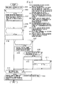
- FIG. 1 is a diagram showing the general configuration of a monitor controller in a first embodiment according to the present invention.
- reference numeral 1 denotes a car which ascends and descends in an elevator shaft
- reference numeral 2 denotes a control panel which performs the operation control of the whole elevator, such as the run control of the car 1.
- the control panel 2 performs, by the normal function thereof, normal services which involve causing the car 1 to respond successively to registered hall calls and car calls.
- this elevator has the function to be utilized for evacuation purposes in an emergency such as a fire, and the control panel 2 also performs control for this purpose as required.
- Reference numeral 3 denotes a disaster prevention center 3 provided on the first floor or the like of a building in which the elevator is provided.
- the disaster prevention center 3 consists of a facility installed in a prescribed remote place away from the car 1 and an elevator hall, and performs the central control of disaster prevention equipment, fire extinguishing equipment and the like in the building or in a prescribed area (the premises, etc.).
- Each elevator in the building or each elevator in the prescribed area is collectively controlled in this disaster prevention center 3, and the control panel 2 is connected to, for example, a central warning panel (not shown) of the disaster prevention center 3.
- a fire detector 4 is provided on each floor and a camera 5, an intercommunication device 6, and a rescue request button 7 (rescue request means) are provided in halls where the car 1 stops.
- the fire detector 4 has the function of detecting the outbreak of a fire from heat, smoke or the like.
- the fire detector 4 Upon detection of a fire, the fire detector 4 outputs information on the floor on which the fire has broken out, the place where the fire has broken out and the like as fire detection information to the disaster prevention center 3.
- the disaster prevention center 3 upon receipt of the fire detection information from the fire detector 4, the disaster prevention center 3 outputs the received fire detection information (or information corresponding to the fire detection information) to the control panel 2.
- the camera 5 is intended for photographing the situation in the hall. An image of each hall photographed by the camera 5 is inputted to the disaster prevention center 3.
- the intercommunication device 6 is a device by use of which a person in the hall has a conversation with a monitoring staff member of the disaster prevention center 3 and an operator in the can 1 (for example, a firefighter). Also the intercommunication device 6 is connected to the disaster prevention center 3 as is the camera 5.
- the rescue request button 7 is operated by those who are present in the building in making a request for a rescue by an elevator in an emergency such as a fire.
- the rescue request button 7 is connected directly to the control panel 2 and outputs rescue request information to the control panel 2 by being operated (pressed).
- rescue request information includes, for example, information to the effect that a rescue has been requested, and information on the floor where the rescue request button 7 is installed.
- the rescue request button 7 may also have the function of an authentication device.
- the rescue request button 7 is configured in such a manner that the operation of the rescue request button 7 becomes possible only in the case where personal authentication has been made by an authentication device.
- the rescue request button 7 may be configured in such a manner that a button operation is made unnecessary and when personal authentication has been made by an authentication device, rescue request information is automatically outputted to the control panel 2.
- the camera 5, intercommunication device 6, and rescue request button 7 are installed, for example, in a plurality of halls at which the car 1 stops. These pieces of equipment may be installed in all halls at which the car 1 stops or may be installed only in a part of the halls.
- a camera 8 and an intercommunication device 9 are provided in the car 1 of an elevator.
- the camera 8 is intended for photographing the situation in the car 1.
- An image of the inside of the car 1 photographed by the camera 8 is inputted to the disaster prevention center 3 via the control panel 2.
- the intercommunication device 9 is a device by use of which persons in the car 1 (a passenger, an operator and other persons) can communicate with the outside. Using this intercommunication device 9, a person in the car I has conversations with a monitoring staff member of the disaster prevention center 3 and a person who is using the intercommunication device 6 in the hall.
- the intercommunication device 9 is also connected to the disaster prevention center 3 via the control panel 2.
- the control panel 2 has the function of controlling a normal operation for performing the normal services and an evacuation operation for performing an evacuation by an elevator when a fire has broken out in the building.
- the control panel 2 is connected to the disaster prevention center 3, each rescue request button 7, and (each piece of equipment of) the car 1, and the essential part thereof consists of, for example, communication means 10, operation control means 11, boarding detection means 12, rescue-requested floor detection means 13, and stop detection means 14.
- the communication means 10 is provided in order that the control panel 2 performs the sending and receiving of information with each piece of connected equipment.
- the operation control means 11 has the function of controlling various kinds of operations of an elevator, such as a normal operation and an evacuation operation during a fire.
- the operation control means 11 performs a normal operation in normal times and performs control which involves causing the car 1 to respond successively to registered hall calls and car calls.
- the operation control means 11 starts prescribed control necessary for performing a rescue of those who are present in the building by switching the elevator from a normal operation to an evacuation operation in the case where prescribed start conditions are satisfied.
- the boarding detection means 12 has the function of detecting persons in the car 1. On the basis of an output of, for example, a load weighing device and a sensor (an infrared sensor or the like) provided in the car 1 and the like, or an image photographed by the camera 8, the boarding detection means 12 makes a determination as to whether or not a person is present in the car 1, and detects that a person is present in the car I in the case where prescribed conditions are satisfied. When the boarding detection means 12 has detected the presence of a person in the car 1, the boarding detection means 12 outputs the result also to the disaster prevention center 3 via the communication means 10.
- the rescue-requested floor detection means 13 has the function of detecting the floor on which a rescue request has been performed (the rescue-requested floor) on the basis of the rescue request information received from the rescue request button 7.
- the rescue-requested floor detection means 13 identifies the rescue-requested floor on the basis of the received rescue request information, the rescue-requested floor detection means 13 outputs the result also to the disaster prevention center 3 via the communication means 10.
- the stop detection means 14 has the function of detecting a prescribed landing determination for stopping the car 1 during a run.
- a prescribed landing determination such as a deceleration instruction to an elevator traction machine, becomes necessary for stopping the car 1 during a run.
- the stop detection means 14 detects that such a landing determination has been made, and identifies the floor at which the car 1 stops.
- the stop detection means 14 outputs the result also to the disaster prevention center 3 via the communication means 10.
- the disaster prevention center 3 is provided with a monitor 15, an intercommunication device 16, a controller 17, and manual changeover means 18.
- the monitor 15 is indented for providing monitoring information of an elevator, disaster prevention information of the building and the like to a monitoring staff member or other persons of the disaster prevention center 3, and consists of, for example, a liquid crystal display.
- general monitoring information is indicated on the monitor 15.
- evacuation information various kinds of information necessary for speedily and accurately performing an evacuation operation
- various kinds of information necessary for supporting rescue activities utilizing an elevator is indicated as evacuation information on the monitor 15 of the disaster prevention center 3.
- both general monitoring information and evacuation information are indicated on the monitor 15 by being switched therebetween, whereby the monitor 15 is effectively utilized and the number of monitors 15 can be reduced. Incidentally, concrete indication contents of the monitor 15 during an evacuation operation will be described later.
- the intercommunication device 16 is a device by use of which a monitoring staff member or other persons of the disaster prevention center 3 can communicate with the outside. That is, when an evacuation operation is being performed on the control panel 2, the monitoring staff member of the disaster prevention center 3 has conversations with persons in the car 1 (a passenger, an operator and other persons) and a person who is using an intercommunication device 6 in the hall.
- the controller 17 is provided in the central warning panel or the like of the disaster prevention center 3.
- the disaster prevention center 3 has the function of causing the monitor 15 to indicate images photographed by the cameras 5 and 8 in real time, and is configured in such a manner that the selection of the camera 5 and/or the camera 8 which causes the monitor 15 to indicate an image can be performed automatically or manually as required.
- the controller 17 is provided with communication means 19, fire information detection means 20, indication control means 21, indication selection means 22, and intercommunication selection means 23.
- the communication means 19 is provided in order that the disaster prevention center 3 performs the sending and receiving of information with each piece of connected equipment.
- the fire information detection means 20 has the function of detecting the floor where a fire has broken out and a place where a fire has broken out on the basis of the fire detection information received from the fire detector 4.
- the indication control means 21 has the function of controlling indications of the monitor 15 installed in the disaster prevention center 3. In normal times when a normal operation is performed in an elevator, the indication control means 21 causes the monitor 15 to indicate general monitoring information, such as the state of each piece of equipment installed in the building and the state of an elevator. On the other hand, when the control of an evacuation operation is started on the control panel 2 (by the operation control means 11), the indication control means 21 causes the monitor 15 to automatically indicate the evacuation information on the basis of information from the control panel 2, information from other means in the controller 17 and the like.
- the indication selection means 22 has the function of selecting the camera for causing the monitor 15 to indicate an image (hereinafter referred to also as the "image indication camera") from the cameras 5 installed in a plurality of halls and the camera 8 installed in the car 1. That is, the indication control means 21 causes the monitor 15 to indicate in real time images photographed by the camera 5 and/or the camera 8 selected by the indication selection means 22.
- image indication cameras selected by the indication selection means 22 may be one camera or may be a plurality of cameras (for example, 2 cameras, 4 cameras or the like).
- the indication selection means 22 selects the camera 5 installed on the floor where the fire has broken out as the image indication camera on the basis of the detection result of the fire information detection means 20. As a result of this, an image of the hall on the floor where the fire has broken out is caused to show up automatically on the monitor 15 of the disaster prevention center 3.
- the indication control means 21 causes the monitor 15 to indicate the information on the identified floor where the fire has broken out and the like as evacuation information.
- the indication selection means 22 selects the camera 5 installed on the rescue-requested floor as the image indication camera on the basis of the detection result of the rescue-requested floor detection means 13 of the control panel 2. As a result of this, an image of the hall of the rescue-requested floor is caused to show up automatically on the monitor 15.
- the indication control means 21 causes the monitor 15 to indicate the information on the identified rescue-requested floor as evacuation information.
- the indication selection means 22 selects the camera 5 installed on the floor at which the car 1 is to stop as the image indication camera. As a result of this, an image of the hall of the rescue floor at which the car 1 stops immediately thereafter is caused to show up automatically.
- the indication selection means 22 selects the camera 8 installed in the car 1 as the image indication camera. As a result of this, an image of the inside of the car 1 is caused to show up automatically.
- the intercommunication selection means 23 has the function of detecting the channel of the intercommunication device 16 of the disaster prevention center 3.
- the indication selection means 22 selects the camera in the place where the channel-selected intercommunication device is installed as the image indication camera. For example, when the intercommunication device 16 has selected the channel of one of the intercommunication devices 6, the indication selection means 22 selects the camera 5 of the floor where the intercommunication device 6 is installed as the image indication camera. As a result of this, an image of the hall of the floor on which the channel-selected intercommunication device 6 is installed is caused to show up automatically on the monitor 15.
- the indication selection means 22 selects the camera 8 as the image indication camera. As a result of this, an image of the inside of the car 1 is caused to show up automatically on the monitor 15.
- the manual changeover means 18 is provided in order to cause a monitoring staff member or other persons of the disaster prevention center 3 to manually perform the selection of the camera which causes the monitor 15 to indicate images. That is, the monitoring staff member of the disaster prevention center 3 selects one or more of camera 5 and/or camera 8 by the manual changeover means 18, thereby enabling an image of the hall and/or an image of the inside of a car photographed by a desired camera to show up on the monitor 15.
- Figure 2 is a flowchart showing the operations of the monitor controller in the first embodiment according to the present invention
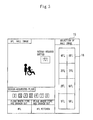
- Figure 3 is a diagram showing an example of an indication of the monitor in the disaster prevention center.
- the fire detection information from the fire detector 4 is inputted to the disaster prevention center 3.
- the controller 17 of the disaster prevention center 3 upon receipt of the fire detection information by the communication means 19, the outbreak of the fire is made sure of (S101) and the processing shown below is performed.
- the fire detection information from the fire detector 4 is inputted also to the elevator control panel 2 via the disaster prevention center 3.
- the start conditions for utilizing an elevator during a fire are stored beforehand in the control panel 2, and by comparing the present state of the elevator with the start conditions, the operation control means 11 makes a determination as to whether or not a changeover to an evacuation operation is possible. For example, in the case where the start conditions do not hold as in the case where a prescribed safety device is in operation, an evacuation operation is not started in the elevator. In this case, a determination is made in the controller 17 that the elevator cannot be utilized (No in S102), and the indication control means 21, for example, causes the indication of general monitoring information to be continued.
- the operation control means 11 causes the elevator to make a changeover from a normal operation to an evacuation operation.
- the disaster prevention center 3 by detecting this changeover to an evacuation operation, in S102 a determination is made that the elevator can be utilized.
- the monitor control for supporting rescue activities utilizing the elevator is started in the controller 17.
- the indication control means 21 because of the detection of the switching to an evacuation operation the indication contents of the monitor 15 are changed from the existing general monitoring information to evacuation information during a fire (S103).
- the indication control means 21 causes the monitor 15 to indicate, as evacuation information during a fire, an image of the hall by the camera 5 and an image of the inside of the car by the camera 8, as well as the information on the floor where the fire has broken out, the place where the fire has broken out, and the rescue-requested floor (S104).
- images caused to show up on the monitor 15 are those photographed by the camera 5 and/or camera 8 selected by the indication selection means 22 as the image indication camera.
- An evacuation operation during a fire is started when the fire detector 4 detects the outbreak of a fire. For this reason, immediately after the start of an evacuation operation (i.e., in S104), the camera 5 of the floor where the fire has broken out is selected by the indication selection means 22 as the image indication camera and at least an image of the hall of the floor where the fire has broken out is caused to show up on the monitor 15.
- the indication selection means 22 makes a determination as to whether or not the intercommunication device 16 of the disaster prevention center 3 has selected the channel of any of the intercommunication devices 6 installed in a hall (S105).
- the indication selection means 22 selects the camera 5 of the floor where the intercommunication device 6 whose channel has been selected by the intercommunication device 16 is installed as the image indication camera, and causes the monitor 15 to preferentially indicate an image of the hall (S106).
- the indication selection means 22 selects the camera 8 in the car 1 as the image indication camera, and causes the monitor 15 to preferentially indicate an image of the inside of the car (S108).
- the indication selection means 22 makes a determination as to whether or not a rescue request button 7 of a hall has been operated (S109). If any of the rescue request buttons 7 has been operated, the indication selection means 22 selects the camera 5 of the floor where the operated rescue request button 7 is installed as the image indication camera, and causes the monitor 15 to preferentially indicate an image of the hall (S110).
- Figure 3 shows an example of an indication of the monitor 15 in S110.
- whether or not a rescue request has been performed is indicated for each floor on the monitor 15.
- the camera 5 of the 5th floor for which a rescue request button 7 was operated is selected as the image indication camera, and an image of the hall of the 5th floor is indicated on the monitor 15.
- a rescue request button 7 of the 3rd floor is also operated.
- the indication selection means 22 may select both cameras 5 of the 3rd floor and the 5th floor as the image indication camera and an image of the hall of the 3rd floor and an image of the hall of the 5th floor may be indicated by split-screen display or may be indicated alternately in a prescribe region of the monitor 15.
- the indication selection means 22 may select the camera 5 of the floor where a rescue request button 7 operated later is installed as the image indication camera.
- Figure 3 shows an example in which the manual changeover means 18 is caused to show up on the monitor 15.
- the manual changeover means 18 may be composed of a touch panel type button so that the manual selection of cameras can be performed in the monitor 15.
- the indication selection means 22 makes a determination as to whether or not a landing determination of an elevator has been made (S111).
- the indication selection means 22 selects the camera 5 on the floor where the car 1 stops next as the image indication camera, and causes the monitor 15 to preferentially indicate an image of the hall (S112).
- the monitor 15 is caused to indicate a new image of the hall or a new image of the inside of a car or after in S111 a determination is made to the effect that a landing determination has not been made, the indication selection means 22 makes a determination as to whether or not the manual selection of a camera has been performed by the manual changeover means 18 (S113).
- the manual changeover means 18 S114
- the automatic selection processing of the image indication camera shown in the above-described S104 to S112 is preferentially performed and an appropriate image suited to the present situation is indicated on the monitor 15.
- the indication selection means 22 selects the camera 5 (of the floor) identified by the manual changeover means 18 as the image indication camera, and causes the monitor 15 to preferentially indicate an image of the hall (S115).
- a switching of the indication of the monitor 15 may be performed by preferentially performing the automatic selection processing of the image indication camera.
- the monitor 15 of the disaster prevention center 3 in the case where an elevator is utilized for evacuation purposes during a fire, it is possible to cause the monitor 15 of the disaster prevention center 3 to indicate various kinds of information necessary for rescuing those who are present in a building by an elevator (that is, in order to support rescue activities utilizing an elevator). That is, a monitoring staff member of the disaster prevention center 3 can instantaneously grasp, from the indication contents of the monitor 15, information on the place where the fire has broken out in the building and information on the floor where those who are present in the building and require an evacuation by the elevator (for example, wheelchair users) are present. As a result of this, the monitoring staff member of the disaster prevention center 3 can give appropriate instructions to an operator and other persons in the car 1, making it possible to realize speedy and accurate rescue activities utilizing the elevator.
- the monitor 15 is caused to indicate an image of the hall by the camera 5 and an image of the inside of the car 1 by the camera 8, as well as each information on the floor where a fire has broken out, the place where a fire has broken out and a rescue-requested floor as evacuation information during a fire.
- information on a specific place where a fire has broken out is not included in fire detection information from the fire detector 4
- only information on the floor where a fire has broken out may be indicated on the monitor 15.
- the rescue request button 7 is not installed in the hall of an elevator, information on a rescue-requested floor is not included in the evacuation information, and it is necessary only that other information be indicated on the monitor 15.
- the monitor 15 may be caused to constantly indicate an image of the inside of the car by the camera 8 as evacuation information and the monitor 15 may be caused to indicate this information as required (according to the detection result of each means). Furthermore, in the case where the camera 8 is not installed in the car 1, an image of the inside of the car is not included in the evacuation information and it is necessary only that other information be indicated on the monitor 15.
- the case where the monitor 15 and the controller 17 are installed in the disaster prevention center 3 was described concretely.
- the installation place of the monitor 15 may be any place so long as this place is away from the car 1 and halls and is a place where rescue activities utilizing an elevator can be supported.
- the monitor 15, the intercommunication device 16, the controller 17 and the like are provided in monitoring centers run by an elevator maintenance company, nearby facilities related to firefighting, facilities related to firefighting which are temporarily installed in an emergency and the like.
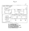
- Figure 4 is a block diagram showing an essential part of a monitor controller in the second embodiment according to the present invention.
- Figure 4 shows the configuration of the disaster prevention center 3.
- the disaster prevention center 3 is provided with a call registration device 24 in addition to the monitor 15, the intercommunication device 16, and the controller 17.
- the call registration device 24 is provided in order that an elevator (the control panel 2) is remotely operated in the disaster prevention center 3.
- the call registration device 24 is provided with changeover means 25, a plurality of destination call buttons 26 and the like.
- the changeover means 25 is intended for switching the call registration device 24 between a call registration function and a camera selection function.
- the changeover means 25 consists of, for example, a key switch, or a mechanical type or touch panel type operating button.
- the destination call button 26 is used in order that a destination call of an elevator is remotely registered in the disaster prevention center 3. That is, when the destination call button 26 is operated (pressed) by a monitoring staff member or other persons of the disaster prevention center 3, the call registration device 24 transmits a signal corresponding to the operated destination call button 26, and causes the registration of the destination call to be performed.
- the camera selection function is provided in order that a monitoring staff member or other persons of the disaster prevention center 3 are caused to manually perform the selection of the camera for causing the monitor 15 to indicate images.
- the destination call button 26 is used in order to select the camera which causes the monitor 15 to indicate images. That is, a monitoring staff member or other persons of the disaster prevention center 3 operate (press) the destination call button 26, whereby an image of the hall and/or an image of the inside of a car, which is photographed by the desired camera, can be caused to show up on the monitor 15.
- components of the monitor controller other than the disaster prevention center 3 are the same as in the first embodiment.
- FIG. 5 is a flowchart showing an essential part of the operations of the monitor controller in the second embodiment according to the present invention.
- S201 to S203 shown in Figure 5 correspond to S113 to S115 shown in Figure 2 . That is, each process shown in Figure 5 is performed after each process shown in S101 to S112 is performed.
- the indication selection means 22 makes a determination as to whether or not the call registration device 24 has been set at the camera selection function (S201).
- the automatic selection processing of the image indication camera is preferentially performed. That is, on the basis of the input information from each of the means in the controller 17 and the control panel 2 and the like, the indication selection means 22 performs a selection of the image indication camera and causes the monitor 15 to indicate an appropriate image suited to the present situation.
- the call registration device 24 is used in order that a monitoring staff member or other persons of the disaster prevention center 3 remotely register a destination call.
- the call registration device 24 is used in order that a monitoring staff member of the disaster prevention center 3 selects the camera which causes images to show up on the monitor 15.
- the indication selection means 22 performs a selection of the image indication camera and causes the monitor 15 to preferentially indicate an image by the selected camera (S203).
- the monitor 15 in the disaster prevention center 3 capable of performing the remote operation of an elevator, it is possible to cause the monitor 15 to indicate various kinds of information necessary for speedily and accurately performing evacuation operations. For this reason, a monitoring staff member of the disaster prevention center 3 can instantaneously grasp, from the indication contents of the monitor 15, information on the place where the fire has broken out in the building and information on the floor where those who are present in the building and require an evacuation by the elevator (for example, wheelchair users) are present, and the monitoring staff member becomes able to speedily and accurately perform rescue activities utilizing an elevator.
- the manual selection function for causing an image to show up on the monitor 15 can be provided in the call registration device 24, there is no concern of a device required for manual selection increasing in size. In other respects, the same effects as in the first embodiment can be produced.
- the monitor controller according to the present invention can be applied to a controller which controls a monitor installed in a prescribed remote place away from the car or hall of an elevator, such as a disaster prevention center.
Abstract
Description
- The present invention relates to a monitor controller which can appropriately control indications of a monitor installed in a disaster prevention center or the like.
- Patent Literature 1 below proposes an elevator for evacuation purposes utilized in rescue activities by firefighters when a fire breaks out in a building.
Specifically, in the monitor controller described in Patent Literature 1, the configuration is such that a camera is installed on each floor of a building and a monitor is installed in a car of an elevator so that it is possible to cause an image photographed by the camera to show up on the monitor in the car. In the case where the elevator is used for evacuation purposes during a fire, an operator (for example, a firefighter) performs the switching of camera images to show up on the monitor by operating a switch for selection installed in the car, thereby making sure of the situation in the hall. - Patent Literature 1: Japanese Patent Laid-Open No.
64-75378 - In the monitor controller described in Patent Literature 1, in the case where an elevator is used for evacuation purposes during a fire, an image of a hall photographed by a camera is caused to show up on a monitor in a car. This poses the problem that an operator in the car (for example, a firefighter) must perform various kinds of operations, such as operating the elevator and making sure of the situation in the hall, and hence it is impossible to perform rescue activities speedily and accurately.
- Incidentally, it cannot be said that information necessary for rescuing those who are present in a building is sufficiently provided only by causing an image of the hall photographed by the camera to show up on the monitor. Furthermore, in the monitor controller described in Patent Literature 1, an operator in the car must perform the switching of the image of the hall by himself or herself and, therefore, it is also difficult to cause an appropriate image of the hall to be indicated on the monitor.
- For example, an elevator utilized for evacuation purposes during a fire is often installed in a relatively high building. In such a building the number of floors at which an elevator stops is large and, therefore, the number of cameras installed in halls becomes large inevitably. For this reason, an operator in the car must make sure of the situation in each hall by sequentially switching images caused to show up on the monitor and this confirmation work requires much time. Furthermore, only with the images caused to show up on the monitor it may sometimes be difficult to identify the place where the fire has broken out and the like and it may be difficult to accurately grasp the present situation.
- The present invention was made in order to solve the problems described above and an object of the invention is to provide a monitor controller which can cause a monitor installed in a prescribed remote place to indicate various kinds of information. necessary for rescuing those who are present in a building in the case where an elevator is utilized for evacuation purposes during a fire.
- A monitor controller of the present invention is a monitor controller which comprises a monitor provided in a prescribed remote place away from a car and a hall of an elevator, indication control means which controls indications of the monitor, a first camera installed in the hall of the elevator, and operation control means which controls a normal operation of the elevator and an evacuation operation of the elevator during a fire. The indication control means causes the monitor to automatically indicate prescribed evacuation information including an image of the hall photographed by the first camera and information on a floor where the outbreak of a fire has been detected from fire detection information when the control of an evacuation operation is started by the operation control means.
- According to the present invention, in the case where an elevator is utilized for evacuation purposes during a fire, it becomes possible to cause a monitor installed in a prescribed remote place to indicate various kinds of information necessary for rescuing those who are present in a building. For this reason, when a fire has broken out in a building, it becomes possible to perform speedy and accurate rescue activities utilizing an elevator.
-
-
Figure 1 is a diagram showing the general configuration of a monitor controller in a first embodiment according to the present invention. -
Figure 2 is a flowchart showing the operations of the monitor controller in the first embodiment according to the present invention. -
Figure 3 is a diagram showing an example of an indication of a monitor in a disaster prevention center. -
Figure 4 is a block diagram showing an essential part of a monitor controller in a second embodiment according to the present invention. -
Figure 5 is a flowchart showing an essential part of the operations of the monitor controller in the second embodiment according to the present invention. - The present invention will be described in more detail with reference to the accompanying drawings. Incidentally, in each of the drawings, like numerals refer to like or corresponding parts and redundant descriptions of these parts are appropriately simplified or omitted.
-
Figure 1 is a diagram showing the general configuration of a monitor controller in a first embodiment according to the present invention.
InFigure 1 , reference numeral 1 denotes a car which ascends and descends in an elevator shaft, andreference numeral 2 denotes a control panel which performs the operation control of the whole elevator, such as the run control of the car 1. In normal times, thecontrol panel 2 performs, by the normal function thereof, normal services which involve causing the car 1 to respond successively to registered hall calls and car calls. In addition, this elevator has the function to be utilized for evacuation purposes in an emergency such as a fire, and thecontrol panel 2 also performs control for this purpose as required. -
Reference numeral 3 denotes adisaster prevention center 3 provided on the first floor or the like of a building in which the elevator is provided. Thedisaster prevention center 3 consists of a facility installed in a prescribed remote place away from the car 1 and an elevator hall, and performs the central control of disaster prevention equipment, fire extinguishing equipment and the like in the building or in a prescribed area (the premises, etc.). Each elevator in the building or each elevator in the prescribed area is collectively controlled in thisdisaster prevention center 3, and thecontrol panel 2 is connected to, for example, a central warning panel (not shown) of thedisaster prevention center 3. - In the building in which the elevator is provided, a
fire detector 4 is provided on each floor and acamera 5, anintercommunication device 6, and a rescue request button 7 (rescue request means) are provided in halls where the car 1 stops.
Thefire detector 4 has the function of detecting the outbreak of a fire from heat, smoke or the like. Upon detection of a fire, thefire detector 4 outputs information on the floor on which the fire has broken out, the place where the fire has broken out and the like as fire detection information to thedisaster prevention center 3. Incidentally, upon receipt of the fire detection information from thefire detector 4, thedisaster prevention center 3 outputs the received fire detection information (or information corresponding to the fire detection information) to thecontrol panel 2. - The
camera 5 is intended for photographing the situation in the hall. An image of each hall photographed by thecamera 5 is inputted to thedisaster prevention center 3. Theintercommunication device 6 is a device by use of which a person in the hall has a conversation with a monitoring staff member of thedisaster prevention center 3 and an operator in the can 1 (for example, a firefighter). Also theintercommunication device 6 is connected to thedisaster prevention center 3 as is thecamera 5. - The
rescue request button 7 is operated by those who are present in the building in making a request for a rescue by an elevator in an emergency such as a fire. Therescue request button 7 is connected directly to thecontrol panel 2 and outputs rescue request information to thecontrol panel 2 by being operated (pressed). Incidentally, rescue request information includes, for example, information to the effect that a rescue has been requested, and information on the floor where therescue request button 7 is installed. - In order to limit the operation of the
rescue request button 7 to specific persons (for example, wheelchair users and the elderly), therescue request button 7 may also have the function of an authentication device. For example, therescue request button 7 is configured in such a manner that the operation of therescue request button 7 becomes possible only in the case where personal authentication has been made by an authentication device. Also, therescue request button 7 may be configured in such a manner that a button operation is made unnecessary and when personal authentication has been made by an authentication device, rescue request information is automatically outputted to thecontrol panel 2. - The
camera 5,intercommunication device 6, andrescue request button 7 are installed, for example, in a plurality of halls at which the car 1 stops. These pieces of equipment may be installed in all halls at which the car 1 stops or may be installed only in a part of the halls. - A
camera 8 and anintercommunication device 9 are provided in the car 1 of an elevator.
Thecamera 8 is intended for photographing the situation in the car 1. An image of the inside of the car 1 photographed by thecamera 8 is inputted to thedisaster prevention center 3 via thecontrol panel 2. Theintercommunication device 9 is a device by use of which persons in the car 1 (a passenger, an operator and other persons) can communicate with the outside. Using thisintercommunication device 9, a person in the car I has conversations with a monitoring staff member of thedisaster prevention center 3 and a person who is using theintercommunication device 6 in the hall. Like thecamera 8 theintercommunication device 9 is also connected to thedisaster prevention center 3 via thecontrol panel 2. - The
control panel 2 has the function of controlling a normal operation for performing the normal services and an evacuation operation for performing an evacuation by an elevator when a fire has broken out in the building. Thecontrol panel 2 is connected to thedisaster prevention center 3, eachrescue request button 7, and (each piece of equipment of) the car 1, and the essential part thereof consists of, for example, communication means 10, operation control means 11, boarding detection means 12, rescue-requested floor detection means 13, and stop detection means 14. - The communication means 10 is provided in order that the
control panel 2 performs the sending and receiving of information with each piece of connected equipment. - The operation control means 11 has the function of controlling various kinds of operations of an elevator, such as a normal operation and an evacuation operation during a fire. The operation control means 11 performs a normal operation in normal times and performs control which involves causing the car 1 to respond successively to registered hall calls and car calls. When the outbreak of a fire has been detected by any of the
fire detectors 4, the operation control means 11 starts prescribed control necessary for performing a rescue of those who are present in the building by switching the elevator from a normal operation to an evacuation operation in the case where prescribed start conditions are satisfied. - The boarding detection means 12 has the function of detecting persons in the car 1. On the basis of an output of, for example, a load weighing device and a sensor (an infrared sensor or the like) provided in the car 1 and the like, or an image photographed by the
camera 8, the boarding detection means 12 makes a determination as to whether or not a person is present in the car 1, and detects that a person is present in the car I in the case where prescribed conditions are satisfied. When the boarding detection means 12 has detected the presence of a person in the car 1, the boarding detection means 12 outputs the result also to thedisaster prevention center 3 via the communication means 10. - The rescue-requested floor detection means 13 has the function of detecting the floor on which a rescue request has been performed (the rescue-requested floor) on the basis of the rescue request information received from the
rescue request button 7. When the rescue-requested floor detection means 13 identifies the rescue-requested floor on the basis of the received rescue request information, the rescue-requested floor detection means 13 outputs the result also to thedisaster prevention center 3 via the communication means 10. - The stop detection means 14 has the function of detecting a prescribed landing determination for stopping the car 1 during a run. A prescribed landing determination, such as a deceleration instruction to an elevator traction machine, becomes necessary for stopping the car 1 during a run. The stop detection means 14 detects that such a landing determination has been made, and identifies the floor at which the car 1 stops. When the stop detection means 14 identifies the floor at which the car 1 stops next, the stop detection means 14 outputs the result also to the
disaster prevention center 3 via the communication means 10. - On the other hand, the
disaster prevention center 3 is provided with amonitor 15, anintercommunication device 16, acontroller 17, and manual changeover means 18. - The
monitor 15 is indented for providing monitoring information of an elevator, disaster prevention information of the building and the like to a monitoring staff member or other persons of thedisaster prevention center 3, and consists of, for example, a liquid crystal display. In normal times, general monitoring information is indicated on themonitor 15. When a fire has broken out in the building and an evacuation operation for performing an evacuation by an elevator is started in thecontrol panel 2, under prescribed conditions, various kinds of information necessary for speedily and accurately performing an evacuation operation (hereinafter referred to as "evacuation information") is indicated on themonitor 15. Specifically, various kinds of information necessary for supporting rescue activities utilizing an elevator is indicated as evacuation information on themonitor 15 of thedisaster prevention center 3.
As described above, both general monitoring information and evacuation information are indicated on themonitor 15 by being switched therebetween, whereby themonitor 15 is effectively utilized and the number ofmonitors 15 can be reduced.
Incidentally, concrete indication contents of themonitor 15 during an evacuation operation will be described later. - The
intercommunication device 16 is a device by use of which a monitoring staff member or other persons of thedisaster prevention center 3 can communicate with the outside. That is, when an evacuation operation is being performed on thecontrol panel 2, the monitoring staff member of thedisaster prevention center 3 has conversations with persons in the car 1 (a passenger, an operator and other persons) and a person who is using anintercommunication device 6 in the hall. - The
controller 17 is provided in the central warning panel or the like of thedisaster prevention center 3. Thedisaster prevention center 3 has the function of causing themonitor 15 to indicate images photographed by thecameras camera 5 and/or thecamera 8 which causes themonitor 15 to indicate an image can be performed automatically or manually as required. In order to realize such a function, thecontroller 17 is provided with communication means 19, fire information detection means 20, indication control means 21, indication selection means 22, and intercommunication selection means 23. - The communication means 19 is provided in order that the
disaster prevention center 3 performs the sending and receiving of information with each piece of connected equipment.
The fire information detection means 20 has the function of detecting the floor where a fire has broken out and a place where a fire has broken out on the basis of the fire detection information received from thefire detector 4. - The indication control means 21 has the function of controlling indications of the
monitor 15 installed in thedisaster prevention center 3. In normal times when a normal operation is performed in an elevator, the indication control means 21 causes themonitor 15 to indicate general monitoring information, such as the state of each piece of equipment installed in the building and the state of an elevator. On the other hand, when the control of an evacuation operation is started on the control panel 2 (by the operation control means 11), the indication control means 21 causes themonitor 15 to automatically indicate the evacuation information on the basis of information from thecontrol panel 2, information from other means in thecontroller 17 and the like. - The indication selection means 22 has the function of selecting the camera for causing the
monitor 15 to indicate an image (hereinafter referred to also as the "image indication camera") from thecameras 5 installed in a plurality of halls and thecamera 8 installed in the car 1. That is, the indication control means 21 causes themonitor 15 to indicate in real time images photographed by thecamera 5 and/or thecamera 8 selected by the indication selection means 22.
Incidentally, image indication cameras selected by the indication selection means 22 may be one camera or may be a plurality of cameras (for example, 2 cameras, 4 cameras or the like). - For example, when the outbreak of a fire is detected by the
fire detector 4, the indication selection means 22 selects thecamera 5 installed on the floor where the fire has broken out as the image indication camera on the basis of the detection result of the fire information detection means 20. As a result of this, an image of the hall on the floor where the fire has broken out is caused to show up automatically on themonitor 15 of thedisaster prevention center 3. When the floor where the fire has broken out and/or the place where the fire has broken out has been identified by the fire information detection means 20, the indication control means 21 causes themonitor 15 to indicate the information on the identified floor where the fire has broken out and the like as evacuation information. - Furthermore, for example, when the
rescue request button 7 is operated in a hall of the elevator and a rescue request is performed, the indication selection means 22 selects thecamera 5 installed on the rescue-requested floor as the image indication camera on the basis of the detection result of the rescue-requested floor detection means 13 of thecontrol panel 2. As a result of this, an image of the hall of the rescue-requested floor is caused to show up automatically on themonitor 15. Besides, when the rescue-requested floor is identified by the rescue-requested floor detection means 13, the indication control means 21 causes themonitor 15 to indicate the information on the identified rescue-requested floor as evacuation information. - Moreover, for example, when a landing determination is detected by the stop detection means 14 of the
control panel 2 as in the case where during an evacuation operation the car 1 stops at a rescue floor, the indication selection means 22 selects thecamera 5 installed on the floor at which the car 1 is to stop as the image indication camera. As a result of this, an image of the hall of the rescue floor at which the car 1 stops immediately thereafter is caused to show up automatically. - Furthermore, for example, when the presence of a person in the car 1 is detected by the boarding detection means 12 when an evacuation operation of an elevator is being performed, the indication selection means 22 selects the
camera 8 installed in the car 1 as the image indication camera. As a result of this, an image of the inside of the car 1 is caused to show up automatically. - The intercommunication selection means 23 has the function of detecting the channel of the
intercommunication device 16 of thedisaster prevention center 3.
When theintercommunication device 16 has selected the channel of either theintercommunication device 6 or theintercommunication device 9, on the basis of the detection result of the intercommunication selection means 23, the indication selection means 22 selects the camera in the place where the channel-selected intercommunication device is installed as the image indication camera. For example, when theintercommunication device 16 has selected the channel of one of theintercommunication devices 6, the indication selection means 22 selects thecamera 5 of the floor where theintercommunication device 6 is installed as the image indication camera. As a result of this, an image of the hall of the floor on which the channel-selectedintercommunication device 6 is installed is caused to show up automatically on themonitor 15. When theintercommunication device 16 has selected the channel of theintercommunication device 9, the indication selection means 22 selects thecamera 8 as the image indication camera. As a result of this, an image of the inside of the car 1 is caused to show up automatically on themonitor 15. - The manual changeover means 18 is provided in order to cause a monitoring staff member or other persons of the
disaster prevention center 3 to manually perform the selection of the camera which causes themonitor 15 to indicate images. That is, the monitoring staff member of thedisaster prevention center 3 selects one or more ofcamera 5 and/orcamera 8 by the manual changeover means 18, thereby enabling an image of the hall and/or an image of the inside of a car photographed by a desired camera to show up on themonitor 15. - Next, referring also to
Figures 2 and3 , the operations of the monitor controller having the above-described configuration will be described concretely.Figure 2 is a flowchart showing the operations of the monitor controller in the first embodiment according to the present invention, andFigure 3 is a diagram showing an example of an indication of the monitor in the disaster prevention center. - When the outbreak of a fire is detected by any of the
fire detectors 4 in the building while a normal operation is being performed in an elevator, the fire detection information from thefire detector 4 is inputted to thedisaster prevention center 3. In thecontroller 17 of thedisaster prevention center 3, upon receipt of the fire detection information by the communication means 19, the outbreak of the fire is made sure of (S101) and the processing shown below is performed. - In the
controller 17, first, a determination is made as to whether or not an evacuation utilizing an elevator during a fire is possible (S102).
The fire detection information from thefire detector 4 is inputted also to theelevator control panel 2 via thedisaster prevention center 3. The start conditions for utilizing an elevator during a fire are stored beforehand in thecontrol panel 2, and by comparing the present state of the elevator with the start conditions, the operation control means 11 makes a determination as to whether or not a changeover to an evacuation operation is possible. For example, in the case where the start conditions do not hold as in the case where a prescribed safety device is in operation, an evacuation operation is not started in the elevator. In this case, a determination is made in thecontroller 17 that the elevator cannot be utilized (No in S102), and the indication control means 21, for example, causes the indication of general monitoring information to be continued. - On the other hand, when the start conditions have held at the time of receipt of the fire detection information, the operation control means 11 causes the elevator to make a changeover from a normal operation to an evacuation operation. In the
disaster prevention center 3, by detecting this changeover to an evacuation operation, in S102 a determination is made that the elevator can be utilized. In thedisaster prevention center 3 the monitor control for supporting rescue activities utilizing the elevator is started in thecontroller 17. - In the indication control means 21, because of the detection of the switching to an evacuation operation the indication contents of the
monitor 15 are changed from the existing general monitoring information to evacuation information during a fire (S103). For example, in the case where the monitor controller has the configuration shown inFigure 1 , the indication control means 21 causes themonitor 15 to indicate, as evacuation information during a fire, an image of the hall by thecamera 5 and an image of the inside of the car by thecamera 8, as well as the information on the floor where the fire has broken out, the place where the fire has broken out, and the rescue-requested floor (S104). - Incidentally, images caused to show up on the
monitor 15 are those photographed by thecamera 5 and/orcamera 8 selected by the indication selection means 22 as the image indication camera. An evacuation operation during a fire is started when thefire detector 4 detects the outbreak of a fire. For this reason, immediately after the start of an evacuation operation (i.e., in S104), thecamera 5 of the floor where the fire has broken out is selected by the indication selection means 22 as the image indication camera and at least an image of the hall of the floor where the fire has broken out is caused to show up on themonitor 15. - When in S104 the initial evacuation information is indicated on the
monitor 15, the indication selection means 22 makes a determination as to whether or not theintercommunication device 16 of thedisaster prevention center 3 has selected the channel of any of theintercommunication devices 6 installed in a hall (S105). When intercommunication between thedisaster prevention center 3 and the hall has been established, the indication selection means 22 selects thecamera 5 of the floor where theintercommunication device 6 whose channel has been selected by theintercommunication device 16 is installed as the image indication camera, and causes themonitor 15 to preferentially indicate an image of the hall (S106). - In the case where intercommunication between the
disaster prevention center 3 and the hall has not been established, next, a determination is made as to whether or not theintercommunication device 16 of thedisaster prevention center 3 has selected the channel of theintercommunication device 9 installed in the car 1 (S107). When intercommunication between thedisaster prevention center 3 and the car 1 has been established, the indication selection means 22 selects thecamera 8 in the car 1 as the image indication camera, and causes themonitor 15 to preferentially indicate an image of the inside of the car (S108). - On the other hand, in the case where channel selection of any
intercommunication device 9 by the intercommunication selection means 23 has not been detected (No in S107), next, the indication selection means 22 makes a determination as to whether or not arescue request button 7 of a hall has been operated (S109). If any of therescue request buttons 7 has been operated, the indication selection means 22 selects thecamera 5 of the floor where the operatedrescue request button 7 is installed as the image indication camera, and causes themonitor 15 to preferentially indicate an image of the hall (S110). -
Figure 3 shows an example of an indication of themonitor 15 in S110. In the example shown inFigure 3 , whether or not a rescue request has been performed is indicated for each floor on themonitor 15. Thecamera 5 of the 5th floor for which arescue request button 7 was operated is selected as the image indication camera, and an image of the hall of the 5th floor is indicated on themonitor 15. Incidentally, in the example shown inFigure 3 , arescue request button 7 of the 3rd floor is also operated. In this case, the indication selection means 22 may select bothcameras 5 of the 3rd floor and the 5th floor as the image indication camera and an image of the hall of the 3rd floor and an image of the hall of the 5th floor may be indicated by split-screen display or may be indicated alternately in a prescribe region of themonitor 15. Furthermore, the indication selection means 22 may select thecamera 5 of the floor where arescue request button 7 operated later is installed as the image indication camera. -
Figure 3 shows an example in which the manual changeover means 18 is caused to show up on themonitor 15. As in this example, the manual changeover means 18 may be composed of a touch panel type button so that the manual selection of cameras can be performed in themonitor 15. - In the case where neither the channel selection by the
intercommunication device 16 nor a rescue request by therescue request button 7 has been performed (No in S109), next, the indication selection means 22 makes a determination as to whether or not a landing determination of an elevator has been made (S111). When it has been determined that the elevator stops at the rescue floor, the indication selection means 22 selects thecamera 5 on the floor where the car 1 stops next as the image indication camera, and causes themonitor 15 to preferentially indicate an image of the hall (S112). - After in S106, S108, S110, and S112 the
monitor 15 is caused to indicate a new image of the hall or a new image of the inside of a car or after in S111 a determination is made to the effect that a landing determination has not been made, the indication selection means 22 makes a determination as to whether or not the manual selection of a camera has been performed by the manual changeover means 18 (S113). Incidentally, in the case where no operation has been performed on the manual changeover means 18 (S114), the automatic selection processing of the image indication camera shown in the above-described S104 to S112 is preferentially performed and an appropriate image suited to the present situation is indicated on themonitor 15. - On the other hand, when the selection of a camera is performed by the manual changeover means 18 as in the case where the touch panel type input button shown in
Figure 3 is pressed, the indication selection means 22 selects the camera 5 (of the floor) identified by the manual changeover means 18 as the image indication camera, and causes themonitor 15 to preferentially indicate an image of the hall (S115). Incidentally, in the case where the outbreak of a fire, a channel selection by theintercommunication device 16, a rescue request, a landing determination and the like have been newly detected even after the manual selection of a camera by the manual changeover means 18 is performed, a switching of the indication of themonitor 15 may be performed by preferentially performing the automatic selection processing of the image indication camera. - According to the first embodiment according to the present invention, in the case where an elevator is utilized for evacuation purposes during a fire, it is possible to cause the
monitor 15 of thedisaster prevention center 3 to indicate various kinds of information necessary for rescuing those who are present in a building by an elevator (that is, in order to support rescue activities utilizing an elevator). That is, a monitoring staff member of thedisaster prevention center 3 can instantaneously grasp, from the indication contents of themonitor 15, information on the place where the fire has broken out in the building and information on the floor where those who are present in the building and require an evacuation by the elevator (for example, wheelchair users) are present. As a result of this, the monitoring staff member of thedisaster prevention center 3 can give appropriate instructions to an operator and other persons in the car 1, making it possible to realize speedy and accurate rescue activities utilizing the elevator. - In a high-rise building, the number of cameras installed in halls becomes inevitably large. However, with a monitor controller of the above-described configuration, it is possible to cause the
monitor 15 to indicate appropriate images according to the situation in the building and the presence or absence of those who are present in the building. - Incidentally, in this embodiment, concrete descriptions were given of the case where the
monitor 15 is caused to indicate an image of the hall by thecamera 5 and an image of the inside of the car 1 by thecamera 8, as well as each information on the floor where a fire has broken out, the place where a fire has broken out and a rescue-requested floor as evacuation information during a fire. However, in the case where information on a specific place where a fire has broken out is not included in fire detection information from thefire detector 4, only information on the floor where a fire has broken out may be indicated on themonitor 15. In the case where therescue request button 7 is not installed in the hall of an elevator, information on a rescue-requested floor is not included in the evacuation information, and it is necessary only that other information be indicated on themonitor 15. Furthermore, themonitor 15 may be caused to constantly indicate an image of the inside of the car by thecamera 8 as evacuation information and themonitor 15 may be caused to indicate this information as required (according to the detection result of each means). Furthermore, in the case where thecamera 8 is not installed in the car 1, an image of the inside of the car is not included in the evacuation information and it is necessary only that other information be indicated on themonitor 15. - In this embodiment, the case where the
monitor 15 and thecontroller 17 are installed in thedisaster prevention center 3 was described concretely. However, this is only an example, and the installation place of themonitor 15 may be any place so long as this place is away from the car 1 and halls and is a place where rescue activities utilizing an elevator can be supported. For example, it is possible that themonitor 15, theintercommunication device 16, thecontroller 17 and the like are provided in monitoring centers run by an elevator maintenance company, nearby facilities related to firefighting, facilities related to firefighting which are temporarily installed in an emergency and the like. -
Figure 4 is a block diagram showing an essential part of a monitor controller in the second embodiment according to the present invention.Figure 4 shows the configuration of thedisaster prevention center 3.
Thedisaster prevention center 3 is provided with acall registration device 24 in addition to themonitor 15, theintercommunication device 16, and thecontroller 17. Thecall registration device 24 is provided in order that an elevator (the control panel 2) is remotely operated in thedisaster prevention center 3. Thecall registration device 24 is provided with changeover means 25, a plurality ofdestination call buttons 26 and the like. - The changeover means 25 is intended for switching the
call registration device 24 between a call registration function and a camera selection function. The changeover means 25 consists of, for example, a key switch, or a mechanical type or touch panel type operating button. - In the case where the
call registration device 24 is set at the call registration function by the changeover means 25, thedestination call button 26 is used in order that a destination call of an elevator is remotely registered in thedisaster prevention center 3. That is, when thedestination call button 26 is operated (pressed) by a monitoring staff member or other persons of thedisaster prevention center 3, thecall registration device 24 transmits a signal corresponding to the operateddestination call button 26, and causes the registration of the destination call to be performed. - On the other hand, the camera selection function is provided in order that a monitoring staff member or other persons of the
disaster prevention center 3 are caused to manually perform the selection of the camera for causing themonitor 15 to indicate images.
In the case where thecall registration device 24 is set at the camera selection function by the changeover means 25, thedestination call button 26 is used in order to select the camera which causes themonitor 15 to indicate images. That is, a monitoring staff member or other persons of thedisaster prevention center 3 operate (press) thedestination call button 26, whereby an image of the hall and/or an image of the inside of a car, which is photographed by the desired camera, can be caused to show up on themonitor 15. - Incidentally, components of the monitor controller other than the
disaster prevention center 3 are the same as in the first embodiment. - Next, referring also to
Figure 5 , a concrete description will be given of the operations of the monitor controller having the above-described configuration.Figure 5 is a flowchart showing an essential part of the operations of the monitor controller in the second embodiment according to the present invention. Incidentally, S201 to S203 shown inFigure 5 correspond to S113 to S115 shown inFigure 2 . That is, each process shown inFigure 5 is performed after each process shown in S101 to S112 is performed. - In S201, the indication selection means 22 makes a determination as to whether or not the
call registration device 24 has been set at the camera selection function (S201). Incidentally, in the case where thecall registration device 24 has been set at the call registration function (S202), the automatic selection processing of the image indication camera is preferentially performed. That is, on the basis of the input information from each of the means in thecontroller 17 and thecontrol panel 2 and the like, the indication selection means 22 performs a selection of the image indication camera and causes themonitor 15 to indicate an appropriate image suited to the present situation. In this case, thecall registration device 24 is used in order that a monitoring staff member or other persons of thedisaster prevention center 3 remotely register a destination call. - On the other hand, in the case where the
call registration device 24 has been set at the camera selection function (Yes in S201), thecall registration device 24 is used in order that a monitoring staff member of thedisaster prevention center 3 selects the camera which causes images to show up on themonitor 15. In this case, on the basis of the operation performed on thedestination call button 26 of the call registration device 24 (i.e., the pressed destination call button 26), the indication selection means 22 performs a selection of the image indication camera and causes themonitor 15 to preferentially indicate an image by the selected camera (S203). - According to the second embodiment according to the present invention, in the
disaster prevention center 3 capable of performing the remote operation of an elevator, it is possible to cause themonitor 15 to indicate various kinds of information necessary for speedily and accurately performing evacuation operations. For this reason, a monitoring staff member of thedisaster prevention center 3 can instantaneously grasp, from the indication contents of themonitor 15, information on the place where the fire has broken out in the building and information on the floor where those who are present in the building and require an evacuation by the elevator (for example, wheelchair users) are present, and the monitoring staff member becomes able to speedily and accurately perform rescue activities utilizing an elevator. - Because the manual selection function for causing an image to show up on the
monitor 15 can be provided in thecall registration device 24, there is no concern of a device required for manual selection increasing in size.
In other respects, the same effects as in the first embodiment can be produced. - The monitor controller according to the present invention can be applied to a controller which controls a monitor installed in a prescribed remote place away from the car or hall of an elevator, such as a disaster prevention center.
-
Reference Signs List 1 car 2 control panel 3 disaster prevention center 4 fire detector 5, 8 camera 6, 9, 16 intercommunication device 7 rescue request button 10, 19 communication means 11 operation control means 12 boarding detection means 13 rescue-requested floor detection means 14 stop detection means 15 monitor 17 controller 18 manual changeover means 20 fire information detection means 21 indication control means 22 indication selection means 23 intercommunication selection means 24 call registration device 25 changeover means 26 destination call button
Claims (14)
- A monitor controller, comprising:a monitor provided in a prescribed remote place away from a car and a hall of an elevator;indication control means which controls indications of the monitor;a first camera installed in the hall of the elevator; andoperation control means which controls a normal operation of the elevator and an evacuation operation of the elevator during a fire,wherein the indication control means causes the monitor to automatically indicate prescribed evacuation information including an image of the hall photographed by the first camera and information on a floor where the outbreak of a fire has been detected from fire detection information when the control of an evacuation operation is started by the operation control means.
- The monitor controller according to claim 1, further comprising:a second camera installed in the car,wherein the indication control means causes the monitor to automatically indicate an image of the inside of the car photographed by the second camera as required when the control of an evacuation operation is started by the operation control means.
- The monitor controller according to claim 2, further comprising:indication selection means which selects a camera causing the monitor to indicate an image from first cameras installed in a plurality of halls at which the car stops and a second camera provided in the car,wherein the indication control means causes the monitor to indicate an image photographed by the camera selected by the indication selection means when the control of an evacuation operation is started by the operation control means.
- The monitor controller according to claim 1, further comprising:indication selection means which selects a camera causing the monitor to indicate an image from first cameras installed in a plurality of halls at which the car stops,wherein the indication control means causes the monitor to indicate an image of the hall photographed by the camera selected by the indication selection means when the control of an evacuation operation is started by the operation control means.
- The monitor controller according to claim 3 or 4, wherein the indication selection means selects a first camera installed on the floor where a fire has broken out as a camera which causes the monitor to indicate an image when the outbreak of the fire has been detected from the fire detection information.
- The monitor controller according to any of claims 3 to 5, further comprising:a first intercommunication device provided in the remote place, anda second intercommunication device provided in the hall of the elevator,wherein the indication selection means selects a first camera on the floor where the second intercommunication device is installed as a camera which causes the monitor to indicate an image when the first intercommunication device has selected the channel of the second intercommunication device.
- The monitor controller according to any of claims 3 to 5, further comprising:rescue request means which is provided in the hall of the elevator and is intended for use in requesting a rescue by the elevator,wherein the indication selection means selects a first camera installed on a rescue-requested floor as a camera which causes the monitor to indicate an image when a request for a rescue has been performed by the rescue request means.
- The monitor controller according to claim 7, wherein the indication control means causes the monitor to automatically indicate information on the rescue-requested floor as the evacuation information when a request for a rescue has been performed by the rescue request means.
- The monitor controller according to any of claims 3 to 5, further comprising:stop detection means which detects a prescribed landing determination for stopping the car during a run,wherein the indication selection means selects a first camera installed on a floor at which the car is to stop as a camera which causes the monitor to indicate an image when a landing determination has been detected by the stop detection means.
- The monitor controller according to claim 3, further comprising:a first intercommunication device provided in the remote place; anda third intercommunication device provided in the car,wherein the indication selection means selects the second camera as a camera which causes the monitor to indicate an image when the first intercommunication device has selected the channel of the third intercommunication device.
- The monitor controller according to claim 3, further comprising:boarding detection means for detecting persons in the car,wherein the indication selection means selects the second camera as a camera which causes the monitor to indicate an image when the presence of a person has been detected by the boarding detection means.
- The monitor controller according to any of claims 3 to 11, further comprising:a call registration device provided in the remote place, whereinthe call registration device has a plurality of destination call buttons for remotely registering a destination call; andthe indication selection means performs selection of a camera which causes the monitor to indicate an image on the basis of an operation performed on the destination call buttons.
- The monitor controller according to claim 12, further comprising:changeover means which is provided in the remote place and switches the call registration device between a call registration function and a camera selection function, whereinthe call registration device performs remote registration of a destination call on the basis of an operation on the destination call buttons when the call registration function has been set by the changeover means, andthe indication selection means performs selection of a camera which causes the monitor to indicate an image on the basis of an operation on the destination call buttons when the call registration device has been set at the camera selection function by the changeover means.
- The monitor controller according to any of claims 1 to 13, wherein the monitor is installed in any of a disaster prevention center which performs the control of elevators, a monitoring center of an elevator maintenance company, and a prescribed facility related to firefighting.
Applications Claiming Priority (1)
| Application Number | Priority Date | Filing Date | Title |
|---|---|---|---|
| PCT/JP2010/064474 WO2012026016A1 (en) | 2010-08-26 | 2010-08-26 | Monitor control device |
Publications (3)
| Publication Number | Publication Date |
|---|---|
| EP2610203A1 true EP2610203A1 (en) | 2013-07-03 |
| EP2610203A4 EP2610203A4 (en) | 2017-10-25 |
| EP2610203B1 EP2610203B1 (en) | 2018-10-24 |
Family
ID=45723043
Family Applications (1)
| Application Number | Title | Priority Date | Filing Date |
|---|---|---|---|
| EP10856420.4A Active EP2610203B1 (en) | 2010-08-26 | 2010-08-26 | Monitor control device |
Country Status (5)
| Country | Link |
|---|---|
| EP (1) | EP2610203B1 (en) |
| JP (1) | JP5516743B2 (en) |
| KR (1) | KR101436769B1 (en) |
| CN (1) | CN103108823B (en) |
| WO (1) | WO2012026016A1 (en) |
Cited By (3)
| Publication number | Priority date | Publication date | Assignee | Title |
|---|---|---|---|---|
| US11312594B2 (en) | 2018-11-09 | 2022-04-26 | Otis Elevator Company | Conveyance system video analytics |
| WO2022161642A1 (en) * | 2021-02-01 | 2022-08-04 | Kone Corporation | An application server associated with an elevator communication system, an elevator system and a method |
| WO2022161641A1 (en) * | 2021-02-01 | 2022-08-04 | Kone Corporation | Elevator communication system, a method and an apparatus |
Families Citing this family (11)
| Publication number | Priority date | Publication date | Assignee | Title |
|---|---|---|---|---|
| CN103803361A (en) * | 2013-12-27 | 2014-05-21 | 广州永日电梯有限公司 | Monitoring method based on wireless transmission |
| JP6350745B2 (en) * | 2015-05-18 | 2018-07-04 | 三菱電機株式会社 | Elevator control system |
| JP6705683B2 (en) * | 2016-03-30 | 2020-06-03 | 株式会社竹中工務店 | Building and evacuation guidance method in the building |
| US10227209B2 (en) | 2016-04-06 | 2019-03-12 | Otis Elevator Company | Orchestration of an occupant evacuation operation using destination entry fixtures |
| US10011460B2 (en) | 2016-09-27 | 2018-07-03 | Otis Elevator Company | Elevator dynamic displays for messaging and communication |
| US20180093858A1 (en) * | 2016-09-30 | 2018-04-05 | Otis Elevator Company | Method for occupant evacuation operation utilizing multi-compartment elevators |
| CN106448036A (en) * | 2016-11-01 | 2017-02-22 | 合肥华贝信息科技有限公司 | Intelligent building security monitoring system |
| CN106882669A (en) * | 2017-04-14 | 2017-06-23 | 安徽省沃瑞网络科技有限公司 | A kind of residential elevator control system based on fire alarm |
| CN106966249B (en) * | 2017-06-01 | 2023-03-31 | 深圳金三立视频科技股份有限公司 | Elevator monitoring system |
| EP3483103B1 (en) | 2017-11-08 | 2023-12-27 | Otis Elevator Company | Emergency monitoring systems for elevators |
| CN110304514A (en) * | 2019-07-15 | 2019-10-08 | 广州广日电梯工业有限公司 | Elevator fire-fighting interlock method and system |
Family Cites Families (8)
| Publication number | Priority date | Publication date | Assignee | Title |
|---|---|---|---|---|
| JPS6475378A (en) | 1987-09-14 | 1989-03-22 | Toshiba Corp | Controller for elevator for emergency |
| JPH052693A (en) * | 1991-06-25 | 1993-01-08 | Tetsuya Muraoka | Fire emergency evacuation guidance system for building such as hotel |
| JPH07215617A (en) * | 1994-02-03 | 1995-08-15 | Toshiba Fa Syst Eng Kk | Elevator crime prevention/monitoring device |
| KR100347300B1 (en) * | 1999-12-24 | 2002-08-07 | (주) 세이프 씨스템 | Automatic Fire Detection Device Using Video Image |
| JP2006008332A (en) * | 2004-06-25 | 2006-01-12 | Mitsubishi Electric Corp | Security device for elevator |
| JP4772457B2 (en) * | 2005-11-08 | 2011-09-14 | 三菱電機株式会社 | Elevator evacuation operation device |
| JP2008189413A (en) * | 2007-02-02 | 2008-08-21 | Nippon Otis Elevator Co | Emergency call device for elevator |
| CN102119114A (en) * | 2008-08-27 | 2011-07-06 | 三菱电机株式会社 | Evacuation assistance system |
-
2010
- 2010-08-26 CN CN201080068106.5A patent/CN103108823B/en active Active
- 2010-08-26 JP JP2012530480A patent/JP5516743B2/en active Active
- 2010-08-26 WO PCT/JP2010/064474 patent/WO2012026016A1/en active Application Filing
- 2010-08-26 KR KR1020137005047A patent/KR101436769B1/en active IP Right Grant
- 2010-08-26 EP EP10856420.4A patent/EP2610203B1/en active Active
Non-Patent Citations (1)
| Title |
|---|
| See references of WO2012026016A1 * |
Cited By (3)
| Publication number | Priority date | Publication date | Assignee | Title |
|---|---|---|---|---|
| US11312594B2 (en) | 2018-11-09 | 2022-04-26 | Otis Elevator Company | Conveyance system video analytics |
| WO2022161642A1 (en) * | 2021-02-01 | 2022-08-04 | Kone Corporation | An application server associated with an elevator communication system, an elevator system and a method |
| WO2022161641A1 (en) * | 2021-02-01 | 2022-08-04 | Kone Corporation | Elevator communication system, a method and an apparatus |
Also Published As
| Publication number | Publication date |
|---|---|
| WO2012026016A1 (en) | 2012-03-01 |
| CN103108823A (en) | 2013-05-15 |
| KR20130045367A (en) | 2013-05-03 |
| EP2610203A4 (en) | 2017-10-25 |
| KR101436769B1 (en) | 2014-09-01 |
| CN103108823B (en) | 2015-04-08 |
| EP2610203B1 (en) | 2018-10-24 |
| JPWO2012026016A1 (en) | 2013-10-28 |
| JP5516743B2 (en) | 2014-06-11 |
Similar Documents
| Publication | Publication Date | Title |
|---|---|---|
| EP2610203A1 (en) | Monitor control device | |
| EP2610202A1 (en) | Monitor control device for elevator | |
| JP5452505B2 (en) | Elevator system | |
| US7938232B2 (en) | Evacuation control apparatus for an elevator | |
| JP2007161417A (en) | Elevator device | |
| WO2011052090A1 (en) | Notification device of elevator | |
| KR20120084959A (en) | Elevator sytem and method of controlling the same | |
| JP2015224116A (en) | Elevator rescue operation device | |
| CN114728758A (en) | Elevator control system and elevator control method | |
| JP6624522B2 (en) | Remote monitoring system for lifting equipment | |
| JP2015074521A (en) | Safety device for inspection work of elevator | |
| JP2012126559A (en) | Elevator system and operation control method of the same | |
| JP5546223B2 (en) | Elevator system | |
| WO2022059097A1 (en) | Elevator emergency contact system | |
| WO2019064371A1 (en) | Landing destination floor input device for elevators, elevator control system, and elevator system | |
| WO2022059096A1 (en) | Emergency communication system for elevator | |
| JP2011116530A (en) | Elevator system | |
| JP2012144330A (en) | Elevator system and its control method | |
| JP2012126469A (en) | Elevator | |
| JP2015020835A (en) | Elevator system |
Legal Events
| Date | Code | Title | Description |
|---|---|---|---|
| PUAI | Public reference made under article 153(3) epc to a published international application that has entered the european phase |
Free format text: ORIGINAL CODE: 0009012 |
|
| 17P | Request for examination filed |
Effective date: 20121219 |
|
| AK | Designated contracting states |
Kind code of ref document: A1 Designated state(s): AL AT BE BG CH CY CZ DE DK EE ES FI FR GB GR HR HU IE IS IT LI LT LU LV MC MK MT NL NO PL PT RO SE SI SK SM TR |
|
| DAX | Request for extension of the european patent (deleted) | ||
| RA4 | Supplementary search report drawn up and despatched (corrected) |
Effective date: 20170925 |
|
| RIC1 | Information provided on ipc code assigned before grant |
Ipc: B66B 3/00 20060101ALI20170919BHEP Ipc: B66B 5/02 20060101AFI20170919BHEP |
|
| GRAP | Despatch of communication of intention to grant a patent |
Free format text: ORIGINAL CODE: EPIDOSNIGR1 |
|
| STAA | Information on the status of an ep patent application or granted ep patent |
Free format text: STATUS: GRANT OF PATENT IS INTENDED |
|
| INTG | Intention to grant announced |
Effective date: 20180702 |
|
| GRAS | Grant fee paid |
Free format text: ORIGINAL CODE: EPIDOSNIGR3 |
|
| GRAA | (expected) grant |
Free format text: ORIGINAL CODE: 0009210 |
|
| STAA | Information on the status of an ep patent application or granted ep patent |
Free format text: STATUS: THE PATENT HAS BEEN GRANTED |
|
| AK | Designated contracting states |
Kind code of ref document: B1 Designated state(s): AL AT BE BG CH CY CZ DE DK EE ES FI FR GB GR HR HU IE IS IT LI LT LU LV MC MK MT NL NO PL PT RO SE SI SK SM TR |
|
| REG | Reference to a national code |
Ref country code: GB Ref legal event code: FG4D |
|
| REG | Reference to a national code |
Ref country code: CH Ref legal event code: EP |
|
| REG | Reference to a national code |
Ref country code: IE Ref legal event code: FG4D |
|
| REG | Reference to a national code |
Ref country code: AT Ref legal event code: REF Ref document number: 1056430 Country of ref document: AT Kind code of ref document: T Effective date: 20181115 |
|
| REG | Reference to a national code |
Ref country code: DE Ref legal event code: R096 Ref document number: 602010054674 Country of ref document: DE |
|
| REG | Reference to a national code |
Ref country code: NL Ref legal event code: MP Effective date: 20181024 |
|
| REG | Reference to a national code |
Ref country code: LT Ref legal event code: MG4D |
|
| REG | Reference to a national code |
Ref country code: AT Ref legal event code: MK05 Ref document number: 1056430 Country of ref document: AT Kind code of ref document: T Effective date: 20181024 |
|
| PG25 | Lapsed in a contracting state [announced via postgrant information from national office to epo] |
Ref country code: NL Free format text: LAPSE BECAUSE OF FAILURE TO SUBMIT A TRANSLATION OF THE DESCRIPTION OR TO PAY THE FEE WITHIN THE PRESCRIBED TIME-LIMIT Effective date: 20181024 |
|
| PG25 | Lapsed in a contracting state [announced via postgrant information from national office to epo] |
Ref country code: AT Free format text: LAPSE BECAUSE OF FAILURE TO SUBMIT A TRANSLATION OF THE DESCRIPTION OR TO PAY THE FEE WITHIN THE PRESCRIBED TIME-LIMIT Effective date: 20181024 Ref country code: HR Free format text: LAPSE BECAUSE OF FAILURE TO SUBMIT A TRANSLATION OF THE DESCRIPTION OR TO PAY THE FEE WITHIN THE PRESCRIBED TIME-LIMIT Effective date: 20181024 Ref country code: PL Free format text: LAPSE BECAUSE OF FAILURE TO SUBMIT A TRANSLATION OF THE DESCRIPTION OR TO PAY THE FEE WITHIN THE PRESCRIBED TIME-LIMIT Effective date: 20181024 Ref country code: LV Free format text: LAPSE BECAUSE OF FAILURE TO SUBMIT A TRANSLATION OF THE DESCRIPTION OR TO PAY THE FEE WITHIN THE PRESCRIBED TIME-LIMIT Effective date: 20181024 Ref country code: NO Free format text: LAPSE BECAUSE OF FAILURE TO SUBMIT A TRANSLATION OF THE DESCRIPTION OR TO PAY THE FEE WITHIN THE PRESCRIBED TIME-LIMIT Effective date: 20190124 Ref country code: FI Free format text: LAPSE BECAUSE OF FAILURE TO SUBMIT A TRANSLATION OF THE DESCRIPTION OR TO PAY THE FEE WITHIN THE PRESCRIBED TIME-LIMIT Effective date: 20181024 Ref country code: IS Free format text: LAPSE BECAUSE OF FAILURE TO SUBMIT A TRANSLATION OF THE DESCRIPTION OR TO PAY THE FEE WITHIN THE PRESCRIBED TIME-LIMIT Effective date: 20190224 Ref country code: BG Free format text: LAPSE BECAUSE OF FAILURE TO SUBMIT A TRANSLATION OF THE DESCRIPTION OR TO PAY THE FEE WITHIN THE PRESCRIBED TIME-LIMIT Effective date: 20190124 Ref country code: LT Free format text: LAPSE BECAUSE OF FAILURE TO SUBMIT A TRANSLATION OF THE DESCRIPTION OR TO PAY THE FEE WITHIN THE PRESCRIBED TIME-LIMIT Effective date: 20181024 Ref country code: ES Free format text: LAPSE BECAUSE OF FAILURE TO SUBMIT A TRANSLATION OF THE DESCRIPTION OR TO PAY THE FEE WITHIN THE PRESCRIBED TIME-LIMIT Effective date: 20181024 |
|
| PG25 | Lapsed in a contracting state [announced via postgrant information from national office to epo] |
Ref country code: GR Free format text: LAPSE BECAUSE OF FAILURE TO SUBMIT A TRANSLATION OF THE DESCRIPTION OR TO PAY THE FEE WITHIN THE PRESCRIBED TIME-LIMIT Effective date: 20190125 Ref country code: AL Free format text: LAPSE BECAUSE OF FAILURE TO SUBMIT A TRANSLATION OF THE DESCRIPTION OR TO PAY THE FEE WITHIN THE PRESCRIBED TIME-LIMIT Effective date: 20181024 Ref country code: PT Free format text: LAPSE BECAUSE OF FAILURE TO SUBMIT A TRANSLATION OF THE DESCRIPTION OR TO PAY THE FEE WITHIN THE PRESCRIBED TIME-LIMIT Effective date: 20190224 Ref country code: SE Free format text: LAPSE BECAUSE OF FAILURE TO SUBMIT A TRANSLATION OF THE DESCRIPTION OR TO PAY THE FEE WITHIN THE PRESCRIBED TIME-LIMIT Effective date: 20181024 |
|
| REG | Reference to a national code |
Ref country code: DE Ref legal event code: R097 Ref document number: 602010054674 Country of ref document: DE |
|
| PG25 | Lapsed in a contracting state [announced via postgrant information from national office to epo] |
Ref country code: CZ Free format text: LAPSE BECAUSE OF FAILURE TO SUBMIT A TRANSLATION OF THE DESCRIPTION OR TO PAY THE FEE WITHIN THE PRESCRIBED TIME-LIMIT Effective date: 20181024 Ref country code: IT Free format text: LAPSE BECAUSE OF FAILURE TO SUBMIT A TRANSLATION OF THE DESCRIPTION OR TO PAY THE FEE WITHIN THE PRESCRIBED TIME-LIMIT Effective date: 20181024 Ref country code: DK Free format text: LAPSE BECAUSE OF FAILURE TO SUBMIT A TRANSLATION OF THE DESCRIPTION OR TO PAY THE FEE WITHIN THE PRESCRIBED TIME-LIMIT Effective date: 20181024 |
|
| PG25 | Lapsed in a contracting state [announced via postgrant information from national office to epo] |
Ref country code: SM Free format text: LAPSE BECAUSE OF FAILURE TO SUBMIT A TRANSLATION OF THE DESCRIPTION OR TO PAY THE FEE WITHIN THE PRESCRIBED TIME-LIMIT Effective date: 20181024 Ref country code: EE Free format text: LAPSE BECAUSE OF FAILURE TO SUBMIT A TRANSLATION OF THE DESCRIPTION OR TO PAY THE FEE WITHIN THE PRESCRIBED TIME-LIMIT Effective date: 20181024 Ref country code: SK Free format text: LAPSE BECAUSE OF FAILURE TO SUBMIT A TRANSLATION OF THE DESCRIPTION OR TO PAY THE FEE WITHIN THE PRESCRIBED TIME-LIMIT Effective date: 20181024 Ref country code: RO Free format text: LAPSE BECAUSE OF FAILURE TO SUBMIT A TRANSLATION OF THE DESCRIPTION OR TO PAY THE FEE WITHIN THE PRESCRIBED TIME-LIMIT Effective date: 20181024 |
|
| PLBE | No opposition filed within time limit |
Free format text: ORIGINAL CODE: 0009261 |
|
| STAA | Information on the status of an ep patent application or granted ep patent |
Free format text: STATUS: NO OPPOSITION FILED WITHIN TIME LIMIT |
|
| 26N | No opposition filed |
Effective date: 20190725 |
|
| PG25 | Lapsed in a contracting state [announced via postgrant information from national office to epo] |
Ref country code: SI Free format text: LAPSE BECAUSE OF FAILURE TO SUBMIT A TRANSLATION OF THE DESCRIPTION OR TO PAY THE FEE WITHIN THE PRESCRIBED TIME-LIMIT Effective date: 20181024 |
|
| PG25 | Lapsed in a contracting state [announced via postgrant information from national office to epo] |
Ref country code: TR Free format text: LAPSE BECAUSE OF FAILURE TO SUBMIT A TRANSLATION OF THE DESCRIPTION OR TO PAY THE FEE WITHIN THE PRESCRIBED TIME-LIMIT Effective date: 20181024 |
|
| GBPC | Gb: european patent ceased through non-payment of renewal fee |
Effective date: 20190826 |
|
| PG25 | Lapsed in a contracting state [announced via postgrant information from national office to epo] |
Ref country code: LI Free format text: LAPSE BECAUSE OF NON-PAYMENT OF DUE FEES Effective date: 20190831 Ref country code: LU Free format text: LAPSE BECAUSE OF NON-PAYMENT OF DUE FEES Effective date: 20190826 Ref country code: CH Free format text: LAPSE BECAUSE OF NON-PAYMENT OF DUE FEES Effective date: 20190831 Ref country code: MC Free format text: LAPSE BECAUSE OF FAILURE TO SUBMIT A TRANSLATION OF THE DESCRIPTION OR TO PAY THE FEE WITHIN THE PRESCRIBED TIME-LIMIT Effective date: 20181024 |
|
| REG | Reference to a national code |
Ref country code: BE Ref legal event code: MM Effective date: 20190831 |
|
| PG25 | Lapsed in a contracting state [announced via postgrant information from national office to epo] |
Ref country code: FR Free format text: LAPSE BECAUSE OF NON-PAYMENT OF DUE FEES Effective date: 20190831 Ref country code: IE Free format text: LAPSE BECAUSE OF NON-PAYMENT OF DUE FEES Effective date: 20190826 |
|
| PG25 | Lapsed in a contracting state [announced via postgrant information from national office to epo] |
Ref country code: GB Free format text: LAPSE BECAUSE OF NON-PAYMENT OF DUE FEES Effective date: 20190826 Ref country code: BE Free format text: LAPSE BECAUSE OF NON-PAYMENT OF DUE FEES Effective date: 20190831 |
|
| PG25 | Lapsed in a contracting state [announced via postgrant information from national office to epo] |
Ref country code: CY Free format text: LAPSE BECAUSE OF FAILURE TO SUBMIT A TRANSLATION OF THE DESCRIPTION OR TO PAY THE FEE WITHIN THE PRESCRIBED TIME-LIMIT Effective date: 20181024 |
|
| PG25 | Lapsed in a contracting state [announced via postgrant information from national office to epo] |
Ref country code: MT Free format text: LAPSE BECAUSE OF FAILURE TO SUBMIT A TRANSLATION OF THE DESCRIPTION OR TO PAY THE FEE WITHIN THE PRESCRIBED TIME-LIMIT Effective date: 20181024 Ref country code: HU Free format text: LAPSE BECAUSE OF FAILURE TO SUBMIT A TRANSLATION OF THE DESCRIPTION OR TO PAY THE FEE WITHIN THE PRESCRIBED TIME-LIMIT; INVALID AB INITIO Effective date: 20100826 |
|
| REG | Reference to a national code |
Ref country code: DE Ref legal event code: R084 Ref document number: 602010054674 Country of ref document: DE |
|
| PG25 | Lapsed in a contracting state [announced via postgrant information from national office to epo] |
Ref country code: MK Free format text: LAPSE BECAUSE OF FAILURE TO SUBMIT A TRANSLATION OF THE DESCRIPTION OR TO PAY THE FEE WITHIN THE PRESCRIBED TIME-LIMIT Effective date: 20181024 |
|
| P01 | Opt-out of the competence of the unified patent court (upc) registered |
Effective date: 20230512 |
|
| PGFP | Annual fee paid to national office [announced via postgrant information from national office to epo] |
Ref country code: DE Payment date: 20230703 Year of fee payment: 14 |