EP2609867A1 - Appareil de diagnostic ultrasonique et son procédé de contrôle - Google Patents
Appareil de diagnostic ultrasonique et son procédé de contrôle Download PDFInfo
- Publication number
- EP2609867A1 EP2609867A1 EP12199483.4A EP12199483A EP2609867A1 EP 2609867 A1 EP2609867 A1 EP 2609867A1 EP 12199483 A EP12199483 A EP 12199483A EP 2609867 A1 EP2609867 A1 EP 2609867A1
- Authority
- EP
- European Patent Office
- Prior art keywords
- main body
- connector
- probe
- diagnostic apparatus
- shaft
- Prior art date
- Legal status (The legal status is an assumption and is not a legal conclusion. Google has not performed a legal analysis and makes no representation as to the accuracy of the status listed.)
- Withdrawn
Links
- 238000002604 ultrasonography Methods 0.000 title claims abstract description 152
- 238000000034 method Methods 0.000 title claims abstract description 21
- 239000000523 sample Substances 0.000 claims abstract description 148
- 230000008878 coupling Effects 0.000 claims abstract description 72
- 238000010168 coupling process Methods 0.000 claims abstract description 72
- 238000005859 coupling reaction Methods 0.000 claims abstract description 72
- 238000001514 detection method Methods 0.000 claims description 46
- 230000005291 magnetic effect Effects 0.000 description 16
- 238000003780 insertion Methods 0.000 description 8
- 230000037431 insertion Effects 0.000 description 8
- 239000000126 substance Substances 0.000 description 7
- 230000008859 change Effects 0.000 description 6
- 230000008569 process Effects 0.000 description 5
- 238000012545 processing Methods 0.000 description 5
- PXHVJJICTQNCMI-UHFFFAOYSA-N Nickel Chemical compound [Ni] PXHVJJICTQNCMI-UHFFFAOYSA-N 0.000 description 3
- 238000003745 diagnosis Methods 0.000 description 3
- 238000002405 diagnostic procedure Methods 0.000 description 3
- 238000004519 manufacturing process Methods 0.000 description 3
- 230000002093 peripheral effect Effects 0.000 description 3
- 238000003860 storage Methods 0.000 description 3
- 230000003213 activating effect Effects 0.000 description 2
- 230000003111 delayed effect Effects 0.000 description 2
- 230000002708 enhancing effect Effects 0.000 description 2
- 239000002184 metal Substances 0.000 description 2
- 229910052751 metal Inorganic materials 0.000 description 2
- 238000003825 pressing Methods 0.000 description 2
- 230000004044 response Effects 0.000 description 2
- XEEYBQQBJWHFJM-UHFFFAOYSA-N Iron Chemical compound [Fe] XEEYBQQBJWHFJM-UHFFFAOYSA-N 0.000 description 1
- 206010028980 Neoplasm Diseases 0.000 description 1
- 239000000956 alloy Substances 0.000 description 1
- 229910045601 alloy Inorganic materials 0.000 description 1
- 230000015572 biosynthetic process Effects 0.000 description 1
- 230000015556 catabolic process Effects 0.000 description 1
- 238000006243 chemical reaction Methods 0.000 description 1
- 229910017052 cobalt Inorganic materials 0.000 description 1
- 239000010941 cobalt Substances 0.000 description 1
- GUTLYIVDDKVIGB-UHFFFAOYSA-N cobalt atom Chemical compound [Co] GUTLYIVDDKVIGB-UHFFFAOYSA-N 0.000 description 1
- 230000006835 compression Effects 0.000 description 1
- 238000007906 compression Methods 0.000 description 1
- 230000001934 delay Effects 0.000 description 1
- 238000013461 design Methods 0.000 description 1
- 238000005516 engineering process Methods 0.000 description 1
- 230000001747 exhibiting effect Effects 0.000 description 1
- 230000005294 ferromagnetic effect Effects 0.000 description 1
- 210000003754 fetus Anatomy 0.000 description 1
- 239000004615 ingredient Substances 0.000 description 1
- 238000009434 installation Methods 0.000 description 1
- 230000003902 lesion Effects 0.000 description 1
- 238000005259 measurement Methods 0.000 description 1
- 230000007246 mechanism Effects 0.000 description 1
- 229910052759 nickel Inorganic materials 0.000 description 1
Images


Classifications
-
- A—HUMAN NECESSITIES
- A61—MEDICAL OR VETERINARY SCIENCE; HYGIENE
- A61B—DIAGNOSIS; SURGERY; IDENTIFICATION
- A61B8/00—Diagnosis using ultrasonic, sonic or infrasonic waves
- A61B8/13—Tomography
- A61B8/14—Echo-tomography
-
- A—HUMAN NECESSITIES
- A61—MEDICAL OR VETERINARY SCIENCE; HYGIENE
- A61B—DIAGNOSIS; SURGERY; IDENTIFICATION
- A61B8/00—Diagnosis using ultrasonic, sonic or infrasonic waves
- A61B8/44—Constructional features of the ultrasonic, sonic or infrasonic diagnostic device
- A61B8/4405—Device being mounted on a trolley
-
- A—HUMAN NECESSITIES
- A61—MEDICAL OR VETERINARY SCIENCE; HYGIENE
- A61B—DIAGNOSIS; SURGERY; IDENTIFICATION
- A61B8/00—Diagnosis using ultrasonic, sonic or infrasonic waves
- A61B8/44—Constructional features of the ultrasonic, sonic or infrasonic diagnostic device
- A61B8/4477—Constructional features of the ultrasonic, sonic or infrasonic diagnostic device using several separate ultrasound transducers or probes
-
- G—PHYSICS
- G01—MEASURING; TESTING
- G01N—INVESTIGATING OR ANALYSING MATERIALS BY DETERMINING THEIR CHEMICAL OR PHYSICAL PROPERTIES
- G01N29/00—Investigating or analysing materials by the use of ultrasonic, sonic or infrasonic waves; Visualisation of the interior of objects by transmitting ultrasonic or sonic waves through the object
- G01N29/22—Details, e.g. general constructional or apparatus details
- G01N29/24—Probes
-
- A—HUMAN NECESSITIES
- A61—MEDICAL OR VETERINARY SCIENCE; HYGIENE
- A61B—DIAGNOSIS; SURGERY; IDENTIFICATION
- A61B2560/00—Constructional details of operational features of apparatus; Accessories for medical measuring apparatus
- A61B2560/04—Constructional details of apparatus
-
- A—HUMAN NECESSITIES
- A61—MEDICAL OR VETERINARY SCIENCE; HYGIENE
- A61B—DIAGNOSIS; SURGERY; IDENTIFICATION
- A61B2562/00—Details of sensors; Constructional details of sensor housings or probes; Accessories for sensors
- A61B2562/22—Arrangements of medical sensors with cables or leads; Connectors or couplings specifically adapted for medical sensors
- A61B2562/225—Connectors or couplings
Definitions
- Embodiments of the present disclosure relate to an ultrasound diagnostic apparatus to facilitate fastening between a main body and a probe, and a method for controlling the same.
- an ultrasound diagnostic apparatus generates an image of an object to be examined from a reflected ultrasound signal, which has been irradiated into the object using probes.
- Such an ultrasound diagnostic apparatus has been particularly useful for various medical diagnostic procedures including, for example, the detection of foreign matter in living things, measurement of lesions, observation of tumors, examination of fetuses, etc.
- An ultrasound diagnostic apparatus typically includes a main body equipped with an input device to receive input from a user, a display device to generate an image of an object to be examined, and various types of probes to irradiate an ultrasound signal into the object and to receive an ultrasound echo signal therefrom.
- three or four probes may be coupled to the main body.
- Each probe may be locked into the main body of the ultrasound diagnostic apparatus using a specialized locking mechanism according to the characteristics of the particular probe.
- each of the probes may be assigned an intrinsic identification number or identifier (ID), which can be used by a medical doctor to identify and select a probe to be used.
- ID intrinsic identification number or identifier
- a user such as a medical doctor can manipulate an input device of the ultrasound diagnostic apparatus to identify and select a particular probe for use based on its corresponding identification number or ID.
- Each probe typically includes a probing part having an array of ultrasound elements, a connector to electrically connect each of the ultrasound elements of the probe to the main body of the apparatus, and a cable to connect the probing part to the connector.
- the number of ultrasound elements of the probing part typically varies from 64 to 256 elements, and each probe includes the same number of connectors as the number of ultrasound elements.
- the connector of each probe includes a housing, a terminal having a plurality of pins aligned within the housing, a shaft formed to outwardly protrude from an inner portion of the housing so as to mechanically connect the connector to the main body, and a locking member formed to protrude from an outer peripheral surface of the shaft so as to mechanically lock the connector into the main body.
- the connector further includes a locking handle arranged at an outer portion of the housing and mechanically connected to the shaft so as to rotate the shaft for locking between the connector and the main body.
- a user inserts the terminal of the connector of the probe into a socket of the main body, and couples the locking member of the shaft to a locking groove within the main body by manually turning the locking handle, thereby locking the probe in the main body.
- the rotation of the locking handle causes the pins of the terminal of the connector to be moved from their present positions and come into contact with corresponding pins of the socket of the main body, thereby electrically connecting the terminal to the main body.
- a user When desiring to utilize a different type of probe from the probe which is presently in use, a user separates the connector of the present probe from the main body and then mounts the connector of a desired probe to the main body. The user removes the present probe from the main body by manually turning the locking handle of the present probe. The user can then mount another probe at the main body by manually turning the locking handle to lock the probe in place after connecting it to the main body.
- each probe has a structure in which a shaft of each of its connectors outwardly passes through an inner portion of the housing, the installation of printed circuit boards (PCBs) within the housing of the connector of the probe may be difficult and thus lead to problems in manufacturing the PCBs.
- PCBs printed circuit boards
- an ultrasound diagnostic apparatus and method for detecting contact between a probe and a main body of the ultrasound diagnostic apparatus and automatically locking the probe into the main body when the contact between the probe and the main body is detected.
- an ultrasound diagnostic apparatus includes a probe having a connector, provided with a shaft, and a probing part connected to the connector through a cable.
- the probing part is used to irradiate ultrasound waves through an object to be examined and to receive the ultrasound waves reflected from the object.
- the ultrasound diagnostic apparatus also includes a main body connected to the probe. The main body is configured to generate an image of the object, e.g., on a display coupled to the main body, based on the ultrasound waves received from the probing part of the probe.
- the ultrasound diagnostic apparatus further includes a coupling assembly configured to detect contact between the main body and the connector of the probe and to fix the connector to the main body by automatically driving the shaft of the probe.
- a controller of the ultrasound diagnostic apparatus is used to control driving of the coupling assembly when the contact between the main body and the connector is detected.
- the coupling assembly may include a coupling member coupled to the shaft, a motor to rotate the coupling member, a locking groove to seat a locking member arranged at the shaft during rotation of the shaft, and a detection part to detect the contact between the main body and the connector.
- the detection part may include at least one of an infrared detection part, a radio frequency (RF) detection part, a switch part, and a pressure detection part.
- RF radio frequency
- the controller may control rotation of the motor in a normal direction so that the locking member is seated at the locking groove, when the contact between the main body and the connector is detected.
- the ultrasound diagnostic apparatus may further include an input part used to input a command by a user, wherein the controller may be configured to control rotation of the motor in a reverse direction so that the locking member is separated from the locking groove based on the command input by the user via the input part.
- the ultrasound diagnostic apparatus may further include a fixing member to mechanically fix the probe to the main body.
- the fixing member may be an electromagnet.
- the controller when the contact between the main body and the connector is detected, may be configured to allow the current to be applied to the electromagnet.
- the controller In response to the comment input by the user via the input part, the controller may be further configured to block the current applied to the electromagnet so that the probe is separated from the main body.
- the fixing member may be a mechanical hook, and responsive to the command input by the user via the input part, the controller of the ultrasound diagnostic apparatus may be further configured to control movement of the hook so that the probe is separated from the main body.
- the cross section of the shaft of the probe may have a polygonal shape or an oval shape, and the coupling member may have a coupling groove formed in a corresponding shape within the shaft.
- the connector may include a housing, a printed circuit board arranged within the housing to drive the probing part, a terminal having a plurality of pins electrically connected to the printed circuit board, and the shaft formed to outwardly protrude from an inner portion of the housing so as to move positions of the pins in the terminal.
- the controller may control driving of the shaft so that the positions of the pins in the connector are moved to establish an electrical connection between the main body and the probe.
- a method for controlling an ultrasound diagnostic apparatus enables a probe to be connected to and separated from a main body of the apparatus through a connector of the probe.
- the method includes detecting contact between the main body and the connector through a detection part, automatically rotating a shaft arranged at the probe using a motor when the contact is detected, determining locking between the main body and the connector, and stopping the motor when the locking between the main body and the connector is completed.
- a method for controlling the ultrasound diagnostic apparatus may further include electrically connecting the connector to the main body through the locking after mechanically fixing the connector to the main body through a fixing member, when the contact between the main body and the connector is detected.
- a method for controlling the ultrasound diagnostic apparatus may further include determining whether or not a command is input via an input part, and when the command is input via the input part, controlling driving of the motor to release the locking between the main body and the connector.
- a method for controlling the ultrasound diagnostic apparatus may further include determining whether or not a command is input via an input part, and when the command is input via the input part, controlling the fixing member to mechanically separate the connector from the main body.
- the determination of whether or not the main body is locked to the connector may include detecting a current of the motor, and determining that the connector is locked to the main body when the current of the motor is at least a predetermined current.
- the determination of whether or not the main body is locked to the connector may include detecting a number of rotations of the motor, and determining that the connector is locked into the main body when the number of rotations of the motor is equal to a predetermined minimum number of rotations.
- an ultrasound diagnostic apparatus includes a probe having a connector, provided with a shaft, and a probing part.
- the probing part is connected to the connector through a cable so as to irradiate ultrasound waves to an object to be examined and receive the ultrasound waves reflected from the object.
- a main body is connected with the probe so as to create an image of the object, which corresponds to the ultrasound waves received by the probing part of the probe.
- a coupling assembly is used to input a command by a user and to fix the connector to the main body by automatically driving the shaft of the probe.
- a controller controls the driving of the coupling assembly based on the command that is input by the user.
- the coupling assembly may include a coupling member coupled to the shaft, a motor to rotate the coupling member, a locking groove to seat a locking member arranged at the shaft during rotation of the shaft, and an input part used to input a command by a user.
- the controller may control rotation of the motor in a normal direction so that the locking member is seated at the locking groove to lock the connector into the main body.
- the controller may control rotation of the motor in a reverse direction to release the locking between the connector and the main body.
- an ultrasound diagnostic apparatus includes a probe having a connector, provided with a shaft, and a probing part.
- the probing part is connected to the connector through a cable and is used to irradiate ultrasound waves into an object to be examined and also, to receive the ultrasound waves reflected from the object.
- a main body is connected to the probe, which creates an image of the object based on the ultrasound waves received by the probing part of the probe.
- a fixing member mechanically fixes the connector to the main body.
- a coupling assembly locks the connector to the main body by automatically driving the shaft of the probe.
- a controller controls the driving of the coupling assembly when the mechanical contact between the connector and the main body is detected.
- the fixing member may include an electromagnet
- the controller may determine magnetic field change of the electromagnet, and when the magnetic field is changed, the controller may control rotation of the motor in a normal direction so as to electrically connect the connector to the main body.
- the fixing member may include a hook.
- the controller may detect movement of the hook, and when movement of the hook is detected, rotate the motor in a normal direction so as to electrically connect the connector to the main body.
- the ultrasound diagnostic apparatus may further include an input part used to receive a command input by a user.
- the controller may control the fixing member so that the connector is separated from the main body, based on the command input by the user.
- the controller may also control the rotation of the motor so that it rotates in a reverse direction and releases the locking between the connector and the main body.
- an ultrasound diagnostic apparatus includes a probe having a connector, provided with a shaft hole, and a probing part.
- the probing part is connected to the connector through a cable and used to irradiate ultrasound waves into an object to be examined and also, to receive the ultrasound waves reflected from the object.
- a main body is connected to the probe, which creates an image of the object based on the ultrasound waves received by the probing part of the probe.
- a coupling assembly detects contact between the main body and the connector and drives a shaft of the probe.
- a controller controls protrusion and rotation of the shaft so that the shaft is coupled to the shaft hole of the connector, when the contact between the main body and the connector is detected.
- the ultrasound diagnostic apparatus may further include an input part configured to receive input, such as a command, from a user.
- the controller may control the rotation and retraction of the shaft so that the shaft is separated from the shaft hole, in accordance with the command received from the user.
- the coupling assembly may include a protrusion member to protrude the shaft, and a motor to rotate the shaft.
- the shaft may electrically connect the connector to the main body.
- FIG. 1 illustrates a view of an exemplary ultrasound diagnostic apparatus.
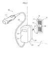
- FIG. 2 is an exemplary view illustrating an outer connection portion between a main body and one probe of the exemplary ultrasound diagnostic apparatus of FIG. 1 .
- FIGS. 3 and 4 illustrate views of an inner connection portion between the main body and the probe of the exemplary ultrasound diagnostic apparatus of FIG. 1 .
- the ultrasound diagnostic apparatus includes a main body 100, probes 200, a coupling assembly 300, and a controller 400.
- the main body 100 includes a body part 110, a display part 120 to display a result of an ultrasound of an object being examined, e.g., as part of a diagnostic procedure being performed.
- the main body 100 further includes a manipulation part 130 provided with manipulation buttons to operate the probes 200 as well as the display part 120 and other component parts of the ultrasound diagnostic apparatus.
- the main body 100 may further include a control unit (not shown) arranged within the body part 110 so as to control the probes 200, the display part 120, and other components based on a manipulation result of the manipulation part 130.
- a socket part 140 is arranged within the body part 110 so as to mechanically and electrically connect each probe 200 to the main body 100.
- the above-described control unit of the main body 100 converts signals received from the probes 200 into analog/digital receive signals. This may include, for example, properly executing time delays of the converted receive signals and summing the time delayed receive signals. This enables the output of digital receive-focused beams, which are signals exhibiting energy levels, which are reflected from focused points on respective transmit scan lines.
- the control unit filters out a noise ingredient in each digital receive-focused beam, and may also perform envelope detection processing in order to detect the intensity of a receive signal based on the filtered digital receive-focused beam, thereby producing digital ultrasound image data. Subsequently, the control unit performs scan conversion to convert a scan line of the digital ultrasound image data so that the digital ultrasound image data may be displayed on a display region of the display part 120.
- the control unit may perform additional image processing including, for example and without limitation, B-mode image processing, Doppler image processing, or the like, of the scan-converted digital ultrasound image data in order for it to be displayed as an ultrasound image on the display part 120 and as desired by a user.
- control unit executes red-green-blue (RGB) image processing of the image-processed digital ultrasound image, and transmits the RGB-processed digital ultrasound image data to the display part 120 so that the digital ultrasound image data may be displayed in the form of an ultrasound image on the display part 120.
- RGB red-green-blue
- the manipulation part 130 may be used by a user to input a diagnostic date, information of an object to be examined, and the like.
- the manipulation part 130 also may be used to select a particular region of the ultrasound image to be displayed on the display part 120.
- the main body 100 further includes a storage part (not shown), which compresses the digital ultrasound image data using, for example, a predetermined compression technique and stores the compressed digital ultrasound image data in association with other relevant information including, but not limited to, the diagnostic date, information pertaining to the object being examined, and the any other information provided by the user and received as input through the manipulation part 130.
- a storage part not shown
- the storage part may store all of the digital ultrasound image data for an object.
- the storage may include only a portion of the digital ultrasound image data corresponding to a partial region of the object being examined, for example, as selected by a user using the manipulation part 130 from the ultrasound image displayed on the display part 120.
- the socket part 140 includes a socket 142 having socket grooves 141 into which connection pins of a connector 230 of the associated probe 200 are inserted during connection of the connector 230 of the probe 200, a seating groove 143 formed at an outer peripheral surface of the socket 142, to seat the connector 230 of the probe 200, and an insertion hole 144 formed at a predetermined region of the socket 142, to insert a shaft 233 of the connector 230 of the probe 200.
- the socket 142 further includes socket pins (not shown), to which the respective connection pins of the connector 230 inserted into the socket grooves 141 are connected.
- the socket pins electrically connect the connector 230 to the control unit (not shown) of the main body 100 (shown in FIG. 1 ), thereby allowing a signal of the associated probe 200 to be transmitted to the control unit.
- the main body 100 may control various components of the probe 200, thereby activating the probe 200.
- the main body 100 may process or display various information acquired by the probe 200.
- One or more socket parts 140 may be provided, and the probes 200 having characteristics that vary from one another may be selectively connected thereto the plurality of socket parts 140.
- Each probe 200 may be a separate component of the ultrasound diagnostic apparatus to directly execute an ultrasound diagnostic procedure for a portion of an object to be examined.
- the probe 200 is connected to the main body 100 and may execute ultrasound diagnostics based on a command transmitted from the main body 100.
- the probe 200 may then transmit a diagnostic ultrasound signal to the main body 100.
- Such a probe 200 may be formed in various shapes and have an intrinsic characteristic. Each of the plurality of probes 200 may have intrinsic characteristics that vary from one another. Therefore, the probes 200 may be selectively connected to the main body 100 depending on the particular type and purpose of an examination to be conducted.
- each probe 200 includes a probing part 210 having a plurality of ultrasound elements, for example, arranged in an array formation.
- the probing part 210 is used to directly perform ultrasound diagnosis of an object to be examined using the ultrasound elements.
- Each probe 200 includes a cable 220 connected at one side thereof to the probing part 210 and a connector 230, which is connected to the other side of the cable 220.
- the connector 230 has connection pins corresponding in number to the number of the ultrasound elements.
- the probing part 210 of each probe 200 includes a one-dimensional, two-dimensional, or three-dimensional transducer (not shown).
- the probing parts 210 of the respective probes 200 transmit ultrasound beams, including pulse signals that are properly delayed and produced by the respective transducers, to an object to be examined along transmit scan lines.
- the probing parts 210 also convert the ultrasound signals (or ultrasound echo signals) reflected from the object into electrical signals, each signal having a different time of receipt with respect to the respective transducers.
- the converted electrical signals are transmitted from the probes 200 to the main body 100.
- each probe 200 is electrically connected to the probing part 210 through the cable 220, and thus an electrical signal of the probing part 210 is transmitted to the connector 230 through the cable 220.
- the electrical signal is transmitted to the control unit of the main body 100.
- the connector 230 includes, for example and without limitation, a housing 231, a seating member 232 formed to protrude from a flange portion of one surface of the housing 231, a shaft 233 formed to protrude outwardly from an inner portion of the housing 231 so as to mechanically connect the connector 230 to the socket part 140 of the main body 100, and a locking member 234 configured to maintain an electrical connection between the connector 230 and the socket part 140 as well as to mechanically lock the connector 230.
- the seating member 232 of the connector 230 may be, for example, a ferromagnetic substance made of a metal capable of being magnetized in a magnetic field.
- a metal may have, for example, strong magnetic properties and may include, but is not limited to, iron (Fe), nickel (Ni), or cobalt (Co), or an alloy thereof.
- the shaft 233 has a polygonal shape or an oval shape in section so as to be stably locked into a coupling member 310, as illustrated in the example of FIG. 3 .
- the connector 230 further includes at least one printed circuit board (PCB) 235 to enable a control signal and a diagnostic signal to be exchanged between the main body 100 and the associated probe 200.
- the control signal of the main body 100 is also used to drive the probe(s) 200 and connection pins 236 electrically connected to at least one PCB 235.
- the connection pins 236 are repositioned depending on the rotation of the shaft 233 so as to electrically connect the probe 200 to the main body 100.
- a terminal 237 includes a plurality of connection pins 236, which are inserted into the socket 142 of the socket part 140.
- the connector 230 also includes an input part 238 configured to receive input, including commands, from a user.
- the input part 238 may include hardware buttons or the like for user control, which are electrically connected to at least one PCB 235. For example, when a user presses a button of the input part 238, a signal is generated by the input part 238 and transmitted to the PCB 235 electrically connected to the input part 238.
- the PCB 235 electrically connected to the input part 238 transmits the signal of the input part 238 to the main body 100 through any one of the connection pins 236.
- the connector 230 is mechanically and electrically separated from the main body 100.
- the input part 238 may be arranged at the main body 100.
- the socket part 140 of the main body 100 should be mechanically and electrically coupled to the connector 230 of the probe 200 so as to allow coupling to each other to be secure and easy.
- the ultrasound diagnostic apparatus further includes a coupling assembly 300 and a controller 400.
- the coupling assembly 300 and the controller 400 may be provided within the body part 110 of the main body 100 or within the housing 231 of the connector 230 of the probe 200. In the example illustrated in FIG. 3 , the coupling assembly 300 and the controller 400 are arranged within the body part 110 of the main body 100.
- the coupling assembly 300 includes a coupling member 310 coupled to an end of the shaft 233 of the connector 230 of the associated probe 200 and rotated by interlocking with the shaft 233 while being disposed at a position extending from the insertion hole 144 of the socket part 140, a motor 320 to apply rotation force to the coupling member 310 so as to drive the shaft 233, a locking groove 330 to seat the locking member 234 of the shaft 233, and a detection part 340 to detect contact between the socket part 140 and the connector 230.
- the coupling member 310 further includes a coupling groove 311 to which the end of the shaft 233 is inserted.
- the coupling groove 311 has a shape that matches the sectional shape of the shaft 233, and the locking groove 330 serves to lock the connector 230 into the main body 100 during seating of the locking member 234.
- connection pins 236 may be possible to prevent the inserted probe 200 from being disconnected from the main body 100, for example, when the probe 200 is pulled excessively while a user diagnoses an object using the probe 200. Furthermore, it may also be possible to prevent the connection pins 236 from being bent due to the application of excessive force to the connector 230.
- the detection part 340 is located within the seating groove 143.
- the detection part 340 detects contact between the seating member 232 and the seating groove 143.
- the detection part 340 may also be located at a flange portion of the seating groove 143 of the body part 110. In this case, when the housing 231 of the connector 230 comes into contact with the body part 110 as the seating member 232 of the connector 230 is inserted into the seating groove 143, the detection part 340 may detect contact between the housing 231 and the body part 110.
- Such a detection part 340 includes at least one infrared detection part to transmit infrared light and to detect the transmitted infrared light.
- the detection part 340 may further include, for example and without limitation, a radio frequency (RF) detection part to transmit radio frequencies and to detect the transmitted radio frequencies, an ultrasound detection part to generate ultrasound waves and to detect the reflected ultrasound waves, a noncontact detection part such as a capacitance detection part to detect capacitance or the like, a pressure detection part to detect pressure corresponding to contact of the connector 230, and a contact detection part such as a switch part turning ON during contact of the connector or the like.
- RF radio frequency
- each of the infrared detection part, the RF detection part, and the ultrasound detection part include a part for transmitting RF signals and a part for receiving such signals.
- the RF transmitter part and RF receiver part may be arranged at upper and lower portions or left and right portions of the socket part 140, respectively.
- the controller 400 is electrically connected to the motor 320.
- the controller 400 transmits a drive control signal to the motor 320 so as to execute automatic locking between the main body 100 and the connector 230 when contact between the main body 100 and the connector 230 is detected through the detection part 340.
- the controller 400 transmits a drive control signal to the motor 320 so as to automatically release locking between the main body 100 and the connector 230 when the signal is transmitted from the input part 238.
- locking between the main body 100 and the connector 230 refers to a case in which the locking member 234 of the shaft 233 is seated at the locking groove 330 of the coupling assembly 300 by appropriately rotating the shaft 233.
- the connector 230 may be mechanically fixed to the main body 100 while the connection pins 236 of the connector 230 simultaneously come into contact with the socket pins of the socket part 140.
- the connector 230 is both mechanically and electrically connected to the main body 100.
- the ultrasound diagnostic apparatus in the illustrated embodiment further includes a fixing member capable of enhancing connection force between the connector 230 of the associated probe 200 and the socket part 140 of the main body 100.
- the fixing member may be provided in the main body 100 or the connector 230 of the probe 200.
- the fixing member may be arranged at the main body 100, the ultrasound diagnostic apparatus and techniques described herein are not intended to be limited thereto.
- the fixing member includes an electromagnet 510 to generate electromagnetic force using applied current.
- current is applied to the electromagnet 510 to generate electromagnetic force when the connector 230 is coupled to the main body 100, whereas the current is blocked from the electromagnet 510 so as to remove the electromagnetic force when the connector 230 is mechanically separated from the main body 100.
- the controller 400 allows current to be applied to the electromagnet 510, whereas when a command is input via the input part 238, the controller 400 blocks the current from being applied to the electromagnet 510.
- the controller 400 may be configured to block the electromagnet 510 only for a predetermined period of time, for example, in accordance with a command input via the input part 238.
- the predetermined time period may start, for example, when the command is input by the user or received by the input part 238.
- the electromagnet 510 may be arranged at a position to seat the seating member 232, which may be made of a magnetic substance.
- the electromagnet 510 is arranged at an end of the seating groove 143 of the socket part 140 while being arranged at a position facing an end of the seating member 232, as shown in FIG. 5 .
- the electromagnet 510 pulls the seating member 232, which may be a magnetic substance, by electromagnetic force generated due to application of current, such that the connector 230 is mechanically fixed to the main body 100.
- the electromagnet 510 may be arranged throughout or at a portion of the end of the seating groove 143 in the socket part 140.
- the electromagnet 510 may be arranged at an entrance of the seating groove 143 of the socket part 140 while being arranged at a position facing a side surface of the seating member 232, as shown in FIG. 6 .
- the electromagnet 510 pulls the seating member 232, which is the magnetic substance, by electromagnetic force generated due to application of current, such that the connector 230 is mechanically fixed to the main body 100.
- the electromagnet 510 may be arranged throughout or at a portion of the entrance of the seating groove 143 in the socket part 140.
- the fixing member and the detection part 340 may be arranged at different positions with respect to the seating groove 143.
- the fixing member and the detection part 340 may also be arranged at the same position.
- the fixing member further includes a current supply part (not shown) to apply current to the electromagnet 510.
- connection pins 236 When the connection pins 236 are inserted into the socket grooves 141, the seating member 232, which is the magnetic substance, is strongly and mechanically connected to the electromagnet 510 by attraction force (electromagnetic force) generated due to the application of a current to the electromagnet 510. Consequently, the electromagnetic force connecting the connector 230 and the socket part 140 may be further enhanced.
- attraction force electromagnet 510
- the fixing member alternatively includes a movable hook 520, a movement part 521 to move the hook 520, and a fixing groove 239 at which the hook 520 is seated.
- the hook 520 and the movement part 521 which are the fixing member, are arranged at the socket part 140, whereas the fixing groove 239 is arranged at the connector 230.
- the movement part 521 pulls the hook 520 based on a control command of the controller 400, thereby mechanically separating the connector 230.
- the controller 400 controls the movement part 521, for example, to pull the hook 520 for a predetermined time from when the command is input.
- the fixing groove 239 is formed at the side surface of the seating member 232, whereas the hook 520 is arranged at the entrance of the seating groove 143 of the socket part 140 while being arranged at a position facing the fixing groove 239 of the seating member 232.
- the hook 520 is pushed inward with respect to the socket part 140 when the seating member 232 slides into the seating groove 143.
- the hook 520 is located at the fixing groove 239 formed at the seating member 232, such that the connector 230 is mechanically fixed to the main body 100.
- the fixing groove 239 is arranged at the housing 231 of the connector 230 while positioned to be in contact with the body part 110 of the main body 100, whereas the hook 520 is arranged in the vicinity of the seating groove 143 of the socket part 140 in the body part 110 while being arranged at a position facing the fixing groove 239 of the seating member 232, as shown in FIG. 8 .
- the hook 520 is pushed by a predetermined distance depending on, for example, the distance to an end of the housing 231.
- the hook 520 is located at the fixing groove 239 formed at the housing 231, such that the connector 230 is mechanically fixed to the main body 100.
- At least one hook 520, movement part 521, and fixing groove 239 may be provided.
- the connector 230 When the seating member 232 is seated at the seating groove 143, the connector 230 is mechanically fixed to the main body 100 by the hook 520 and the fixing groove 239. Consequently, the connection force between the connector 230 and the socket part 140 may be further enhanced.
- FIG. 9 is an exemplary process flowchart for controlling the ultrasound diagnostic apparatus described herein.
- the process flowchart of FIG. 9 will be described with reference to the exemplary ultrasound diagnostic apparatuses of FIGS. 1 to 3 , as described above, but is not intended to be limited thereto.
- a rotation direction for locking will be referred to as "normal rotation” and a rotation direction for releasing the lock will be referred to as "reverse rotation.”
- the ultrasound diagnostic apparatus detects contact between the connector 230 and the main body 100 through the detection part 340 (at step 601), and the motor 320 is rotated in a normal direction when contact between the connector 230 and the main body 100 is detected (at step 602).
- the coupling member 310 is rotated by rotation of the motor 320, and the shaft 233 of the connector 230 coupled to the coupling member 310 is rotated by the rotation of the coupling member 310.
- the connector 230 is primarily and mechanically fixed to the main body 100 through the fixing member 510 or 520.
- the ultrasound diagnostic apparatus applies current to the electromagnet 510.
- the ultrasound diagnostic apparatus determines whether or not locking between the connector 230 and the main body 100 is completed during normal rotation of the motor 320 (at step 603).
- the determining whether or not locking is completed includes determining whether or not the number of normal rotations of the motor 320 is the predetermined number of rotations or more during the normal rotation of the motor 320. Furthermore, the determining whether or not locking is completed includes determining whether or not a normal rotation time of the motor 320 is the predetermined time, or whether or not current of the motor 320 is the predetermined current or more.
- the locking is completed when the locking member 234 formed at the shaft 233 is seated at the locking groove 330 in the main body 100.
- the connector 230 is secondarily and mechanically connected to main body 100 by such locking, and the connection pins 236 of the connector 230 come into contact with the socket pins of the socket 142, such that the connector 230 is electrically fixed to the main body 100.
- the ultrasound diagnostic apparatus stops the motor 320 (at step 604).
- the ultrasound diagnostic apparatus determines whether or not a command is input via the input part 238 (at step 605).
- the signal generated upon pressing the input part 238 is transmitted to the controller 400 through any one of the connection pins 236.
- the ultrasound diagnostic apparatus rotates the motor 320 in a reverse direction (at step 606).
- the coupling member 310 is rotated in reverse by the reverse rotation of the motor 320, the shaft 233 coupled to the coupling member 310 is rotated in reverse by the reverse rotation of the coupling member 310, and the locking member 234 is separated from the locking grove 330 by the reverse rotation of the shaft 233.
- the ultrasound diagnostic apparatus controls the fixing member 510 or 520 so that the connector 230 is primarily and mechanically separated from the main body 100.
- the ultrasound diagnostic apparatus blocks the current applied to the electromagnet 510, whereas when the fixing member is the hook 520, the ultrasound diagnostic apparatus controls the movement part 521 to move the hook 520.
- the ultrasound diagnostic apparatus determines whether or not locking release between the connector 230 and the main body 100 is completed (at step 607).
- the determining whether or not locking release is completed includes determining whether or not the number of reverse rotations of the motor 320 is the predetermined number of rotations or whether or not a reverse rotation time of the motor 320 is the predetermined time.
- the ultrasound diagnostic apparatus stops the motor 320 (at step 608).
- the connector 230 of the associated probe 200 may be mechanically and electrically coupled to the main body 100 with ease using the motor 320.
- FIG. 10 illustrates a view of an example ultrasound diagnostic apparatus.
- the ultrasound diagnostic apparatus includes a main body 100, probes 200, a coupling assembly 300, and a controller 400.
- a connector 230 of each probe 200 is not provided with the input part of the above embodiment.
- the coupling assembly 300 includes a coupling member 310 coupled to the end of the shaft 233 of the connector 230 of the associated probe 200 and rotated by interlocking with the shaft 233 while being arranged at the position extending from the insertion hole 144 of the socket part 140, a motor 320 to apply rotation force to the coupling member 310 so as to drive the shaft 233, a locking groove 330 to seat the locking member 234 of the shaft 233, and an input part 350 used to input a command by a user while being arranged at the body part 110.
- the coupling member 310 further includes a coupling groove 311 to which the end of the shaft 233 is inserted and coupled.
- the coupling groove 311 has a shape equal to the sectional shape of the shaft 233, and the locking groove 330 serves to lock the connector 230 into the main body 100 during seating of the locking member 234.
- the input part 350 is constituted of buttons, etc. When the input part 350 is pressed by a user, a signal generated upon pressing the input part 350 is transmitted to the PCB 235 electrically connected to the input part 350.
- the controller 400 is electrically connected to the motor 320.
- the controller 400 transmits a drive control signal to the motor 320 so as to execute automatic locking between the main body 100 and the connector 230 based on a command input by a user via the input part 350.
- the controller 400 transmits a drive control signal to the motor 320 so as to automatically release locking between the main body 100 and the connector 230 when the command signal is again input via the input part 350.
- locking between the main body 100 and the connector 230 refers to a case in which the locking member 234 of the shaft 233 is seated at the locking groove 330 of the coupling assembly 300 by rotation of the shaft 233.
- the connector 230 is mechanically fixed to the main body 100 and simultaneously the connection pins 236 of the connector 230 come into contact with the socket pins of the socket part 140.
- the connector 230 is electrically connected to the main body 100.
- the ultrasound diagnostic apparatus in the example illustrated in FIG. 10 further includes a fixing member such as that shown in FIGS. 5 to 8 and as described above.
- the controller 400 is electrically connected to the fixing member 510.
- the controller 400 controls the fixing member 510 so that the connector 230 is mechanically connected to the main body 100.
- the controller 400 controls the fixing member 510 so that the connector 230 is mechanically separated from the main body 100.
- the controller 400 transmits a drive control signal to the motor 320 so as to automatically release locking between the main body 100 and the connector 230.
- the ultrasound diagnostic apparatus applies current to the electromagnet for locking and blocks the current applied to the electromagnet for releasing the lock.
- the ultrasound diagnostic apparatus moves the hook during the locking release.
- FIGS. 11 and 12 are exemplary views illustrating another example of an ultrasound diagnostic apparatus.
- FIG. 11 is an exemplary view illustrating the ultrasound diagnostic apparatus including an electromagnet as a fixing member.
- FIG. 12 is an exemplary view illustrating the ultrasound diagnostic apparatus including a hook as the fixing member.
- the ultrasound diagnostic apparatus includes a main body 100, probes 200, a coupling assembly 300, a controller 400, and a fixing member 510 or 520. Since configurations of the main body 100 and the probes 200 are similar to those of the examples described above, no additional description will be provided for this example.
- the coupling assembly 300 includes a coupling member 310 coupled to the end of the shaft 233 of the connector 230 of the associated probe 200 and rotated by interlocking with the shaft 233 while being arranged at a position extending from the insertion hole 144 of the socket part 140, a motor 320 to apply rotation force to the coupling member 310 so as to drive the shaft 233, and a locking groove 330 to seat the locking member 234 of the shaft 233.
- the fixing member includes an electromagnet 510 to generate electromagnetic force using current, and a magnetic field detection part 511 to detect a magnetic field of the electromagnet 510.
- the electromagnet 510 may be installed, for example, in the vicinity of the seating groove 143.
- the controller 400 continuously applies current to the electromagnet 510, and controls rotation of the motor 320 in the normal direction to lock the connector 230 into the main body 100 when a change in the magnetic field is detected by the magnetic field detection part 511.
- the controller 400 blocks the current applied to the electromagnet 510 for a predetermined time to mechanically separate the connector 230 from the main body 100, and controls rotation of the motor 320 in the reverse direction to automatically release the lock between the connector 230 and the main body 100.
- the main body 100 may be locked to the connector 230 when, for example, the locking member 234 of the shaft 233 is seated at the locking groove 330 of the coupling assembly 300 when the shaft 233 is rotated in an appropriate direction.
- the connector 230 is mechanically fixed to the main body 100 and the connection pins 236 of the connector 230 simultaneously come into contact with the socket pins of the socket part 140.
- the connector 230 is electrically and mechanically connected to the main body 100.
- the fixing member further includes a current supply part (not shown) to apply current to the electromagnet 510.
- the seating member 232 which is the magnetic substance, is strongly and mechanically connected to the electromagnet 510 by attraction force (electromagnetic force) generated due to application of current to the electromagnet 510. Consequently, the electromagnet force connecting the connector 230 and the socket part 140 may be further enhanced. Furthermore, the motor 320 may be controlled based on the change in the magnetic field generated by the electromagnet 510, thereby automatically performing locking between the connector 230 and the main body 100.
- the coupling assembly 300 includes a coupling member 310 coupled to the end of the shaft 233 of the connector 230 of the associated probe 200.
- the coupling member 310 may be rotated by interlocking with the shaft 233 while being arranged at the position extending from the insertion hole 144 of the socket part 140.
- the coupling assembly 300 also includes a motor 320 to apply rotation force to the coupling member 310 so as to drive the shaft 233 and a locking groove 330 to seat the locking member 234 of the shaft 233.
- the fixing member includes a movable hook 520, a movement part 521 to automatically move the hook 520, and a position detection part 522 to detect position change of the hook 520.
- the hook 520 is moved toward the body part 110 by elasticity generated when the seating member 232 of the connector 230 is slid into the seating groove 143 of the socket part 140. Subsequently, when the hook 520 is located at the fixing groove 239, the hook 520 is seated in the fixing groove 239, and thus the connector 230 is mechanically connected to the main body 100.
- the position detection part 522 detects a position of the hook 520 and transmits the detected position to the controller 400.
- the controller 400 controls rotation of the motor 320 in the normal direction to lock the connector 230 into the main body 100.
- the controller 400 controls driving of the movement part 521 for a predetermined time to mechanically separate the connector 230 from the main body 100, moves the hook 520 toward the body part 110, and controls rotation of the motor 320 in the reverse direction to automatically release locking between the connector 230 and the main body 100.
- locking between the main body 100 and the connector 230 refers to a case in which the locking member 234 of the shaft 233 becomes seated at the locking groove 330 of the coupling assembly 300 through proper rotation of the shaft 233.
- the connector 230 is mechanically fixed to the main body 100 and simultaneously the connection pins 236 of the connector 230 come into contact with the socket pins of the socket part 140.
- the connector 230 is electrically and mechanically connected to the main body 100.
- At least one hook 520, movement part 521, and fixing groove 239 may be provided.
- the seating member 232 which is the magnetic substance, is strongly and mechanically connected to the electromagnet 510 by attraction force (electromagnetic force) generated due to application of current to the electromagnet 510. Consequently, connection force between the connector 230 and the socket part 140 may be further enhanced. Furthermore, driving of the motor 320 is controlled based on the magnetic field change of the electromagnet 510, thereby automatically performing locking between the connector 230 and the main body 100.
- FIGS. 13 and 14 are views illustrating yet another exemplary ultrasound diagnostic apparatus according to yet another exemplary embodiment. Components similar to the above illustrated embodiment will be described in brief.
- the ultrasound diagnostic apparatus includes a main body 100 and probes 200.
- the main body 100 includes a body part 110, a display part 120, a manipulation part 130, a control unit (not shown), and a socket part 140.
- the socket part 140 includes a socket 142 having socket grooves 141 into which connection pins of a connector 230 of each probe 200 are inserted during connection of the connector 230 of the probe 200, a seating groove 143 formed at an outer peripheral surface of the socket 142, to seat the connector 230 of the probe 200, and an insertion hole 144 into which a shaft 360 is inserted while being formed at a predetermined region of the socket 142.
- a probing part 210 of the probe 200 is electrically connected to various components of the main body 100.
- the main body 100 may control various components of the probe 200, thereby activating the probe 200.
- the main body 100 may process or display various information acquired by the probe 200.
- a plurality of socket parts 140 may be provided, and the probes 200 having characteristics different from one another may be selectively connected to the plural socket parts 140.
- Each probe 200 refers to a component to directly execute ultrasound diagnosis upon an examination portion of an object to be examined.
- the probe 200 is connected to the main body 100 executes ultrasound diagnosis based on a command transmitted from the main body 100, and transmits the diagnosed ultrasound signal to the main body 100.
- Each probe 200 includes a probing part 210, a cable 220, and a connector 230.
- the connector 230 includes a housing 231, a seating member 232 formed to protrude from a flange portion of one surface of the housing 231, and a shaft hole 240 recessed inward of the housing 231.
- the shaft hole 240 has a polygonal shape or an oval shape in section so as to be stably locked into a shaft 360.
- the connector 230 further includes at least one printed circuit board (PCB) 235, connection pins 236 moved depending on rotation of the shaft 360 so as to electrically connect the associated probe 200 to the main body 100, a terminal 237, and an input part 238 used to input a command by a user.
- PCB printed circuit board
- the PCB 235 electrically connected to the input part 238 transmits the signal of the input part 238 to the main body 100 through any one of the connection pins 236.
- the connector 230 is mechanically and electrically separated from the main body 100.
- the socket part 140 of the main body 100 should be mechanically and electrically coupled to the connector 230 of the probe 200 so as to allow coupling to each other to be secure and easy.
- the ultrasound diagnostic apparatus further includes, but is not limited to, a coupling assembly 300 and a controller 400.
- the coupling assembly 300 and the controller 400 may be provided within the body part 110 of the main body 100 or alternatively, within the housing 231 of the connector 230 of the associated probe 200.
- the coupling assembly 300 and the controller 400 will be described as being arranged within the body part 110 of the main body 100.
- the ultrasound diagnostic apparatus and techniques described herein are not intended to be limited thereto.
- the coupling assembly 300 includes a shaft 360 inserted into the shaft hole 240 of the connector 230, a motor 320 to apply rotation force to the shaft 360 so as to drive the shaft 360, a protrusion member 321 connected to the motor 320 so as to apply rotational force to the shaft 360 while outwardly protruding the shaft 360 during contact of the connector 230, and a detection part 340 to detect contact between the socket part 140 and the connector 230.
- the shaft 360 when contact between the socket part 140 and the connector 230 is detected, the shaft 360 outwardly protrudes through the insertion hole 144 of the socket part 140, whereas when a command is input via the input part 238 by a user, the shaft 360 is retracted into the insertion hole 144 of the socket part 140.
- the detection part 340 may be located within the seating groove 143.
- the detection part 340 detects contact between the seating member 232 and the seating groove 143.
- the controller 400 is electrically connected to the motor 320.
- the controller 400 controls the driving of the protrusion member 321 so that the shaft 360 protrudes outwards. Consequently, the protruding shaft 360 is inserted into the shaft hole 240 of the connector 230.
- the controller 400 transmits a drive control signal to the motor 320 so as to electrically connect the connector 230 to the main body 100, thereby rotating the shaft 360.
- the controller 400 transmits a drive control signal to the motor 320 when a signal is transmitted from the input part 238, thereby retracting the shaft 360. Consequently, the electrical connection between the main body 100 and the connector 230 is released.
- the ultrasound diagnostic apparatus in this example further includes a fixing member capable of enhancing connection force between the connector 230 of the associated probe 200 and the socket part 140 of the main body 100.
- the fixing member may be provided in at least one of the main body 100 and the connector 230 of the probe 200.
- the fixing member arranged at the main body 100 may be implemented in a variety of ways according to the exemplary configurations of the ultrasound diagnostic apparatus described herein or as desired for a particular implementation.
- a connector of the probe may have a simplified interior structure and the probe may have an improved design.
- a shaft rotated by a locking handle does not pass through a printed circuit board within a connector, thereby enabling easy manufacture of the printed circuit board, and X-talk characteristics may be improved by insuring an interior space of the connector.
Applications Claiming Priority (1)
| Application Number | Priority Date | Filing Date | Title |
|---|---|---|---|
| KR1020110142451A KR20130074398A (ko) | 2011-12-26 | 2011-12-26 | 초음파 진단 장치 및 그 제어 방법 |
Publications (1)
| Publication Number | Publication Date |
|---|---|
| EP2609867A1 true EP2609867A1 (fr) | 2013-07-03 |
Family
ID=47665839
Family Applications (1)
| Application Number | Title | Priority Date | Filing Date |
|---|---|---|---|
| EP12199483.4A Withdrawn EP2609867A1 (fr) | 2011-12-26 | 2012-12-27 | Appareil de diagnostic ultrasonique et son procédé de contrôle |
Country Status (4)
| Country | Link |
|---|---|
| US (1) | US20130165790A1 (fr) |
| EP (1) | EP2609867A1 (fr) |
| JP (1) | JP2013132560A (fr) |
| KR (1) | KR20130074398A (fr) |
Cited By (2)
| Publication number | Priority date | Publication date | Assignee | Title |
|---|---|---|---|---|
| EP3056152A1 (fr) * | 2015-02-13 | 2016-08-17 | Samsung Medison Co., Ltd. | Appareil d'imagerie à ultrasons et procédé de commande correspondant |
| WO2021186509A1 (fr) * | 2020-03-16 | 2021-09-23 | オリンパス株式会社 | Système d'endoscope |
Families Citing this family (11)
| Publication number | Priority date | Publication date | Assignee | Title |
|---|---|---|---|---|
| US10667790B2 (en) | 2012-03-26 | 2020-06-02 | Teratech Corporation | Tablet ultrasound system |
| US9877699B2 (en) | 2012-03-26 | 2018-01-30 | Teratech Corporation | Tablet ultrasound system |
| CN103908291A (zh) * | 2012-12-28 | 2014-07-09 | Ge医疗系统环球技术有限公司 | 一种超声探头切换装置及相应的超声成像系统 |
| KR102445161B1 (ko) * | 2015-01-20 | 2022-09-21 | 삼성메디슨 주식회사 | 프로브, 초음파 영상 장치 및 초음파 영상 장치의 제어 방법 |
| US20170000456A1 (en) * | 2015-07-01 | 2017-01-05 | Edan Instruments, Inc. | Apparatus and method for semi-automatic ultrasound transducer connector lock |
| CN105997143A (zh) * | 2016-06-13 | 2016-10-12 | 杭州融超科技有限公司 | 一种超声探头自动装卸装置及其操作方法 |
| KR101692415B1 (ko) * | 2016-07-08 | 2017-01-03 | 에이치앤케이엔지니어링(주) | 초음파를 이용한 케이블 및 강연선 부식 및 단선 비파괴 검사장치 |
| USD825763S1 (en) * | 2016-11-22 | 2018-08-14 | Samsung Medison Co., Ltd. | Ultrasound diagnostic unit |
| USD809142S1 (en) * | 2016-11-22 | 2018-01-30 | Samsung Medison Co., Ltd. | Monitor arm for ultrasound diagnostic units |
| KR102384028B1 (ko) * | 2016-12-19 | 2022-04-07 | 지멘스 메디컬 솔루션즈 유에스에이, 인크. | 프로브 인터페이스 장치 및 이를 구비하는 초음파 진단 장치 |
| CN114052775A (zh) * | 2020-07-29 | 2022-02-18 | 深圳迈瑞生物医疗电子股份有限公司 | 超声成像设备的供电装置、超声成像系统、超声成像设备 |
Citations (4)
| Publication number | Priority date | Publication date | Assignee | Title |
|---|---|---|---|---|
| US5542425A (en) * | 1994-12-20 | 1996-08-06 | Acuson Corporation | Apparatus and method for preventing contact damage in electrical equipment |
| US5882310A (en) * | 1997-12-01 | 1999-03-16 | Acuson Corporation | Ultrasound transducer connector and multiport imaging system receptacle arrangement |
| US20070135803A1 (en) * | 2005-09-14 | 2007-06-14 | Amir Belson | Methods and apparatus for performing transluminal and other procedures |
| JP2008086653A (ja) * | 2006-10-04 | 2008-04-17 | Aloka Co Ltd | 超音波診断装置 |
Family Cites Families (7)
| Publication number | Priority date | Publication date | Assignee | Title |
|---|---|---|---|---|
| US5174772A (en) * | 1992-01-22 | 1992-12-29 | The United States Of America As Represented By The Administrator Of The National Aeronautics & Space Administration | Work attachment mechanism/work attachment fixture |
| US5271286A (en) * | 1992-09-17 | 1993-12-21 | The United States Of America As Represented By The Administrator Of The National Aeronautics And Space Administration | Spline screw multiple rotations mechanism |
| US5344331A (en) * | 1993-01-15 | 1994-09-06 | Hubbell Incorporated | Electrical connector system, especially for electric vehicles |
| DE9414105U1 (de) * | 1994-08-31 | 1994-11-03 | Siemens Nixdorf Inf Syst | Vorrichtung zum Einrücken einer Steckbaugruppe in einen Baugruppenträger |
| US6498730B2 (en) * | 2000-12-13 | 2002-12-24 | International Business Machines Corporation | Apparatus and method for inserting, retaining and extracting printed circuit boards |
| JP4602017B2 (ja) * | 2004-07-15 | 2010-12-22 | 株式会社東芝 | 超音波診断装置 |
| JP2009240342A (ja) * | 2008-03-28 | 2009-10-22 | Ge Medical Systems Global Technology Co Llc | 超音波診断装置 |
-
2011
- 2011-12-26 KR KR1020110142451A patent/KR20130074398A/ko not_active Application Discontinuation
-
2012
- 2012-12-21 JP JP2012279806A patent/JP2013132560A/ja active Pending
- 2012-12-26 US US13/727,456 patent/US20130165790A1/en not_active Abandoned
- 2012-12-27 EP EP12199483.4A patent/EP2609867A1/fr not_active Withdrawn
Patent Citations (4)
| Publication number | Priority date | Publication date | Assignee | Title |
|---|---|---|---|---|
| US5542425A (en) * | 1994-12-20 | 1996-08-06 | Acuson Corporation | Apparatus and method for preventing contact damage in electrical equipment |
| US5882310A (en) * | 1997-12-01 | 1999-03-16 | Acuson Corporation | Ultrasound transducer connector and multiport imaging system receptacle arrangement |
| US20070135803A1 (en) * | 2005-09-14 | 2007-06-14 | Amir Belson | Methods and apparatus for performing transluminal and other procedures |
| JP2008086653A (ja) * | 2006-10-04 | 2008-04-17 | Aloka Co Ltd | 超音波診断装置 |
Cited By (3)
| Publication number | Priority date | Publication date | Assignee | Title |
|---|---|---|---|---|
| EP3056152A1 (fr) * | 2015-02-13 | 2016-08-17 | Samsung Medison Co., Ltd. | Appareil d'imagerie à ultrasons et procédé de commande correspondant |
| US10094807B2 (en) | 2015-02-13 | 2018-10-09 | Samsung Medison Co., Ltd. | Ultrasound imaging apparatus and method of controlling the same |
| WO2021186509A1 (fr) * | 2020-03-16 | 2021-09-23 | オリンパス株式会社 | Système d'endoscope |
Also Published As
| Publication number | Publication date |
|---|---|
| KR20130074398A (ko) | 2013-07-04 |
| US20130165790A1 (en) | 2013-06-27 |
| JP2013132560A (ja) | 2013-07-08 |
Similar Documents
| Publication | Publication Date | Title |
|---|---|---|
| EP2609867A1 (fr) | Appareil de diagnostic ultrasonique et son procédé de contrôle | |
| JP4772540B2 (ja) | 超音波診断装置 | |
| CN108272469B (zh) | 一种双频率血管内超声成像探头 | |
| US9149249B2 (en) | Ultrasound image diagnosis apparatus and a control method for measuring diagnosis parameters | |
| US6269262B1 (en) | Biomagnetic field measuring apparatus | |
| US8961424B2 (en) | Ultrasound image diagnosis apparatus | |
| EP2127602A1 (fr) | Appareil de diagnostic à ultrasons | |
| CN105796127B (zh) | 探头组件、超声成像设备以及超声成像设备的控制方法 | |
| US20160238563A1 (en) | Ultrasound imaging apparatus and method of controlling the same | |
| KR20110065739A (ko) | 초음파 진단 장치 | |
| US5855558A (en) | Ultrasonic probe and ultrasonic diagnostic apparatus | |
| EP3829446B1 (fr) | Dispositifs, systèmes et procédés de détection de pouls pulmonaire en ultrason | |
| US11759176B2 (en) | Ultrasound image processing | |
| JP5179812B2 (ja) | 超音波診断装置、超音波画像処理装置、及び超音波画像処理プログラム | |
| CN112263273A (zh) | 超声波的高低频自由切换方法及其装置 | |
| JP4673074B2 (ja) | 超音波診断装置 | |
| US20210236083A1 (en) | Ultrasound imaging apparatus and control method thereof | |
| JP2010005322A (ja) | 超音波診断装置 | |
| KR100646714B1 (ko) | 프로브 자동로킹장치를 구비한 초음파 영상장치 | |
| JP4817315B2 (ja) | 超音波微細血管可視化方法及び装置 | |
| CN214157363U (zh) | 用于超声扫描的探头结构 | |
| JP2012223353A (ja) | 超音波診断装置 | |
| US20220125406A1 (en) | Ultrasound diagnostic apparatus and method for controlling ultrasound diagnostic apparatus | |
| JP2011024782A (ja) | 超音波診断装置及び血流速度計測用制御プログラム | |
| KR20110041122A (ko) | 초음파 진단 장치 |
Legal Events
| Date | Code | Title | Description |
|---|---|---|---|
| PUAI | Public reference made under article 153(3) epc to a published international application that has entered the european phase |
Free format text: ORIGINAL CODE: 0009012 |
|
| AK | Designated contracting states |
Kind code of ref document: A1 Designated state(s): AL AT BE BG CH CY CZ DE DK EE ES FI FR GB GR HR HU IE IS IT LI LT LU LV MC MK MT NL NO PL PT RO RS SE SI SK SM TR |
|
| AX | Request for extension of the european patent |
Extension state: BA ME |
|
| 17P | Request for examination filed |
Effective date: 20140103 |
|
| RBV | Designated contracting states (corrected) |
Designated state(s): AL AT BE BG CH CY CZ DE DK EE ES FI FR GB GR HR HU IE IS IT LI LT LU LV MC MK MT NL NO PL PT RO RS SE SI SK SM TR |
|
| 17Q | First examination report despatched |
Effective date: 20191106 |
|
| STAA | Information on the status of an ep patent application or granted ep patent |
Free format text: STATUS: THE APPLICATION IS DEEMED TO BE WITHDRAWN |
|
| 18D | Application deemed to be withdrawn |
Effective date: 20200603 |