EP2608751B1 - Reducing crimping damage to polymer scaffold - Google Patents
Reducing crimping damage to polymer scaffold Download PDFInfo
- Publication number
- EP2608751B1 EP2608751B1 EP11749667.9A EP11749667A EP2608751B1 EP 2608751 B1 EP2608751 B1 EP 2608751B1 EP 11749667 A EP11749667 A EP 11749667A EP 2608751 B1 EP2608751 B1 EP 2608751B1
- Authority
- EP
- European Patent Office
- Prior art keywords
- scaffold
- diameter
- balloon
- polymer
- crimping
- Prior art date
- Legal status (The legal status is an assumption and is not a legal conclusion. Google has not performed a legal analysis and makes no representation as to the accuracy of the status listed.)
- Not-in-force
Links
- 238000002788 crimping Methods 0.000 title claims description 149
- 229920000642 polymer Polymers 0.000 title claims description 138
- 238000000034 method Methods 0.000 claims description 65
- 230000002829 reductive effect Effects 0.000 claims description 39
- 238000000576 coating method Methods 0.000 claims description 33
- 239000011248 coating agent Substances 0.000 claims description 29
- 230000001788 irregular Effects 0.000 claims description 25
- 230000009467 reduction Effects 0.000 claims description 24
- 238000007373 indentation Methods 0.000 claims description 23
- 238000005452 bending Methods 0.000 claims description 20
- 239000002861 polymer material Substances 0.000 claims description 12
- JVTAAEKCZFNVCJ-REOHCLBHSA-N L-lactic acid Chemical group C[C@H](O)C(O)=O JVTAAEKCZFNVCJ-REOHCLBHSA-N 0.000 claims description 9
- 229920001432 poly(L-lactide) Polymers 0.000 claims description 6
- 230000009477 glass transition Effects 0.000 claims description 5
- 238000010438 heat treatment Methods 0.000 claims description 5
- 229920006254 polymer film Polymers 0.000 claims description 4
- 238000005520 cutting process Methods 0.000 claims description 3
- 238000010926 purge Methods 0.000 claims 1
- 239000002184 metal Substances 0.000 description 56
- 229910052751 metal Inorganic materials 0.000 description 56
- 230000008569 process Effects 0.000 description 35
- 239000000463 material Substances 0.000 description 22
- 238000004519 manufacturing process Methods 0.000 description 14
- 230000008859 change Effects 0.000 description 8
- 230000003068 static effect Effects 0.000 description 8
- 230000007246 mechanism Effects 0.000 description 7
- 230000000712 assembly Effects 0.000 description 6
- 238000000429 assembly Methods 0.000 description 6
- 230000000694 effects Effects 0.000 description 6
- 238000011068 loading method Methods 0.000 description 6
- 238000013459 approach Methods 0.000 description 5
- 230000007547 defect Effects 0.000 description 5
- 230000006872 improvement Effects 0.000 description 5
- 238000012986 modification Methods 0.000 description 5
- 230000004048 modification Effects 0.000 description 5
- 230000015572 biosynthetic process Effects 0.000 description 4
- 238000013461 design Methods 0.000 description 4
- 239000003814 drug Substances 0.000 description 4
- 230000003993 interaction Effects 0.000 description 4
- 230000014759 maintenance of location Effects 0.000 description 4
- 238000012545 processing Methods 0.000 description 4
- 230000000087 stabilizing effect Effects 0.000 description 4
- 230000009471 action Effects 0.000 description 3
- 230000009286 beneficial effect Effects 0.000 description 3
- 229940079593 drug Drugs 0.000 description 3
- 239000007769 metal material Substances 0.000 description 3
- 229920003023 plastic Polymers 0.000 description 3
- 239000004033 plastic Substances 0.000 description 3
- 229920001606 poly(lactic acid-co-glycolic acid) Polymers 0.000 description 3
- 230000005855 radiation Effects 0.000 description 3
- 238000012360 testing method Methods 0.000 description 3
- 230000002159 abnormal effect Effects 0.000 description 2
- 230000002411 adverse Effects 0.000 description 2
- 230000003247 decreasing effect Effects 0.000 description 2
- 238000006073 displacement reaction Methods 0.000 description 2
- 238000009413 insulation Methods 0.000 description 2
- 238000012423 maintenance Methods 0.000 description 2
- 230000001681 protective effect Effects 0.000 description 2
- 230000000452 restraining effect Effects 0.000 description 2
- 238000010200 validation analysis Methods 0.000 description 2
- 238000005299 abrasion Methods 0.000 description 1
- 238000009825 accumulation Methods 0.000 description 1
- 238000004458 analytical method Methods 0.000 description 1
- 238000002399 angioplasty Methods 0.000 description 1
- 230000004888 barrier function Effects 0.000 description 1
- 239000011324 bead Substances 0.000 description 1
- 239000011449 brick Substances 0.000 description 1
- 238000006243 chemical reaction Methods 0.000 description 1
- 150000001875 compounds Chemical class 0.000 description 1
- 230000006835 compression Effects 0.000 description 1
- 238000007906 compression Methods 0.000 description 1
- 238000011109 contamination Methods 0.000 description 1
- 238000013270 controlled release Methods 0.000 description 1
- 238000005336 cracking Methods 0.000 description 1
- 125000004122 cyclic group Chemical group 0.000 description 1
- 238000009826 distribution Methods 0.000 description 1
- 238000004836 empirical method Methods 0.000 description 1
- 230000002349 favourable effect Effects 0.000 description 1
- 230000001771 impaired effect Effects 0.000 description 1
- 238000003698 laser cutting Methods 0.000 description 1
- 239000003550 marker Substances 0.000 description 1
- 230000010534 mechanism of action Effects 0.000 description 1
- 239000012528 membrane Substances 0.000 description 1
- 238000001000 micrograph Methods 0.000 description 1
- 230000003278 mimic effect Effects 0.000 description 1
- 238000012544 monitoring process Methods 0.000 description 1
- 238000009740 moulding (composite fabrication) Methods 0.000 description 1
- 229920002635 polyurethane Polymers 0.000 description 1
- 239000004814 polyurethane Substances 0.000 description 1
- 238000002360 preparation method Methods 0.000 description 1
- 238000003825 pressing Methods 0.000 description 1
- 230000000717 retained effect Effects 0.000 description 1
- 230000001954 sterilising effect Effects 0.000 description 1
- 238000004659 sterilization and disinfection Methods 0.000 description 1
- 230000009897 systematic effect Effects 0.000 description 1
- 229940124597 therapeutic agent Drugs 0.000 description 1
- 238000012546 transfer Methods 0.000 description 1
Images


Classifications
-
- A—HUMAN NECESSITIES
- A61—MEDICAL OR VETERINARY SCIENCE; HYGIENE
- A61F—FILTERS IMPLANTABLE INTO BLOOD VESSELS; PROSTHESES; DEVICES PROVIDING PATENCY TO, OR PREVENTING COLLAPSING OF, TUBULAR STRUCTURES OF THE BODY, e.g. STENTS; ORTHOPAEDIC, NURSING OR CONTRACEPTIVE DEVICES; FOMENTATION; TREATMENT OR PROTECTION OF EYES OR EARS; BANDAGES, DRESSINGS OR ABSORBENT PADS; FIRST-AID KITS
- A61F2/00—Filters implantable into blood vessels; Prostheses, i.e. artificial substitutes or replacements for parts of the body; Appliances for connecting them with the body; Devices providing patency to, or preventing collapsing of, tubular structures of the body, e.g. stents
- A61F2/82—Devices providing patency to, or preventing collapsing of, tubular structures of the body, e.g. stents
-
- A—HUMAN NECESSITIES
- A61—MEDICAL OR VETERINARY SCIENCE; HYGIENE
- A61F—FILTERS IMPLANTABLE INTO BLOOD VESSELS; PROSTHESES; DEVICES PROVIDING PATENCY TO, OR PREVENTING COLLAPSING OF, TUBULAR STRUCTURES OF THE BODY, e.g. STENTS; ORTHOPAEDIC, NURSING OR CONTRACEPTIVE DEVICES; FOMENTATION; TREATMENT OR PROTECTION OF EYES OR EARS; BANDAGES, DRESSINGS OR ABSORBENT PADS; FIRST-AID KITS
- A61F2/00—Filters implantable into blood vessels; Prostheses, i.e. artificial substitutes or replacements for parts of the body; Appliances for connecting them with the body; Devices providing patency to, or preventing collapsing of, tubular structures of the body, e.g. stents
- A61F2/95—Instruments specially adapted for placement or removal of stents or stent-grafts
- A61F2/9522—Means for mounting a stent or stent-graft onto or into a placement instrument
- A61F2/9524—Iris-type crimpers
-
- B—PERFORMING OPERATIONS; TRANSPORTING
- B29—WORKING OF PLASTICS; WORKING OF SUBSTANCES IN A PLASTIC STATE IN GENERAL
- B29C—SHAPING OR JOINING OF PLASTICS; SHAPING OF MATERIAL IN A PLASTIC STATE, NOT OTHERWISE PROVIDED FOR; AFTER-TREATMENT OF THE SHAPED PRODUCTS, e.g. REPAIRING
- B29C53/00—Shaping by bending, folding, twisting, straightening or flattening; Apparatus therefor
- B29C53/22—Corrugating
- B29C53/30—Corrugating of tubes
-
- B—PERFORMING OPERATIONS; TRANSPORTING
- B29—WORKING OF PLASTICS; WORKING OF SUBSTANCES IN A PLASTIC STATE IN GENERAL
- B29C—SHAPING OR JOINING OF PLASTICS; SHAPING OF MATERIAL IN A PLASTIC STATE, NOT OTHERWISE PROVIDED FOR; AFTER-TREATMENT OF THE SHAPED PRODUCTS, e.g. REPAIRING
- B29C67/00—Shaping techniques not covered by groups B29C39/00 - B29C65/00, B29C70/00 or B29C73/00
- B29C67/0014—Shaping techniques not covered by groups B29C39/00 - B29C65/00, B29C70/00 or B29C73/00 for shaping tubes or blown tubular films
-
- B—PERFORMING OPERATIONS; TRANSPORTING
- B29—WORKING OF PLASTICS; WORKING OF SUBSTANCES IN A PLASTIC STATE IN GENERAL
- B29D—PRODUCING PARTICULAR ARTICLES FROM PLASTICS OR FROM SUBSTANCES IN A PLASTIC STATE
- B29D23/00—Producing tubular articles
-
- A—HUMAN NECESSITIES
- A61—MEDICAL OR VETERINARY SCIENCE; HYGIENE
- A61F—FILTERS IMPLANTABLE INTO BLOOD VESSELS; PROSTHESES; DEVICES PROVIDING PATENCY TO, OR PREVENTING COLLAPSING OF, TUBULAR STRUCTURES OF THE BODY, e.g. STENTS; ORTHOPAEDIC, NURSING OR CONTRACEPTIVE DEVICES; FOMENTATION; TREATMENT OR PROTECTION OF EYES OR EARS; BANDAGES, DRESSINGS OR ABSORBENT PADS; FIRST-AID KITS
- A61F2/00—Filters implantable into blood vessels; Prostheses, i.e. artificial substitutes or replacements for parts of the body; Appliances for connecting them with the body; Devices providing patency to, or preventing collapsing of, tubular structures of the body, e.g. stents
- A61F2/95—Instruments specially adapted for placement or removal of stents or stent-grafts
- A61F2/9522—Means for mounting a stent or stent-graft onto or into a placement instrument
-
- A—HUMAN NECESSITIES
- A61—MEDICAL OR VETERINARY SCIENCE; HYGIENE
- A61F—FILTERS IMPLANTABLE INTO BLOOD VESSELS; PROSTHESES; DEVICES PROVIDING PATENCY TO, OR PREVENTING COLLAPSING OF, TUBULAR STRUCTURES OF THE BODY, e.g. STENTS; ORTHOPAEDIC, NURSING OR CONTRACEPTIVE DEVICES; FOMENTATION; TREATMENT OR PROTECTION OF EYES OR EARS; BANDAGES, DRESSINGS OR ABSORBENT PADS; FIRST-AID KITS
- A61F2/00—Filters implantable into blood vessels; Prostheses, i.e. artificial substitutes or replacements for parts of the body; Appliances for connecting them with the body; Devices providing patency to, or preventing collapsing of, tubular structures of the body, e.g. stents
- A61F2/95—Instruments specially adapted for placement or removal of stents or stent-grafts
- A61F2/958—Inflatable balloons for placing stents or stent-grafts
-
- A—HUMAN NECESSITIES
- A61—MEDICAL OR VETERINARY SCIENCE; HYGIENE
- A61F—FILTERS IMPLANTABLE INTO BLOOD VESSELS; PROSTHESES; DEVICES PROVIDING PATENCY TO, OR PREVENTING COLLAPSING OF, TUBULAR STRUCTURES OF THE BODY, e.g. STENTS; ORTHOPAEDIC, NURSING OR CONTRACEPTIVE DEVICES; FOMENTATION; TREATMENT OR PROTECTION OF EYES OR EARS; BANDAGES, DRESSINGS OR ABSORBENT PADS; FIRST-AID KITS
- A61F2/00—Filters implantable into blood vessels; Prostheses, i.e. artificial substitutes or replacements for parts of the body; Appliances for connecting them with the body; Devices providing patency to, or preventing collapsing of, tubular structures of the body, e.g. stents
- A61F2/82—Devices providing patency to, or preventing collapsing of, tubular structures of the body, e.g. stents
- A61F2/86—Stents in a form characterised by the wire-like elements; Stents in the form characterised by a net-like or mesh-like structure
- A61F2/90—Stents in a form characterised by the wire-like elements; Stents in the form characterised by a net-like or mesh-like structure characterised by a net-like or mesh-like structure
- A61F2/91—Stents in a form characterised by the wire-like elements; Stents in the form characterised by a net-like or mesh-like structure characterised by a net-like or mesh-like structure made from perforated sheets or tubes, e.g. perforated by laser cuts or etched holes
- A61F2/915—Stents in a form characterised by the wire-like elements; Stents in the form characterised by a net-like or mesh-like structure characterised by a net-like or mesh-like structure made from perforated sheets or tubes, e.g. perforated by laser cuts or etched holes with bands having a meander structure, adjacent bands being connected to each other
- A61F2002/9155—Adjacent bands being connected to each other
- A61F2002/91566—Adjacent bands being connected to each other connected trough to trough
-
- A—HUMAN NECESSITIES
- A61—MEDICAL OR VETERINARY SCIENCE; HYGIENE
- A61F—FILTERS IMPLANTABLE INTO BLOOD VESSELS; PROSTHESES; DEVICES PROVIDING PATENCY TO, OR PREVENTING COLLAPSING OF, TUBULAR STRUCTURES OF THE BODY, e.g. STENTS; ORTHOPAEDIC, NURSING OR CONTRACEPTIVE DEVICES; FOMENTATION; TREATMENT OR PROTECTION OF EYES OR EARS; BANDAGES, DRESSINGS OR ABSORBENT PADS; FIRST-AID KITS
- A61F2/00—Filters implantable into blood vessels; Prostheses, i.e. artificial substitutes or replacements for parts of the body; Appliances for connecting them with the body; Devices providing patency to, or preventing collapsing of, tubular structures of the body, e.g. stents
- A61F2/95—Instruments specially adapted for placement or removal of stents or stent-grafts
- A61F2/958—Inflatable balloons for placing stents or stent-grafts
- A61F2002/9583—Means for holding the stent on the balloon, e.g. using protrusions, adhesives or an outer sleeve
- A61F2002/9586—Means for holding the stent on the balloon, e.g. using protrusions, adhesives or an outer sleeve the means being inside the balloon
-
- A—HUMAN NECESSITIES
- A61—MEDICAL OR VETERINARY SCIENCE; HYGIENE
- A61F—FILTERS IMPLANTABLE INTO BLOOD VESSELS; PROSTHESES; DEVICES PROVIDING PATENCY TO, OR PREVENTING COLLAPSING OF, TUBULAR STRUCTURES OF THE BODY, e.g. STENTS; ORTHOPAEDIC, NURSING OR CONTRACEPTIVE DEVICES; FOMENTATION; TREATMENT OR PROTECTION OF EYES OR EARS; BANDAGES, DRESSINGS OR ABSORBENT PADS; FIRST-AID KITS
- A61F2210/00—Particular material properties of prostheses classified in groups A61F2/00 - A61F2/26 or A61F2/82 or A61F9/00 or A61F11/00 or subgroups thereof
-
- A—HUMAN NECESSITIES
- A61—MEDICAL OR VETERINARY SCIENCE; HYGIENE
- A61F—FILTERS IMPLANTABLE INTO BLOOD VESSELS; PROSTHESES; DEVICES PROVIDING PATENCY TO, OR PREVENTING COLLAPSING OF, TUBULAR STRUCTURES OF THE BODY, e.g. STENTS; ORTHOPAEDIC, NURSING OR CONTRACEPTIVE DEVICES; FOMENTATION; TREATMENT OR PROTECTION OF EYES OR EARS; BANDAGES, DRESSINGS OR ABSORBENT PADS; FIRST-AID KITS
- A61F2240/00—Manufacturing or designing of prostheses classified in groups A61F2/00 - A61F2/26 or A61F2/82 or A61F9/00 or A61F11/00 or subgroups thereof
- A61F2240/001—Designing or manufacturing processes
-
- A—HUMAN NECESSITIES
- A61—MEDICAL OR VETERINARY SCIENCE; HYGIENE
- A61F—FILTERS IMPLANTABLE INTO BLOOD VESSELS; PROSTHESES; DEVICES PROVIDING PATENCY TO, OR PREVENTING COLLAPSING OF, TUBULAR STRUCTURES OF THE BODY, e.g. STENTS; ORTHOPAEDIC, NURSING OR CONTRACEPTIVE DEVICES; FOMENTATION; TREATMENT OR PROTECTION OF EYES OR EARS; BANDAGES, DRESSINGS OR ABSORBENT PADS; FIRST-AID KITS
- A61F2250/00—Special features of prostheses classified in groups A61F2/00 - A61F2/26 or A61F2/82 or A61F9/00 or A61F11/00 or subgroups thereof
- A61F2250/0058—Additional features; Implant or prostheses properties not otherwise provided for
- A61F2250/0067—Means for introducing or releasing pharmaceutical products into the body
-
- B—PERFORMING OPERATIONS; TRANSPORTING
- B29—WORKING OF PLASTICS; WORKING OF SUBSTANCES IN A PLASTIC STATE IN GENERAL
- B29D—PRODUCING PARTICULAR ARTICLES FROM PLASTICS OR FROM SUBSTANCES IN A PLASTIC STATE
- B29D23/00—Producing tubular articles
- B29D23/001—Pipes; Pipe joints
-
- Y—GENERAL TAGGING OF NEW TECHNOLOGICAL DEVELOPMENTS; GENERAL TAGGING OF CROSS-SECTIONAL TECHNOLOGIES SPANNING OVER SEVERAL SECTIONS OF THE IPC; TECHNICAL SUBJECTS COVERED BY FORMER USPC CROSS-REFERENCE ART COLLECTIONS [XRACs] AND DIGESTS
- Y10—TECHNICAL SUBJECTS COVERED BY FORMER USPC
- Y10T—TECHNICAL SUBJECTS COVERED BY FORMER US CLASSIFICATION
- Y10T29/00—Metal working
- Y10T29/49—Method of mechanical manufacture
- Y10T29/49826—Assembling or joining
- Y10T29/49908—Joining by deforming
- Y10T29/49925—Inward deformation of aperture or hollow body wall
- Y10T29/49927—Hollow body is axially joined cup or tube
-
- Y—GENERAL TAGGING OF NEW TECHNOLOGICAL DEVELOPMENTS; GENERAL TAGGING OF CROSS-SECTIONAL TECHNOLOGIES SPANNING OVER SEVERAL SECTIONS OF THE IPC; TECHNICAL SUBJECTS COVERED BY FORMER USPC CROSS-REFERENCE ART COLLECTIONS [XRACs] AND DIGESTS
- Y10—TECHNICAL SUBJECTS COVERED BY FORMER USPC
- Y10T—TECHNICAL SUBJECTS COVERED BY FORMER US CLASSIFICATION
- Y10T29/00—Metal working
- Y10T29/49—Method of mechanical manufacture
- Y10T29/49826—Assembling or joining
- Y10T29/49908—Joining by deforming
- Y10T29/49938—Radially expanding part in cavity, aperture, or hollow body
- Y10T29/4994—Radially expanding internal tube
-
- Y—GENERAL TAGGING OF NEW TECHNOLOGICAL DEVELOPMENTS; GENERAL TAGGING OF CROSS-SECTIONAL TECHNOLOGIES SPANNING OVER SEVERAL SECTIONS OF THE IPC; TECHNICAL SUBJECTS COVERED BY FORMER USPC CROSS-REFERENCE ART COLLECTIONS [XRACs] AND DIGESTS
- Y10—TECHNICAL SUBJECTS COVERED BY FORMER USPC
- Y10T—TECHNICAL SUBJECTS COVERED BY FORMER US CLASSIFICATION
- Y10T29/00—Metal working
- Y10T29/49—Method of mechanical manufacture
- Y10T29/49826—Assembling or joining
- Y10T29/49945—Assembling or joining by driven force fit
-
- Y—GENERAL TAGGING OF NEW TECHNOLOGICAL DEVELOPMENTS; GENERAL TAGGING OF CROSS-SECTIONAL TECHNOLOGIES SPANNING OVER SEVERAL SECTIONS OF THE IPC; TECHNICAL SUBJECTS COVERED BY FORMER USPC CROSS-REFERENCE ART COLLECTIONS [XRACs] AND DIGESTS
- Y10—TECHNICAL SUBJECTS COVERED BY FORMER USPC
- Y10T—TECHNICAL SUBJECTS COVERED BY FORMER US CLASSIFICATION
- Y10T29/00—Metal working
- Y10T29/53—Means to assemble or disassemble
- Y10T29/53996—Means to assemble or disassemble by deforming
Definitions
- the present invention relates to drug-eluting medical devices; more particularly, this invention relates to processes for crimping a polymeric scaffold to a delivery balloon.
- US 2005/0229670 discloses an apparatus for applying an inward force to a medical device including at least two independently operable sections.
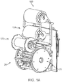
- FIG. 1A there is shown a perspective view of a crimping assembly 20 that includes three rolls 123, 124, 125 used to position a clean sheet of non-stick material between the crimping blades and a metal stent prior to crimping.
- upper roll 125 holds the sheet secured to a backing sheet.
- the sheet is drawn from the backing sheet by a rotating mechanism (not shown) within the crimper head 20.
- a second sheet is dispensed from the mid roll 124. After crimping, the first and second (used) sheets are collected by the lower roll 123.
- each metal stent may be covered in a thin, compliant protective sheath before crimping.
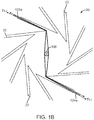
- FIG. 1B illustrates the positioning the first sheet 125a and second sheet 124a relative to the wedges 22 and a metal stent 100 within the aperture of the crimping assembly 20. As illustrated each of the two sheets are passed between two blades 22 on opposite sides of the stent 100 and a tension T1 and T2 applied to gather up excess sheet material as the iris of the crimping assembly is reduced in size via the converging blades 22.
- the dispensed sheets of non-stick material are used to avoid buildup of coating material on the crimper blades for stents coated with a therapeutic agent.
- the sheets 125a, 124a are replaced by a new sheet after each crimping sequence. By advancing a clean sheet after each crimp, accumulation of contaminating coating material from previously crimped stents is avoided.
- replaceable sheets stents having different drug coatings can be crimped using the same crimping assembly without risk of contamination or buildup of coating material from prior stent crimping.
- the art recognizes the mechanical problem as too different to provide helpful insights, therefore, despite a shared similarity in class of material.
- the balloon fabrication art provides only general guidance for one seeking to improve characteristics of a balloon-expanded, bio-absorbable polymeric scaffold.
- Polymer material considered for use as a polymeric scaffold may be described, through comparison with a metallic material used to form a stent, in some of the following ways.
- a suitable polymer has a low strength to weight ratio, which means more material is needed to provide an equivalent mechanical property to that of a metal. Therefore, struts must be made thicker and wider to have the strength needed.
- the scaffold also tends to be brittle or have limited fracture toughness.
- anisotropic and rate-dependant inelastic properties i.e., strength / stiffness of the material varies depending upon the rate at which the material is deformed
- a polymer particularly, bio-absorbable polymer such as PLLA or PLGA.
- a change in a polymeric scaffold pattern may affect not only the stiffness or lumen coverage of the scaffold in its deployed state supporting a lumen, but also the propensity for fractures to develop when the scaffold is crimped or being deployed. This means that, in comparison to a metallic stent, there is generally no assumption that can be made as to whether a changed scaffold pattern may not produce an adverse outcome, or require a significant change in a processing step (e.g., tube forming, laser cutting, crimping, etc.).
- a processing step e.g., tube forming, laser cutting, crimping, etc.
- the highly favorable, inherent properties of a metal (generally invariant stress/strain properties with respect to the rate of deformation or the direction of loading, and the material's ductile nature), which simplify the stent fabrication process, allow for inferences to be more easily drawn between a changed stent pattern and/or a processing step and the ability for the stent to be reliably manufactured with the new pattern and without defects when implanted within a living being.
- Non-uniform forces applied during a crimping process can cause irregular deformations in struts of a polymer scaffold, which can induce crack formation, and loss of strength.
- the invention provides a process and apparatus for crimping a polymer scaffold to a balloon.
- the word invention is used and/or features are presented as optional this should be interpreted in such a way that protection is sought for the invention as claimed.
- the polymer scaffold is expanded for placement within a lumen of the body by plastic deformation of the polymer scaffold.
- the crimping process used to place the scaffold on the balloon includes, in one embodiment, an initial diameter reduction followed by final crimp steps.
- the invention provides both a modified crimping apparatus and a modified process for crimping a polymer scaffold to reduce damage and/or improve batch yield for polymer scaffold-catheter assemblies following the crimping phase of a production process. Modifications include modifications to a crimping blade, interior supports for a scaffold and the sequence of steps included in crimping to achieve the desired results. All of these improvements used together, or only some have been found to improve results significantly.
- the invention addresses the problem of damage caused when a balloon expandable polymer scaffold is crimped to a deployment balloon.
- a polymer scaffold is placed in a crimping device for metallic stents, there is frequently occurring damage done to the scaffold structure by the forces acting on the surfaces of the scaffold through crimper blades as the scaffold is crimped to the balloon.
- a crimping device used for metallic stents uses metallic blades and in some cases blades with hardened tips. The devices are constructed in this way to allow frequent crimping of metallic structure without pitting or deformation of the blades when deforming struts of metallic stents.
- indentations raise concerns over crack propagation, especially for a brittle polymer like PLLA. Indentations are believed to occur mostly towards the end of the crimping sequence when the tips of the crimper blades are orientated more directly towards the scaffold surface.
- Polymer scaffolds are also more susceptible to irregular crimping forces that result in bent, twisted, or overlapping struts. These crimping problems are due to misalignment of the scaffold within the crimper. Static charge buildup on polymer surfaces are one cause for the misalignment, e.g., as when a polymer sheet slides over a polymer scaffold surface during crimping. However, it is also believed that misalignments that would normally be tolerated when crimping a metal stent can create irregular crimping of a polymer scaffold due to the proximity of struts in a polymeric scaffold.
- a method for crimping a polymer scaffold to a balloon including providing a crimping assembly for crimping the scaffold from a first diameter to a reduced second diameter, the crimping assembly including a plurality of movable blades, each blade having a hardness, a first side and a second side converging to form a tip, the tips being arranged to collectively form an iris about a rotational axis thereof, the iris defining a crimp aperture about which the movable blades are disposed; disposing a polymer material between edges of the blade tips and the scaffold surface to reduce the hardness in the edges; supporting the scaffold including inflating a balloon within the scaffold to provide interior support to the scaffold, whereby adjacent struts of the scaffold twisted irregularly by a crimper blade are supported by the balloon surface to deter one of the struts from overlapping or twisting irregularly relative to the other strut; and displacing
- a method for crimping a polymer scaffold to a balloon including providing a crimping assembly; providing a polymer coating on blade tips to soften a leading edge of the blade tips; supporting the scaffold during crimping by an inflated balloon within the scaffold wherein the balloon applies a radially outward pressure to provide a stabilizing pressure to a strut displacing out of plane or twisting due to uneven crimping forces applied to the strut or near the strut; and displacing the plurality of movable blades from the first diameter to the reduced second diameter; wherein the balloon pressure is adjusted as the scaffold diameter is reduced by the tip including the leading edge such that the radially directed outward force applied on the scaffold by the balloon supports the scaffold to avoid or compensate for irregular bending or twisting of scaffold structure.
- a method for crimping a polymer scaffold to a balloon including providing a crimping assembly for crimping the scaffold from a first diameter to a reduced second diameter, the crimping assembly including the plurality of movable blades, a first sheet of polymer film extending between a first and second pair of opposed blades such that a portion of the first sheet extends across an aperture formed by the iris, and a second sheet of polymer film extending between the first and second pair of opposed blades such that a portion of the second sheet also extends across the aperture; placing the scaffold on a balloon; disposing the scaffold and balloon in the aperture such that the scaffold and balloon are located between the first and second sheets; inflating the balloon; and displacing the plurality of movable blades from about the first diameter to about the reduced second diameter to reduce the diameter; wherein the balloon pressure is adjusted as the scaffold diameter is reduced by the tip such that the radially directed outward force applied on the scaffold by the balloon supports the scaffold to avoid or compensate for irregular
- a method for crimping a polymer scaffold to a balloon including placing a scaffold having a first diameter on a support balloon; inflating the support balloon to a pressure for supporting and stabilizing the scaffold at the first diameter while the scaffold is being crimped; crimping the scaffold from the first diameter to a second diameter while the first balloon is supported by the support balloon; replacing the support balloon with a balloon catheter after the scaffold is reduced to the second diameter; and crimping the scaffold to a third diameter, less than the second diameter while the scaffold is supported on the balloon catheter.
- an assembly for crimping a polymer scaffold to a balloon including a plurality of movable blades, each blade having a hardness, a first side and a second side converging to form an edge, the edges arranged to collectively form an iris about a rotational axis thereof, the iris defining a crimp aperture about which the movable blades are disposed; wherein the blade edge is one or both of a polymer coated to reduce the hardness of the blade, or formed as a blunted edge wherein the blunted edge is non-symmetrically disposed about a bisecting line defining a line of action of the blade when the crimping mechanism adjusts the iris from a first to a second diameter.
- a method for crimping a polymer scaffold to a balloon including placing a scaffold having a first diameter on a support balloon; the support balloon is pressurized to manipulate the orientation of the scaffold at first diameter.
- This orientation is used to position the metal marker beads relative to the crimp head for specific placement, with the use of a proximity sensor, e.g. a laser sensor, which is disposed within the crimp head. Lateral misplacement of the scaffold could lead to disparity between proximal and distal ends of the crimp blades.
- the scaffold is aligned precisely within the crimper head using the alignment system.
- a scaffold may be removed from the crimp head and rotated to a selected angular position after an initial crimp, or a subsequent reduced diameter before replacing a support balloon with the catheter delivery balloon.
- re-orienting the scaffold in this manner one can establish more uniformity in the crimp profile as the scaffold diameter is reduced.
- the motion of the sheets relative to the blades may produce a non-uniform crimp of the scaffold about its circumference due to twisting or pulling in torsion the scaffold by the sheets (particularly when a static charge is present).
- Rotation of the scaffold through an angle, e.g., 90 degrees, after a crimp may help to reduce problems caused by polymer sheets.
- the invention arose out of a need to solve a problem of high rejection rates for balloon expandable polymer scaffolds crimped to a deployment balloon.
- Polymer scaffolds were being rejected because the structure was being irregularly deformed by the crimper, e.g., struts overlapping each other or being twisted into abnormal shapes, and because there were a high number of cracks and/or indentations formed in the scaffold.
- This damage to the scaffold when crimped resulted in a relatively high probability of failure as one or more struts fractured when the scaffold is loaded by a vessel, or the scaffold expanded improperly, thereby not properly supporting a vessel.
- the causes for this damage while generally known were not easy to identify for purposes of spotting patterns or characteristic damage to the scaffold, in contrast to damage that would be caused if the crimper blades were not properly calibrated, bearings needed replacement, scaffold was not properly placed at a central portion of the crimper, etc.
- the nature of deformation of an article through externally applied forces may, in some situations, be inferred from the reaction forces applied by the article against the body, through which the external force is applied.
- the body applying the force to the article is programmed to enforce a displacement at a prescribed rate
- monitoring the changes in the force needed to maintain the enforced displacement can give clues as to how the body is being deformed.
- an operator can set the rate for crimping and monitor the applied force.
- the known methods for instrumentation are not capable of providing the level of accuracy needed to infer how individual struts are being deformed by crimper jaws.
- the operator therefore, has virtually no knowledge about how the scaffold's struts are being deformed within the crimper.
- the only knowledge that the operator has about how the scaffold might have been deformed when in the crimper occurs is after the scaffold is withdrawn from the crimper and visually inspected. At this point irreparable damage has occurred and the scaffold and catheter must be discarded.
- metal struts polymer struts are normally thicker and wider than metal struts, so that the polymer struts have about the same radially stiffness properties.
- the existing art pertaining to crimpers fails to adequately account for these differences.
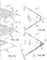
- FIGS. 2-4 are illustrations referred to show relationships between crimper blades and a scaffold during a crimping process when using a conventional crimping process.
- the crimper head is drawn as having only 8 blades each spanning 45 degrees.
- a more typical arrangement has 12 blades spanning 30 degrees each.
- FIGS. 2 and 3 are cross-sectional views of a crimper head and scaffold within the aperture of the crimper head showing the orientation of the blades relative to the scaffold when the aperture forms a first diameter and second, smaller diameter, respectively.
- the scaffold body 10 is disposed between the blades 22.
- the scaffold 10 is supported on the collapsed balloon 200 of the catheter when it is placed in the crimper head. Then, as the blade edges engage the scaffold the scaffold is lifted off the balloon as shown.
- This setup is typical setup for a crimping sequence for a metal stent, but with the metal stent replaced by a polymer scaffold.
- the blade edges are directed away from the scaffold surface so that only the more flat surface of the blade 22 abuts the scaffold surface when the aperture is at the first diameter. This means that the loading on the scaffold surface is distributed out more over the body because there is more surface-to-surface contact, thereby more likely avoiding blade indentations from forming in the scaffold.
- the scaffold diameter is much larger than the balloon profile, any slight misalignment, either with regards to the scaffold relative to catheter support, or the crimping blades not closing on the scaffold uniformly, can produce twisting or irregular bending as the scaffold is displaced off-center relative to the central crimping axis. The problem was found to reside with the lack of an interior, stabilizing support for the scaffold when it has the large initial diameter, e.g., 2.5 to 3 times the crimped diameter size.
- the edges of the blades are directed more towards the surface of the scaffold because the blades are forming an iris that is smaller in size than in FIG. 2 .
- the relatively sharp edges of the wedge-like blades 22 are bearing down on the scaffold surface. It is in the situation that indentations, cuts and gouges causing unacceptable structural damage can occur.
- any twisting, irregular bending, or strut overlapping has begun to occur when the scaffold is at its larger diameter ( FIG. 2 ), further twisting, bending and overlapping of struts can occur.
- any bending or twisting that has been initiated at the larger diameter is believed to become more pronounced or encouraged as the spacing between the struts is reduced and struts begin to abut each other.
- this problem of abutting struts is not usually present for a metal stent because either a metal stent strut is thinner or the diameter reduction required for crimping is less than for a polymer scaffold. In either case, there is more spacing between struts. Therefore, there is less chance that a misaligned strut will cause greater misalignment at smaller diameters because there is more available clearance between struts as the stent is reduced in diameter.
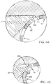
- FIGS. 4A and 4B are close up views of FIGS. 2 and 3 , respectively, showing the relative position of the blade edge 22b and surface 22a away from the edge 22b relative to the surface of the scaffold 10.
- FIG. 4B depicts a deformation, tearing or gouging being formed in the scaffold structure as a result of the edge 22b bearing down upon the scaffold. This situation is believed to occur when an edge of the blade catches the edge of a scaffold strut, such as a strut that was previously deformed or twisted, even slightly, out of position so that the blade edge 22b catches it.
- strut or crown 10' has been twisted and through abutment with strut 10" results in the struts or crowns overlapping each other. Once this interaction between struts begins and the diameter is reduced further, the problem can become worse and worse until the scaffold becomes unusable. As a result, both the scaffold and catheter supporting the scaffold is discarded.
- a "slight" misalignment means a misalignment that the art has tolerated in the past and assumed were present but not capable of significantly effecting how a metal stent would be deformed by the crimper as compared to the same stent when perfectly aligned with and coming into contact with the blades of the crimper.
- misalignment tolerance is understood by reference to information available from a manufacturer of a commercially available crimping device.
- One type of misalignment of crimper blades believed to cause unacceptable damage to polymer scaffold would be when one blade is not maintained flush with an adjacent blade, such that when the iris diameter is reduced a sharp leading edge is exposed. This sharp edge can then tear into, or cut across a polymer strut, e.g., resulting in the damage shown in FIGS. 12A-12B .
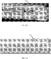
- FIGS. 11-12 and 14 are photographs showing damage to polymer scaffold using a known crimping process for metal stents.
- FIGS. 13 and 15 show, however, a marked improvement in crimping when processes according to the disclosure are used in place of the known crimping process.
- FIGS. 11-13 are photographs for the scaffold depicted in FIG. 5 .
- FIGS. 14-15 are photographs for the scaffold depicted in FIG. 10 .
- FIGS. 11A-11B show two types of defects in a crimped scaffold.
- FIG. 11A shows that the linking element connected to the crown is bent. This bent "Y" section of the scaffold (D3) caused the crimped scaffold to be rejected. The region where this bending D3 occurred is a known high stress area where fracture is more likely to occur in the deployed scaffold. For this reason, the scaffold is rejected.
- FIG. 11B shows a defect D3 that will cause this scaffold to be rejected as well.
- the defect D3 in FIG. 11B includes not only a bent "Y” section, but also a pinching of the crown. As can be seen in this photograph, an upper crown is pressing against the lower crown forming the "Y". The result is the struts are squeezed together beyond their designed bending ranges.
- FIGS. 12A and 12B are scanning electron microscope images showing abrasions, cuts, gouges and indentations (D3) in the scaffold due to the knife-like edge of the crimper blade bearing down on the scaffold. This damage D3 to the scaffold is likewise unacceptable and results in the scaffold being rejected.
- damage like that shown in both FIGS. 11 and 12 are likely present in the crimped scaffold. Indeed, before the invention there was a near 0% yield for scaffold that were devoid of the damages depicted in FIGS. 11-12 .
- FIGS. 14A-14C depicts damage observed for the scaffold described in FIG. 10 .
- the scaffold exhibits severe irregularity, e.g., bent and even flipped struts, overlapping struts and pinched struts.
- FIG. 14B while not showing the severity in bending and twisting as in the case of FIG. 14A , nonetheless is also an unacceptable crimping for a scaffold since Y or W elements at one circumferential station are being crimped at a different rate from another circumferential station. It is believed that if this scaffold were crimped further, overlapping, flipping or similar undesired deformation of the scaffold will occur.
- FIG. 14A the scaffold exhibits severe irregularity, e.g., bent and even flipped struts, overlapping struts and pinched struts.
- FIG. 14B while not showing the severity in bending and twisting as in the case of FIG. 14A , nonetheless is also an unacceptable crimping for a scaffold since Y or W
- FIGS. 14A-14B shows a close-up of overlapping struts (D4).
- This scaffold as was the case of the scaffold depicted in FIGS. 14A-14B , was rejected.
- the overlapping struts D4 in this section can result in improper deployment, as well as significant loss in stiffness and fracture toughness.
- a misalignment refers to either the scaffold bore axis not aligning with the crimper central axis or the scaffold not aligning properly with the blades of the crimping device axis as the iris is being closed onto the scaffold.
- a polymer scaffold, and in particular a misaligned polymer scaffold is more susceptible to damage within a crimper than a corresponding metal stent.
- a polymer scaffold that has a "slight" misalignment within the crimper has a far greater chance of becoming damaged than a metal stent.
- the need to avoid twisting, bending or indentations in struts of metal stents when in a crimper is known.
- a polymer scaffold surface has a much lower hardness than a metal stent surface.
- the polymer scaffold is more susceptible to local damage by the crimper blades. Moreover, due to the proximity of struts to each other (as required since thicker and wider struts are needed to provide equivalent stiffness to a metal stent), there is a greater chance of abutting struts which leads to out of plane twisting and overlapping scaffold structure in the crimped state. The affect of irregular or non-uniform crimping forces on a polymer scaffold are therefore more severe than in the case of a metal stent. The differences are most clearly evident in the instances of cracking and/or fracture in deployed polymer scaffolds that exhibit irregular twisting or bending and indentions.
- Crimping a polymer scaffold in the manner illustrated in FIGS. 2 and 3 was found to be inappropriate for these reasons. Scaffolds crimped in this manner are often damaged and of no use. In one example using a crimping device and crimping process for metal stents the yield was near 0%. When aspects of the invention were employed, the yield was increased to 80%.
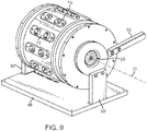
- FIG. 9 is a perspective view of such a crimping assembly 20 incorporating a crimping mechanism that includes a collection of blades, e.g., twelve 30 degree blades, that articulate circumferentially and radially where each blade is articulated radially and circumferentially in unison with the other blades by a two axis linking mechanism (combined radial and circumferential motion for each blade).
- the assembly thus includes a plurality of blades arranged to form an aperture 21 with variable diameter.
- the crimping assembly 20 includes a base 48, supports 50' and 50" and an arm 65 for causing the blades to move inwards or outwards for reducing or enlarging, respectively, the aperture 21 formed by the iris.
- the central axis for the crimping blades, or crimping axis for the assembly is drawn as axis 31 in FIG. 9 .
- a polymer scaffold is crimped using a crimper assembly that supplies sheets of polymer film between the scaffold and crimper blades.
- a crimper assembly that supplies sheets of polymer film between the scaffold and crimper blades.
- FIGS. 1A and 1B An example of this type of crimping assembly is illustrated in FIGS. 1A and 1B . It was found that the polymer sheet also helped to reduce indentations in scaffold surfaces since the polymer sheets effectively made the blade surfaces more compliant. However, disposing a polymer material between the blades and scaffold surface was not enough to reduce damage to the polymer scaffold. An unacceptably high number of damaged scaffolds still resulted when the crimped scaffold was removed from the crimper of FIGS. 1A-1B .
- a strut predisposed to twist or overlap with other struts refers to a strut that was previously slightly bent or twisted out of plane when the scaffold was at a larger diameter.
- a strut predisposed to twist or overlap with other struts refers to a strut that was previously slightly bent or twisted out of plane when the scaffold was at a larger diameter.
- balloon pressure is believed to provide a beneficial reacting pressure upon the luminal side of the strut, which can serve to limit a strut's potential to overlap or twist irregularly when a blade edge imparts a higher degree of force to a strut than the blade applied during an earlier crimping step.
- Balloon pressure helps to stabilize the scaffold during the initial phases of the crimping sequence.
- the scaffold is reduced from an over-deployed or deployed diameter to a diameter that about 2.5 to 3 times smaller in size.
- the deployed or over-deployed diameter there is little stabilizing support for the scaffold since its diameter is much larger than the deflated balloon catheter upon which the scaffold sits.
- any initial non-uniform applied crimping force, or misalignment e.g., due to a residual static charge on the polymer surface, can initiate irregular bending that becomes more pronounced when the scaffold diameter is reduced further.
- the balloon was inflated to support the scaffold from the interior, it was discovered that the irregular bending and twisting of struts were reduced substantially.
- the scaffold was more able to maintain a proper orientation with respective to the crimper axis.
- the uniform pressure applied by the balloon tended to balance-out any non-uniformity in the applied crimping force.
- the scaffold was formed from a radially expanded tube of PLLA.
- the scaffold had a strut pattern as shown in FIG. 5 , 6 and FIG. 10 .
- An iris crimper having similar actuating characteristics to the crimping assembly described in connection with FIG. 9 was used to pre-crimp and final crimp the scaffold to the balloon.
- a crimping process for a polymer scaffold having the scaffold pattern of structural rings, struts and linking elements shown in FIGS. 5 , 6 or 10 may proceed as follows.
- the scaffold is placed on a balloon and deionized, the polymer sheets disposed within the crimping aperture 21 are deionized, and the scaffold is placed with the crimper 20.
- the temperature of the crimper blades are raised to, or to about 48°C and allowed to stabilize at that temperature.
- the radiant and convective heat from the blades is relied on to raise the temperature of the scaffold when the scaffold is in the crimper. Hot air may also be introduced to raise the scaffold temperature.
- a polymer scaffold of the type illustrated in FIGS. 5 , 6 or 10 requires an initial diameter reduction or pre-crimp, a re-alignment or alignment check with balloon markers, followed by a final crimp procedure due to the initial large diameter of the polymer scaffold, which large diameter may correspond to a deployed or over deployed diameter for the scaffold.
- a polymer scaffold is formed in this way so that it can possess the polymer chain alignment most optimal for providing high stiffness and low recoil in the deployed state.
- This configuration also makes the crimping process more challenging because there is large diameter reduction needed (metal stents, in contrast, due not require this form of assembly due to the difference in material properties.
- Metal stents may be fabricated at a reduced diameter, which makes it far easier to crimp the metal stent to a balloon since the starting diameter is closer to the crimped diameter).
- a scaffold is reduced from a starting diameter of about .136 in to a crimped diameter of about .052 in.
- a scaffold is reduced form a starting diameter of about 9 mm to a crimped diameter of between about 2 and 3 mm.
- an anti-static filtered air gun is used to deionize the scaffold before and/or during pre-crimping. Before pre-crimp, the anti-static air gun is passed over the scaffold front to back to remove static charges on the scaffold. In one case, the anti-static filtered air gun is applied for 10 seconds to 1 minute along the scaffold. In another embodiment, the air gun deionizes the scaffold during pre-crimping. The anti-static filtered air gun is applied for 10 seconds to 1 minute along the scaffold.
- the crimping sequence for a 3.0 x 18 mm PLLA scaffold having the pattern illustrated in FIG. 5 is illustrated as an example.
- the initial pre-crimp moves the blades forming the iris from a starting diameter of .136 in to a diameter of .083 in where it remains for a 30 second dwell.
- This is stage 1.
- balloon pressure may be applied to stabilize the scaffold, in an amount of about 2 to 15 psi.
- the scaffold and balloon upon which the scaffold rests is then removed from the crimper and the alignment with balloon markers verified.
- the diameter reduction to .082 in loosely secures the scaffold to the balloon so that it can hold its place but is still capable of being adjusted relative to balloon markers.
- the scaffold is returned to the crimper.
- Stage 2 of the crimping sequence moves the blades forming the iris from to a .068 in and is held for 15 seconds.
- the balloon is inflated to about 17 to 100 psi.
- the balloon is deflated and the iris opened to allow the catheter to be removed.
- the scaffold receives a final alignment to the balloon markers.
- the scaffold and balloon are placed back into the crimper.
- Stage 3 reduces the diameter to .070 in with a 10 second dwell.
- the balloon is inflated to about 17 to 100 psi.
- the machine moves to Stage 4, where the balloon pressure is reduced to lower than about 15 psi and iris reduced to .047 in and held for a final 200 second dwell.
- the iris is opened and the catheter and scaffold removed.
- the scaffold is retained on the balloon and immediately placed into a sheath minimize recoil in the polymer scaffold.
- a balloon pressure during diameter reduction may be selected to provide support for the scaffold without imposing excessive stresses on the balloon material.
- a compliant and expendable support balloon held at a constant pressure may be used during the initial diameter reduction, as in the case of the scaffold of FIG. 10 .
- the balloon pressure may be adjusted by a controlled release of gas pressure as the scaffold diameter is decreased.
- the balloon pressure may be increased after an incremental diameter reduction is made, during a dwell period. By increasing balloon pressure immediately after an incremental crimp, any irregular deformations can be adjusted by supporting balloon pressure, which provides a uniform pressure to the inner surfaces of the scaffold to compensate for any tendency for a strut to irregular deformation. For example, a strut that was deformed inwardly can be pushed back into position when the balloon is inflated.
- a scaffold reduced in diameter from about 9 mm to about 2-3 mm has a 120 mm length.
- the crimping sequence may proceed as follows using a crimping station such as a crimping station described in U.S. application serial no. 12/831,878 (attorney docket no. 62571.425).
- a crimp process for the scaffold depicted in FIG. 9 is crimped at a temperature of about 48 degrees Celsius for PLLA scaffold material.
- the temperature may be lower.
- the scaffold temperature is raised via convection and radiation from the heated crimper blades.
- the 9 mm ID scaffold is placed on a 9-10 mm support balloon.
- This balloon is inflated through a sidearm of the balloon with 40-70 psi air to create a balloon OD of 8 mm.
- the scaffold is rotated about its axis while supported on the support or temporary balloon between intermediate crimping stages.
- the scaffold and support balloon are removed from the crimper head and the scaffold is rotated, e.g., about 45 degrees about its axis, then a second crimp is performed.
- the same step may be performed several times until the diameter is reached in which the temporary balloon is replaced by the balloon catheter.
- the rotation may be less than 30 degrees, or the angle extending between adjacent "Y" shape elements.
- the angle of rotation may also be the 1/2 angle between Y-shaped elements to compensate for a non-uniform crimping such as that depicted in FIG. 14B .
- a polymer coating is applied to edges of blades, rather than using tensioned polymer sheets as in FIG. 1B .
- the effect is to reduce the hardness of the blade surfaces that contacts the polymer scaffold, or to cause the crimper blade loading of the scaffold struts to by more widely distributed over the surface.
- the objective is to make the blade edge softer so that its hardness is closer to that of the relatively soft polymer surface. In doing so, the blade forces (especially at or near the blade edge) will be distributed over a greater portion of the surface of the scaffold (since the surface is made more soft) which should reduce indentations on the scaffold surface, especially when the iris diameter moves to the final crimp diameter ( FIG. 3 ).
- Hardness is meant to refer to the resistance of a surface to permanent shape change when a force is applied.
- hardness refers to indentation hardness, or the ability to resist a permanent indentation from forming. Since it is not desired to change properties of the polymer scaffold so as to affect its hardness, the hardness of the blade is changed, i.e., it is made softer, by applying a polymer coating of suitable hardness to the blade edge.
- the hardness of the coated blade to the scaffold surface, which is intended to mean the "effective" hardness of the blade, i.e., the hardness of the coated surface that comes into contact with the scaffold surface.
- This arrangement would perhaps be most ideal from the standpoint of avoiding indentations in the scaffold while ensuring the blades are capable of deforming the scaffold struts in the intended manner.
- reducing blade hardness to this degree would require more frequent maintenance of the blades as the coated blade edge would become deformed or removed from the blades relatively often (depending on the material used) following a production crimping run. Reducing blade hardness so that it is about at the hardness of the scaffold may also not be desired when crimping at elevated temperatures.
- the polymer coating used to match hardness may make it difficult to effectively or efficiently conduct heat from the blades to the scaffold in those cases where the scaffold is heated by heat conducted and radiated from the metal blades.
- the polymer coating may be polyurethane or any other relatively elastic polymer material.
- the coating thickness applied to blades may range from about 100 to 150 microns, depending on the material used.
- the thickness of the coating may be selected to make the edge of the crimper blades more soft but without causing thermal insulation problems.
- a polymer coating thickness may be maintained at a constant thickness, or having a tapered thickness so that damages caused by sharp edges are reduced yet the scaffold can be efficiently heated to a desired crimping temperature by way of blade radiation / conduction.
- a scaffold inserted within a crimper head exposed to crimper blades will obtain a temperature at about the glass transition temperature of the polymer, and more preferably between 5 or 10 degrees below the glass transition temperature without additional heating sources being required for a tapered polymer thickness over the blade edge contact length, or less than this length, with a maximum thickness being at or near the sharp tip being between about 100 and 150 microns.
- the coating is too thick or disposed over much of the tip of the blade, then heat convection from the blades to the scaffold may become impaired which makes scaffold heating through the crimp blades infeasible, or impractical for batch or production crimping.
- the hardness of the edge modified by the coating to reduce indentations from forming in the scaffold may also make the blade more susceptible to deformation (since the surface is softened), which may necessitate frequent maintenance of the polymer coated blades.
- the polymer coating may further, or in addition to, be evenly applied over the edge of the blade, or applied non-uniformly according to the shape or orientation of the blade relative to scaffold surface at the final crimp diameter.
- the coating may be applied over both the edge and the surface proximal the edge that contacts the scaffold when the iris is at a larger diameter. Or the coating may be limited to the edge to only compensate for damage believed to occur primarily when the iris approaches the final crimped diameter.
- the thickness and/or distribution of coating over the blade may be selected based on a need to maintain a minimum rate of heat convection across the contacting surface or radiated heat from the exposed metal surface to the scaffold surface, or based on the particular blade design and/or where in the crimping sequence damage is believe to most likely occur, e.g., at the final crimp or earlier in the crimping sequence.
- the blade edge may be configured to receive a removable polymer insert, or edge to facilitate more efficient upkeep and reduce downtimes over embodiments that use a polymer coating.
- a removable polymer insert or edge to facilitate more efficient upkeep and reduce downtimes over embodiments that use a polymer coating.
- An example of such an insert is described in US 7389670 . Inserts, as opposed to an applied coating, however, can only be made so small and/or thin to enable the insert to be easily secured to, and removed from the blade edge.
- a blade that uses a polymer insert e.g., as disclosed in US 7389670 may introduce thermal insulation problems between the blades and the scaffold. As such, it may not be desirable to use an insert when the metal surfaces of the blades are needed to conduct heat to the polymer scaffold.
- FIGS. 7A and 7B Embodiments are illustrated in FIGS. 7A and 7B .
- the coating 50 on blade 22 has a first thickness t2 at the leading edge 22b which tapers to a third, reduce thickness t3 away from the leading edge at surface 22a.
- a generally constant thickness "t1" of coating 50 is applied at the edge 22b and over the surface 22a, which contacts the strut surface before the leading edge 22b during the crimping process.
- FIG. 7C depicts a blade 22' formed to receive a polymer insert 51.
- the insert has about the same thickness t4 over the distance the scaffold makes contact with the blade surface and is shaped to approximately form the edge and surface dimensions of the blades of FIGS. 7A-7B .
- the insert can thermally insulate the metal blade from the scaffold, which is not desired when blade heat is used to heat the scaffold as in the preferred embodiments.
- a coating is used which can have a thickness that does not adversely impact heat convection or radiation from the blades to the scaffold.
- the blade edge 22b may be reshaped to provide a more blunted or rounded edge to reduce force concentrations on the scaffold surface when the iris approaches the final crimped diameter.
- the objective sought for such a blade tip may be two-fold. First, by providing a more rounded or blunted edge or tip (a rounded edge being one embodiment of a blunted edge) the surface-to-surface contact area between the blade and scaffold can be made more constant throughout the crimping steps. This has the effect of reducing damaging force concentrations produced by a narrow blade edge, which force concentrations result from a narrow contact area over which the blade applies the crimping force near the final crimping diameter.
- any previously irregularly deformed scaffold struts caused by prior crimping steps in a crimping sequence will have less tendency of being caught, grabbed, or pushed outwardly or inwardly by a blade edge. It is believed that significant damage may occur during the final crimping steps from this type of interaction between a blade edge and a previously deformed strut.
- FIGS. 8A and 8B An example of these embodiments is illustrated in FIGS. 8A and 8B (the width of the blade 24 is exaggerated in this view, as compared to FIG.S 7A-7C , for ease of illustration).
- These drawings show a blade 24 edge that has been modified to make it blunter. In these examples the edge is made rounded.
- the blade edge 24b has a curvature defined by a radius of curvature R with the center of the circle being offset by a distance "d" from a bisecting line 37 of the converging surfaces 38, 39 that define the width of a wedge that terminates at a reference point "p". For example, if there are twelve crimper blades that cooperate to form the iris, then each blade defines a wedge spanning 30 degrees.
- the angle ⁇ in FIG. 8B is 15 degrees.
- the bisecting line 37 may correspond to the line of action of the blade 24 when it moves inward by the mechanism of the crimping assembly ( FIG. 9 ).
- the blade edge may be asymmetric with respect to the bisecting line 37.
- the blunt edge 24b of the blade 24 more or less maintains the same amount of surface-to-surface contact with the scaffold surface as the preceding surface 24a did when the scaffold had a larger diameter.
- force concentrations on the scaffold surface resulting in indentations should be reduced.
- the surface 24a, which contacts the scaffold surface at larger radii of the iris, is sloped to provide a gradual change in curvature leading to the radius of curvature at the edge 24b. Abrupt changes in the surface contour of the blade 24 are not desired so that force concentrations can be avoided when the blade bears down on the scaffold.
- FIG. 8B shows a polymer coating 52 applied to the blunted edge, which may be beneficial as a measure to form a more circular iris at the smaller diameters, or to reduce the blade hardness.
- the blade of FIG. 8A may still damage the scaffold when it abuts the relatively soft surface of the scaffold.
- the blade 24 has about the same surface contours as blade 22 without the coating applied.
- the polymer coating is formed to mimic the sharp edge of the convention blade tip, the polymer used for coating 52 may be less elastic or harder since it is formed into a narrow edge. In this way, the polymer edge will have more ability to retain its shape after several scaffold are crimped using a blade configured in this manner.
- a blunted, asymmetric edge like that shown in FIGS. 8A-8B relating to avoiding twisting, bending or overlapping struts.
- a relatively pointed blade edge e.g., as depicted in US7389670
- it can contact or catch a side surface of a strut to cause the strut to bend outwardly or inwardly, especially when the strut was previously bent outwardly or inwardly when the scaffold was being crimped at a larger diameter.
- the edge will have more of a tendency to slide over the edge as the iris diameter is decreased, rather than catching or grabbing the previously bent or twisted strut at its side surface.
- a scaffold has the scaffold pattern described in U.S. Application Serial No. 12/447,758 ( US 2010/0004735 ).
- Other examples of scaffold patterns suitable for PLLA are found in US 2008/0275537 .
- FIG. 5 shows a detailed view of an intermediate portion 216 of a strut pattern 200 depicted in US 2010/0004735 .
- the intermediate portion includes rings 212 with linear ring struts 230 and curved hinge elements 232.
- the ring struts 230 are connected to each other by hinge elements 232.
- the hinge elements 232 are adapted to flex, which allows the rings 212 to move from a non-deformed configuration to a deformed configuration.
- Line B--B lies on a reference plane perpendicular to the central axis 224 depicted in US 2010/0004735 .
- each ring strut 230 is oriented at a non-zero angle X relative to the reference plane.
- the non-zero angle X is between 20 degrees and 30 degrees, and more narrowly at or about 25 degrees.
- the ring struts 230 are oriented at an interior angle Y relative to each other prior to crimping.
- the interior angle Y is between 120 degrees and 130 degrees, and more narrowly at or about 125 degrees.
- having the interior angle be at least 120 degrees results in high hoop strength when the scaffold is deployed. Having the interior angle be less than 180 degrees allows the scaffold to be crimped while minimizing damage to the scaffold struts during crimping, and may also allow for expansion of the scaffold to a deployed diameter that is greater than its initial diameter prior to crimping.
- Link struts 234 connect the rings 212.
- the link struts 234 are oriented parallel or substantially parallel to a bore axis of the scaffold.
- the ring struts 230, hinge elements 232, and link struts 234 define a plurality of W-shape closed cells 236.
- the boundary or perimeter of one W-shape closed cell 236 is darkened in FIG. 5 for clarity. In FIG. 5 , the W-shapes appear rotated 90 degrees counterclockwise.
- Each of the W-shape closed cells 236 is immediately surrounded by six other W-shape closed cells 236, meaning that the perimeter of each W-shape closed cell 236 merges with a portion of the perimeter of six other W-shape closed cells 236.
- Each W-shape closed cell 236 abuts or touches six other W-shape closed cells 236.
- each W-shape closed cell 236 includes eight of the ring struts 230, two of the link struts 234, and ten of the hinge elements 232.
- Four of the eight ring struts form a proximal side of the cell perimeter and the other four ring struts form a distal side of the cell perimeter.
- the opposing ring struts on the proximal and distal sides are parallel or substantially parallel to each other.
- Within each of the hinge elements 232 there is an intersection point 238 toward which the ring struts 230 and link struts 234 converge. There is an intersection point 238 adjacent each end of the ring struts 230 and link struts 234.
- the distances 240 between the intersection points adjacent the ends of rings struts 230 are the same or substantially the same for each ring strut 230 in the intermediate portion 216 of the strut pattern 200.
- the distances 242 are the same or substantially the same for each link strut 234 in the intermediate portion 216.
- the ring struts 230 have widths 237 that are uniform in dimension along the individual lengthwise axis 213 of the ring strut.
- the ring strut widths 234 are between 0.15 mm and 0.18 mm, and more narrowly at or about 0.165 mm.
- the link struts 234 have widths 239 that are also uniform in dimension along the individual lengthwise axis 213 of the link strut.
- the link strut widths 239 are between 0.11 mm and 0.14 mm, and more narrowly at or about 0.127 mm.
- the ring struts 230 and link struts 234 have the same or substantially the same thickness in the radial direction, which is between 0.10 mm and 0.18 mm, and more narrowly at or about 0.152 mm.
- each W-shape closed cell 236 has an axial dimension 244 parallel to line A--A and a circumferential dimension 246 parallel to line B--B.
- the axial dimension 244 is constant or substantially constant with respect to circumferential position within each W-shape closed cell 236 of the intermediate portion 216. That is, axial dimensions 244A adjacent the top and bottom ends of the cells 236 are the same or substantially the same as axial dimensions 244B further away from the ends.
- the axial and circumferential dimensions 244, 246 are the same among the W-shape closed cells 236 in the intermediate portion 216.
- the strut pattern for a scaffold that comprises linear ring struts 230 and linear link struts 234 formed from a radially expanded and axially extended polymer tube.
- the ring struts 230 define a plurality of rings 212 capable of moving from a non-deformed configuration to a deformed configuration. Each ring has a center point, and at least two of the center points define the scaffold central axis.
- the link struts 234 are oriented parallel or substantially parallel to the scaffold central axis.
- the link struts 234 connect the rings 212 together.
- the link struts 232 and the ring struts 230 defining W-shape closed cells 236.
- Each W-shaped cell 236 abuts other W-shaped cells.
- the ring struts 230 and hinge elements 232 on each ring 212 define a series of crests and troughs that alternate with each other.
- Each crest on each ring 212 is connected by one of the link struts 234 to another crest on an immediately adjacent ring, thereby forming an offset "brick" arrangement of the W-shaped cells.
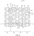
- each ring 305 being interconnected by horizontal linking elements 355.
- the bending elements 320, 315, 335, 340, 345 form the cells 310.
- the cells are connected at ends 360.
- a scaffold has a scaffold pattern as depicted in FIG. 10 .
- Examples of this scaffold pattern as described in U.S. patent Application Serial No. 12/561,971 (attorney docket number 62571.370).
- the scaffold pattern 400 includes a plurality of zig-zag like annular bands 306, 308. Each annular band is connected by a horizontal linking element 304.
Landscapes
- Health & Medical Sciences (AREA)
- Engineering & Computer Science (AREA)
- Biomedical Technology (AREA)
- Cardiology (AREA)
- Oral & Maxillofacial Surgery (AREA)
- Transplantation (AREA)
- Heart & Thoracic Surgery (AREA)
- Vascular Medicine (AREA)
- Life Sciences & Earth Sciences (AREA)
- Animal Behavior & Ethology (AREA)
- General Health & Medical Sciences (AREA)
- Public Health (AREA)
- Veterinary Medicine (AREA)
- Mechanical Engineering (AREA)
- Media Introduction/Drainage Providing Device (AREA)
- Materials For Medical Uses (AREA)
Priority Applications (1)
| Application Number | Priority Date | Filing Date | Title |
|---|---|---|---|
| EP16207622.8A EP3184085B1 (en) | 2010-08-23 | 2011-08-17 | Reducing crimping damage to polymer scaffold |
Applications Claiming Priority (2)
| Application Number | Priority Date | Filing Date | Title |
|---|---|---|---|
| US12/861,719 US8539663B2 (en) | 2010-08-23 | 2010-08-23 | Reducing crimping damage to polymer scaffold |
| PCT/US2011/048117 WO2012027172A2 (en) | 2010-08-23 | 2011-08-17 | Reducing crimping damage to polymer scaffold |
Related Child Applications (1)
| Application Number | Title | Priority Date | Filing Date |
|---|---|---|---|
| EP16207622.8A Division EP3184085B1 (en) | 2010-08-23 | 2011-08-17 | Reducing crimping damage to polymer scaffold |
Publications (2)
| Publication Number | Publication Date |
|---|---|
| EP2608751A2 EP2608751A2 (en) | 2013-07-03 |
| EP2608751B1 true EP2608751B1 (en) | 2017-01-04 |
Family
ID=44533198
Family Applications (2)
| Application Number | Title | Priority Date | Filing Date |
|---|---|---|---|
| EP11749667.9A Not-in-force EP2608751B1 (en) | 2010-08-23 | 2011-08-17 | Reducing crimping damage to polymer scaffold |
| EP16207622.8A Active EP3184085B1 (en) | 2010-08-23 | 2011-08-17 | Reducing crimping damage to polymer scaffold |
Family Applications After (1)
| Application Number | Title | Priority Date | Filing Date |
|---|---|---|---|
| EP16207622.8A Active EP3184085B1 (en) | 2010-08-23 | 2011-08-17 | Reducing crimping damage to polymer scaffold |
Country Status (5)
| Country | Link |
|---|---|
| US (4) | US8539663B2 (cg-RX-API-DMAC7.html) |
| EP (2) | EP2608751B1 (cg-RX-API-DMAC7.html) |
| JP (2) | JP5880982B2 (cg-RX-API-DMAC7.html) |
| CN (2) | CN103167846B (cg-RX-API-DMAC7.html) |
| WO (1) | WO2012027172A2 (cg-RX-API-DMAC7.html) |
Families Citing this family (68)
| Publication number | Priority date | Publication date | Assignee | Title |
|---|---|---|---|---|
| US8747879B2 (en) | 2006-04-28 | 2014-06-10 | Advanced Cardiovascular Systems, Inc. | Method of fabricating an implantable medical device to reduce chance of late inflammatory response |
| US7971333B2 (en) | 2006-05-30 | 2011-07-05 | Advanced Cardiovascular Systems, Inc. | Manufacturing process for polymetric stents |
| US20140107761A1 (en) | 2004-07-26 | 2014-04-17 | Abbott Cardiovascular Systems Inc. | Biodegradable stent with enhanced fracture toughness |
| US8597716B2 (en) | 2009-06-23 | 2013-12-03 | Abbott Cardiovascular Systems Inc. | Methods to increase fracture resistance of a drug-eluting medical device |
| US7731890B2 (en) | 2006-06-15 | 2010-06-08 | Advanced Cardiovascular Systems, Inc. | Methods of fabricating stents with enhanced fracture toughness |
| US20070156230A1 (en) | 2006-01-04 | 2007-07-05 | Dugan Stephen R | Stents with radiopaque markers |
| US8002817B2 (en) * | 2007-05-04 | 2011-08-23 | Abbott Cardiovascular Systems Inc. | Stents with high radial strength and methods of manufacturing same |
| US8568471B2 (en) | 2010-01-30 | 2013-10-29 | Abbott Cardiovascular Systems Inc. | Crush recoverable polymer scaffolds |
| US8808353B2 (en) | 2010-01-30 | 2014-08-19 | Abbott Cardiovascular Systems Inc. | Crush recoverable polymer scaffolds having a low crossing profile |
| US8261423B2 (en) | 2010-04-30 | 2012-09-11 | Abbott Cardiovascular Systems Inc. | Methods for crimping a polymeric stent onto a delivery balloon |
| US8539663B2 (en) * | 2010-08-23 | 2013-09-24 | Abbott Cardiovascular Systems Inc. | Reducing crimping damage to polymer scaffold |
| US9345602B2 (en) | 2010-09-23 | 2016-05-24 | Abbott Cardiovascular Systems Inc. | Processes for making crush recoverable polymer scaffolds |
| US8595913B2 (en) | 2010-09-30 | 2013-12-03 | Advanced Cardiovascular Systems, Inc. | Stent crimping methods |
| CN103607979B (zh) | 2011-04-18 | 2017-04-12 | 艾博特心血管系统公司 | 用于聚合物支架的均匀卷曲和展开的方法 |
| US9199408B2 (en) | 2012-04-03 | 2015-12-01 | Abbott Cardiovascular Systems Inc. | Uniform crimping and deployment methods for polymer scaffold |
| US8961848B2 (en) | 2011-04-18 | 2015-02-24 | Abbott Cardiovascular Systems Inc. | Methods for increasing a retention force between a polymeric scaffold and a delivery balloon |
| US20120290063A1 (en) | 2011-05-09 | 2012-11-15 | Abbott Cardiovascular Systems Inc. | Method of Increasing Stent Retention of Bioabsorbable Scaffolding with a Sheath |
| US8752265B2 (en) | 2011-05-13 | 2014-06-17 | Abbott Cardiovascular Systems Inc. | Methods for crimping a polymeric scaffold to a delivery balloon and achieving stable mechanical properties in the scaffold after crimping |
| US8414528B2 (en) * | 2011-05-27 | 2013-04-09 | Abbott Cardiovascular Systems Inc. | Polymer scaffold sheaths |
| US8852257B2 (en) | 2011-06-21 | 2014-10-07 | Abbott Cardiovascular Systems Inc. | Sheaths used with polymer scaffold |
| US8726483B2 (en) | 2011-07-29 | 2014-05-20 | Abbott Cardiovascular Systems Inc. | Methods for uniform crimping and deployment of a polymer scaffold |
| US9254212B2 (en) | 2012-04-06 | 2016-02-09 | Abbott Cardiovascular Systems Inc. | Segmented scaffolds and delivery thereof for peripheral applications |
| US9724219B2 (en) | 2012-10-04 | 2017-08-08 | Abbott Cardiovascular Systems Inc. | Method of uniform crimping and expansion of medical devices |
| US9937068B2 (en) * | 2012-10-25 | 2018-04-10 | Arterial Remodeling Technologies Sa | Crimping method for bioresorbable stents |
| US9072590B2 (en) | 2012-12-07 | 2015-07-07 | Abbott Cardiovascular Systems Inc. | Sheaths reducing recoil and loss of retention for polymer scaffolds crimped to balloons |
| US9440317B2 (en) | 2013-01-07 | 2016-09-13 | Abbott Cardiovascular Systems Inc. | Post-crimping inspection of scaffolds mounted on scaffold delivery systems |
| US20140277331A1 (en) | 2013-03-13 | 2014-09-18 | Abbott Cardiovascular Systems Inc. | Reducing Recoil in Peripherally-Implanted Scaffolds |
| US10039656B2 (en) | 2013-06-05 | 2018-08-07 | Abbott Cardiovascular Systems Inc. | Coupled scaffold segments |
| US9788983B2 (en) | 2013-06-21 | 2017-10-17 | Abbott Cardiovascular Systems Inc. | Removable sheath assembly for a polymer scaffold |
| US9675483B2 (en) | 2013-06-21 | 2017-06-13 | Abbott Cardiovascular Systems Inc. | Protective sheath assembly for a polymer scaffold |
| US9717609B2 (en) | 2013-08-01 | 2017-08-01 | Abbott Cardiovascular Systems Inc. | Variable stiffness stent |
| US10098771B2 (en) | 2013-09-25 | 2018-10-16 | Abbott Cardiovascular Systems Inc. | Clip sheath for a polymer scaffold |
| US9913958B2 (en) | 2014-02-28 | 2018-03-13 | Abbott Cardiovascular Systems Inc. | Protective sheaths for medical devices |
| US9364361B2 (en) | 2014-03-13 | 2016-06-14 | Abbott Cardiovascular Systems Inc. | Striped sheaths for medical devices |
| US10195025B2 (en) * | 2014-05-12 | 2019-02-05 | Edwards Lifesciences Corporation | Prosthetic heart valve |
| US10478600B2 (en) | 2014-05-28 | 2019-11-19 | Machine Solutions, Inc. | Segmental crimper having individually heated crimper segments and method of using the same |
| US10022906B2 (en) | 2014-07-30 | 2018-07-17 | Abbott Cardiovascular Systems Inc. | Methods for solid phase processing of tubes and medical devices made from the processed tubes |
| US9931787B2 (en) | 2014-09-18 | 2018-04-03 | Abbott Cardiovascular Systems Inc. | Crimping polymer scaffolds |
| WO2016044788A2 (en) | 2014-09-18 | 2016-03-24 | Abbott Cardiovascular Systems Inc. | Thermal processing of polymer scaffolds |
| CN104644293B (zh) * | 2014-12-30 | 2017-11-14 | 上海百心安生物技术有限公司 | 一种血管支架的压握方法及压握结构 |
| US9918857B2 (en) | 2015-01-14 | 2018-03-20 | Abbott Cardiovascular Systems Inc. | Scaffold having a shaped strut and methods for shaping scaffold struts |
| US9999527B2 (en) | 2015-02-11 | 2018-06-19 | Abbott Cardiovascular Systems Inc. | Scaffolds having radiopaque markers |
| US9700443B2 (en) | 2015-06-12 | 2017-07-11 | Abbott Cardiovascular Systems Inc. | Methods for attaching a radiopaque marker to a scaffold |
| TWI621505B (zh) * | 2015-06-29 | 2018-04-21 | 聖高拜磨料有限公司 | 研磨物品及形成方法 |
| US9908297B2 (en) | 2015-08-20 | 2018-03-06 | Abbott Cardiovascular Systems Inc. | Scaffolds having variable wall thickness |
| JP6639848B2 (ja) * | 2015-09-25 | 2020-02-05 | テルモ株式会社 | バルーン折り畳み機およびバルーン折り畳み方法 |
| WO2017051877A1 (ja) * | 2015-09-25 | 2017-03-30 | テルモ株式会社 | バルーン折り畳み機およびバルーン折り畳み方法 |
| WO2017051878A1 (ja) * | 2015-09-25 | 2017-03-30 | テルモ株式会社 | バルーン折り畳み機およびバルーン折り畳み方法 |
| JP6578174B2 (ja) * | 2015-09-25 | 2019-09-18 | テルモ株式会社 | バルーン折り畳み機およびバルーン折り畳み方法 |
| JP6623014B2 (ja) * | 2015-09-25 | 2019-12-18 | テルモ株式会社 | バルーン折り畳み機及びバルーン折り畳み方法 |
| JP6545057B2 (ja) * | 2015-09-25 | 2019-07-17 | テルモ株式会社 | バルーン折り畳み機 |
| US20170105856A1 (en) | 2015-10-16 | 2017-04-20 | Abbott Cardiovascular Systems Inc. | Non-circular radiopaque markers and methods for attaching a marker to a scaffold |
| US9956099B2 (en) | 2015-12-17 | 2018-05-01 | Abbott Cardiovascular Systems Inc. | Thin-walled scaffolds having reduced crimp profile and carrying radiopaque markers |
| US10143573B2 (en) | 2015-12-17 | 2018-12-04 | Abbott Cardiovascular Systems Inc. | Thin-walled scaffolds having flexible distal end |
| US9861507B2 (en) | 2015-12-17 | 2018-01-09 | Abbott Cardiovascular Systems Inc. | Thin-walled scaffolds having modified marker structure near distal end |
| CN108882985B (zh) | 2015-12-17 | 2021-08-03 | 雅培心血管系统有限公司 | 薄壁支架 |
| US10010653B2 (en) | 2016-02-05 | 2018-07-03 | Abbott Cardiovascular Systems Inc. | Methods for increasing coating strength to improve scaffold crimping yield |
| US10716691B2 (en) * | 2016-06-24 | 2020-07-21 | Edwards Lifesciences Corporation | Compact crimping device |
| US10660773B2 (en) | 2017-02-14 | 2020-05-26 | Abbott Cardiovascular Systems Inc. | Crimping methods for thin-walled scaffolds |
| US10709589B2 (en) | 2017-05-09 | 2020-07-14 | Abbott Cardiovascular Systems Inc. | Accelerated aging for polymeric scaffolds |
| CN107638238B (zh) * | 2017-10-27 | 2023-12-19 | 上海百心安生物技术股份有限公司 | 一种压握装置和压握方法 |
| US10555825B2 (en) | 2017-11-09 | 2020-02-11 | Abbott Cardiovascular Systems Inc. | Rotation of a medical device during crimping |
| US10967556B2 (en) | 2018-06-11 | 2021-04-06 | Abbott Cardiovascular Systems Inc. | Uniform expansion of thin-walled scaffolds |
| CN110478095B (zh) * | 2019-08-26 | 2025-10-17 | 上海翰凌医疗器械有限公司 | 一种压握机 |
| WO2021194976A1 (en) | 2020-03-26 | 2021-09-30 | Medtronic, Inc. | Clamshell iris-style crimper for medical devices |
| US11844713B2 (en) * | 2020-08-06 | 2023-12-19 | Medtronic, Inc. | Iris-style crimpers for medical devices |
| WO2025142581A1 (ja) * | 2023-12-26 | 2025-07-03 | テルモ株式会社 | クリンプ方法、バルーンカテーテルの製造方法、生体留置物、及びクリンプ装置 |
| CN119388733B (zh) * | 2024-12-31 | 2025-03-14 | 复星科技集团有限公司 | 一种紫外光固化软管干料自动折叠设备及折叠方法 |
Family Cites Families (61)
| Publication number | Priority date | Publication date | Assignee | Title |
|---|---|---|---|---|
| US5261263A (en) | 1992-12-21 | 1993-11-16 | Whitesell Eric J | Crimping pliers with radially opposed jaws |
| US5836965A (en) | 1994-10-19 | 1998-11-17 | Jendersee; Brad | Stent delivery and deployment method |
| US5913871A (en) | 1996-09-25 | 1999-06-22 | Medtronic, Inc. | Balloon modification for improved stent fixation and deployment |
| US5906759A (en) * | 1996-12-26 | 1999-05-25 | Medinol Ltd. | Stent forming apparatus with stent deforming blades |
| US5976181A (en) | 1997-09-22 | 1999-11-02 | Ave Connaught | Balloon mounted stent and method therefor |
| US6063092A (en) | 1998-04-07 | 2000-05-16 | Medtronic Inc. | Heat set and crimping process to optimize stent retention |
| US6296655B1 (en) | 1998-04-27 | 2001-10-02 | Advanced Cardiovascular Systems, Inc. | Catheter balloon with biased multiple wings |
| US6360577B2 (en) | 1999-09-22 | 2002-03-26 | Scimed Life Systems, Inc. | Apparatus for contracting, or crimping stents |
| US6629350B2 (en) | 2000-06-08 | 2003-10-07 | Tom Motsenbocker | Stent crimping apparatus and method |
| US6840081B2 (en) * | 2000-08-10 | 2005-01-11 | Advanced Cardiovascular Systems, Inc. | Assembly for crimping an intraluminal device or measuring the radial strength of the intraluminal device and method of use |
| AU6357501A (en) | 2000-08-23 | 2002-02-28 | Cordis Corporation | Low profile mounting method for low profile balloon expandable stents |
| ATE442112T1 (de) | 2001-02-16 | 2009-09-15 | Cordis Corp | Ballonkatheter-stentapplikationssystem mit furchen |
| US7572270B2 (en) | 2001-02-16 | 2009-08-11 | Cordis Corporation | Balloon catheter stent delivery system with ridges |
| US6783542B2 (en) | 2001-02-22 | 2004-08-31 | Scimed Life Systems, Inc | Crimpable balloon/stent protector |
| US6739033B2 (en) | 2001-03-29 | 2004-05-25 | Scimed Life Systems, Inc. | Thermal regulation of a coated work-piece during the reconfiguration of the coated work-piece |
| US6666880B1 (en) | 2001-06-19 | 2003-12-23 | Advised Cardiovascular Systems, Inc. | Method and system for securing a coated stent to a balloon catheter |
| US6805703B2 (en) | 2001-09-18 | 2004-10-19 | Scimed Life Systems, Inc. | Protective membrane for reconfiguring a workpiece |
| US6863683B2 (en) | 2001-09-19 | 2005-03-08 | Abbott Laboratoris Vascular Entities Limited | Cold-molding process for loading a stent onto a stent delivery system |
| AU2003241129A1 (en) | 2002-06-13 | 2003-12-31 | Existent, Inc. | Guidewire system |
| US6745445B2 (en) | 2002-10-29 | 2004-06-08 | Bard Peripheral Vascular, Inc. | Stent compression method |
| US20050118344A1 (en) | 2003-12-01 | 2005-06-02 | Pacetti Stephen D. | Temperature controlled crimping |
| JP2007512908A (ja) | 2003-12-01 | 2007-05-24 | アドヴァンスド カーディオヴァスキュラー システムズ, インコーポレイテッド | 温度調整式圧着法 |
| US7207204B2 (en) * | 2004-02-26 | 2007-04-24 | Boston Scientific Scimed, Inc. | Crimper |
| US7143625B2 (en) * | 2004-04-16 | 2006-12-05 | Boston Scientific Scimed, Inc. | Stent crimper |
| US7021114B2 (en) | 2004-04-16 | 2006-04-04 | Boston Scientific Scimed, Inc. | Stent crimper |
| US7389670B1 (en) | 2004-07-26 | 2008-06-24 | Abbott Laboratories | Stent crimping system |
| US8012402B2 (en) | 2008-08-04 | 2011-09-06 | Abbott Cardiovascular Systems Inc. | Tube expansion process for semicrystalline polymers to maximize fracture toughness |
| US8597716B2 (en) | 2009-06-23 | 2013-12-03 | Abbott Cardiovascular Systems Inc. | Methods to increase fracture resistance of a drug-eluting medical device |
| US7731890B2 (en) | 2006-06-15 | 2010-06-08 | Advanced Cardiovascular Systems, Inc. | Methods of fabricating stents with enhanced fracture toughness |
| US9283099B2 (en) | 2004-08-25 | 2016-03-15 | Advanced Cardiovascular Systems, Inc. | Stent-catheter assembly with a releasable connection for stent retention |
| US7316148B2 (en) * | 2005-02-15 | 2008-01-08 | Boston Scientific Scimed, Inc. | Protective sheet loader |
| US7563400B2 (en) | 2005-04-12 | 2009-07-21 | Advanced Cardiovascular Systems, Inc. | Method of stent mounting to form a balloon catheter having improved retention of a drug delivery stent |
| US7947207B2 (en) * | 2005-04-12 | 2011-05-24 | Abbott Cardiovascular Systems Inc. | Method for retaining a vascular stent on a catheter |
| US7763198B2 (en) | 2005-04-12 | 2010-07-27 | Abbott Cardiovascular Systems Inc. | Method for retaining a vascular stent on a catheter |
| US7743481B2 (en) | 2005-04-29 | 2010-06-29 | Arterial Remodelling Technologies, Inc. | Stent crimping |
| US7530253B2 (en) * | 2005-09-09 | 2009-05-12 | Edwards Lifesciences Corporation | Prosthetic valve crimping device |
| US7951185B1 (en) | 2006-01-06 | 2011-05-31 | Advanced Cardiovascular Systems, Inc. | Delivery of a stent at an elevated temperature |
| US20090076594A1 (en) | 2006-03-14 | 2009-03-19 | Patrick Sabaria | Method of monitoring positioning of polymer stents |
| US7761968B2 (en) | 2006-05-25 | 2010-07-27 | Advanced Cardiovascular Systems, Inc. | Method of crimping a polymeric stent |
| US20070282433A1 (en) | 2006-06-01 | 2007-12-06 | Limon Timothy A | Stent with retention protrusions formed during crimping |
| US8333000B2 (en) * | 2006-06-19 | 2012-12-18 | Advanced Cardiovascular Systems, Inc. | Methods for improving stent retention on a balloon catheter |
| US20080033523A1 (en) | 2006-07-10 | 2008-02-07 | Gale David C | Stent crack reduction |
| US20080033524A1 (en) | 2006-07-11 | 2008-02-07 | Gale David C | Heated balloon assembly for delivery of polymeric stents |
| US7886419B2 (en) * | 2006-07-18 | 2011-02-15 | Advanced Cardiovascular Systems, Inc. | Stent crimping apparatus and method |
| EP2076211A4 (en) * | 2006-10-20 | 2015-07-22 | Elixir Medical Corp | LUMINOUS PROSTHESES AND METHODS OF COATING THEREOF |
| US20080127707A1 (en) | 2006-11-30 | 2008-06-05 | Abbott Laboratories | Stent crimping assembly and method |
| US8099849B2 (en) | 2006-12-13 | 2012-01-24 | Abbott Cardiovascular Systems Inc. | Optimizing fracture toughness of polymeric stent |
| US8182890B2 (en) | 2007-01-19 | 2012-05-22 | Elixir Medical Corporation | Biodegradable endoprostheses and methods for their fabrication |
| US8245559B1 (en) * | 2007-04-11 | 2012-08-21 | Warriner Jeremiah J | Radial compression mechanism with optimum die-to-die gap |
| US8002817B2 (en) | 2007-05-04 | 2011-08-23 | Abbott Cardiovascular Systems Inc. | Stents with high radial strength and methods of manufacturing same |
| US8388673B2 (en) | 2008-05-02 | 2013-03-05 | Abbott Cardiovascular Systems Inc. | Polymeric stent |
| US7666342B2 (en) | 2007-06-29 | 2010-02-23 | Abbott Cardiovascular Systems Inc. | Method of manufacturing a stent from a polymer tube |
| US8046897B2 (en) | 2007-09-28 | 2011-11-01 | Abbott Cardiovascular Systems Inc. | Method and apparatus for stent retention on a balloon catheter |
| US8123793B2 (en) * | 2008-09-10 | 2012-02-28 | Boston Scientific Scimed, Inc. | Pre-crimp balloon inflation |
| US8425587B2 (en) | 2009-09-17 | 2013-04-23 | Abbott Cardiovascular Systems Inc. | Method of treatment with a bioabsorbable stent with time dependent structure and properties and regio-selective degradation |
| US8261423B2 (en) | 2010-04-30 | 2012-09-11 | Abbott Cardiovascular Systems Inc. | Methods for crimping a polymeric stent onto a delivery balloon |
| US8844113B2 (en) | 2010-04-30 | 2014-09-30 | Abbott Cardiovascular Systems, Inc. | Methods for crimping a polymeric stent scaffold onto a delivery balloon |
| US8752261B2 (en) | 2010-07-07 | 2014-06-17 | Abbott Cardiovascular Systems Inc. | Mounting stents on stent delivery systems |
| US8539663B2 (en) * | 2010-08-23 | 2013-09-24 | Abbott Cardiovascular Systems Inc. | Reducing crimping damage to polymer scaffold |
| US8595913B2 (en) | 2010-09-30 | 2013-12-03 | Advanced Cardiovascular Systems, Inc. | Stent crimping methods |
| US8726483B2 (en) * | 2011-07-29 | 2014-05-20 | Abbott Cardiovascular Systems Inc. | Methods for uniform crimping and deployment of a polymer scaffold |
-
2010
- 2010-08-23 US US12/861,719 patent/US8539663B2/en active Active
-
2011
- 2011-08-17 CN CN201180051032.9A patent/CN103167846B/zh active Active
- 2011-08-17 JP JP2013525990A patent/JP5880982B2/ja not_active Expired - Fee Related
- 2011-08-17 WO PCT/US2011/048117 patent/WO2012027172A2/en not_active Ceased
- 2011-08-17 EP EP11749667.9A patent/EP2608751B1/en not_active Not-in-force
- 2011-08-17 CN CN201610555187.0A patent/CN106510913B/zh active Active
- 2011-08-17 EP EP16207622.8A patent/EP3184085B1/en active Active
-
2013
- 2013-09-11 US US14/024,577 patent/US9044352B2/en active Active
- 2013-09-11 US US14/024,572 patent/US9084693B2/en active Active
-
2015
- 2015-04-29 US US14/700,028 patent/US9642729B2/en not_active Expired - Fee Related
-
2016
- 2016-01-20 JP JP2016008912A patent/JP6202502B2/ja not_active Expired - Fee Related
Non-Patent Citations (1)
| Title |
|---|
| None * |
Also Published As
| Publication number | Publication date |
|---|---|
| EP2608751A2 (en) | 2013-07-03 |
| US9084693B2 (en) | 2015-07-21 |
| CN106510913A (zh) | 2017-03-22 |
| US20150238332A1 (en) | 2015-08-27 |
| EP3184085B1 (en) | 2020-01-01 |
| EP3184085A1 (en) | 2017-06-28 |
| CN106510913B (zh) | 2018-06-01 |
| US20120042501A1 (en) | 2012-02-23 |
| WO2012027172A2 (en) | 2012-03-01 |
| US9642729B2 (en) | 2017-05-09 |
| JP6202502B2 (ja) | 2017-09-27 |
| WO2012027172A3 (en) | 2012-04-12 |
| JP2013538094A (ja) | 2013-10-10 |
| US9044352B2 (en) | 2015-06-02 |
| US20140013575A1 (en) | 2014-01-16 |
| US20140008007A1 (en) | 2014-01-09 |
| US8539663B2 (en) | 2013-09-24 |
| CN103167846B (zh) | 2016-08-10 |
| JP5880982B2 (ja) | 2016-03-09 |
| CN103167846A (zh) | 2013-06-19 |
| JP2016101520A (ja) | 2016-06-02 |
Similar Documents
| Publication | Publication Date | Title |
|---|---|---|
| EP2608751B1 (en) | Reducing crimping damage to polymer scaffold | |
| US20240025083A1 (en) | Methods for increasing a retention force between a polymeric scaffold and a delivery balloon | |
| US9681971B2 (en) | Methods for crimping a polymeric scaffold to a delivery balloon and achieving stable mechanical properties in the scaffold after crimping | |
| US9681972B2 (en) | Uniform crimping and deployment methods for polymer scaffold | |
| JP6322636B2 (ja) | ポリマースキャフォールドをバルーンにクリンピングする方法 | |
| JP6069770B2 (ja) | ポリマースキャフォールドの均一なクリンピングおよび展開のための方法 | |
| EP2699205B1 (en) | Uniform crimping methods for polymer scaffold | |
| JP2014515663A5 (cg-RX-API-DMAC7.html) | ||
| HK1186088B (en) | Reducing crimping damage to polymer scaffold | |
| HK1186088A (en) | Reducing crimping damage to polymer scaffold |
Legal Events
| Date | Code | Title | Description |
|---|---|---|---|
| PUAI | Public reference made under article 153(3) epc to a published international application that has entered the european phase |
Free format text: ORIGINAL CODE: 0009012 |
|
| 17P | Request for examination filed |
Effective date: 20130325 |
|
| AK | Designated contracting states |
Kind code of ref document: A2 Designated state(s): AL AT BE BG CH CY CZ DE DK EE ES FI FR GB GR HR HU IE IS IT LI LT LU LV MC MK MT NL NO PL PT RO RS SE SI SK SM TR |
|
| DAX | Request for extension of the european patent (deleted) | ||
| REG | Reference to a national code |
Ref country code: HK Ref legal event code: DE Ref document number: 1186088 Country of ref document: HK |
|
| REG | Reference to a national code |
Ref country code: DE Ref legal event code: R079 Ref document number: 602011034048 Country of ref document: DE Free format text: PREVIOUS MAIN CLASS: A61F0002840000 Ipc: A61F0002950000 |
|
| GRAP | Despatch of communication of intention to grant a patent |
Free format text: ORIGINAL CODE: EPIDOSNIGR1 |
|
| RIC1 | Information provided on ipc code assigned before grant |
Ipc: A61F 2/95 20130101AFI20160624BHEP |
|
| INTG | Intention to grant announced |
Effective date: 20160720 |
|
| GRAS | Grant fee paid |
Free format text: ORIGINAL CODE: EPIDOSNIGR3 |
|
| GRAA | (expected) grant |
Free format text: ORIGINAL CODE: 0009210 |
|
| AK | Designated contracting states |
Kind code of ref document: B1 Designated state(s): AL AT BE BG CH CY CZ DE DK EE ES FI FR GB GR HR HU IE IS IT LI LT LU LV MC MK MT NL NO PL PT RO RS SE SI SK SM TR |
|
| REG | Reference to a national code |
Ref country code: GB Ref legal event code: FG4D |
|
| RIN1 | Information on inventor provided before grant (corrected) |
Inventor name: NGUYEN, HUNG T. Inventor name: YAN, KATHLEEN Inventor name: WANG, YUNBING Inventor name: MUELLER, SCOTT H. Inventor name: VAZQUEZ, LUIS |
|
| REG | Reference to a national code |
Ref country code: CH Ref legal event code: EP |
|
| REG | Reference to a national code |
Ref country code: AT Ref legal event code: REF Ref document number: 858505 Country of ref document: AT Kind code of ref document: T Effective date: 20170115 |
|
| REG | Reference to a national code |
Ref country code: IE Ref legal event code: FG4D |
|
| REG | Reference to a national code |
Ref country code: DE Ref legal event code: R096 Ref document number: 602011034048 Country of ref document: DE |
|
| REG | Reference to a national code |
Ref country code: NL Ref legal event code: FP |
|
| REG | Reference to a national code |
Ref country code: LT Ref legal event code: MG4D |
|
| REG | Reference to a national code |
Ref country code: AT Ref legal event code: MK05 Ref document number: 858505 Country of ref document: AT Kind code of ref document: T Effective date: 20170104 |
|
| REG | Reference to a national code |
Ref country code: FR Ref legal event code: PLFP Year of fee payment: 7 |
|
| PG25 | Lapsed in a contracting state [announced via postgrant information from national office to epo] |
Ref country code: GR Free format text: LAPSE BECAUSE OF FAILURE TO SUBMIT A TRANSLATION OF THE DESCRIPTION OR TO PAY THE FEE WITHIN THE PRESCRIBED TIME-LIMIT Effective date: 20170405 Ref country code: HR Free format text: LAPSE BECAUSE OF FAILURE TO SUBMIT A TRANSLATION OF THE DESCRIPTION OR TO PAY THE FEE WITHIN THE PRESCRIBED TIME-LIMIT Effective date: 20170104 Ref country code: LT Free format text: LAPSE BECAUSE OF FAILURE TO SUBMIT A TRANSLATION OF THE DESCRIPTION OR TO PAY THE FEE WITHIN THE PRESCRIBED TIME-LIMIT Effective date: 20170104 Ref country code: NO Free format text: LAPSE BECAUSE OF FAILURE TO SUBMIT A TRANSLATION OF THE DESCRIPTION OR TO PAY THE FEE WITHIN THE PRESCRIBED TIME-LIMIT Effective date: 20170404 Ref country code: FI Free format text: LAPSE BECAUSE OF FAILURE TO SUBMIT A TRANSLATION OF THE DESCRIPTION OR TO PAY THE FEE WITHIN THE PRESCRIBED TIME-LIMIT Effective date: 20170104 Ref country code: IS Free format text: LAPSE BECAUSE OF FAILURE TO SUBMIT A TRANSLATION OF THE DESCRIPTION OR TO PAY THE FEE WITHIN THE PRESCRIBED TIME-LIMIT Effective date: 20170504 |
|
| PG25 | Lapsed in a contracting state [announced via postgrant information from national office to epo] |
Ref country code: LV Free format text: LAPSE BECAUSE OF FAILURE TO SUBMIT A TRANSLATION OF THE DESCRIPTION OR TO PAY THE FEE WITHIN THE PRESCRIBED TIME-LIMIT Effective date: 20170104 Ref country code: RS Free format text: LAPSE BECAUSE OF FAILURE TO SUBMIT A TRANSLATION OF THE DESCRIPTION OR TO PAY THE FEE WITHIN THE PRESCRIBED TIME-LIMIT Effective date: 20170104 Ref country code: AT Free format text: LAPSE BECAUSE OF FAILURE TO SUBMIT A TRANSLATION OF THE DESCRIPTION OR TO PAY THE FEE WITHIN THE PRESCRIBED TIME-LIMIT Effective date: 20170104 Ref country code: PL Free format text: LAPSE BECAUSE OF FAILURE TO SUBMIT A TRANSLATION OF THE DESCRIPTION OR TO PAY THE FEE WITHIN THE PRESCRIBED TIME-LIMIT Effective date: 20170104 Ref country code: ES Free format text: LAPSE BECAUSE OF FAILURE TO SUBMIT A TRANSLATION OF THE DESCRIPTION OR TO PAY THE FEE WITHIN THE PRESCRIBED TIME-LIMIT Effective date: 20170104 Ref country code: SE Free format text: LAPSE BECAUSE OF FAILURE TO SUBMIT A TRANSLATION OF THE DESCRIPTION OR TO PAY THE FEE WITHIN THE PRESCRIBED TIME-LIMIT Effective date: 20170104 Ref country code: BG Free format text: LAPSE BECAUSE OF FAILURE TO SUBMIT A TRANSLATION OF THE DESCRIPTION OR TO PAY THE FEE WITHIN THE PRESCRIBED TIME-LIMIT Effective date: 20170404 Ref country code: PT Free format text: LAPSE BECAUSE OF FAILURE TO SUBMIT A TRANSLATION OF THE DESCRIPTION OR TO PAY THE FEE WITHIN THE PRESCRIBED TIME-LIMIT Effective date: 20170504 |
|
| REG | Reference to a national code |
Ref country code: DE Ref legal event code: R097 Ref document number: 602011034048 Country of ref document: DE |
|
| PG25 | Lapsed in a contracting state [announced via postgrant information from national office to epo] |
Ref country code: RO Free format text: LAPSE BECAUSE OF FAILURE TO SUBMIT A TRANSLATION OF THE DESCRIPTION OR TO PAY THE FEE WITHIN THE PRESCRIBED TIME-LIMIT Effective date: 20170104 Ref country code: CZ Free format text: LAPSE BECAUSE OF FAILURE TO SUBMIT A TRANSLATION OF THE DESCRIPTION OR TO PAY THE FEE WITHIN THE PRESCRIBED TIME-LIMIT Effective date: 20170104 Ref country code: IT Free format text: LAPSE BECAUSE OF FAILURE TO SUBMIT A TRANSLATION OF THE DESCRIPTION OR TO PAY THE FEE WITHIN THE PRESCRIBED TIME-LIMIT Effective date: 20170104 Ref country code: SK Free format text: LAPSE BECAUSE OF FAILURE TO SUBMIT A TRANSLATION OF THE DESCRIPTION OR TO PAY THE FEE WITHIN THE PRESCRIBED TIME-LIMIT Effective date: 20170104 Ref country code: EE Free format text: LAPSE BECAUSE OF FAILURE TO SUBMIT A TRANSLATION OF THE DESCRIPTION OR TO PAY THE FEE WITHIN THE PRESCRIBED TIME-LIMIT Effective date: 20170104 |
|
| PLBE | No opposition filed within time limit |
Free format text: ORIGINAL CODE: 0009261 |
|
| STAA | Information on the status of an ep patent application or granted ep patent |
Free format text: STATUS: NO OPPOSITION FILED WITHIN TIME LIMIT |
|
| PG25 | Lapsed in a contracting state [announced via postgrant information from national office to epo] |
Ref country code: SM Free format text: LAPSE BECAUSE OF FAILURE TO SUBMIT A TRANSLATION OF THE DESCRIPTION OR TO PAY THE FEE WITHIN THE PRESCRIBED TIME-LIMIT Effective date: 20170104 Ref country code: DK Free format text: LAPSE BECAUSE OF FAILURE TO SUBMIT A TRANSLATION OF THE DESCRIPTION OR TO PAY THE FEE WITHIN THE PRESCRIBED TIME-LIMIT Effective date: 20170104 |
|
| REG | Reference to a national code |
Ref country code: HK Ref legal event code: GR Ref document number: 1186088 Country of ref document: HK |
|
| 26N | No opposition filed |
Effective date: 20171005 |
|
| PG25 | Lapsed in a contracting state [announced via postgrant information from national office to epo] |
Ref country code: SI Free format text: LAPSE BECAUSE OF FAILURE TO SUBMIT A TRANSLATION OF THE DESCRIPTION OR TO PAY THE FEE WITHIN THE PRESCRIBED TIME-LIMIT Effective date: 20170104 |
|
| REG | Reference to a national code |
Ref country code: CH Ref legal event code: PL |
|
| PG25 | Lapsed in a contracting state [announced via postgrant information from national office to epo] |
Ref country code: MC Free format text: LAPSE BECAUSE OF FAILURE TO SUBMIT A TRANSLATION OF THE DESCRIPTION OR TO PAY THE FEE WITHIN THE PRESCRIBED TIME-LIMIT Effective date: 20170104 |
|
| PG25 | Lapsed in a contracting state [announced via postgrant information from national office to epo] |
Ref country code: CH Free format text: LAPSE BECAUSE OF NON-PAYMENT OF DUE FEES Effective date: 20170831 Ref country code: LI Free format text: LAPSE BECAUSE OF NON-PAYMENT OF DUE FEES Effective date: 20170831 |
|
| REG | Reference to a national code |
Ref country code: BE Ref legal event code: MM Effective date: 20170831 |
|
| PG25 | Lapsed in a contracting state [announced via postgrant information from national office to epo] |
Ref country code: LU Free format text: LAPSE BECAUSE OF NON-PAYMENT OF DUE FEES Effective date: 20170817 |
|
| REG | Reference to a national code |
Ref country code: FR Ref legal event code: PLFP Year of fee payment: 8 |
|
| PG25 | Lapsed in a contracting state [announced via postgrant information from national office to epo] |
Ref country code: BE Free format text: LAPSE BECAUSE OF NON-PAYMENT OF DUE FEES Effective date: 20170831 |
|
| PG25 | Lapsed in a contracting state [announced via postgrant information from national office to epo] |
Ref country code: MT Free format text: LAPSE BECAUSE OF NON-PAYMENT OF DUE FEES Effective date: 20170817 |
|
| PGFP | Annual fee paid to national office [announced via postgrant information from national office to epo] |
Ref country code: FR Payment date: 20180823 Year of fee payment: 7 |
|
| PG25 | Lapsed in a contracting state [announced via postgrant information from national office to epo] |
Ref country code: HU Free format text: LAPSE BECAUSE OF FAILURE TO SUBMIT A TRANSLATION OF THE DESCRIPTION OR TO PAY THE FEE WITHIN THE PRESCRIBED TIME-LIMIT; INVALID AB INITIO Effective date: 20110817 |
|
| PG25 | Lapsed in a contracting state [announced via postgrant information from national office to epo] |
Ref country code: CY Free format text: LAPSE BECAUSE OF NON-PAYMENT OF DUE FEES Effective date: 20170104 |
|
| PG25 | Lapsed in a contracting state [announced via postgrant information from national office to epo] |
Ref country code: MK Free format text: LAPSE BECAUSE OF FAILURE TO SUBMIT A TRANSLATION OF THE DESCRIPTION OR TO PAY THE FEE WITHIN THE PRESCRIBED TIME-LIMIT Effective date: 20170104 |
|
| PG25 | Lapsed in a contracting state [announced via postgrant information from national office to epo] |
Ref country code: TR Free format text: LAPSE BECAUSE OF FAILURE TO SUBMIT A TRANSLATION OF THE DESCRIPTION OR TO PAY THE FEE WITHIN THE PRESCRIBED TIME-LIMIT Effective date: 20170104 |
|
| PG25 | Lapsed in a contracting state [announced via postgrant information from national office to epo] |
Ref country code: AL Free format text: LAPSE BECAUSE OF FAILURE TO SUBMIT A TRANSLATION OF THE DESCRIPTION OR TO PAY THE FEE WITHIN THE PRESCRIBED TIME-LIMIT Effective date: 20170104 Ref country code: FR Free format text: LAPSE BECAUSE OF NON-PAYMENT OF DUE FEES Effective date: 20190831 |
|
| PGFP | Annual fee paid to national office [announced via postgrant information from national office to epo] |
Ref country code: NL Payment date: 20200715 Year of fee payment: 10 |
|
| PGFP | Annual fee paid to national office [announced via postgrant information from national office to epo] |
Ref country code: GB Payment date: 20200729 Year of fee payment: 10 Ref country code: IE Payment date: 20200727 Year of fee payment: 10 Ref country code: DE Payment date: 20200713 Year of fee payment: 10 |
|
| REG | Reference to a national code |
Ref country code: DE Ref legal event code: R119 Ref document number: 602011034048 Country of ref document: DE |
|
| REG | Reference to a national code |
Ref country code: NL Ref legal event code: MM Effective date: 20210901 |
|
| GBPC | Gb: european patent ceased through non-payment of renewal fee |
Effective date: 20210817 |
|
| PG25 | Lapsed in a contracting state [announced via postgrant information from national office to epo] |
Ref country code: NL Free format text: LAPSE BECAUSE OF NON-PAYMENT OF DUE FEES Effective date: 20210901 |
|
| PG25 | Lapsed in a contracting state [announced via postgrant information from national office to epo] |
Ref country code: IE Free format text: LAPSE BECAUSE OF NON-PAYMENT OF DUE FEES Effective date: 20210817 Ref country code: GB Free format text: LAPSE BECAUSE OF NON-PAYMENT OF DUE FEES Effective date: 20210817 Ref country code: DE Free format text: LAPSE BECAUSE OF NON-PAYMENT OF DUE FEES Effective date: 20220301 |