EP2608369A2 - Overmolded stator assembly lamination stack for a power tool - Google Patents
Overmolded stator assembly lamination stack for a power tool Download PDFInfo
- Publication number
- EP2608369A2 EP2608369A2 EP12198615.2A EP12198615A EP2608369A2 EP 2608369 A2 EP2608369 A2 EP 2608369A2 EP 12198615 A EP12198615 A EP 12198615A EP 2608369 A2 EP2608369 A2 EP 2608369A2
- Authority
- EP
- European Patent Office
- Prior art keywords
- lamination stack
- pole
- stator
- longitudinal
- overmold
- Prior art date
- Legal status (The legal status is an assumption and is not a legal conclusion. Google has not performed a legal analysis and makes no representation as to the accuracy of the status listed.)
- Granted
Links
Images








Classifications
-
- H—ELECTRICITY
- H02—GENERATION; CONVERSION OR DISTRIBUTION OF ELECTRIC POWER
- H02K—DYNAMO-ELECTRIC MACHINES
- H02K1/00—Details of the magnetic circuit
- H02K1/06—Details of the magnetic circuit characterised by the shape, form or construction
- H02K1/12—Stationary parts of the magnetic circuit
- H02K1/17—Stator cores with permanent magnets
-
- H—ELECTRICITY
- H02—GENERATION; CONVERSION OR DISTRIBUTION OF ELECTRIC POWER
- H02K—DYNAMO-ELECTRIC MACHINES
- H02K7/00—Arrangements for handling mechanical energy structurally associated with dynamo-electric machines, e.g. structural association with mechanical driving motors or auxiliary dynamo-electric machines
- H02K7/14—Structural association with mechanical loads, e.g. with hand-held machine tools or fans
- H02K7/145—Hand-held machine tool
Definitions
- This disclosure relates to arrangement of magnets in the stator of electric motors, particularly for power tools.
- a lamination stack may include a series of laminations with interlocking features.
- interlocked laminations are pre-stacked at predetermined lengths, e.g., 16mm, 21mm, or 26mm, when provided by industry suppliers. It is difficult to add or remove laminations from a stack of interlocked laminations.
- loose laminations may be used to provide more flexibility. Conventionally loose laminations have been used for the most part in rotor assemblies, where the laminations can press-fitted onto the rotor shaft.
- a power tool including a housing, a permanent magnet electric motor in the housing, and an output member coupled to the electric motor.
- the electric motor includes a stator and a rotor arranged rotatably inside the stator with at least a North pole and a South pole.
- the stator includes a lamination stack having loose laminations held together via an overmolded resin.
- the overmolded resin includes a longitudinal overmold layer covering at least a portion of at least one of an inner or outer surfaces of the lamination stack, and two end cap portions extending laterally from the ends of the longitudinal overmold layer to firmly cover ends of the lamination stack.
- the stator lamination stack defines at least one magnet pocket at each pole, each magnet pocket being contained within the lamination stack distanced from the inner and outer surfaces of the lamination stack.
- the stator further including at least one permanent magnet embedded within each magnet pocket of each pole.
- the lamination stack includes inner-pole spacers between the North and the South pole and the longitudinal overmold layer covers the inter-pole spacers.
- the inner-pole spacers are recessed with respect to an inner surface of the lamination stack and the longitudinal overmold layer fills in the recessed inner-pole spacers inside the lamination stack.
- the inner-pole spacers are recessed with respect to an outer surface of the lamination stack and the longitudinal overmold layer fills in the recessed inner-pole spacers outside the lamination stack.
- the longitudinal overmold layer cover substantially all of at least one of the inner or outer surfaces of the stator lamination stack.
- the overmold resin layer comprises magnetically-conductive material in at least the end caps.
- the motor includes a stator assembly 30.
- the stator assembly 30 includes a stator housing 32, a stator lamination stack (or a flux ring) 34 and magnets 36.
- the flux ring 34 is an expandable or split flux ring.
- An armature 40 includes a shaft 42, a rotor 44 and a commutator 50 coupled with the shaft 42.
- the rotor 44 includes laminations 46 and windings 48.
- the motor 14 also includes end plates 52 and 54.
- End plate 52 includes a front bearing 56 which supports one end of a shaft 42.
- the shaft 42 is coupled with a pinion 60 that is part of the output member 20.
- Brushes 62 and 64 are associated with the commutator 50.
- a rear bearing 70 is also coupled with the end plate 54 to balance rotation of the shaft 42.
- the power tool 10 is illustrated as a drill, however, any type of power tool may be used in accordance with this invention.
- the power tool 10 includes a housing 12 which surrounds a motor 14.
- An activation member 16 is coupled with the motor and a power source 18.
- the power source 18 includes either a power cord (AC current) or includes a battery (DC current) (not shown).
- the motor 14 is coupled with an output member 20 that includes a transmission 22 and a chuck 24.
- the chuck 24 is operable to retain a tool (not shown).
- the designation 34 illustrated in Fig. 1 may be a flux ring, which is made of solid metal and includes a cylindrical inner surface on which the permanent magnets 36 are mounted.
- designation 34 may be a stator lamination stack made of a series of flat laminations attached to one another.
- the laminations in the lamination stack 34 may be interlocked.
- interlocked laminations are provided from an industry supplier with predetermined lengths, e.g., 16mm, 21mm, or 26mm.
- the laminations may be loose, in which case they are typically welded together at high temperature to form a solid flux ring.
- a stator housing (or frame) 32 is provided in addition to the lamination stack or flux ring 34.
- the flux ring or the lamination stack 34 may be anchored directly in the tool housing without the use of an additional stator housing 32 in what is commonly referred to as frameless motors. In that case, the flux ring or the lamination stack 34 itself acts as the stator housing.
- the magnets may be arcuate or flat magnets arranged on the inner surface of the lamination stack 34.
- the magnets may anchored to the lamination stack 34 by an overmolding process.
- FIG. 2 depicts a cross-sectional view showing an exemplary stator assembly 200 for a PMDC having a stator housing 202.
- Each pole 208 in the stator housing 202 includes two partial poles 206.
- each pole 208 could be formed by three or more sets of two or more flat magnets 204.
- the PMDC motor could have a plurality of north and south poles 208.
- the stator assembly 200 in Fig. 2 appears to be a flux can, the same arrangement may be utilized in a lamination stack.
- FIG. 3 shows an exemplary stator assembly 300 for a PMDC motor that includes five smaller flat magnets 302 for each of the poles 304 (north and south poles).
- Stator housing 306 illustratively is a lamination stack having flat portions 308 (only one of which is identified in FIG. 3 with the reference number 308) in its inner surface 310 to which the flat magnets 302 are mounted.
- Outer surface 312 of the stator housing 306 illustratively is arcuate except for two opposed flats 314 centrally located over the center flat magnet 302 of the flat magnets 302 for the poles 304.
- These two opposed flats 314 extend across the respective center flat magnet 302 of the respective pole 304 and partially across each of the two flat magnets 302 adjacent opposed sides of each center flat magnet 302.
- the thickness of the stator housing 306 is thinner adjacent the center flat magnets 302 of each pole 304 and thicker adjacent the outer flat magnets 302 of each pole 304. This provides the increased flux density at the outer flat magnets 302 where it is most needed and yet allows for reduction in the thickness of steel (saving both weight and material) at the center flat magnets 302 where having such increased flux density is less important.
- stator assemblies discussed above are merely for illustration purposes and are not intended to narrow the scope of this disclosure in any way.
- Embodiments of the invention discussed hereinafter can be applied to any stator assembly with permanent magnets mounted therein.
- a physical (i.e., mechanical) air gap is provided between the outer surface of the rotor assembly and the inner surface of the stator assembly.
- This air gap accounts for tolerances, i.e., the permissible limit of variations in the dimension or size, associated with the stator and rotor assemblies.
- the stator lamination stack may, for example, have a tolerance of approximately ⁇ 0.1 mm due to minor variations in the radius of its inner periphery.
- the magnets may also have tolerances of, for example, approximately ⁇ 0.05 mm due to small variations in their heights and/or widths.
- the permanent magnets in the stator assembly may be fixed to the stator housing via an adhesive or overmolded to the stator housing by a plastic resin.
- the adhesive material and/or the overmolded resin material are difficult to apply uniformly and may therefore further increase the overall tolerance of the stator assembly by, for example, approximately ⁇ 0.05 mm to ⁇ 0.15 mm.
- the overall tolerance level of ⁇ 0.2 mm or more is typical.
- the rotor assembly albeit not discussed herein, has its own tolerance levels that should be taken into account as well.
- the overmoded resin further increases the distance between the magnets and the rotor.
- the overmolded resin therefore further affects the overall flux of the stator assembly applied to the rotor.
- the overall distance taken up by air gap and the overmold layer combined was measured to be between 0.93 mm to 1.45 mm. This distance, which is known as the "magnetic air gap,” refers to the space between the magnets and the rotor taken up by non-magnetically-conductive material such as air, adhesive, resin, etc.
- an embedded magnet design is provided.
- a stator housing 400 (in this case in the form of a lamination stack) is provided with magnet pockets 402 to securely hold and enclose the permanent magnets.
- the stator housing 400 is a two-pole stator in which each pole includes six magnet pockets 402 for holding permanent magnets.
- this embedded design reduces the air gap between the stator housing 400 and the rotor housing (not shown) to increase the flux density.
- Fig. 4B shows a single lamination 410 of the lamination stack 400.
- the lamination 410 includes pockets 412.
- the lamination stack 400 includes multiple identically-shaped laminations 410 arranged in parallel.
- the pockets 412 of all laminations 410 align to form magnet pockets 402 for holding the magnets.
- Fig. 4C shows a cross-sectional view of the stator housing lamination stack 400 with the magnets 420 embedded therein.
- the magnets 420 fit form-fittingly inside the magnet pockets 402 of the lamination stack 400 to securely hold the magnets in place without using any adhesive and/or overmold resin.
- some form of adhesive may be provided to better secure the magnets 420 inside the magnet pockets 402; however, the use of adhesive in such instances would be minimal.
- the magnetic flux applied from the stator assembly to the rotor assembly is improved for several reasons.
- a magnetically-conductive section 404 of the lamination stack 400 separates the magnets 420 from the rotor assembly. Unlike air, the magnetically-conductive section 404 is highly permeable and therefore improves the overall magnetic flux of the stator assembly 400.
- the embedded design according to this embodiment eliminates or minimizes the use of any adhesive or overmold to secure the magnets 420 to the stator assembly 400. This further removes another barrier from the path of the magnetic flux.
- the tolerances associated with the magnets 420 and the adhesive discussed above are effectively eliminated, the total tolerance of the stator assembly can be drastically reduced.
- the total tolerance level for the stator assembly may be reduced from ⁇ 0.2 mm for comparable conventional designs to ⁇ 0.1 mm or less for the embedded design.
- the lower tolerance allows for a smaller mechanical air gap between the rotor assembly and the stator assembly.
- the reduction in the mechanical air gap in turn, combined with the elimination or reduction in the adhesive and/or overmold layer between the magnets and the rotor assembly, substantially decreases the length of the overall magnetic air gap, thus improving the overall magnetic flux applied from the stator assembly to the rotor assembly.
- the embedded magnet design described herein allows for substantial reduction in the magnetic air gap.
- the total magnetic air gap between the stator lamination stack and the rotor may be reduced from 0.93 to 1.45 mm in conventional non-embedded (i.e., surface-mounted) magnet motors to approximately 0.70 mm or less in the embedded design.
- the total magnetic flux / magnet volume (k-Max/mm 3 ), as measured from the rotor assembly is increased by approximately 49% to 56% in the embedded design as compared to conventional non-embedded (i.e., surface-mounted) magnet motors, given the same size/grade magnets.
- the embedded magnet design according to this embodiment reduced the total amount of magnetic material used by 30% to 40%. This may translate to substantial cost-saving given the high cost of rare earth material.
- the embedded design according to this embodiment provides other advantages in addition to improvements in the magnetic flux density. For example, since the embedded design provides a smoother surface 406 than conventional stator assemblies, the cogging effect of the stator assemblies associated with the unevenness of the magnets in conventional designs is reduced. Moreover, the dimensional flexibility of the laminated magnet pockets 402 makes it possible to mix and match different grade magnets with minor variations in thickness or width as long as the magnets fit inside the magnet pockets 402.
- the outer magnets may be desirably thicker than the inner magnets within each pole to provide higher demagnetization resistance at the pole tips.
- the outer magnets may be thinner than the inner magnets, but made of higher grade magnetic material to still provide higher demagnetization resistance at the pole tips.
- the magnet pockets 402 within each pole may be provided with different widths and/or thickness levels.
- the two outer magnet pockets 402 within each pole may have difference widths and/or thickness levels than the inner magnet pockets to accommodate the varying magnet thickness at the pole tips.
- stator housing shown in these figures is a lamination stack
- present design is not limited to a lamination stack and the teachings of this disclosure may be applied to a flux ring or other types of stator assemblies as well.
- air holes 502 may be introduced between adjacent magnet pockets 402 of the stator assembly 400.
- the air holes 502 may be configured to minimize leakage of the flux path between the magnets 420.
- the magnet pockets 402 may be shaped (particularly around the edges of the pockets 402) to minimize the conductive path through the magnetically-conductive spacers 408 between the adjacent magnets 420.
- the outer edges of magnet pockets 402 may be rounded or otherwise extended to create some air pocket between the magnet 420 and the magnetically-conductive spacers 408, thereby minimizing the width of the spacers 408.
- each pole of the stator housing 400 is defined by edges 418 on the surface 406.
- Inter-pole spacers 416 are provided on the surface 406 between the respective edges 418 of the poles.
- the edges 418 and the inter-pole spacers 416 may be shaped to optimize the flux path from the magnets 420 in each pole towards the rotor assembly (not shown).
- a stator housing 600 (in this case lamination stack 600) may be provided with magnet pockets 602 configured to accommodated two magnets 620.
- each magnet pocket 602 includes two rectangular-shaped portions connected at an angle ⁇ ° with each portion holding a magnet 620, such that the magnets 620 housed in the magnet pocket 602 are generally perpendicular to the outer surface of the rotor assembly (not shown).
- the stator housing 600 is a two-pole stator, where each pole includes three magnet pockets 602.
- the magnets 620 within each magnet pocket 602 are separated via an air pocket 604 formed at the connection points of the rectangular-shaped portions.
- the air pockets 604 in this embodiment help increase the magnetic flux applied to the rotor by reducing leakage of the flux path.
- Figs. 7A and 7B illustrate yet another embodiment, in which a stator housing (in this case lamination stack 700) is a two-pole stator, with each pole having two magnet pocket 702 and each magnet pocket 702 housing three embedded magnets 720.
- each magnet pocket 702 is made up of three rectangular-shaped portions connected side-by-side at an angle ⁇ ° such that the magnets 720 housed in the magnet pocket 702 are generally perpendicular to the outer surface of the rotor assembly (not shown).
- the two adjacent magnet pockets 702 within each pole are separated by a conductive spacer 706.
- the magnets 720 within each magnet pocket 702 are separated via air gaps 704, which improve the magnetic flux at applied to the rotor even further.
- Fig. 8 illustrates a cross-sectional view of yet another embodiment, in which the stator housing 800 employs no conductive spacers between the magnets 820 within each pole.
- each pole includes one extended magnet pocket 802 which houses six magnet 820.
- the magnets 820 within each magnet pocket 802 are separated by air gaps 804. It was found by the inventors that this arrangement increases the effective flux measured at the plane AB of the rotor assembly 830 by about 8% (compared to the arrangement shown in Fig. 4A ).
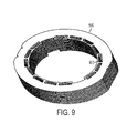
- Fig. 9 illustrates four-pole stator housing 900 having embedded magnets 920.
- the embedded magnets discussed herein are flat magnets, it should be understood that magnets of any shape or form can be employed.
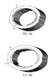
- Figs. 10A and 10B respectively depict a two-pole stator housing 1000 and a four-pole stator housing 1050 having embedded arcuate magnets 1002, 1052.
- a polarity keying feature such as a notch is typically provided in the stator housing.
- the placement of the notch for polarity keying is important for proper alignment of the rotor inside the stator housing as well as proper assembly of the stator housing inside the power tool.
- the notch may, for example, designate the center of North pole or the South pole for power tool that are bias-neutral (such as impact drivers).
- the notch may be off-center with respect to the pole so that the magnetic flux is biased for forward rotor rotation.
- a corresponding projection is provided in the tool housing to fit into the notch when the stator is placed inside the tool housing. This helps ensure proper alignment of the stator within the power tool housing.
- the notch may be removed from the ring using a machining or punching operation, or using another common material removal operation.
- the ring may alternatively be pre-assembled with the notch, for example, via a powder-metal or a similar process.
- the notch in this case may be, for example, 2mm to 4mm in depth.
- the notch may then be filled with plastic material.
- stator housing is a lamination stack instead of a flux ring, as discussed above with respect to the first aspect of the invention, removing the notch becomes more complicated. In this case, the notch would have to be removed from multiple laminations at the end of the stack, but not the other laminations within the stack.
- the laminations are manufactured using a stamping tool configured to stamp an identical layout (e.g., via a stamping die) on all the laminations. Providing the notch on the end of the lamination stack would require a different stamping tool with a different stamping die to be dedicated just to the end laminations with the notch.
- the stator housing lamination stack 1100 may be provided with end cap 1102 having a keying feature 1104 (also referred to as identification feature 1104) for identifying stator polarity keying.
- the keying feature may be, e.g., a notch or a projection, although a notch is preferred.
- the end cap 1102 may be placed at one or both ends of the lamination stack 1100.
- the end caps 1102 may be made of plastic material formed with the notch 1104.
- the plastic end caps 1102 may be attached to the stator housing 1100 via an adhesive or by insertion of projections 1106 into corresponding holes (not shown) in the laminations.
- Figs. 12A - 12C depict an alternative embodiment of the invention.
- the stator lamination stack 1200 is overmolded by an overmold layer 1204.
- the overmold 1204 may be used to securely hold the magnets (in a non-embedded stator housing design) to the inner surface of the stator housing 1200.
- the details of overmolding the inner surface of the stator assembly to secure the magnets are provided in U.S. Pat. Nos. 6,522,042 ; 7,088,024 and 6,983,529 , which are incorporated herein by reference in their entireties.
- the improved overmold 1204 in addition to covering the inner surface of the stator lamination stack 1200, extends beyond the ends of the lamination stack 1204 to laterally and integrally includes two ends caps 1204a and 1204b covering the two ends of the stator lamination stack 1200, as shown in Fig. 12A .
- Fig. 12B shows the same stator lamination stack 1200 as Fig. 12A , but the overmold 1204 depicted transparently to reveal the arrangement of permanent magnets 1202 on the inner surface of the lamination stack 1200 under the overmold 1204.
- Fig. 12C depicts a cross-sectional view of the overmold 1204.
- the overmolded end cap 1204a is provided with a keying feature 1206 (also referred to as identification feature 1206) for identifying the polarity of the stator housing, as shown in Figs. 12A and 12B .
- the keying feature in this embodiment may be a notch recessed in the surface of the end cap 1204a. Alternatively, the notch may be a projection.
- the keying feature 1206, which in this figure is a notch, may be constructed by adding a lip corresponding to the notch at the bottom of the mold tool.
- the notch is formed as the keying feature 1206 in the overmold end cap 1204a along with the holes 1208.
- different mold tools may be needed for molding the keying features (e.g., notches) at different locations.
- the protrusion in the mold tool may be movably adjustable to achieve the desired location of the notch 1206 on the stator assembly in the same mold tool.
- the power tool housing may be provided with a lip corresponding to the keying feature 1104 ( Fig. 11 ) and/or 1206 ( Fig. 12 ).
- the lip fits form-fittingly into the keying feature of the stator housing. This helps ensure proper alignment of the motor within the power tool.
- the keying feature is a projection, a corresponding recess may be provided in the power tool rather than a lip.
- Fig. 12D depicts an exemplary two-pole stator housing 1250 where the magnets are embedded inside magnet pockets (not shown) within North and South poles 1252, 1254.
- the end caps 1256a, 1256b, and the portion 1256 covering the inter-pole spacer may be desirable to overmold only the end caps 1256a, 1256b, and the portion 1256 covering the inter-pole spacer, without overmolding the inner surface of the stator housing over covering the pole magnets.
- the keying feature 1258 is formed in this embodiment in the end cap 1256a.
- the lamination in the lamination stack may be interlocked laminations.
- interlocked laminations are pre-stacked at predetermined lengths, e.g., 16mm, 21mm, or 26mm, when provided by industry suppliers. It is difficult to add or remove laminations from a stack of interlocked laminations.
- loose laminations may be provided. Conventionally loose laminations have been used for the most part in rotor assemblies, where the laminations can press-fitted onto the rotor shaft. Where loose laminations have been used for the stator assembly in the past, they have been welded together at high temperature to form a solid flux ring.
- the stator housing 1200 is made up of a stack of loose laminations overmolded at the two ends by the overmold layer 1204 to be firmly held together.
- the overmold 1204 includes an overmold layer covering the insider surface of the lamination stack, including the magnets 1202 and/or the inner-pole spacers 416, and two overmolded end caps extending laterally from the overmold layer to cover the two ends of the lamination stack 1200.
- the inner overmold layer may cover all or part of the inner-surface of the lamination stack, but it extends from one end of the lamination stack to the other end. The overmold 1204 therefore holds the stack of loose laminations together.
- Fig. 12C provides a cross-sectional view of the stator housing 1200 with the overmold 1204 holding the laminations together.
- the above-discussed embodiment relates to a motor assembly with surface-mounted magnets (i.e., where magnets are not embedded inside magnet pockets of the stator housing), this arrangement may also be applied to a stator housing made of loose laminations and having embedded magnets.
- the resin overmold layer 1256 includes end caps 1256a and 1256b and also covers the area between the North and South poles 1252 and 1254 to connect the end caps 1256a and 1256b.
- the overmold layer 1245 does not cover the poles 1252 and 1254.
- the overmold layer 1245 thus holds the lamination stack of the stator housing 1250 securely together without effecting the magnetic flux of the stator housing 1250.
- the overmold layer may cover an outer surface of the stator housing 1250.
- the overmold layer discussed above may include a resin compound including magnetic material.
- the concept of using an overmold magnetic resin to cover the inside surface of the stator housing in order to improve magnetic flux is discussed in Black & Decker's Application No. 13,112,141, filed May 20, 2011 . This application is incorporated herein by its entirety.
- the improvement according to this embodiment utilizes a magnetic resin compound to cover the inner surface as well as the ends of the lamination stack 1200. This arrangement is advantageous because the nonmagnetic overmold resin does not efficiently carry magnetic flux, but the end cap portion of the overmold resin increases the overall length of the stator assembly.
- the overmold end caps increase the length of the stator by 1.5mm on each end (addition of 3mm to the total length of the stator housing).
- a lesser number of laminations need to be used to make up for the addition of the overmold at the ends of the lamination stack. This of course further reduces the magnetic flux.
- using a magnetic resin compound in the overmold material allows for the total length of the stator housing to remain unchanged without sacrificing magnetic flux of the assembly.
- the magnetism of the overmold at the ends of the lamination stack makes up for the lower number of laminations in the lamination stack.
- the overmold material according to this embodiment may includes a magnetic compound, such as iron powder, ferrite powder, or rare-earth material powder, added to the plastic resin prior to overmolding the lamination stack.
Landscapes
- Engineering & Computer Science (AREA)
- Power Engineering (AREA)
- Iron Core Of Rotating Electric Machines (AREA)
- Permanent Field Magnets Of Synchronous Machinery (AREA)
Abstract
Description
- This application claims the benefit of
U.S. Provisional Application No. 61/579,345, filed on December 22, 2011 - This disclosure relates to arrangement of magnets in the stator of electric motors, particularly for power tools.
- In a brushed DC motor construction, the motor stator magnets must be retained within the motor housing on the inner surface of the stator ring or the stator lamination stack. A lamination stack may include a series of laminations with interlocking features. Typically interlocked laminations are pre-stacked at predetermined lengths, e.g., 16mm, 21mm, or 26mm, when provided by industry suppliers. It is difficult to add or remove laminations from a stack of interlocked laminations. Alternatively, loose laminations may be used to provide more flexibility. Conventionally loose laminations have been used for the most part in rotor assemblies, where the laminations can press-fitted onto the rotor shaft. Where loose laminations have been used for the stator assembly in the past, they have been welded together at high temperature to form a solid flux ring. However, this process is expensive and burdensome. What is needed is a mechanism to utilize loose laminations without the cost associated with the welding operation.
- According to an aspect of the invention, a power tool is provided including a housing, a permanent magnet electric motor in the housing, and an output member coupled to the electric motor. The electric motor includes a stator and a rotor arranged rotatably inside the stator with at least a North pole and a South pole. The stator includes a lamination stack having loose laminations held together via an overmolded resin. The overmolded resin includes a longitudinal overmold layer covering at least a portion of at least one of an inner or outer surfaces of the lamination stack, and two end cap portions extending laterally from the ends of the longitudinal overmold layer to firmly cover ends of the lamination stack.
- According to an embodiment, the stator lamination stack defines at least one magnet pocket at each pole, each magnet pocket being contained within the lamination stack distanced from the inner and outer surfaces of the lamination stack. In an embodiment, the stator further including at least one permanent magnet embedded within each magnet pocket of each pole.
- According to an embodiment, the lamination stack includes inner-pole spacers between the North and the South pole and the longitudinal overmold layer covers the inter-pole spacers. In an embodiment, the inner-pole spacers are recessed with respect to an inner surface of the lamination stack and the longitudinal overmold layer fills in the recessed inner-pole spacers inside the lamination stack. In an embodiment, the inner-pole spacers are recessed with respect to an outer surface of the lamination stack and the longitudinal overmold layer fills in the recessed inner-pole spacers outside the lamination stack.
- According to an embodiment, the longitudinal overmold layer cover substantially all of at least one of the inner or outer surfaces of the stator lamination stack.
- According to an embodiment, the overmold resin layer comprises magnetically-conductive material in at least the end caps.
- The drawings described herein are for illustration purposes only and are not intended to limit the scope of this disclosure in any way.
-
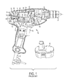
FIG. 1 is side perspective view of a prior art power tool; -
FIG. 2 is cross-sectional view of a stator assembly for a PMDC motor having 3 planar magnet segments; -
FIG. 3 is cross-sectional view of a stator assembly for a PMDC motor having five planar magnets per pole attached to flat sections of a stator housing; -
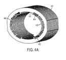
FIG. 4A is a perspective view of a stator housing having magnet pockets for holding magnets, according to an aspect of this disclosure; -
FIG. 4B is a perspective view of a single lamination in the lamination stack of the stator housing ofFIG. 4A , according to an embodiment of the invention; -
FIG. 4C is a cross-sectional view of the stator housing ofFIG. 4A with the permanent magnets embedded in the magnet pockets, according to an embodiment of the invention; -
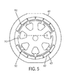
FIG. 5 is a cross-sectional view of a stator housing having air holes between the magnet pockets, according to a further embodiment of the invention; -
FIG. 6A is a perspective view of a stator housing having extended magnet pockets according to another embodiment of the invention; -
FIG. 6B is a cross-sectional view of the stator housing ofFIG. 6A with the permanent magnets embedded in the magnet pockets; -
FIG. 7A is a perspective view of a stator housing having extended magnet pockets according to yet another embodiment of the invention; -
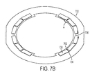
FIG. 7B is a cross-sectional view of the stator housing ofFIG. 7A with the permanent magnets embedded in the magnet pockets; -
FIG. 8 is a cross-sectional view of a stator housing having extended magnet pockets according to yet another embodiment of the invention; -
FIG. 9 is a perspective view of a four-pole stator housing having magnet pockets for holding magnets, according to an embodiment of the invention; -
FIGs. 10A is a perspective view of a two-pole stator housing having magnet pockets for holding arcuate magnets, according to an embodiment of the invention; -
FIGs. 10B is a perspective view of a four-pole stator housing having magnet pockets for holding arcuate magnets, according to an embodiment of the invention; -
FIG. 11 is a perspective view of a stator housing having end a notch at an end cap according to an embodiment of the invention; -
FIG. 12A is a perspective view of a stator housing having a notch in an overmold layer according to an embodiment of the invention; -
FIG. 12B is a perspective view of the stator housing ofFIG. 12A with the overmold layer being shown transparently; -
FIG. 12C is a cross-sectional view of the stator housing ofFIG. 12A ; - FIG. 12D is a perspective view of a stator housing with embedded permanent magnets having a notch in an overmold layer according to an embodiment of the invention; and
- FIG. 12E is a cross-sectional view of the stator housing of FIG. 12D. Referring now to
FIG. 1 , a priorart power tool 10 is shown. Thepower tool 10 includes ahousing 12 which surrounds amotor 14. Anactuation member 16 is coupled with the motor and apower source 18. Thepower source 18 includes either a power cord (AC current) or includes a battery pack 19 (DC current). Themotor 14 is coupled with anoutput member 20 that includes atransmission 22 and achuck 24. Thechuck 24 is operable to retain a tool (not shown). - The motor includes a
stator assembly 30. Thestator assembly 30 includes astator housing 32, a stator lamination stack (or a flux ring) 34 andmagnets 36. Theflux ring 34 is an expandable or split flux ring. Anarmature 40 includes ashaft 42, arotor 44 and acommutator 50 coupled with theshaft 42. Therotor 44 includeslaminations 46 andwindings 48. Themotor 14 also includesend plates End plate 52 includes afront bearing 56 which supports one end of ashaft 42. Theshaft 42 is coupled with apinion 60 that is part of theoutput member 20.Brushes commutator 50. Arear bearing 70 is also coupled with theend plate 54 to balance rotation of theshaft 42. - The
power tool 10 is illustrated as a drill, however, any type of power tool may be used in accordance with this invention. Thepower tool 10 includes ahousing 12 which surrounds amotor 14. Anactivation member 16 is coupled with the motor and apower source 18. Thepower source 18 includes either a power cord (AC current) or includes a battery (DC current) (not shown). Themotor 14 is coupled with anoutput member 20 that includes atransmission 22 and achuck 24. Thechuck 24 is operable to retain a tool (not shown). - The
designation 34 illustrated inFig. 1 may be a flux ring, which is made of solid metal and includes a cylindrical inner surface on which thepermanent magnets 36 are mounted. Alternatively, and in accordance with embodiments of the invention described herein,designation 34 may be a stator lamination stack made of a series of flat laminations attached to one another. The laminations in thelamination stack 34 may be interlocked. Typically interlocked laminations are provided from an industry supplier with predetermined lengths, e.g., 16mm, 21mm, or 26mm. Alternatively, the laminations may be loose, in which case they are typically welded together at high temperature to form a solid flux ring. - According to the embodiment shown in
Fig. 1 , a stator housing (or frame) 32 is provided in addition to the lamination stack orflux ring 34. However, it should be understood that the flux ring or thelamination stack 34 may be anchored directly in the tool housing without the use of anadditional stator housing 32 in what is commonly referred to as frameless motors. In that case, the flux ring or thelamination stack 34 itself acts as the stator housing. - According to an embodiment, the magnets may be arcuate or flat magnets arranged on the inner surface of the
lamination stack 34. As described inU.S. Pat. Nos. 6,522,042 ;7,088,024 and6,983,529 , which are incorporated herein by reference in their entireties, the magnets may anchored to thelamination stack 34 by an overmolding process. -
FIG. 2 depicts a cross-sectional view showing anexemplary stator assembly 200 for a PMDC having astator housing 202. Eachpole 208 in thestator housing 202 includes twopartial poles 206. There are 3flat magnets 204 perpartial pole 206. It should be understood that eachpole 208 could be formed by three or more sets of two or moreflat magnets 204. It should also be understood that the PMDC motor could have a plurality of north andsouth poles 208. Although thestator assembly 200 inFig. 2 appears to be a flux can, the same arrangement may be utilized in a lamination stack. -
FIG. 3 shows anexemplary stator assembly 300 for a PMDC motor that includes five smallerflat magnets 302 for each of the poles 304 (north and south poles).Stator housing 306 illustratively is a lamination stack having flat portions 308 (only one of which is identified inFIG. 3 with the reference number 308) in itsinner surface 310 to which theflat magnets 302 are mounted.Outer surface 312 of thestator housing 306 illustratively is arcuate except for twoopposed flats 314 centrally located over the centerflat magnet 302 of theflat magnets 302 for thepoles 304. These twoopposed flats 314 extend across the respective centerflat magnet 302 of therespective pole 304 and partially across each of the twoflat magnets 302 adjacent opposed sides of each centerflat magnet 302. As such, the thickness of thestator housing 306 is thinner adjacent the centerflat magnets 302 of eachpole 304 and thicker adjacent the outerflat magnets 302 of eachpole 304. This provides the increased flux density at the outerflat magnets 302 where it is most needed and yet allows for reduction in the thickness of steel (saving both weight and material) at the centerflat magnets 302 where having such increased flux density is less important. - It should be noted that the two stator assemblies discussed above are merely for illustration purposes and are not intended to narrow the scope of this disclosure in any way. Embodiments of the invention discussed hereinafter can be applied to any stator assembly with permanent magnets mounted therein.
- Typically in motor assemblies described above, a physical (i.e., mechanical) air gap is provided between the outer surface of the rotor assembly and the inner surface of the stator assembly. This air gap accounts for tolerances, i.e., the permissible limit of variations in the dimension or size, associated with the stator and rotor assemblies. In a typical stator assembly (for example, those shown in
Figs. 2 and 3 ), the stator lamination stack may, for example, have a tolerance of approximately ± 0.1 mm due to minor variations in the radius of its inner periphery. The magnets may also have tolerances of, for example, approximately ± 0.05 mm due to small variations in their heights and/or widths. In addition, as previously discussed, the permanent magnets in the stator assembly may be fixed to the stator housing via an adhesive or overmolded to the stator housing by a plastic resin. The adhesive material and/or the overmolded resin material are difficult to apply uniformly and may therefore further increase the overall tolerance of the stator assembly by, for example, approximately ± 0.05 mm to ± 0.15 mm. Thus, in the stator assemblies shown inFigs. 2 and 3 , the overall tolerance level of ± 0.2 mm or more is typical. It should be noted that the rotor assembly, albeit not discussed herein, has its own tolerance levels that should be taken into account as well. - While the mechanical air gap between the rotor and stator assemblies is needed to account for their respective tolerances, air has a relatively low magnetic permeability and reduces the overall flux of the stator assembly applied to the rotor assembly. In addition, in motors where magnets are overmolded, the overmoded resin further increases the distance between the magnets and the rotor. The overmolded resin therefore further affects the overall flux of the stator assembly applied to the rotor. In an exemplary conventional power tool motor assembly with overmolded magnets, the overall distance taken up by air gap and the overmold layer combined was measured to be between 0.93 mm to 1.45 mm. This distance, which is known as the "magnetic air gap," refers to the space between the magnets and the rotor taken up by non-magnetically-conductive material such as air, adhesive, resin, etc.
- According to an aspect of the invention, In order to minimize the magnetic air gap between the magnets and the rotor assmbly, an embedded magnet design is provided. As shown in the perspective view of
Fig. 4A , a stator housing 400 (in this case in the form of a lamination stack) is provided withmagnet pockets 402 to securely hold and enclose the permanent magnets. In this example, thestator housing 400 is a two-pole stator in which each pole includes sixmagnet pockets 402 for holding permanent magnets. As discussed further below, this embedded design reduces the air gap between thestator housing 400 and the rotor housing (not shown) to increase the flux density. -
Fig. 4B shows asingle lamination 410 of thelamination stack 400. Thelamination 410 includespockets 412. Thelamination stack 400 includes multiple identically-shapedlaminations 410 arranged in parallel. Thepockets 412 of alllaminations 410 align to form magnet pockets 402 for holding the magnets. -
Fig. 4C shows a cross-sectional view of the statorhousing lamination stack 400 with themagnets 420 embedded therein. Themagnets 420 fit form-fittingly inside the magnet pockets 402 of thelamination stack 400 to securely hold the magnets in place without using any adhesive and/or overmold resin. In some embodiments, some form of adhesive may be provided to better secure themagnets 420 inside the magnet pockets 402; however, the use of adhesive in such instances would be minimal. - In the embedded magnet design according to the present embodiment of the invention, the magnetic flux applied from the stator assembly to the rotor assembly is improved for several reasons. First, in this design, a magnetically-
conductive section 404 of thelamination stack 400 separates themagnets 420 from the rotor assembly. Unlike air, the magnetically-conductive section 404 is highly permeable and therefore improves the overall magnetic flux of thestator assembly 400. Also, the embedded design according to this embodiment eliminates or minimizes the use of any adhesive or overmold to secure themagnets 420 to thestator assembly 400. This further removes another barrier from the path of the magnetic flux. Moreover, since the tolerances associated with themagnets 420 and the adhesive discussed above are effectively eliminated, the total tolerance of the stator assembly can be drastically reduced. In an exemplary embodiment, the total tolerance level for the stator assembly may be reduced from ±0.2 mm for comparable conventional designs to ±0.1 mm or less for the embedded design. The lower tolerance allows for a smaller mechanical air gap between the rotor assembly and the stator assembly. The reduction in the mechanical air gap in turn, combined with the elimination or reduction in the adhesive and/or overmold layer between the magnets and the rotor assembly, substantially decreases the length of the overall magnetic air gap, thus improving the overall magnetic flux applied from the stator assembly to the rotor assembly. - It was found by the inventors that the embedded magnet design described herein, allows for substantial reduction in the magnetic air gap. According to an embodiment, the total magnetic air gap between the stator lamination stack and the rotor may be reduced from 0.93 to 1.45 mm in conventional non-embedded (i.e., surface-mounted) magnet motors to approximately 0.70 mm or less in the embedded design. In one embodiment, the total magnetic flux / magnet volume (k-Max/mm3), as measured from the rotor assembly, is increased by approximately 49% to 56% in the embedded design as compared to conventional non-embedded (i.e., surface-mounted) magnet motors, given the same size/grade magnets. Accordingly, in order to obtain comparable power output levels as conventional surface-mounted magnet motors, smaller magnets may be utilized in the stator assembly. It was found by the inventors that to obtain similar output levels as the conventional surface-mounted magnet motors, the embedded magnet design according to this embodiment reduced the total amount of magnetic material used by 30% to 40%. This may translate to substantial cost-saving given the high cost of rare earth material.
- It should be noted that the embedded design according to this embodiment provides other advantages in addition to improvements in the magnetic flux density. For example, since the embedded design provides a
smoother surface 406 than conventional stator assemblies, the cogging effect of the stator assemblies associated with the unevenness of the magnets in conventional designs is reduced. Moreover, the dimensional flexibility of the laminated magnet pockets 402 makes it possible to mix and match different grade magnets with minor variations in thickness or width as long as the magnets fit inside the magnet pockets 402. - Furthermore, as described in Black & Decker's Application No.
13/112,136, filed May 20, 2011 - It should be noted that while the exemplary stator housing shown in these figures is a lamination stack, the present design is not limited to a lamination stack and the teachings of this disclosure may be applied to a flux ring or other types of stator assemblies as well.
- A further improvement to the embodiment of the invention described above is discussed herein. According to an embodiment, while the
conductive wall 404 between themagnets 420 and the rotor assembly increases the magnetic flux density at the rotor, the magnetically-conductive spacers 408 conversely allow for some unwanted leakage of the magnetic flux. Accordingly, in an embodiment of the invention as shown inFig. 5 ,air holes 502 may be introduced between adjacent magnet pockets 402 of thestator assembly 400. The air holes 502 may be configured to minimize leakage of the flux path between themagnets 420. Similarly, the magnet pockets 402 may be shaped (particularly around the edges of the pockets 402) to minimize the conductive path through the magnetically-conductive spacers 408 between theadjacent magnets 420. For example, the outer edges of magnet pockets 402 may be rounded or otherwise extended to create some air pocket between themagnet 420 and the magnetically-conductive spacers 408, thereby minimizing the width of thespacers 408. - Referring back to
Fig. 4C , each pole of thestator housing 400 is defined byedges 418 on thesurface 406.Inter-pole spacers 416 are provided on thesurface 406 between therespective edges 418 of the poles. Theedges 418 and theinter-pole spacers 416 may be shaped to optimize the flux path from themagnets 420 in each pole towards the rotor assembly (not shown). - According to an alternative and/or further embodiment, as shown in
Figs. 6A and6B , a stator housing 600 (in this case lamination stack 600) may be provided withmagnet pockets 602 configured to accommodated twomagnets 620. In this embodiment, eachmagnet pocket 602 includes two rectangular-shaped portions connected at an angle θ° with each portion holding amagnet 620, such that themagnets 620 housed in themagnet pocket 602 are generally perpendicular to the outer surface of the rotor assembly (not shown). In this example, thestator housing 600 is a two-pole stator, where each pole includes three magnet pockets 602. While adjacent magnet pockets 602 are separated by aconductive spacer 606, themagnets 620 within eachmagnet pocket 602 are separated via anair pocket 604 formed at the connection points of the rectangular-shaped portions. Similarly to the air holes 502 inFig. 5 , theair pockets 604 in this embodiment help increase the magnetic flux applied to the rotor by reducing leakage of the flux path. -
Figs. 7A and7B illustrate yet another embodiment, in which a stator housing (in this case lamination stack 700) is a two-pole stator, with each pole having twomagnet pocket 702 and eachmagnet pocket 702 housing three embeddedmagnets 720. In this embodiment, eachmagnet pocket 702 is made up of three rectangular-shaped portions connected side-by-side at an angle θ° such that themagnets 720 housed in themagnet pocket 702 are generally perpendicular to the outer surface of the rotor assembly (not shown). The two adjacent magnet pockets 702 within each pole are separated by aconductive spacer 706. Themagnets 720 within eachmagnet pocket 702 are separated viaair gaps 704, which improve the magnetic flux at applied to the rotor even further. -
Fig. 8 illustrates a cross-sectional view of yet another embodiment, in which thestator housing 800 employs no conductive spacers between themagnets 820 within each pole. In this embodiment, each pole includes oneextended magnet pocket 802 which houses sixmagnet 820. Themagnets 820 within eachmagnet pocket 802 are separated byair gaps 804. It was found by the inventors that this arrangement increases the effective flux measured at the plane AB of therotor assembly 830 by about 8% (compared to the arrangement shown inFig. 4A ). - It should be understood that while the exemplary embodiments above were discussed with references to two-pole stators, the embedded magnet concept of this disclosure can be applied to a stator with any number of poles.
Fig. 9 , for example, illustrates four-pole stator housing 900 having embeddedmagnets 920. Furthermore, while the embedded magnets discussed herein are flat magnets, it should be understood that magnets of any shape or form can be employed.Figs. 10A and 10B respectively depict a two-pole stator housing 1000 and a four-pole stator housing 1050 having embeddedarcuate magnets - A second aspect of the invention is discussed herein. In a stator assembly, in order to identify the polarity of the stator, a polarity keying feature such as a notch is typically provided in the stator housing. The placement of the notch for polarity keying is important for proper alignment of the rotor inside the stator housing as well as proper assembly of the stator housing inside the power tool. The notch may, for example, designate the center of North pole or the South pole for power tool that are bias-neutral (such as impact drivers). In other products that are forward-biased (i.e., the motor is more likely to move in the forward direction than in the reverse direction, such as drills), the notch may be off-center with respect to the pole so that the magnetic flux is biased for forward rotor rotation. Typically, a corresponding projection is provided in the tool housing to fit into the notch when the stator is placed inside the tool housing. This helps ensure proper alignment of the stator within the power tool housing.
- If the stator housing is a flux ring, the notch may be removed from the ring using a machining or punching operation, or using another common material removal operation. The ring may alternatively be pre-assembled with the notch, for example, via a powder-metal or a similar process. The notch in this case may be, for example, 2mm to 4mm in depth. The notch may then be filled with plastic material.
- If the stator housing is a lamination stack instead of a flux ring, as discussed above with respect to the first aspect of the invention, removing the notch becomes more complicated. In this case, the notch would have to be removed from multiple laminations at the end of the stack, but not the other laminations within the stack. The laminations are manufactured using a stamping tool configured to stamp an identical layout (e.g., via a stamping die) on all the laminations. Providing the notch on the end of the lamination stack would require a different stamping tool with a different stamping die to be dedicated just to the end laminations with the notch. Also, even though the more advanced stamping tools are configurable to add or remove features from a layout, adding and removing the notch feature for the notched laminations is time consuming and complicates the process. Furthermore, as previously discussed, it may be necessary to place the notch in different locations based on the product, i.e., for forward-bias keying for tools such as drills. Thus, different sets of end laminations with the notches at different locations may need to be stamped. The notched laminations must then be matched up with the appropriate lamination stack. This entire process is expensive and burdensome.
- Accordingly, in an embodiment of the invention shown in
Fig. 11 , the statorhousing lamination stack 1100 may be provided withend cap 1102 having a keying feature 1104 (also referred to as identification feature 1104) for identifying stator polarity keying. The keying feature may be, e.g., a notch or a projection, although a notch is preferred. Theend cap 1102 may be placed at one or both ends of thelamination stack 1100. The end caps 1102 may be made of plastic material formed with thenotch 1104. Theplastic end caps 1102 may be attached to thestator housing 1100 via an adhesive or by insertion ofprojections 1106 into corresponding holes (not shown) in the laminations. -
Figs. 12A - 12C depict an alternative embodiment of the invention. In this embodiment, thestator lamination stack 1200 is overmolded by anovermold layer 1204. Theovermold 1204 may be used to securely hold the magnets (in a non-embedded stator housing design) to the inner surface of thestator housing 1200. The details of overmolding the inner surface of the stator assembly to secure the magnets are provided inU.S. Pat. Nos. 6,522,042 ;7,088,024 and6,983,529 , which are incorporated herein by reference in their entireties. According to this embodiment, the improved overmold 1204, in addition to covering the inner surface of thestator lamination stack 1200, extends beyond the ends of thelamination stack 1204 to laterally and integrally includes two endscaps stator lamination stack 1200, as shown inFig. 12A .Fig. 12B shows the samestator lamination stack 1200 asFig. 12A , but theovermold 1204 depicted transparently to reveal the arrangement ofpermanent magnets 1202 on the inner surface of thelamination stack 1200 under theovermold 1204.Fig. 12C depicts a cross-sectional view of theovermold 1204. - According to this embodiment, the
overmolded end cap 1204a is provided with a keying feature 1206 (also referred to as identification feature 1206) for identifying the polarity of the stator housing, as shown inFigs. 12A and12B . The keying feature in this embodiment may be a notch recessed in the surface of theend cap 1204a. Alternatively, the notch may be a projection. Thekeying feature 1206, which in this figure is a notch, may be constructed by adding a lip corresponding to the notch at the bottom of the mold tool. When the molding material flows under thestator housing 1200 in the molding machine (thestator housing 1200 is held up in the mold tool by a plurality of legs corresponding to the holes 1208), the notch is formed as thekeying feature 1206 in theovermold end cap 1204a along with theholes 1208. - According to an embodiment, different mold tools may be needed for molding the keying features (e.g., notches) at different locations. However, since mold tools are far cheaper than lamination tools, the overall cost of manufacturing is drastically reduced. According to another embodiment, the protrusion in the mold tool may be movably adjustable to achieve the desired location of the
notch 1206 on the stator assembly in the same mold tool. - According to an embodiment of the invention, the power tool housing may be provided with a lip corresponding to the keying feature 1104 (
Fig. 11 ) and/or 1206 (Fig. 12 ). When the motor is placed in the power tool during the assembly process, the lip fits form-fittingly into the keying feature of the stator housing. This helps ensure proper alignment of the motor within the power tool. It should be understood that if the keying feature is a projection, a corresponding recess may be provided in the power tool rather than a lip. - It should be understood that while this arrangement is discussed with respect to a conventional motor assembly with surface-mounted magnets (i.e., where magnets are not embedded inside magnet pockets of the stator housing), the overmolded end caps of this embodiment including the
keying feature 1206 may be applied to a stator housing having embedded magnets (i.e., as discussed with reference toFigs. 4A -10B ). Fig. 12D depicts an exemplary two-pole stator housing 1250 where the magnets are embedded inside magnet pockets (not shown) within North and South poles 1252, 1254. In this embodiment, it may be desirable to overmold only the end caps 1256a, 1256b, and the portion 1256 covering the inter-pole spacer, without overmolding the inner surface of the stator housing over covering the pole magnets. Alternatively, it is possible to overmold the outer surface of the stator housing 1250. The keying feature 1258 is formed in this embodiment in the end cap 1256a. - Another aspect of the invention is discussed herein still with reference to
Figs. 12A-12C . As previously discussed, the lamination in the lamination stack may be interlocked laminations. Typically interlocked laminations are pre-stacked at predetermined lengths, e.g., 16mm, 21mm, or 26mm, when provided by industry suppliers. It is difficult to add or remove laminations from a stack of interlocked laminations. Alternatively, loose laminations may be provided. Conventionally loose laminations have been used for the most part in rotor assemblies, where the laminations can press-fitted onto the rotor shaft. Where loose laminations have been used for the stator assembly in the past, they have been welded together at high temperature to form a solid flux ring. - According to an embodiment of the invention, as shown in
Figs. 12A-12C , thestator housing 1200 is made up of a stack of loose laminations overmolded at the two ends by theovermold layer 1204 to be firmly held together. Theovermold 1204 includes an overmold layer covering the insider surface of the lamination stack, including themagnets 1202 and/or the inner-pole spacers 416, and two overmolded end caps extending laterally from the overmold layer to cover the two ends of thelamination stack 1200. The inner overmold layer may cover all or part of the inner-surface of the lamination stack, but it extends from one end of the lamination stack to the other end. Theovermold 1204 therefore holds the stack of loose laminations together. Overmolding the ends of thelamination stack 1200 also provides high impact resistance and thus further improves the structural integrity of the stator assembly.Fig. 12C provides a cross-sectional view of thestator housing 1200 with theovermold 1204 holding the laminations together. - Although the above-discussed embodiment relates to a motor assembly with surface-mounted magnets (i.e., where magnets are not embedded inside magnet pockets of the stator housing), this arrangement may also be applied to a stator housing made of loose laminations and having embedded magnets. Specifically, as shown in Figs. 12D and 12E, the resin overmold layer 1256 includes end caps 1256a and 1256b and also covers the area between the North and South poles 1252 and 1254 to connect the end caps 1256a and 1256b. However, the overmold layer 1245 does not cover the poles 1252 and 1254. The overmold layer 1245 thus holds the lamination stack of the stator housing 1250 securely together without effecting the magnetic flux of the stator housing 1250. In an alternatively embodiment, the overmold layer may cover an outer surface of the stator housing 1250.
- According to a further embodiment of the invention, the overmold layer discussed above may include a resin compound including magnetic material. The concept of using an overmold magnetic resin to cover the inside surface of the stator housing in order to improve magnetic flux is discussed in Black & Decker's Application No.
13,112,141, filed May 20, 2011 lamination stack 1200. This arrangement is advantageous because the nonmagnetic overmold resin does not efficiently carry magnetic flux, but the end cap portion of the overmold resin increases the overall length of the stator assembly. In an exemplary stator assembly, the overmold end caps increase the length of the stator by 1.5mm on each end (addition of 3mm to the total length of the stator housing). Thus, if it is desired to keep the total length of the stator housing unchanged, a lesser number of laminations need to be used to make up for the addition of the overmold at the ends of the lamination stack. This of course further reduces the magnetic flux. According to this embodiment of the invention, using a magnetic resin compound in the overmold material allows for the total length of the stator housing to remain unchanged without sacrificing magnetic flux of the assembly. In other words, the magnetism of the overmold at the ends of the lamination stack makes up for the lower number of laminations in the lamination stack. The overmold material according to this embodiment may includes a magnetic compound, such as iron powder, ferrite powder, or rare-earth material powder, added to the plastic resin prior to overmolding the lamination stack. - The description of the invention is merely exemplary in nature and, thus, variations that do not depart from the gist of the invention are intended to be within the scope of the invention. Such variations are not to be regarded as a departure from the scope of the invention.
Claims (14)
- A power tool, comprising:a housing;a permanent magnet electric motor in the housing, the electric motor including a rotor and a stator with at least a North pole and a South pole, the stator comprising a lamination stack having a plurality of loose laminations, the loose laminations being held together via an overmolded resin, the overmolded resin comprising a longitudinal overmold layer covering at least a portion of at least one of an inner or outer surfaces of the lamination stack, and two end cap portions extending laterally from the ends of the longitudinal overmold layer to firmly cover ends of the lamination stack; andan output member coupled to the electric motor.
- The power tool of claim 1, wherein the stator lamination stack defines at least one magnet pocket at each pole, each magnet pocket being contained within the lamination stack distanced from the inner and outer surfaces of the lamination stack, the stator further including at least one permanent magnet embedded within each magnet pocket of each pole.
- The power tool of claim 1, wherein the lamination stack comprises inner-pole spacers between the North and the South pole and the longitudinal overmold layer covers the inter-pole spacers.
- The power tool of claim 3, wherein the inner-pole spacers are recessed with respect to an inner surface of the lamination stack and the longitudinal overmold layer fills in the recessed inner-pole spacers inside the lamination stack.
- The power tool of claim 3, wherein the inner-pole spacers are recessed with respect to an outer surface of the lamination stack and the longitudinal overmold layer fills in the recessed inner-pole spacers outside the lamination stack.
- The power tool of claim 1, wherein the longitudinal overmold layer cover substantially all of at least one of the inner or outer surfaces of the stator lamination stack.
- The power tool of claim 1, wherein the overmold resin layer comprises magnetically-conductive material in at least the end caps.
- A permanent magnet electric motor comprising:a stator with at least a North pole and a South pole, the stator comprising a lamination stack having a plurality of loose laminations, the loose laminations being held together via an overmolded resin, the overmolded resin comprising a longitudinal overmold layer covering at least a portion of at least one of an inner or outer surfaces of the lamination stack, and two end cap portions extending laterally from the ends of the longitudinal overmold layer to firmly cover ends of the lamination stack; anda rotor arranged rotatably inside the stator.
- The motor of claim 8, wherein the stator lamination stack defines at least one magnet pocket at each pole, each magnet pocket being contained within the lamination stack distanced from the inner and outer surfaces of the lamination stack, the stator further including at least one permanent magnet embedded within each magnet pocket of each pole.
- The motor of claim 8, wherein the lamination stack comprises inner-pole spacers between the North and the South pole and the longitudinal overmold layer covers the inter-pole spacers.
- The motor of claim 10, wherein the inner-pole spacers are recessed with respect to an inner surface of the lamination stack and the longitudinal overmold layer fills in the recessed inner-pole spacers inside the lamination stack.
- The motor of claim 10, wherein the inner-pole spacers are recessed with respect to an outer surface of the lamination stack and the longitudinal overmold layer fills in the recessed inner-pole spacers outside the lamination stack.
- The motor of claim 8, wherein the longitudinal overmold layer cover substantially all of at least one of the inner or outer surfaces of the stator lamination stack.
- The motor of claim 8, wherein the overmold resin layer comprises magnetically-conductive material in at least the end caps.
Applications Claiming Priority (1)
| Application Number | Priority Date | Filing Date | Title |
|---|---|---|---|
| US201161579345P | 2011-12-22 | 2011-12-22 |
Publications (3)
| Publication Number | Publication Date |
|---|---|
| EP2608369A2 true EP2608369A2 (en) | 2013-06-26 |
| EP2608369A3 EP2608369A3 (en) | 2017-08-09 |
| EP2608369B1 EP2608369B1 (en) | 2022-03-23 |
Family
ID=47519890
Family Applications (3)
| Application Number | Title | Priority Date | Filing Date |
|---|---|---|---|
| EP12198341.5A Withdrawn EP2608368A3 (en) | 2011-12-22 | 2012-12-20 | Stator assembly having end cap with polarity keying feature for a power tool |
| EP12198615.2A Active EP2608369B1 (en) | 2011-12-22 | 2012-12-20 | Overmolded stator assembly lamination stack for a power tool |
| EP12198351.4A Withdrawn EP2608361A3 (en) | 2011-12-22 | 2012-12-20 | Stator assembly having embedded magnets for a power tool |
Family Applications Before (1)
| Application Number | Title | Priority Date | Filing Date |
|---|---|---|---|
| EP12198341.5A Withdrawn EP2608368A3 (en) | 2011-12-22 | 2012-12-20 | Stator assembly having end cap with polarity keying feature for a power tool |
Family Applications After (1)
| Application Number | Title | Priority Date | Filing Date |
|---|---|---|---|
| EP12198351.4A Withdrawn EP2608361A3 (en) | 2011-12-22 | 2012-12-20 | Stator assembly having embedded magnets for a power tool |
Country Status (2)
| Country | Link |
|---|---|
| US (3) | US20130162068A1 (en) |
| EP (3) | EP2608368A3 (en) |
Cited By (1)
| Publication number | Priority date | Publication date | Assignee | Title |
|---|---|---|---|---|
| US9837877B2 (en) | 2014-05-09 | 2017-12-05 | Makita Corporation | Electric power tool |
Families Citing this family (3)
| Publication number | Priority date | Publication date | Assignee | Title |
|---|---|---|---|---|
| US20130162068A1 (en) * | 2011-12-22 | 2013-06-27 | Black & Decker Inc. | Overmolded stator assembly lamination stack for a power tool |
| US10523072B2 (en) * | 2016-06-15 | 2019-12-31 | Ford Global Technologies, Llc | Electric machine rotor |
| CN110829711B (en) * | 2019-10-30 | 2020-11-10 | 北京化工大学 | Radial excitation electromagnetic slip ring automatic balancing device |
Citations (3)
| Publication number | Priority date | Publication date | Assignee | Title |
|---|---|---|---|---|
| US6522042B1 (en) | 2000-01-27 | 2003-02-18 | Black & Decker Inc. | Anchoring system for injection molded magnets on a flux ring or motor housing |
| US6983529B2 (en) | 2001-02-23 | 2006-01-10 | Black & Decker Inc. | Stator assembly with an overmolding that secures magnets to a flux ring and the flux ring to a stator housing |
| US7088024B2 (en) | 2001-02-23 | 2006-08-08 | Black & Decker Inc. | Field assembly for a motor and method of making same |
Family Cites Families (38)
| Publication number | Priority date | Publication date | Assignee | Title |
|---|---|---|---|---|
| US1480312A (en) * | 1922-07-26 | 1924-01-08 | Electric Controller & Mfg Co | Method of making stators |
| USRE26788E (en) * | 1969-01-13 | 1970-02-10 | Motor stator stack op bonded laminations with less bonding material at bolt hole regions | |
| US3829720A (en) * | 1970-07-07 | 1974-08-13 | Dynamics Corp America | Motor stator |
| US3768152A (en) * | 1972-01-21 | 1973-10-30 | Dynamics Corp America | Method of making a motor stator |
| US3821846A (en) * | 1973-01-10 | 1974-07-02 | Smith Corp A | Method of manufacturing a motor stator assembly |
| JPS54167311U (en) * | 1978-05-17 | 1979-11-26 | ||
| US4485126A (en) * | 1983-12-21 | 1984-11-27 | General Electric Company | Method of treating winding means of dynamoelectric machine core |
| US4559698A (en) * | 1983-12-21 | 1985-12-24 | General Electric Company | Method of treating a loose wound core, method of fabricating a loose wound core, and method of operating apparatus |
| US4845837A (en) * | 1986-10-06 | 1989-07-11 | Emerson Electric Co. | Method of making permanent magnet assembly |
| JPH07312852A (en) * | 1994-05-13 | 1995-11-28 | Yaskawa Electric Corp | Method of manufacturing permanent magnet rotor |
| US5694268A (en) * | 1995-02-10 | 1997-12-02 | Seagate Technology, Inc. | Spindle motor having overmolded stator |
| US5920139A (en) * | 1996-03-31 | 1999-07-06 | Sanyo Electric Co. Ltd. | Magnet motor stator |
| US6075304A (en) * | 1997-04-30 | 2000-06-13 | Alon Co., Ltd | Stator with molded encasement for small motors and manufacturing process therefor |
| JPH10322944A (en) * | 1997-05-19 | 1998-12-04 | Minebea Co Ltd | Motor structure and manufacturing method thereof |
| JPH1189130A (en) * | 1997-09-08 | 1999-03-30 | Minebea Co Ltd | Motor construction |
| JP3462058B2 (en) * | 1997-11-07 | 2003-11-05 | ミネベア株式会社 | Motor structure |
| US6211587B1 (en) * | 1998-11-12 | 2001-04-03 | Hitachi, Ltd. | Electric rotating machine |
| US6150747A (en) * | 1999-05-04 | 2000-11-21 | Electric Boat Corporation | Composite stator and rotor for an electric motor |
| MXPA03007578A (en) * | 2001-02-23 | 2003-12-04 | Black & Decker Inc | Field assembly for a motor and method of making same. |
| US7036207B2 (en) * | 2001-03-02 | 2006-05-02 | Encap Motor Corporation | Stator assembly made from a plurality of toroidal core segments and motor using same |
| US6777842B2 (en) * | 2001-12-28 | 2004-08-17 | Emerson Electric Co. | Doubly salient machine with permanent magnets in stator teeth |
| US6724114B2 (en) * | 2001-12-28 | 2004-04-20 | Emerson Electric Co. | Doubly salient machine with angled permanent magnets in stator teeth |
| JP2003230234A (en) * | 2002-01-28 | 2003-08-15 | Onsei Kigyo Kofun Yugenkoshi | Permanent-magnet type direct-current brush motor |
| JP3932177B2 (en) * | 2002-05-24 | 2007-06-20 | 株式会社ジェイテクト | Motor manufacturing equipment |
| JP2005261136A (en) * | 2004-03-12 | 2005-09-22 | Koyo Seiko Co Ltd | Electric motor and electric power steering device |
| US7105976B2 (en) * | 2004-10-04 | 2006-09-12 | Emerson Electric Co. | Electric machines and methods related to assembling electric machines |
| JP2007068310A (en) * | 2005-08-30 | 2007-03-15 | Aisin Seiki Co Ltd | Laminated winding core of rotating machine |
| DE202005013840U1 (en) * | 2005-09-01 | 2005-11-03 | CHI HUA FITNESS CO., LTD., Yangmei | Magnetic pole for a permanent magnet dc motor uses combination of rare earth stiff magnets and pole shoes and rotor with projecting spiral sections |
| US7436096B2 (en) * | 2005-10-31 | 2008-10-14 | Caterpillar Inc. | Rotor having permanent magnets and axialy-extending channels |
| US8008824B2 (en) * | 2006-02-01 | 2011-08-30 | Brose Fahrzeugteile Gmbh & Co. Kommanditgesellschaft, Wuerzburg | Electric motor |
| US20110278966A1 (en) * | 2006-10-13 | 2011-11-17 | Black & Decker Inc. | Motor With Overmolded Permanent Magnets |
| US20110298313A1 (en) * | 2006-10-13 | 2011-12-08 | Black & Decker Inc. | Motor With Permanent Magnets and Method of Manufacturing Power Tool With Same |
| US8823234B2 (en) * | 2006-10-13 | 2014-09-02 | Black & Decker Inc. | Motor with permanent magnets having essentially the same inner and outer radius; and method of manufacturing a motor stator housing with permanent magnets |
| WO2008048486A1 (en) * | 2006-10-13 | 2008-04-24 | Black & Decker Inc. | Anchoring system for a stator housing assembly having an overmolding; power tool with same |
| GB2454171B (en) * | 2007-10-29 | 2012-05-23 | Technelec Ltd | Reluctance machines with permanent magnets integrated into the stator |
| US8283841B2 (en) * | 2010-06-23 | 2012-10-09 | Lin Engineering | Motor end cap with interference fit |
| DE102011003831A1 (en) * | 2011-02-09 | 2012-08-09 | Robert Bosch Gmbh | Stator for e.g. fractional horse-power motor, has stator laminated core assembled from stator teeth and stator frame and provided with stator outer periphery and stator inner periphery, where stator winding is attached on stator teeth |
| US20130162068A1 (en) * | 2011-12-22 | 2013-06-27 | Black & Decker Inc. | Overmolded stator assembly lamination stack for a power tool |
-
2012
- 2012-12-18 US US13/718,891 patent/US20130162068A1/en not_active Abandoned
- 2012-12-18 US US13/718,501 patent/US20130162067A1/en not_active Abandoned
- 2012-12-18 US US13/718,791 patent/US20130162062A1/en not_active Abandoned
- 2012-12-20 EP EP12198341.5A patent/EP2608368A3/en not_active Withdrawn
- 2012-12-20 EP EP12198615.2A patent/EP2608369B1/en active Active
- 2012-12-20 EP EP12198351.4A patent/EP2608361A3/en not_active Withdrawn
Patent Citations (3)
| Publication number | Priority date | Publication date | Assignee | Title |
|---|---|---|---|---|
| US6522042B1 (en) | 2000-01-27 | 2003-02-18 | Black & Decker Inc. | Anchoring system for injection molded magnets on a flux ring or motor housing |
| US6983529B2 (en) | 2001-02-23 | 2006-01-10 | Black & Decker Inc. | Stator assembly with an overmolding that secures magnets to a flux ring and the flux ring to a stator housing |
| US7088024B2 (en) | 2001-02-23 | 2006-08-08 | Black & Decker Inc. | Field assembly for a motor and method of making same |
Cited By (1)
| Publication number | Priority date | Publication date | Assignee | Title |
|---|---|---|---|---|
| US9837877B2 (en) | 2014-05-09 | 2017-12-05 | Makita Corporation | Electric power tool |
Also Published As
| Publication number | Publication date |
|---|---|
| US20130162067A1 (en) | 2013-06-27 |
| EP2608368A3 (en) | 2017-08-16 |
| US20130162062A1 (en) | 2013-06-27 |
| EP2608361A2 (en) | 2013-06-26 |
| EP2608368A2 (en) | 2013-06-26 |
| EP2608369B1 (en) | 2022-03-23 |
| EP2608369A3 (en) | 2017-08-09 |
| US20130162068A1 (en) | 2013-06-27 |
| EP2608361A3 (en) | 2017-08-09 |
Similar Documents
| Publication | Publication Date | Title |
|---|---|---|
| EP2076954B1 (en) | Motor with permanent magnets and method of manufacturing; power tool with same | |
| CN103597714B (en) | The manufacture method of rotor for dynamo-electric machine, electric rotating machine and rotor for dynamo-electric machine | |
| JP4561770B2 (en) | Axial gap type rotating electrical machine and manufacturing method thereof | |
| US7619342B2 (en) | Rotor for an electric machine | |
| US20110278966A1 (en) | Motor With Overmolded Permanent Magnets | |
| US7545074B2 (en) | Rotor for automotive alternator having improved magnet holder | |
| CN101501969A (en) | Electric machine with interior permanent magnets | |
| CN105379070A (en) | Electric machine | |
| JP5665660B2 (en) | Permanent magnet rotating electric machine | |
| EP2608369B1 (en) | Overmolded stator assembly lamination stack for a power tool | |
| US20150194848A1 (en) | Motor with a plurality of permanent magenets at each stator pole | |
| EP2826134A2 (en) | Rotor including anti-rotation feature for multi-pole structure | |
| US20120126639A1 (en) | Stator housing assembly having overmolded magnets | |
| EP1237252B1 (en) | Magnet assembly for a motor and method of making same | |
| CN111953097A (en) | Rotating electrical machine | |
| EP3386075B1 (en) | Electric motor with permament magnet and compressor having the same | |
| JP2021097527A (en) | Brushless motor | |
| CN102769346A (en) | Stator for motor | |
| US8008824B2 (en) | Electric motor | |
| JP4694253B2 (en) | Permanent magnet rotating electric machine | |
| CN113826306A (en) | Rotor of rotating electric machine and rotating electric machine | |
| JP2015106946A (en) | Dynamo-electric machine rotor | |
| KR101305289B1 (en) | Brushless dc motor | |
| CN101379675A (en) | Electric motor |
Legal Events
| Date | Code | Title | Description |
|---|---|---|---|
| AK | Designated contracting states |
Kind code of ref document: A2 Designated state(s): AL AT BE BG CH CY CZ DE DK EE ES FI FR GB GR HR HU IE IS IT LI LT LU LV MC MK MT NL NO PL PT RO RS SE SI SK SM TR |
|
| AX | Request for extension of the european patent |
Extension state: BA ME |
|
| PUAI | Public reference made under article 153(3) epc to a published international application that has entered the european phase |
Free format text: ORIGINAL CODE: 0009012 |
|
| PUAL | Search report despatched |
Free format text: ORIGINAL CODE: 0009013 |
|
| AK | Designated contracting states |
Kind code of ref document: A3 Designated state(s): AL AT BE BG CH CY CZ DE DK EE ES FI FR GB GR HR HU IE IS IT LI LT LU LV MC MK MT NL NO PL PT RO RS SE SI SK SM TR |
|
| AX | Request for extension of the european patent |
Extension state: BA ME |
|
| RIC1 | Information provided on ipc code assigned before grant |
Ipc: H02K 1/17 20060101AFI20170706BHEP Ipc: H02K 7/14 20060101ALN20170706BHEP |
|
| STAA | Information on the status of an ep patent application or granted ep patent |
Free format text: STATUS: REQUEST FOR EXAMINATION WAS MADE |
|
| 17P | Request for examination filed |
Effective date: 20170829 |
|
| RBV | Designated contracting states (corrected) |
Designated state(s): AL AT BE BG CH CY CZ DE DK EE ES FI FR GB GR HR HU IE IS IT LI LT LU LV MC MK MT NL NO PL PT RO RS SE SI SK SM TR |
|
| STAA | Information on the status of an ep patent application or granted ep patent |
Free format text: STATUS: EXAMINATION IS IN PROGRESS |
|
| 17Q | First examination report despatched |
Effective date: 20190517 |
|
| REG | Reference to a national code |
Ref country code: DE Ref legal event code: R079 Ref document number: 602012077890 Country of ref document: DE Free format text: PREVIOUS MAIN CLASS: H02K0017000000 Ipc: H02K0001170000 |
|
| RIC1 | Information provided on ipc code assigned before grant |
Ipc: H02K 7/14 20060101ALN20211027BHEP Ipc: H02K 1/17 20060101AFI20211027BHEP |
|
| GRAP | Despatch of communication of intention to grant a patent |
Free format text: ORIGINAL CODE: EPIDOSNIGR1 |
|
| STAA | Information on the status of an ep patent application or granted ep patent |
Free format text: STATUS: GRANT OF PATENT IS INTENDED |
|
| RIC1 | Information provided on ipc code assigned before grant |
Ipc: H02K 7/14 20060101ALN20211119BHEP Ipc: H02K 1/17 20060101AFI20211119BHEP |
|
| INTG | Intention to grant announced |
Effective date: 20211207 |
|
| GRAS | Grant fee paid |
Free format text: ORIGINAL CODE: EPIDOSNIGR3 |
|
| GRAA | (expected) grant |
Free format text: ORIGINAL CODE: 0009210 |
|
| STAA | Information on the status of an ep patent application or granted ep patent |
Free format text: STATUS: THE PATENT HAS BEEN GRANTED |
|
| AK | Designated contracting states |
Kind code of ref document: B1 Designated state(s): AL AT BE BG CH CY CZ DE DK EE ES FI FR GB GR HR HU IE IS IT LI LT LU LV MC MK MT NL NO PL PT RO RS SE SI SK SM TR |
|
| REG | Reference to a national code |
Ref country code: GB Ref legal event code: FG4D |
|
| REG | Reference to a national code |
Ref country code: CH Ref legal event code: EP |
|
| REG | Reference to a national code |
Ref country code: DE Ref legal event code: R096 Ref document number: 602012077890 Country of ref document: DE |
|
| REG | Reference to a national code |
Ref country code: IE Ref legal event code: FG4D |
|
| REG | Reference to a national code |
Ref country code: AT Ref legal event code: REF Ref document number: 1478115 Country of ref document: AT Kind code of ref document: T Effective date: 20220415 |
|
| REG | Reference to a national code |
Ref country code: LT Ref legal event code: MG9D |
|
| REG | Reference to a national code |
Ref country code: NL Ref legal event code: MP Effective date: 20220323 |
|
| PG25 | Lapsed in a contracting state [announced via postgrant information from national office to epo] |
Ref country code: SE Free format text: LAPSE BECAUSE OF FAILURE TO SUBMIT A TRANSLATION OF THE DESCRIPTION OR TO PAY THE FEE WITHIN THE PRESCRIBED TIME-LIMIT Effective date: 20220323 Ref country code: RS Free format text: LAPSE BECAUSE OF FAILURE TO SUBMIT A TRANSLATION OF THE DESCRIPTION OR TO PAY THE FEE WITHIN THE PRESCRIBED TIME-LIMIT Effective date: 20220323 Ref country code: NO Free format text: LAPSE BECAUSE OF FAILURE TO SUBMIT A TRANSLATION OF THE DESCRIPTION OR TO PAY THE FEE WITHIN THE PRESCRIBED TIME-LIMIT Effective date: 20220623 Ref country code: LT Free format text: LAPSE BECAUSE OF FAILURE TO SUBMIT A TRANSLATION OF THE DESCRIPTION OR TO PAY THE FEE WITHIN THE PRESCRIBED TIME-LIMIT Effective date: 20220323 Ref country code: HR Free format text: LAPSE BECAUSE OF FAILURE TO SUBMIT A TRANSLATION OF THE DESCRIPTION OR TO PAY THE FEE WITHIN THE PRESCRIBED TIME-LIMIT Effective date: 20220323 Ref country code: BG Free format text: LAPSE BECAUSE OF FAILURE TO SUBMIT A TRANSLATION OF THE DESCRIPTION OR TO PAY THE FEE WITHIN THE PRESCRIBED TIME-LIMIT Effective date: 20220623 |
|
| REG | Reference to a national code |
Ref country code: AT Ref legal event code: MK05 Ref document number: 1478115 Country of ref document: AT Kind code of ref document: T Effective date: 20220323 |
|
| PG25 | Lapsed in a contracting state [announced via postgrant information from national office to epo] |
Ref country code: LV Free format text: LAPSE BECAUSE OF FAILURE TO SUBMIT A TRANSLATION OF THE DESCRIPTION OR TO PAY THE FEE WITHIN THE PRESCRIBED TIME-LIMIT Effective date: 20220323 Ref country code: GR Free format text: LAPSE BECAUSE OF FAILURE TO SUBMIT A TRANSLATION OF THE DESCRIPTION OR TO PAY THE FEE WITHIN THE PRESCRIBED TIME-LIMIT Effective date: 20220624 Ref country code: FI Free format text: LAPSE BECAUSE OF FAILURE TO SUBMIT A TRANSLATION OF THE DESCRIPTION OR TO PAY THE FEE WITHIN THE PRESCRIBED TIME-LIMIT Effective date: 20220323 |
|
| PG25 | Lapsed in a contracting state [announced via postgrant information from national office to epo] |
Ref country code: NL Free format text: LAPSE BECAUSE OF FAILURE TO SUBMIT A TRANSLATION OF THE DESCRIPTION OR TO PAY THE FEE WITHIN THE PRESCRIBED TIME-LIMIT Effective date: 20220323 |
|
| PG25 | Lapsed in a contracting state [announced via postgrant information from national office to epo] |
Ref country code: SM Free format text: LAPSE BECAUSE OF FAILURE TO SUBMIT A TRANSLATION OF THE DESCRIPTION OR TO PAY THE FEE WITHIN THE PRESCRIBED TIME-LIMIT Effective date: 20220323 Ref country code: SK Free format text: LAPSE BECAUSE OF FAILURE TO SUBMIT A TRANSLATION OF THE DESCRIPTION OR TO PAY THE FEE WITHIN THE PRESCRIBED TIME-LIMIT Effective date: 20220323 Ref country code: RO Free format text: LAPSE BECAUSE OF FAILURE TO SUBMIT A TRANSLATION OF THE DESCRIPTION OR TO PAY THE FEE WITHIN THE PRESCRIBED TIME-LIMIT Effective date: 20220323 Ref country code: PT Free format text: LAPSE BECAUSE OF FAILURE TO SUBMIT A TRANSLATION OF THE DESCRIPTION OR TO PAY THE FEE WITHIN THE PRESCRIBED TIME-LIMIT Effective date: 20220725 Ref country code: ES Free format text: LAPSE BECAUSE OF FAILURE TO SUBMIT A TRANSLATION OF THE DESCRIPTION OR TO PAY THE FEE WITHIN THE PRESCRIBED TIME-LIMIT Effective date: 20220323 Ref country code: EE Free format text: LAPSE BECAUSE OF FAILURE TO SUBMIT A TRANSLATION OF THE DESCRIPTION OR TO PAY THE FEE WITHIN THE PRESCRIBED TIME-LIMIT Effective date: 20220323 Ref country code: CZ Free format text: LAPSE BECAUSE OF FAILURE TO SUBMIT A TRANSLATION OF THE DESCRIPTION OR TO PAY THE FEE WITHIN THE PRESCRIBED TIME-LIMIT Effective date: 20220323 Ref country code: AT Free format text: LAPSE BECAUSE OF FAILURE TO SUBMIT A TRANSLATION OF THE DESCRIPTION OR TO PAY THE FEE WITHIN THE PRESCRIBED TIME-LIMIT Effective date: 20220323 |
|
| PG25 | Lapsed in a contracting state [announced via postgrant information from national office to epo] |
Ref country code: PL Free format text: LAPSE BECAUSE OF FAILURE TO SUBMIT A TRANSLATION OF THE DESCRIPTION OR TO PAY THE FEE WITHIN THE PRESCRIBED TIME-LIMIT Effective date: 20220323 Ref country code: IS Free format text: LAPSE BECAUSE OF FAILURE TO SUBMIT A TRANSLATION OF THE DESCRIPTION OR TO PAY THE FEE WITHIN THE PRESCRIBED TIME-LIMIT Effective date: 20220723 Ref country code: AL Free format text: LAPSE BECAUSE OF FAILURE TO SUBMIT A TRANSLATION OF THE DESCRIPTION OR TO PAY THE FEE WITHIN THE PRESCRIBED TIME-LIMIT Effective date: 20220323 |
|
| REG | Reference to a national code |
Ref country code: DE Ref legal event code: R097 Ref document number: 602012077890 Country of ref document: DE |
|
| PLBE | No opposition filed within time limit |
Free format text: ORIGINAL CODE: 0009261 |
|
| STAA | Information on the status of an ep patent application or granted ep patent |
Free format text: STATUS: NO OPPOSITION FILED WITHIN TIME LIMIT |
|
| PG25 | Lapsed in a contracting state [announced via postgrant information from national office to epo] |
Ref country code: DK Free format text: LAPSE BECAUSE OF FAILURE TO SUBMIT A TRANSLATION OF THE DESCRIPTION OR TO PAY THE FEE WITHIN THE PRESCRIBED TIME-LIMIT Effective date: 20220323 |
|
| 26N | No opposition filed |
Effective date: 20230102 |
|
| PG25 | Lapsed in a contracting state [announced via postgrant information from national office to epo] |
Ref country code: SI Free format text: LAPSE BECAUSE OF FAILURE TO SUBMIT A TRANSLATION OF THE DESCRIPTION OR TO PAY THE FEE WITHIN THE PRESCRIBED TIME-LIMIT Effective date: 20220323 |
|
| PG25 | Lapsed in a contracting state [announced via postgrant information from national office to epo] |
Ref country code: IT Free format text: LAPSE BECAUSE OF FAILURE TO SUBMIT A TRANSLATION OF THE DESCRIPTION OR TO PAY THE FEE WITHIN THE PRESCRIBED TIME-LIMIT Effective date: 20220323 |
|
| REG | Reference to a national code |
Ref country code: CH Ref legal event code: PL |
|
| REG | Reference to a national code |
Ref country code: BE Ref legal event code: MM Effective date: 20221231 |
|
| PG25 | Lapsed in a contracting state [announced via postgrant information from national office to epo] |
Ref country code: LU Free format text: LAPSE BECAUSE OF NON-PAYMENT OF DUE FEES Effective date: 20221220 |
|
| P01 | Opt-out of the competence of the unified patent court (upc) registered |
Effective date: 20230912 |
|
| PG25 | Lapsed in a contracting state [announced via postgrant information from national office to epo] |
Ref country code: LI Free format text: LAPSE BECAUSE OF NON-PAYMENT OF DUE FEES Effective date: 20221231 Ref country code: IE Free format text: LAPSE BECAUSE OF NON-PAYMENT OF DUE FEES Effective date: 20221220 Ref country code: CH Free format text: LAPSE BECAUSE OF NON-PAYMENT OF DUE FEES Effective date: 20221231 |
|
| PG25 | Lapsed in a contracting state [announced via postgrant information from national office to epo] |
Ref country code: FR Free format text: LAPSE BECAUSE OF NON-PAYMENT OF DUE FEES Effective date: 20221231 Ref country code: BE Free format text: LAPSE BECAUSE OF NON-PAYMENT OF DUE FEES Effective date: 20221231 |
|
| PG25 | Lapsed in a contracting state [announced via postgrant information from national office to epo] |
Ref country code: HU Free format text: LAPSE BECAUSE OF FAILURE TO SUBMIT A TRANSLATION OF THE DESCRIPTION OR TO PAY THE FEE WITHIN THE PRESCRIBED TIME-LIMIT; INVALID AB INITIO Effective date: 20121220 |
|
| PG25 | Lapsed in a contracting state [announced via postgrant information from national office to epo] |
Ref country code: CY Free format text: LAPSE BECAUSE OF FAILURE TO SUBMIT A TRANSLATION OF THE DESCRIPTION OR TO PAY THE FEE WITHIN THE PRESCRIBED TIME-LIMIT Effective date: 20220323 |
|
| PG25 | Lapsed in a contracting state [announced via postgrant information from national office to epo] |
Ref country code: MK Free format text: LAPSE BECAUSE OF FAILURE TO SUBMIT A TRANSLATION OF THE DESCRIPTION OR TO PAY THE FEE WITHIN THE PRESCRIBED TIME-LIMIT Effective date: 20220323 |
|
| PG25 | Lapsed in a contracting state [announced via postgrant information from national office to epo] |
Ref country code: MC Free format text: LAPSE BECAUSE OF FAILURE TO SUBMIT A TRANSLATION OF THE DESCRIPTION OR TO PAY THE FEE WITHIN THE PRESCRIBED TIME-LIMIT Effective date: 20220323 |
|
| PG25 | Lapsed in a contracting state [announced via postgrant information from national office to epo] |
Ref country code: TR Free format text: LAPSE BECAUSE OF FAILURE TO SUBMIT A TRANSLATION OF THE DESCRIPTION OR TO PAY THE FEE WITHIN THE PRESCRIBED TIME-LIMIT Effective date: 20220323 Ref country code: MC Free format text: LAPSE BECAUSE OF FAILURE TO SUBMIT A TRANSLATION OF THE DESCRIPTION OR TO PAY THE FEE WITHIN THE PRESCRIBED TIME-LIMIT Effective date: 20220323 |
|
| PG25 | Lapsed in a contracting state [announced via postgrant information from national office to epo] |
Ref country code: MT Free format text: LAPSE BECAUSE OF FAILURE TO SUBMIT A TRANSLATION OF THE DESCRIPTION OR TO PAY THE FEE WITHIN THE PRESCRIBED TIME-LIMIT Effective date: 20220323 |
|
| PGFP | Annual fee paid to national office [announced via postgrant information from national office to epo] |
Ref country code: DE Payment date: 20241216 Year of fee payment: 13 |
|
| PGFP | Annual fee paid to national office [announced via postgrant information from national office to epo] |
Ref country code: GB Payment date: 20251218 Year of fee payment: 14 |