EP2608013A2 - Information processing apparatus, method for controlling information processing apparatus, image forming apparatus, method for controlling image forming apparatus, recording medium, and program - Google Patents
Information processing apparatus, method for controlling information processing apparatus, image forming apparatus, method for controlling image forming apparatus, recording medium, and program Download PDFInfo
- Publication number
- EP2608013A2 EP2608013A2 EP12197975.1A EP12197975A EP2608013A2 EP 2608013 A2 EP2608013 A2 EP 2608013A2 EP 12197975 A EP12197975 A EP 12197975A EP 2608013 A2 EP2608013 A2 EP 2608013A2
- Authority
- EP
- European Patent Office
- Prior art keywords
- information
- state
- image forming
- power
- forming apparatus
- Prior art date
- Legal status (The legal status is an assumption and is not a legal conclusion. Google has not performed a legal analysis and makes no representation as to the accuracy of the status listed.)
- Withdrawn
Links
Images




Classifications
-
- G—PHYSICS
- G06—COMPUTING OR CALCULATING; COUNTING
- G06F—ELECTRIC DIGITAL DATA PROCESSING
- G06F3/00—Input arrangements for transferring data to be processed into a form capable of being handled by the computer; Output arrangements for transferring data from processing unit to output unit, e.g. interface arrangements
- G06F3/12—Digital output to print unit, e.g. line printer, chain printer
-
- G—PHYSICS
- G06—COMPUTING OR CALCULATING; COUNTING
- G06F—ELECTRIC DIGITAL DATA PROCESSING
- G06F3/00—Input arrangements for transferring data to be processed into a form capable of being handled by the computer; Output arrangements for transferring data from processing unit to output unit, e.g. interface arrangements
- G06F3/12—Digital output to print unit, e.g. line printer, chain printer
- G06F3/1296—Printer job scheduling or printer resource handling
-
- G—PHYSICS
- G06—COMPUTING OR CALCULATING; COUNTING
- G06F—ELECTRIC DIGITAL DATA PROCESSING
- G06F3/00—Input arrangements for transferring data to be processed into a form capable of being handled by the computer; Output arrangements for transferring data from processing unit to output unit, e.g. interface arrangements
- G06F3/12—Digital output to print unit, e.g. line printer, chain printer
- G06F3/1201—Dedicated interfaces to print systems
- G06F3/1202—Dedicated interfaces to print systems specifically adapted to achieve a particular effect
- G06F3/1203—Improving or facilitating administration, e.g. print management
- G06F3/1204—Improving or facilitating administration, e.g. print management resulting in reduced user or operator actions, e.g. presetting, automatic actions, using hardware token storing data
-
- G—PHYSICS
- G06—COMPUTING OR CALCULATING; COUNTING
- G06F—ELECTRIC DIGITAL DATA PROCESSING
- G06F1/00—Details not covered by groups G06F3/00 - G06F13/00 and G06F21/00
- G06F1/26—Power supply means, e.g. regulation thereof
- G06F1/32—Means for saving power
- G06F1/3203—Power management, i.e. event-based initiation of a power-saving mode
- G06F1/3234—Power saving characterised by the action undertaken
- G06F1/325—Power saving in peripheral device
- G06F1/3284—Power saving in printer
-
- G—PHYSICS
- G06—COMPUTING OR CALCULATING; COUNTING
- G06F—ELECTRIC DIGITAL DATA PROCESSING
- G06F11/00—Error detection; Error correction; Monitoring
- G06F11/22—Detection or location of defective computer hardware by testing during standby operation or during idle time, e.g. start-up testing
-
- G—PHYSICS
- G06—COMPUTING OR CALCULATING; COUNTING
- G06F—ELECTRIC DIGITAL DATA PROCESSING
- G06F15/00—Digital computers in general; Data processing equipment in general
- G06F15/16—Combinations of two or more digital computers each having at least an arithmetic unit, a program unit and a register, e.g. for a simultaneous processing of several programs
-
- G—PHYSICS
- G06—COMPUTING OR CALCULATING; COUNTING
- G06F—ELECTRIC DIGITAL DATA PROCESSING
- G06F3/00—Input arrangements for transferring data to be processed into a form capable of being handled by the computer; Output arrangements for transferring data from processing unit to output unit, e.g. interface arrangements
- G06F3/12—Digital output to print unit, e.g. line printer, chain printer
- G06F3/1201—Dedicated interfaces to print systems
- G06F3/1223—Dedicated interfaces to print systems specifically adapted to use a particular technique
- G06F3/1229—Printer resources management or printer maintenance, e.g. device status, power levels
-
- G—PHYSICS
- G06—COMPUTING OR CALCULATING; COUNTING
- G06F—ELECTRIC DIGITAL DATA PROCESSING
- G06F3/00—Input arrangements for transferring data to be processed into a form capable of being handled by the computer; Output arrangements for transferring data from processing unit to output unit, e.g. interface arrangements
- G06F3/12—Digital output to print unit, e.g. line printer, chain printer
- G06F3/1201—Dedicated interfaces to print systems
- G06F3/1278—Dedicated interfaces to print systems specifically adapted to adopt a particular infrastructure
- G06F3/1285—Remote printer device, e.g. being remote from client or server
-
- Y—GENERAL TAGGING OF NEW TECHNOLOGICAL DEVELOPMENTS; GENERAL TAGGING OF CROSS-SECTIONAL TECHNOLOGIES SPANNING OVER SEVERAL SECTIONS OF THE IPC; TECHNICAL SUBJECTS COVERED BY FORMER USPC CROSS-REFERENCE ART COLLECTIONS [XRACs] AND DIGESTS
- Y02—TECHNOLOGIES OR APPLICATIONS FOR MITIGATION OR ADAPTATION AGAINST CLIMATE CHANGE
- Y02D—CLIMATE CHANGE MITIGATION TECHNOLOGIES IN INFORMATION AND COMMUNICATION TECHNOLOGIES [ICT], I.E. INFORMATION AND COMMUNICATION TECHNOLOGIES AIMING AT THE REDUCTION OF THEIR OWN ENERGY USE
- Y02D10/00—Energy efficient computing, e.g. low power processors, power management or thermal management
-
- Y—GENERAL TAGGING OF NEW TECHNOLOGICAL DEVELOPMENTS; GENERAL TAGGING OF CROSS-SECTIONAL TECHNOLOGIES SPANNING OVER SEVERAL SECTIONS OF THE IPC; TECHNICAL SUBJECTS COVERED BY FORMER USPC CROSS-REFERENCE ART COLLECTIONS [XRACs] AND DIGESTS
- Y02—TECHNOLOGIES OR APPLICATIONS FOR MITIGATION OR ADAPTATION AGAINST CLIMATE CHANGE
- Y02D—CLIMATE CHANGE MITIGATION TECHNOLOGIES IN INFORMATION AND COMMUNICATION TECHNOLOGIES [ICT], I.E. INFORMATION AND COMMUNICATION TECHNOLOGIES AIMING AT THE REDUCTION OF THEIR OWN ENERGY USE
- Y02D30/00—Reducing energy consumption in communication networks
- Y02D30/50—Reducing energy consumption in communication networks in wire-line communication networks, e.g. low power modes or reduced link rate
Definitions
- the present invention relates to an information processing apparatus which acquires a state of an image forming apparatus, a method for controlling an information processing apparatus, an image forming apparatus, a method for controlling an image forming apparatus, a recording medium, and a program.
- a system that can display a status of a network-connected device on a display section of an information processing apparatus is known.
- a status display application such as a printer driver is used to display the status of the device on the display section of the information processing apparatus.
- the information processing apparatus in the system regularly transmits a status acquisition command to the network-connected device.
- the device in the system sends back status information indicating the status of the device in response to the status acquisition command transmitted from the information processing apparatus.
- the information processing apparatus can display the status of the device on the display section (see Japanese Patent Application Laid-Open Nos. 2002-077689 and 2002-059616 ).
- the device When the device is powered off, the device becomes unable to send back the status information of the device to the information processing apparatus.
- the information processing apparatus transmits a status acquisition command and gets no reply to the command, the information processing apparatus determines that the communication with the device is disabled, and displays a message "communication error" on the display section.
- the message "communication error,” however, can be displayed not only when the device is powered off but also for the following reasons:
- the user cannot identify the reason why the communication with the device is disabled.
- a handy device such as a camera.
- the user can recognize it and can determine that the communication between the device and the information processing apparatus is disabled because the device is powered off.
- the user cannot recognize that the device is powered off. The user is thus unable to identify the reason why the communication with the device is disabled.
- the present invention is directed to displaying, when an external apparatus enters a low power state, that the external apparatus enters the low power state, on a display section of an information processing apparatus.
- the present invention in its first aspect provides an information processing apparatus as specified in claims 1 to 7.
- Fig. 1 is a diagram illustrating an overall configuration of a printing system according to a first exemplary embodiment of the present invention.
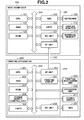
- Fig. 2 is a hardware block diagram of the printing system illustrated in Fig. 1 .
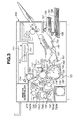
- Fig. 3 is a diagram illustrating an internal structure of a printing mechanism of the printing apparatus illustrated in Fig. 1 .
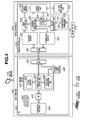
- Fig. 4 is a functional block diagram of the printing system illustrated in Fig. 1 .
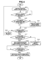
- Fig. 5 is a flowchart illustrating a method for controlling the host computer illustrated in Fig. 1 .
- Fig. 6 is a flowchart illustrating a method for controlling the printing apparatus illustrated in Fig. 1 .
- Fig. 7 is a flowchart illustrating a method for controlling a host computer according to a second exemplary embodiment of the present invention.
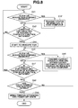
- Fig. 8 is a flowchart illustrating a method for controlling a printing apparatus according to the second exemplary embodiment of the present invention.
- Fig. 9 is a flowchart illustrating a method for controlling a host computer according to a third exemplary embodiment of the present invention.
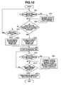
- Fig. 10 is a flowchart illustrating a method for controlling a printing apparatus according to the third exemplary embodiment of the present invention.
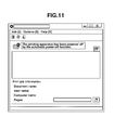
- Fig. 11 is a diagram illustrating a screen of a display monitor of a host computer when a printing apparatus enters a power-off state by an automatic power-off function.
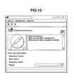
- Fig. 12 is a diagram illustrating a screen of a display monitor of a host computer when communication with a printing apparatus cannot be established.
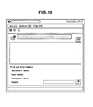
- Fig. 13 is a diagram illustrating a screen of a display monitor of a host computer when a printing apparatus enters a power-off state due to turning off of a power switch.
- a printing system (image forming system) 1 includes a host computer (information processing apparatus) 100 and a printing apparatus (image forming apparatus) 200 which can be connected to the host computer 100 through a network 300.
- the host computer 100 and the printing apparatus 200 communicate through a bidirectional interface 150 (see Fig. 2 ).
- the bidirectional interface 150 may be a wired one such as a local area network (LAN) and a Universal Serial Bus (USB), or a wireless one such as a wireless LAN.
- LAN local area network
- USB Universal Serial Bus
- the host computer 100 includes a controller 120, a keyboard 109, a display monitor (display section) 110, and an external memory 111.
- the controller 120 includes a central processing unit (CPU) 101, a random access memory (RAM) 102, a read only memory (ROM) 103, a keyboard controller (hereinafter, referred to as KBC) 105, a cathode-ray tube (CRT) controller (hereinafter, referred to as CRTC) 106, a memory controller (hereinafter, referred to as MC) 107, and an interface unit (I/F unit) 108.
- CPU central processing unit
- RAM random access memory
- ROM read only memory
- KBC keyboard controller
- KBC cathode-ray tube
- MC memory controller
- I/F unit interface unit
- the CPU 101 controls the devices connected to the system bus 104.
- the CPU 101 performs various types of data processing based on programs stored in the ROM 103.
- the CPU 101 processes a document which includes figures, images, characters, and tables (including spreadsheets) based on a document processing program stored in the ROM 103.
- the CPU 101 rasterizes outline fonts in a display information RAM allocated to the RAM 102, thereby implementing what-you-see-is-what-you-get (WYSIWYG) display on a CRT display.
- the CPU 101 opens various windows and performs various types of data processing based on commands designated by a mouse cursor on the display monitor 110.
- the RAM 102 functions as a main memory and a work area of the CPU 101.
- the ROM 103 includes a font ROM, a program ROM, and a data ROM.
- the font ROM stores font data for use in document processing.
- the program ROM stores a control program for controlling the host computer 100 and other programs such as a printer selector and a network printer driver.
- the data ROM stores various types of data for use in document processing.
- the KBC 105 controls input from the keyboard 109 and a pointing device (not illustrated).
- the CRTC 106 controls display of the display monitor 110.
- the MC 107 controls input and output from/to the external memory 111 which stores a boot program, various types of applications, font data, user files, and edit files.
- the external memory 111 include a hard disk drive (HDD).
- the I/F unit 108 controls communications performed by the printing apparatus 200 through the bidirectional interface 150.
- the printing apparatus 200 includes a printer controller 210, a printing mechanism unit 220, an operation unit 230, an HDD 207, and a power switch 211.
- the printing apparatus 200 operates in power states including a standby state (first power state) and a power-off state (second power state).
- the printer controller 210, the printing mechanism unit 220, the operation unit 230, and the HDD 207 are supplied with power.
- the power-off state the foregoing supply of the power to the printer controller 210, the printing mechanism unit 220, the operation unit 230, and the HDD 207 is stopped.
- a shift to the power-off state occurs when the user turns off the power switch 211 or when an automatic power-off function to be described later is executed.
- the printer controller 210 includes a CPU 201, a RAM 202, a ROM 203, an I/F unit 301, a printing unit interface (hereinafter, referred to as a printing unit I/F unit) 205, an MC unit 206, a power supply control unit 208, and a timer 209. Such devices are connected to a system bus 204.
- the CPU 201 controls the devices connected to the system bus 204.
- the CPU 201 executes a control program stored in the ROM 23 to perform data processing.
- the CPU 201 generates image data and outputs an image signal related to the image data to the printing mechanism unit 200 through the printing unit I/F unit 205.
- the CPU 201 transmits a control signal to the printing mechanism unit 200 through the printing unit I/F unit 205.
- the CPU 201 further transmits information about the printing apparatus 200 to the host computer 100 through the I/F unit 301.
- the RAM 202 functions as a main memory and a work area of the CPU 201. Optional RAMs can be added to not-illustrated expansion ports to expand the memory capacity of the RAM 202.
- the RAM 202 also functions as an image data storage area for storing rasterized image data, an environment data storage area for storing environment data, and a nonvolatile RAM (NVRAM) for storing various parameters.
- NVRAM nonvolatile RAM
- the ROM 203 includes a font ROM, a program ROM, and a data ROM.
- the font ROM stores font data that is used for generating image data.
- the program ROM stores a control program to be executed by the CPU 201.
- the data ROM stores various types of data for use in data processing.
- the I/F unit 301 controls communications performed by the host computer 100 through the bidirectional interface 150.
- the printing unit I/F unit 205 controls communications with the printing mechanism unit 220.
- the operation unit 230 is an operation panel for making key inputs and displaying information.
- the operation unit 230 includes switches and light-emitting diode (LED) indicators.
- the operation unit 230 may be a touch panel.
- the MC unit 206 controls access to the HDD 207.
- the HDD 207 stores print data and a control program.
- the power supply control unit 208 controls the supply and stop of power to the components of the printing apparatus 200 in response to a signal from the CPU 101.
- the power supply control unit 208 supplies power to the printer controller 210, the printing mechanism unit 220, the operation unit 230, and the HDD 207.
- the power supply control unit 208 stops the supply of the power to the printer controller 210, the printing mechanism unit 220, the operation unit 230, and the HDD 207.
- the printing apparatus 200 becomes unable to notify information to the host computer 100 since the supply of the power to the I/F unit 301 of the printer controller 210 is stopped.
- the timer 209 starts to measure time when a condition for the execution of the automatic power-off function to be described later is satisfied and when the power switch 211 is turned off.
- the power switch 211 is a switch for the user to operate when supplying power to the components of the printing apparatus 200 and stopping the supply of the power to the components of the printing apparatus 200.
- the power switch 211 is connected to the CPU 201 through the system bus 204. Each time the user depresses the power switch 211, the power switch 211 transmits a signal to the CPU 201.
- the present exemplary embodiment deals with a case where the printing apparatus 200 described above is a laser beam printer of a rotating development rotary type.
- a scanner 711 includes a laser output unit (not illustrated), a polyhedral polygonal mirror 712, a motor (not illustrated) which rotates the polygonal mirror 712, and an f/ ⁇ lens (imaging lens) 713.
- the laser output unit converts an image signal from the printer controller 210 into a light signal (laser light).
- the laser light emitted from the laser output unit is reflected by one of the side surfaces of the polygonal mirror 712, and passes the f/ ⁇ lens 713 and a reflection mirror 714.
- the surface of a photosensitive drum 715 is linearly scanned (raster scans) with the laser light.
- the photosensitive drum 715 rotates in the direction of the illustrated arrow.
- An electrostatic latent image corresponding to an image expressed by the image signal is thus formed on the surface of the photosensitive drum 715.
- a primary charging unit 717, a whole surface exposure lamp 718, a cleaner unit 723, and a pre-transfer charging unit 724 are arranged around the photosensitive drum 715.
- the cleaner unit 723 collects toner which has not been transferred to a sheet (residual toner).
- a developing device unit 726 is a unit for developing the electrostatic latent image formed on the surface of the photosensitive drum 715.
- the developing device unit 726 has the following configuration.
- Toner cartridges 730C, 730M, 730Y, and 730BK store toners, or developers.
- Developing sleeves 731C, 731M, 731Y, and 731BK each make contact with the photosensitive drum 715 to perform development by using the developers.
- Screws 732 convey the developers stored in the toner cartridges 730C, 730M, 730Y, and 730BK to the developing sleeves 731C, 731M, 731Y, and 731BK, respectively. More specifically, cyan, magenta, yellow, and black developers are used to form toner images on the photosensitive drum 715.
- the toner cartridges 730C, 730M, 730Y, and 730BK, the developing sleeves 731C, 731M, 731Y, and 731BK, and the screws 732 are arranged around a center axis P of the developing device unit 726.
- the symbols Y, M, C, and BK of the components represent different colors. Specifically, C represents cyan, M magenta, Y yellow, and BK black.
- a position sensor 742 detects a rotational position of the developing device unit 726.
- a not-illustrated motor rotates the developing device unit 726 about the center axis P so that the developing sleeve 731Y comes into contact with the photosensitive drum 715.
- Fig. 2 illustrates such a state.
- the motor rotates the developing device unit 726 about the center axis P so that the developing sleeve 731M comes into contact with the photosensitive drum 715. Cyan and black toner images are formed in a similar manner.
- a transfer drum 716 transfers the toner images formed on the photosensitive drum 715 to a sheet.
- An actuator plate 719 detects a moving position of the transfer drum 716.
- a position sensor 720 lies close to the actuator plate 719 to detect that the transfer drum 716 has reached a home position.
- the actuator plate 719, the position sensor 720, a transfer drum cleaner unit 725, a paper pressing roller 727, and a discharging unit or transfer charging unit 729 are arranged around the transfer drum 716.
- Sheet feeding cassettes 735 and 736 store sheets 791.
- the sheet feeding cassette 735 stores A4-sized sheets.
- the sheet feeding cassette 736 stores A3-sized sheets.
- sheet feeding rollers 737 and 738 feed a sheet from the sheet feeding cassettes 735 and 736, respectively.
- Timing rollers 739, 740, and 741 control timing for performing sheet feeding and sheet conveyance. A sheet is passed between the timing rollers 739, 740, and 741, guided by a paper guide 490, and wound about the transfer drum 716 with its leading edge carried by a gripper 728. Whether the sheet feeding cassette 735 or 736 is to be selected is determined by an instruction from the printer controller 210. Only the feeling roller corresponding to the selected sheet feeding cassette is rotated.
- the host computer 100 functions as a server or a client.
- the host computer 100 includes input/output devices such as the keyboard 109, a mouse 112, and the display monitor 110.
- the host computer 100 operates based on a basic operating system (OS) 410.
- the host computer 100 operating on the basic OS 410 is provided with application software 400, a graphic device interface (GDI) 402, a printer driver 420, and a system print spooler 406.
- the GDI 402 is a part of the basic OS 410.
- the application software 400, the basic OS 410, and the printer driver 420 are stored in the external memory 111.
- the RAM 102 described above functions as the system print spooler 406.
- the system print spooler 406 temporarily stores data generated by the printer driver 420.
- BIOS basic input-output system
- the printer driver 420 is a piece of such application software.
- the application software 400 of Fig. 4 refers to application software that runs on the basic software such as a word processor program and a spreadsheet program. A plurality of pieces of application software may be activated at arbitrary timing (depending on the capacity of the main memory).
- the user performs an image editing operation by using the application software 400.
- To print an edited image the user selects a print menu displayed on the display monitor 110 by using the mouse 112 and executes printing.
- the application software 400 calls the GDI 402, a part of the functions of the basic OS 410.
- the GDI 402 includes a group of basic functions for controlling display devices and printing devices, including screen display and print output.
- Application software from various vendors uses the group of basic functions such that the application software can be run without being aware of model (hardware)-dependent portions.
- the printer driver 420 manages information dependent on the models of respective printing apparatuses.
- the GDI 402 acquires information about the drawing capabilities and printing resolution of the printing device (in the present case, the printing apparatus 200) from the printer driver 420.
- the GDI 402 then processes an application program interface (API) function called by the application software 400, and calls a function the printer driver 420 provides for the GDI 402 according to the processing content.
- API application program interface
- the function is constituted as a predetermined interface (device driver interface: DDI).
- a creator of a printer driver creates the printer driver mostly by dealing with data conversion from such an interface to an actual printing apparatus.
- a print data generation processing unit 405 performs processing for generating print data (image bitmap data) based on DDI information received from the GDI 402 and print environment settings made by its own graphical user interface (GUI).
- the print data generation processing unit 405 then outputs the print data to a system print spooler 406.
- the print data output to the system print spooler 406 is output to the printing apparatus 200 through the I/F unit 108.
- a printer status control unit 404 issues a status acquisition command to the printing apparatus 200 and thereby monitors a status of the printing apparatus 200.
- a status monitor 403 displays the status of the printing apparatus 200.
- the printing apparatus 200 mainly includes the printer controller 210, the operation unit 230, and the printing mechanism unit 220.
- the printer controller 210 includes an I/F unit 301, a reception buffer 302, a transmission buffer 303, an image buffer 305, a command analysis unit 306, a printing control unit 307, an image control unit 304, an output control unit 309, a status management unit 308, and a power supply management unit 310.
- the I/F unit 301 is a unit for connecting to the host computer 100.
- the reception buffer 302 temporarily stores and manages reception data.
- the transmission buffer 303 temporarily stores and manages transmission data.
- the command analysis unit 306 analyzes print data.
- the RAM 202 of the printing apparatus 200 functions as the reception buffer 302, the transmission buffer 303, and the image buffer 305.
- the CPU 201 of the printing apparatus 200 functions as the command analysis unit 306, the printing control unit 307, the image control unit 304, and the status management unit 308.
- the power supply control unit 208 of the printing apparatus 200 functions as the power supply management unit 310.
- the printing unit I/F unit 205 of the printing apparatus 200 functions as the output control unit 309.
- the I/F unit 301 is a communication unit that transmits and receives information (such as print data) to/from the host computer 100.
- Print data output from the host computer 100 is temporarily stored into the reception buffer 302 through the I/F unit 301.
- the print data stored in the reception data buffer 302 is read and processed by the command analysis unit 306 and/or the image control unit 304 when needed.
- the command analysis unit 306 includes control programs conforming to respective print control command systems and print job control languages. If a command analyzed by the command analysis unit 306 is related to image data such as bitmap data, the command analysis unit 306 outputs an instruction to the image control unit 304. If a command analyzed by the command analysis unit 306 is a non-drawing command such as a paper feeding selection command and a reset command, the command analysis unit 306 outputs an instruction to the printing control unit 307.
- the image control unit 304 removes a command portion from transferred image data command data. If the resultant is compressed image data, the image control unit 304 performs decompression processing and stores the resulting data into the image buffer 305.
- the status management unit 308 determines the status of the printing apparatus 200 based on information output from the printing control unit 307, and makes the operation unit 230 display the state of the printing apparatus 200.
- the status management unit 308 sends back status information indicating the status of the printing apparatus 200 in response to the status acquisition command transmitted from the host computer 100.
- the power supply management unit 310 controls the supply of the power to the printing mechanism unit 220 according to an instruction from the status management unit 308.
- the output control unit 309 performs processing for converting the image bitmap data stored in the image buffer 305 into a video image, and outputs the video signal to the printing mechanism unit 220.
- the printing mechanism unit 200 receives the video signal output from the output control unit 309 and forms an image on a recording sheet.
- step S11 the CPU 101 initially issues the status acquisition command to the printing apparatus 200.
- step S12 the CPU 101 determines whether the status information indicating the status of the printing apparatus 200 is sent back from the printing apparatus 200.
- the CPU 101 waits (NO in step S12) until the status information is sent back from the printing apparatus 200. If the CPU 101 receives the status information of the printing apparatus 200 (YES in step S12), then in step S13, the CPU 101 determines whether the received status information of the printing apparatus 200 includes information indicating an automatic power-off advance notification.
- step S14 the CPU 101 records in the RAM 102 that the automatic power-off advance notification is received.
- the automatic power-off advance notification is information (power shift information) to be transmitted from the printing apparatus 200 to the host computer 100 when the printing apparatus 200 satisfies any one of conditions for the execution of the automatic power-off function to be described later.
- the host computer 100 is informed that the printing apparatus 200 enters the power-off state by the automatic power-off function.
- step S15 the CPU 101 monitors the communication state with the printing apparatus 200. If the CPU 101 determines that the communication with the printing apparatus 200 is normal (NO in step S15), then in step S16, the CPU 101 waits a certain period of time (for example, 500 ms) and returns to step S11. In other words, the CPU 101 polls the status information of the printing apparatus 200 at regular intervals (repeats steps S11 to S15).
- a certain period of time for example, 500 ms
- step S17 the CPU 101 determines whether it is recorded in the RAM 102 that the automatic power-off advance notification is received.
- the CPU 101 monitors signals transmitted and received to/from the printing apparatuses 200, and if an interruption of the signal transmission and reception is detected, determines that the communication with the printing apparatus 200 is disabled.
- step S18 the CRTC 106 displays contents indicating that the printing apparatus 200 has been powered off by the automatic power-off function on the display monitor 110. Specifically, as illustrated in Fig. 11 , the CRTC 106 displays a screen saying that the "printing apparatus has been powered off by the automatic power-off function" on the display monitor 110.
- the CPU 101 deletes the record that the automatic power-off advance notification is received. In the present exemplary embodiment, the CPU 101 continues polling the status information of the printing apparatus 200 even after the foregoing screen is displayed.
- step S17 the CRTC 106 displays contents indicating that the communication with the printing apparatus 200 is disabled on the display monitor 110. Specifically, as illustrated in Fig. 12 , the CRTC 106 displays a message "communication error" on the display monitor 110. The CRTC 106 continues displaying the contents while the host computer 100 is not able to communicate with the printing apparatus 200.
- step S110 the CPU 101 determines whether the communication with the printing apparatus 200 is established. Specifically, the CPU 101 monitors the signals to be transmitted and received to/from the printing apparatus 200, and if the resumption of the signal transmission and reception is detected, determines that the communication with the printing apparatus 200 is resumed. The CPU 101 waits (NO in step S110) until the communication with the printing apparatus 200 is established. If the CPU 101 determines that the communication with the printing apparatus 200 is established (YES in step S110), then in step S111, the CRTC 106 displays the current status of the printing apparatus 200 on the display monitor 110.
- the CPU 101 continues polling the status information of the printing apparatus 200 even after step S18.
- the CPU 101 can thus acquire the status information of the printing apparatus 200 when the communication with the printing apparatus 200 is established.
- the CPU 101 then displays the current status of the printing apparatus 200 on the display monitor 110 based on the acquired status information of the printing apparatus 200.
- step S21 the CPU 201 determines whether the status acquisition command transmitted from the host computer 100 is received. If the status acquisition command is determined to be received (YES in step S21), then in step S22, the CPU 201 generates status information indicating the current status of the printing apparatus 200 and transmits the status information to the host computer 100. In step S23, the CPU 201 determines whether a condition for the execution of the automatic power-off function is satisfied.
- step S23 If the CPU 201 determines that neither of the foregoing conditions for the execution of the automatic power-off function is satisfied (NO in step S23), the CPU 201 returns to step S21. On the other hand, if the CPU 201 determines that any one of the conditions for the execution of the automatic power-off function is satisfied (YES in step S23), then in step S24, the timer 209 starts to measure time.
- step S28 if the time measured by the timer 209 has reached a predetermined time set in advance (YES in step S27), then in step S28, the CPU 201 transmits a signal to the power supply control unit 208, and the power supply control unit 208 brings the printing apparatus 200 into the power-off state. In other words, even if any one of the conditions for the execution of the automatic power-off function is satisfied, the printing apparatus 200 according to the present exemplary embodiment will not immediately enter the power-off state.
- An example of the predetermined time is 10 seconds. The predetermined time is needed for the host computer 100 connected to the printing apparatus 200 to surely acquire the automatic power-off advance notification by polling.
- step S25 after the timer 209 starts to measure the predetermined time in step S24, the CPU 201 determines whether the status acquisition command transmitted from the host computer 100 is received. If the CPU 201 determines that the status acquisition command is received (YES in step S25), then in step S26, the CPU 201 transmits the current status of the printing apparatus 200 and the automatic power-off advance notification to the host computer 100.
- step S27 the CPU 201 determines whether the time measured by the timer 209 has reached the predetermined time (for example, 10 seconds). If the CPU 201 determines that the time measured by the timer 209 has reached the predetermined time, e.g., 10 seconds (YES in step S27), then in step S28, the CPU 201 transmits a signal to the power supply control unit 208, and the power supply control unit 208 brings the printing apparatus 200 into the power-off state.
- the predetermined time for example, 10 seconds
- the printing apparatus 200 if the printing apparatus 200 has entered the power-off state by the automatic power-off function, no power is supplied to the printer controller 210 which is typified by the CPU 201 and the I/F unit 301. The printing apparatus 200 in the power-off state thus becomes unable to reply to an inquiry from the host computer 100.
- the CPU 201 determines that the predetermined time has not yet elapsed (NO in step S27), then in step S25, the CPU 201 determines again whether the status acquisition command transmitted from the host computer 100 is received.
- the printing apparatus 200 can transmit the automatic power-off advance notification to the host computer 100 connected to the printing apparatus 200 before the printing apparatus 200 enters the power-off state by the automatic power-off function of the printing apparatus 200. Consequently, the message "the printing apparatus has been powered off by the automatic power-off function" can be displayed on the display monitor 110 of the host computer 100. The user can thus recognize that the printing apparatus 200 enters the power-off state by the automatic power-off function.
- the printing apparatus 200 when any one of the conditions for the execution of the automatic power-off function is satisfied, the printing apparatus 200 will not immediately enter the power-off state but instead can wait a predetermined time before entering the power-off state. In such a predetermined time, the host computer 100 can surely acquire the automatic power-off advance notification by polling.
- the second exemplary embodiment deals with a method for controlling the printing system when the automatic power-off function is cancelled or delayed after the host computer 100 receives the automatic power-off advance notification.
- a method for controlling the host computer 100 will initially be described with reference to the flowchart of Fig. 7 .
- Such a control method is implemented by the CPU 101 of the host computer 100 executing a program based on the flowchart of Fig. 7 .
- steps S31 to S34 is similar to that of steps S11 to S14 of the first exemplary embodiment, respectively. A description thereof will be omitted. If, in step S33, the CPU 101 determines that the received status information of the printing apparatus 200 does not include the automatic power-off advance notification (NO in step S33), then in step S35, the CPU 101 determines whether there is a record that the automatic power-off notification is received. If the CPU 101 determines that there is the record that the automatic power-off advance notification is received (YES in step S35), then in step S36, the CPU 101 deletes the record. The CPU 101 then performs the processing of step S37 and subsequent steps.
- step S35 determines that there is no record that the automatic power-off advance notification is received (NO in step S35)
- the CPU 101 performs the processing of step S37 and subsequent steps.
- the processing of step S37 and subsequent steps is similar to that of step S15 and subsequent steps according to the first exemplary embodiment. A description thereof will be omitted. Description of Operation of Printing Apparatus
- steps S41 to S46 is similar to that of steps S21 to S26 of the first exemplary embodiment, respectively. A description thereof will be omitted. If, in step S43, a condition for the execution of the automatic power-off function is satisfied (YES in step S43), then in step S44, the timer 209 measures the predetermined time. In step S47, the CPU 201 determines whether a condition for cancelling the execution of the automatic power-off function is satisfied. If the CPU 201 determines that the condition for cancelling the execution of the automatic power-off function is satisfied (YES in step S47), the CPU returns to step S41 and repeats the processing of steps S41 to S46. On the other hand, if the CPU 201 determines that the condition for cancelling the execution of the automatic power-off function is not satisfied (NO in step S47), the CPU 201 performs the processing of steps S48 and S49.
- steps S48 and S49 is the same as that of steps S27 and 28 of the first exemplary embodiment, respectively. A description thereof will be omitted.
- the foregoing condition for cancelling the execution of the automatic power-off function is satisfied when the power switch 211 is turned on. Such a condition for cancelling the execution of the automatic power-off function is just an example. Exemplary embodiments of the present invention are not limited thereto.
- the host computer 100 deletes the record that the automatic power-off advance notification is received if a condition for the execution of the automatic power-off function is satisfied and then the condition for cancelling the execution of the automatic power-off function is satisfied. As a result, the host computer 100 can display the correct status of the printing apparatus 200 on the display monitor 110.
- the third exemplary embodiment deals with a method for controlling the printing system not only when the printing apparatus 200 enters the power-off state by the automatic power-off function but also when the printing apparatus 200 is powered off by a user's operation on the power switch 211.
- a method for controlling the host computer 100 will initially be described with reference to the flowchart of Fig. 9 .
- Such a control method is implemented by the CPU 101 of the host computer 100 executing a program based on the flowchart of Fig. 9 .
- steps S51 to S54 is similar to that of steps S11 to S14 of the first exemplary embodiment, respectively. A description thereof will be omitted.
- step S55 the CPU 101 determines whether the status information includes information indicating a manual power-off advance notification. If the status information received by the CPU 101 is determined to include the information indicating the manual power-off advance notification (YES in step S55), then in step S56, the CPU 101 records in the RAM 102 that the manual power-off advance notification is received. In step S57, the CPU 101 then monitors the communication state of the printing apparatus 200.
- step S57 the CPU 101 monitors the communication state of the printing apparatus 200.
- the manual power-off advance notification is information to be transmitted from the printing apparatus 200 to the host computer 100 when the power switch 211 of the printing apparatus is turned off by a user's operation. By receiving the notification, the host computer 100 is informed that the printing apparatus 200 is manually brought into the power-off state.
- step S57 the CPU 101 determines that the communication with the printing apparatus 200 is normal (NO in step S57)
- step S58 the CPU 101 waits a certain period of time (for example, 500 ms) and returns to step S51.
- the CPU 101 polls the status information of the printing apparatus 200 at regular intervals (repeats steps S51 to S56).
- step S57 determines whether it is recorded in the RAM 102 that the automatic power-off advance notification is received. If the CPU 101 determines that there is a record that the automatic power-off advance notification is received (YES in step S59), then in step S510, the CRTC 106 displays contents indicating that the printing apparatus 200 enters the power-off state by the automatic power-off function (see Fig. 11 ) on the display monitor 110. Here, the CPU 101 deletes the record of the reception of the automatic power-off advance notification.
- step S511 the CPU 101 determines whether it is recorded that the manual power-off advance notification is received. If there is a record that the manual power-off advance notification is received (YES in step S511), then in step S512, the CRTC 106 displays contents indicating that the printing apparatus 200 is powered off by a user's operation on the power switch 211. Specifically, as illustrated in Fig. 13 , a message "the printing device is powered off by a user operation" is displayed on the display monitor 110. Here, the CPU 101 deletes the record of the reception of the manual power-off advance notification.
- step S511 the CPU 101 determines that it is not recorded that the CPU 101 has received the manual power-off advance notification (NO in step S511), then in step S513, the CRTC 106 displays contents indicating that the communication with the printing apparatus 200 is disabled (see Fig. 12 ).
- the CRTC 106 continues displaying the foregoing contents as long as the host computer 100 cannot communicate with the printing apparatus 200.
- the CPU 101 determines whether the communication with the printing apparatus 200 is established. The CPU 101 waits (NO in step S514) until the communication with the printing apparatus 200 is established. If the communication with the printing apparatus 200 is determined to be established (YES in step S514), then in step S515, the CRTC 106 displays the current status of the printing apparatus 200 on the display monitor 110.
- steps S61 to S63 is similar to that of steps S21 to S23 of the first exemplary embodiment, respectively. A description thereof will be omitted.
- step S63 the CPU 201 determines that a condition for the execution of the automatic power-off function is satisfied (YES in step S63), then in step S66, the CPU 201 records in the RAM 102 that the printing apparatus 200 has entered the power-off state by the automatic power-off function as a reason for power-off. On the other hand, if the CPU 201 determines that no condition for the execution of the automatic power-off function is satisfied (NO in step S63), then in step S64, the CPU 201 determines whether the power switch 211 is turned off.
- step S65 the CPU 201 records the turning off of the power switch 211 as a reason for power-off state. On the other hand, if the CPU 201 determines that the power switch 211 is not turned off (NO in step S64), the CPU 201 returns to step S61.
- step S67 the timer 209 measures time.
- step S68 after the timer 209 has started to measure a predetermined time in step S67, the CPU 201 determines whether the status acquisition command transmitted from the host computer 100 is received. If the CPU 201 determines that the status acquisition command is received (YES in step S68), then in step S69, the the CPU 201 transmits the current status of the printing apparatus 200 and the reason that the printing apparatus 200 enters the power-off state, recorded in step S65 or S66, to the host computer 100.
- step S610 the CPU 201 determines whether the time measured by the timer 209 has reached the predetermined time (for example, 10 seconds). If the CPU 201 determines that the time measured by the timer 209 has reached the predetermined time (YES in step S610), then in step S611, the CPU 201 brings the printing apparatus 200 into the power-off state. On the other hand, if the CPU 201 determines that the predetermined time has not elapsed (NO in step S610), then in step S68, the CPU 201 determines again whether the status acquisition command transmitted from the host computer 100 is received.
- the predetermined time for example, 10 seconds
- different contents are displayed on the display monitor 110 when the printing apparatus 200 enters the power-off state by the automatic power-off function, and when a user manually operates the power switch 211 to bring the printing apparatus 200 into the power-off state. A user can thus be informed of the reason that the printing apparatus 200 has entered the power-off state for.
- a printing apparatus may be a printer of other printing methods such as an inkjet printer and a thermal (thermal transfer) printer.
- An exemplary embodiment of the present invention may be practiced by performing the following processing.
- the processing includes supplying software (program) for implementing the functions of the foregoing exemplary embodiments to a system or an apparatus through a network or various types of storage media, and reading and executing the program by a computer (or CPU or microprocessing unit (MPU)) of the system or apparatus.
- software program
- MPU microprocessing unit
Landscapes
- Engineering & Computer Science (AREA)
- Theoretical Computer Science (AREA)
- General Engineering & Computer Science (AREA)
- Physics & Mathematics (AREA)
- General Physics & Mathematics (AREA)
- Human Computer Interaction (AREA)
- Computer Hardware Design (AREA)
- Software Systems (AREA)
- Quality & Reliability (AREA)
- Accessory Devices And Overall Control Thereof (AREA)
- Power Sources (AREA)
- Facsimiles In General (AREA)
Abstract
Description
- The present invention relates to an information processing apparatus which acquires a state of an image forming apparatus, a method for controlling an information processing apparatus, an image forming apparatus, a method for controlling an image forming apparatus, a recording medium, and a program.
- A system that can display a status of a network-connected device on a display section of an information processing apparatus is known. A status display application such as a printer driver is used to display the status of the device on the display section of the information processing apparatus. To acquire the status of the device, the information processing apparatus in the system regularly transmits a status acquisition command to the network-connected device. The device in the system sends back status information indicating the status of the device in response to the status acquisition command transmitted from the information processing apparatus. As a result, the information processing apparatus can display the status of the device on the display section (see Japanese Patent Application Laid-Open Nos.
2002-077689 2002-059616 - When the device is powered off, the device becomes unable to send back the status information of the device to the information processing apparatus. When the information processing apparatus transmits a status acquisition command and gets no reply to the command, the information processing apparatus determines that the communication with the device is disabled, and displays a message "communication error" on the display section. The message "communication error," however, can be displayed not only when the device is powered off but also for the following reasons:
- The turning off of a power switch by a user's operation;
- An unplugged network cable or failed network cable;
- A communication failure (the network going down) due to a trouble in the network environment; and
- IP address misconfiguration.
- Since the foregoing message "communication error" can be displayed because of such various reasons, the user cannot identify the reason why the communication with the device is disabled. Take, for example, a handy device such as a camera. When a camera is powered off, the user can recognize it and can determine that the communication between the device and the information processing apparatus is disabled because the device is powered off. On the other hand, in an environment where the information processing apparatus and the device are located in remote locations over a network, the user cannot recognize that the device is powered off. The user is thus unable to identify the reason why the communication with the device is disabled.
- The present invention is directed to displaying, when an external apparatus enters a low power state, that the external apparatus enters the low power state, on a display section of an information processing apparatus.
- The present invention in its first aspect provides an information processing apparatus as specified in
claims 1 to 7. - Further features and aspects of the present invention will become apparent from the following detailed description of exemplary embodiments with reference to the attached drawings.
- The accompanying drawings, which are incorporated in and constitute a part of the specification, illustrate exemplary embodiments, features, and aspects of the invention and, together with the description, serve to explain the principles of the invention.
-
Fig. 1 is a diagram illustrating an overall configuration of a printing system according to a first exemplary embodiment of the present invention. -
Fig. 2 is a hardware block diagram of the printing system illustrated inFig. 1 . -
Fig. 3 is a diagram illustrating an internal structure of a printing mechanism of the printing apparatus illustrated inFig. 1 . -
Fig. 4 is a functional block diagram of the printing system illustrated inFig. 1 . -
Fig. 5 is a flowchart illustrating a method for controlling the host computer illustrated inFig. 1 . -
Fig. 6 is a flowchart illustrating a method for controlling the printing apparatus illustrated inFig. 1 . -
Fig. 7 is a flowchart illustrating a method for controlling a host computer according to a second exemplary embodiment of the present invention. -
Fig. 8 is a flowchart illustrating a method for controlling a printing apparatus according to the second exemplary embodiment of the present invention. -
Fig. 9 is a flowchart illustrating a method for controlling a host computer according to a third exemplary embodiment of the present invention. -
Fig. 10 is a flowchart illustrating a method for controlling a printing apparatus according to the third exemplary embodiment of the present invention. -
Fig. 11 is a diagram illustrating a screen of a display monitor of a host computer when a printing apparatus enters a power-off state by an automatic power-off function. -
Fig. 12 is a diagram illustrating a screen of a display monitor of a host computer when communication with a printing apparatus cannot be established. -
Fig. 13 is a diagram illustrating a screen of a display monitor of a host computer when a printing apparatus enters a power-off state due to turning off of a power switch. - Various exemplary embodiments, features, and aspects of the invention will be described in detail below with reference to the drawings.
- As illustrated in
Fig. 1 , a printing system (image forming system) 1 according to a first exemplary embodiment of the present invention includes a host computer (information processing apparatus) 100 and a printing apparatus (image forming apparatus) 200 which can be connected to thehost computer 100 through anetwork 300. In theprinting system 1, thehost computer 100 and theprinting apparatus 200 communicate through a bidirectional interface 150 (seeFig. 2 ). Thebidirectional interface 150 may be a wired one such as a local area network (LAN) and a Universal Serial Bus (USB), or a wireless one such as a wireless LAN. - As illustrated in
Fig. 2 , thehost computer 100 includes acontroller 120, akeyboard 109, a display monitor (display section) 110, and anexternal memory 111. - The
controller 120 includes a central processing unit (CPU) 101, a random access memory (RAM) 102, a read only memory (ROM) 103, a keyboard controller (hereinafter, referred to as KBC) 105, a cathode-ray tube (CRT) controller (hereinafter, referred to as CRTC) 106, a memory controller (hereinafter, referred to as MC) 107, and an interface unit (I/F unit) 108. Such devices are connected to asystem bus 104. - The
CPU 101 controls the devices connected to thesystem bus 104. TheCPU 101 performs various types of data processing based on programs stored in theROM 103. For example, theCPU 101 processes a document which includes figures, images, characters, and tables (including spreadsheets) based on a document processing program stored in theROM 103. TheCPU 101 rasterizes outline fonts in a display information RAM allocated to theRAM 102, thereby implementing what-you-see-is-what-you-get (WYSIWYG) display on a CRT display. TheCPU 101 opens various windows and performs various types of data processing based on commands designated by a mouse cursor on thedisplay monitor 110. - The
RAM 102 functions as a main memory and a work area of theCPU 101. - The
ROM 103 includes a font ROM, a program ROM, and a data ROM. The font ROM stores font data for use in document processing. The program ROM stores a control program for controlling thehost computer 100 and other programs such as a printer selector and a network printer driver. The data ROM stores various types of data for use in document processing. - The KBC 105 controls input from the
keyboard 109 and a pointing device (not illustrated). - The CRTC 106 controls display of the
display monitor 110. - The
MC 107 controls input and output from/to theexternal memory 111 which stores a boot program, various types of applications, font data, user files, and edit files. Examples of theexternal memory 111 include a hard disk drive (HDD). - The I/
F unit 108 controls communications performed by theprinting apparatus 200 through thebidirectional interface 150. - As illustrated in
Fig. 2 , theprinting apparatus 200 includes aprinter controller 210, aprinting mechanism unit 220, anoperation unit 230, anHDD 207, and apower switch 211. Theprinting apparatus 200 operates in power states including a standby state (first power state) and a power-off state (second power state). In the standby state, theprinter controller 210, theprinting mechanism unit 220, theoperation unit 230, and theHDD 207 are supplied with power. In the power-off state, the foregoing supply of the power to theprinter controller 210, theprinting mechanism unit 220, theoperation unit 230, and theHDD 207 is stopped. A shift to the power-off state occurs when the user turns off thepower switch 211 or when an automatic power-off function to be described later is executed. - The
printer controller 210 includes aCPU 201, aRAM 202, aROM 203, an I/F unit 301, a printing unit interface (hereinafter, referred to as a printing unit I/F unit) 205, anMC unit 206, a powersupply control unit 208, and atimer 209. Such devices are connected to asystem bus 204. - The
CPU 201 controls the devices connected to thesystem bus 204. TheCPU 201 executes a control program stored in the ROM 23 to perform data processing. For example, theCPU 201 generates image data and outputs an image signal related to the image data to theprinting mechanism unit 200 through the printing unit I/F unit 205. TheCPU 201 transmits a control signal to theprinting mechanism unit 200 through the printing unit I/F unit 205. TheCPU 201 further transmits information about theprinting apparatus 200 to thehost computer 100 through the I/F unit 301. - The
RAM 202 functions as a main memory and a work area of theCPU 201. Optional RAMs can be added to not-illustrated expansion ports to expand the memory capacity of theRAM 202. TheRAM 202 also functions as an image data storage area for storing rasterized image data, an environment data storage area for storing environment data, and a nonvolatile RAM (NVRAM) for storing various parameters. - The
ROM 203 includes a font ROM, a program ROM, and a data ROM. The font ROM stores font data that is used for generating image data. The program ROM stores a control program to be executed by theCPU 201. The data ROM stores various types of data for use in data processing. - The I/
F unit 301 controls communications performed by thehost computer 100 through thebidirectional interface 150. - The printing unit I/
F unit 205 controls communications with theprinting mechanism unit 220. - The
operation unit 230 is an operation panel for making key inputs and displaying information. Theoperation unit 230 includes switches and light-emitting diode (LED) indicators. Theoperation unit 230 may be a touch panel. - The
MC unit 206 controls access to theHDD 207. TheHDD 207 stores print data and a control program. - The power
supply control unit 208 controls the supply and stop of power to the components of theprinting apparatus 200 in response to a signal from theCPU 101. In the standby state, the powersupply control unit 208 supplies power to theprinter controller 210, theprinting mechanism unit 220, theoperation unit 230, and theHDD 207. In the power-off state, the powersupply control unit 208 stops the supply of the power to theprinter controller 210, theprinting mechanism unit 220, theoperation unit 230, and theHDD 207. In the power-off state, theprinting apparatus 200 becomes unable to notify information to thehost computer 100 since the supply of the power to the I/F unit 301 of theprinter controller 210 is stopped. - The
timer 209 starts to measure time when a condition for the execution of the automatic power-off function to be described later is satisfied and when thepower switch 211 is turned off. - The
power switch 211 is a switch for the user to operate when supplying power to the components of theprinting apparatus 200 and stopping the supply of the power to the components of theprinting apparatus 200. Thepower switch 211 is connected to theCPU 201 through thesystem bus 204. Each time the user depresses thepower switch 211, thepower switch 211 transmits a signal to theCPU 201. - Next, the
printing mechanism unit 220 of theprinting apparatus 200 will be described in detail with reference toFig. 3 . The present exemplary embodiment deals with a case where theprinting apparatus 200 described above is a laser beam printer of a rotating development rotary type. - A
scanner 711 includes a laser output unit (not illustrated), a polyhedralpolygonal mirror 712, a motor (not illustrated) which rotates thepolygonal mirror 712, and an f/θ lens (imaging lens) 713. The laser output unit converts an image signal from theprinter controller 210 into a light signal (laser light). The laser light emitted from the laser output unit is reflected by one of the side surfaces of thepolygonal mirror 712, and passes the f/θ lens 713 and areflection mirror 714. The surface of aphotosensitive drum 715 is linearly scanned (raster scans) with the laser light. - The
photosensitive drum 715 rotates in the direction of the illustrated arrow. An electrostatic latent image corresponding to an image expressed by the image signal is thus formed on the surface of thephotosensitive drum 715. A primary charging unit 717, a wholesurface exposure lamp 718, acleaner unit 723, and apre-transfer charging unit 724 are arranged around thephotosensitive drum 715. Thecleaner unit 723 collects toner which has not been transferred to a sheet (residual toner). - A developing
device unit 726 is a unit for developing the electrostatic latent image formed on the surface of thephotosensitive drum 715. The developingdevice unit 726 has the following configuration.Toner cartridges sleeves photosensitive drum 715 to perform development by using the developers.Screws 732 convey the developers stored in thetoner cartridges sleeves photosensitive drum 715. - The
toner cartridges sleeves screws 732 are arranged around a center axis P of the developingdevice unit 726. The symbols Y, M, C, and BK of the components represent different colors. Specifically, C represents cyan, M magenta, Y yellow, and BK black. - A
position sensor 742 detects a rotational position of the developingdevice unit 726. To form a yellow toner image on thephotosensitive drum 715, a not-illustrated motor rotates the developingdevice unit 726 about the center axis P so that the developing sleeve 731Y comes into contact with thephotosensitive drum 715.Fig. 2 illustrates such a state. To form a magenta toner image, the motor rotates the developingdevice unit 726 about the center axis P so that the developingsleeve 731M comes into contact with thephotosensitive drum 715. Cyan and black toner images are formed in a similar manner. - A
transfer drum 716 transfers the toner images formed on thephotosensitive drum 715 to a sheet. Anactuator plate 719 detects a moving position of thetransfer drum 716. Aposition sensor 720 lies close to theactuator plate 719 to detect that thetransfer drum 716 has reached a home position. - The
actuator plate 719, theposition sensor 720, a transferdrum cleaner unit 725, apaper pressing roller 727, and a discharging unit ortransfer charging unit 729 are arranged around thetransfer drum 716. -
Sheet feeding cassettes store sheets 791. For example, thesheet feeding cassette 735 stores A4-sized sheets. Thesheet feeding cassette 736 stores A3-sized sheets. In sheet feeding and sheet conveyance,sheet feeding rollers sheet feeding cassettes rollers rollers paper guide 490, and wound about thetransfer drum 716 with its leading edge carried by agripper 728. Whether thesheet feeding cassette printer controller 210. Only the feeling roller corresponding to the selected sheet feeding cassette is rotated. - With the foregoing configuration, full color printing using four colors C, M, Y, and BK is performed.
- The
host computer 100 functions as a server or a client. Thehost computer 100 includes input/output devices such as thekeyboard 109, amouse 112, and thedisplay monitor 110. - As illustrated in
Fig. 4 , thehost computer 100 operates based on a basic operating system (OS) 410. Thehost computer 100 operating on thebasic OS 410 is provided withapplication software 400, a graphic device interface (GDI) 402, aprinter driver 420, and asystem print spooler 406. TheGDI 402 is a part of thebasic OS 410. Theapplication software 400, thebasic OS 410, and theprinter driver 420 are stored in theexternal memory 111. TheRAM 102 described above functions as thesystem print spooler 406. Thesystem print spooler 406 temporarily stores data generated by theprinter driver 420. - Software referred to as basic software (basic input-output system (BIOS)) controls the
host computer 100 with the hardware illustrated inFig. 3 , including theCPU 101, theRAM 102, theROM 103, and theexternal memory 111. Application software runs on the basic software. - The
printer driver 420 is a piece of such application software. Theapplication software 400 ofFig. 4 refers to application software that runs on the basic software such as a word processor program and a spreadsheet program. A plurality of pieces of application software may be activated at arbitrary timing (depending on the capacity of the main memory). - Next, a case where an image editing program is used as the
application software 400 will be described. - The user performs an image editing operation by using the
application software 400. To print an edited image, the user selects a print menu displayed on the display monitor 110 by using themouse 112 and executes printing. Next, theapplication software 400 calls theGDI 402, a part of the functions of thebasic OS 410. TheGDI 402 includes a group of basic functions for controlling display devices and printing devices, including screen display and print output. Application software from various vendors uses the group of basic functions such that the application software can be run without being aware of model (hardware)-dependent portions. - The
printer driver 420 manages information dependent on the models of respective printing apparatuses. TheGDI 402 acquires information about the drawing capabilities and printing resolution of the printing device (in the present case, the printing apparatus 200) from theprinter driver 420. TheGDI 402 then processes an application program interface (API) function called by theapplication software 400, and calls a function theprinter driver 420 provides for theGDI 402 according to the processing content. The function is constituted as a predetermined interface (device driver interface: DDI). A creator of a printer driver creates the printer driver mostly by dealing with data conversion from such an interface to an actual printing apparatus. - A print data
generation processing unit 405 performs processing for generating print data (image bitmap data) based on DDI information received from theGDI 402 and print environment settings made by its own graphical user interface (GUI). The print datageneration processing unit 405 then outputs the print data to asystem print spooler 406. The print data output to thesystem print spooler 406 is output to theprinting apparatus 200 through the I/F unit 108. A printerstatus control unit 404 issues a status acquisition command to theprinting apparatus 200 and thereby monitors a status of theprinting apparatus 200. Astatus monitor 403 displays the status of theprinting apparatus 200. - Next, functional blocks of the
printing apparatus 200 will be described. - The
printing apparatus 200 mainly includes theprinter controller 210, theoperation unit 230, and theprinting mechanism unit 220. - The
printer controller 210 includes an I/F unit 301, areception buffer 302, atransmission buffer 303, animage buffer 305, acommand analysis unit 306, aprinting control unit 307, animage control unit 304, anoutput control unit 309, astatus management unit 308, and a powersupply management unit 310. The I/F unit 301 is a unit for connecting to thehost computer 100. Thereception buffer 302 temporarily stores and manages reception data. Thetransmission buffer 303 temporarily stores and manages transmission data. Thecommand analysis unit 306 analyzes print data. - The
RAM 202 of theprinting apparatus 200 functions as thereception buffer 302, thetransmission buffer 303, and theimage buffer 305. TheCPU 201 of theprinting apparatus 200 functions as thecommand analysis unit 306, theprinting control unit 307, theimage control unit 304, and thestatus management unit 308. The powersupply control unit 208 of theprinting apparatus 200 functions as the powersupply management unit 310. The printing unit I/F unit 205 of theprinting apparatus 200 functions as theoutput control unit 309. - The I/
F unit 301 is a communication unit that transmits and receives information (such as print data) to/from thehost computer 100. Print data output from thehost computer 100 is temporarily stored into thereception buffer 302 through the I/F unit 301. The print data stored in thereception data buffer 302 is read and processed by thecommand analysis unit 306 and/or theimage control unit 304 when needed. Thecommand analysis unit 306 includes control programs conforming to respective print control command systems and print job control languages. If a command analyzed by thecommand analysis unit 306 is related to image data such as bitmap data, thecommand analysis unit 306 outputs an instruction to theimage control unit 304. If a command analyzed by thecommand analysis unit 306 is a non-drawing command such as a paper feeding selection command and a reset command, thecommand analysis unit 306 outputs an instruction to theprinting control unit 307. - The
image control unit 304 removes a command portion from transferred image data command data. If the resultant is compressed image data, theimage control unit 304 performs decompression processing and stores the resulting data into theimage buffer 305. - The
status management unit 308 determines the status of theprinting apparatus 200 based on information output from theprinting control unit 307, and makes theoperation unit 230 display the state of theprinting apparatus 200. Thestatus management unit 308 sends back status information indicating the status of theprinting apparatus 200 in response to the status acquisition command transmitted from thehost computer 100. - The power
supply management unit 310 controls the supply of the power to theprinting mechanism unit 220 according to an instruction from thestatus management unit 308. - The
output control unit 309 performs processing for converting the image bitmap data stored in theimage buffer 305 into a video image, and outputs the video signal to theprinting mechanism unit 220. Theprinting mechanism unit 200 receives the video signal output from theoutput control unit 309 and forms an image on a recording sheet. - Next, a method for controlling the
host computer 100 will be described with reference to the flowchart ofFig. 5 . Such a control method is implemented by theCPU 101 of thehost computer 100 executing a program based on the flowchart ofFig. 5 . - In step S11, the
CPU 101 initially issues the status acquisition command to theprinting apparatus 200. In step S12, theCPU 101 determines whether the status information indicating the status of theprinting apparatus 200 is sent back from theprinting apparatus 200. TheCPU 101 waits (NO in step S12) until the status information is sent back from theprinting apparatus 200. If theCPU 101 receives the status information of the printing apparatus 200 (YES in step S12), then in step S13, theCPU 101 determines whether the received status information of theprinting apparatus 200 includes information indicating an automatic power-off advance notification. - If the automatic power-off advance notification is included (YES in step S13), then in step S14, the
CPU 101 records in theRAM 102 that the automatic power-off advance notification is received. The automatic power-off advance notification is information (power shift information) to be transmitted from theprinting apparatus 200 to thehost computer 100 when theprinting apparatus 200 satisfies any one of conditions for the execution of the automatic power-off function to be described later. When the notification is received, thehost computer 100 is informed that theprinting apparatus 200 enters the power-off state by the automatic power-off function. - In step S15, the
CPU 101 monitors the communication state with theprinting apparatus 200. If theCPU 101 determines that the communication with theprinting apparatus 200 is normal (NO in step S15), then in step S16, theCPU 101 waits a certain period of time (for example, 500 ms) and returns to step S11. In other words, theCPU 101 polls the status information of theprinting apparatus 200 at regular intervals (repeats steps S11 to S15). - If the
CPU 101 determines that the communication with theprinting apparatus 200 is disabled (YES in step S15), then in step S17, theCPU 101 determines whether it is recorded in theRAM 102 that the automatic power-off advance notification is received. Here, theCPU 101 monitors signals transmitted and received to/from theprinting apparatuses 200, and if an interruption of the signal transmission and reception is detected, determines that the communication with theprinting apparatus 200 is disabled. - If it is recorded that the automatic power-off advance notification is received (YES in step S17), then in step S18, the
CRTC 106 displays contents indicating that theprinting apparatus 200 has been powered off by the automatic power-off function on thedisplay monitor 110. Specifically, as illustrated inFig. 11 , theCRTC 106 displays a screen saying that the "printing apparatus has been powered off by the automatic power-off function" on thedisplay monitor 110. Here, theCPU 101 deletes the record that the automatic power-off advance notification is received. In the present exemplary embodiment, theCPU 101 continues polling the status information of theprinting apparatus 200 even after the foregoing screen is displayed. - Now, if, in step S17, it is not recorded that the automatic power-off advance notification is received (NO in step S17), then in step S19, the
CRTC 106 displays contents indicating that the communication with theprinting apparatus 200 is disabled on thedisplay monitor 110. Specifically, as illustrated inFig. 12 , theCRTC 106 displays a message "communication error" on thedisplay monitor 110. TheCRTC 106 continues displaying the contents while thehost computer 100 is not able to communicate with theprinting apparatus 200. - In step S110, the
CPU 101 determines whether the communication with theprinting apparatus 200 is established. Specifically, theCPU 101 monitors the signals to be transmitted and received to/from theprinting apparatus 200, and if the resumption of the signal transmission and reception is detected, determines that the communication with theprinting apparatus 200 is resumed. TheCPU 101 waits (NO in step S110) until the communication with theprinting apparatus 200 is established. If theCPU 101 determines that the communication with theprinting apparatus 200 is established (YES in step S110), then in step S111, theCRTC 106 displays the current status of theprinting apparatus 200 on thedisplay monitor 110. - As described above, the
CPU 101 continues polling the status information of theprinting apparatus 200 even after step S18. TheCPU 101 can thus acquire the status information of theprinting apparatus 200 when the communication with theprinting apparatus 200 is established. TheCPU 101 then displays the current status of theprinting apparatus 200 on the display monitor 110 based on the acquired status information of theprinting apparatus 200. - Next, a method for controlling the
printing apparatus 200 will be described with reference to the flowchart ofFig. 6 . Such a control method is implemented by theCPU 201 of theprinting apparatus 200 executing a program based on the flowchart ofFig. 6 . - In step S21, the
CPU 201 determines whether the status acquisition command transmitted from thehost computer 100 is received. If the status acquisition command is determined to be received (YES in step S21), then in step S22, theCPU 201 generates status information indicating the current status of theprinting apparatus 200 and transmits the status information to thehost computer 100. In step S23, theCPU 201 determines whether a condition for the execution of the automatic power-off function is satisfied. - In the present exemplary embodiment, the conditions for the execution of the automatic power-off function are satisfied:
- when a preset time (fixed time) has come, or
- when printing has not been performed for a preset period of time.
- If the
CPU 201 determines that neither of the foregoing conditions for the execution of the automatic power-off function is satisfied (NO in step S23), theCPU 201 returns to step S21. On the other hand, if theCPU 201 determines that any one of the conditions for the execution of the automatic power-off function is satisfied (YES in step S23), then in step S24, thetimer 209 starts to measure time. - In the present exemplary embodiment, if the time measured by the
timer 209 has reached a predetermined time set in advance (YES in step S27), then in step S28, theCPU 201 transmits a signal to the powersupply control unit 208, and the powersupply control unit 208 brings theprinting apparatus 200 into the power-off state. In other words, even if any one of the conditions for the execution of the automatic power-off function is satisfied, theprinting apparatus 200 according to the present exemplary embodiment will not immediately enter the power-off state. An example of the predetermined time is 10 seconds. The predetermined time is needed for thehost computer 100 connected to theprinting apparatus 200 to surely acquire the automatic power-off advance notification by polling. - In step S25, after the
timer 209 starts to measure the predetermined time in step S24, theCPU 201 determines whether the status acquisition command transmitted from thehost computer 100 is received. If theCPU 201 determines that the status acquisition command is received (YES in step S25), then in step S26, theCPU 201 transmits the current status of theprinting apparatus 200 and the automatic power-off advance notification to thehost computer 100. - In step S27, the
CPU 201 determines whether the time measured by thetimer 209 has reached the predetermined time (for example, 10 seconds). If theCPU 201 determines that the time measured by thetimer 209 has reached the predetermined time, e.g., 10 seconds (YES in step S27), then in step S28, theCPU 201 transmits a signal to the powersupply control unit 208, and the powersupply control unit 208 brings theprinting apparatus 200 into the power-off state. - In the present exemplary embodiment, if the
printing apparatus 200 has entered the power-off state by the automatic power-off function, no power is supplied to theprinter controller 210 which is typified by theCPU 201 and the I/F unit 301. Theprinting apparatus 200 in the power-off state thus becomes unable to reply to an inquiry from thehost computer 100. On the other hand, if theCPU 201 determines that the predetermined time has not yet elapsed (NO in step S27), then in step S25, theCPU 201 determines again whether the status acquisition command transmitted from thehost computer 100 is received. - In the exemplary embodiment described above, the
printing apparatus 200 can transmit the automatic power-off advance notification to thehost computer 100 connected to theprinting apparatus 200 before theprinting apparatus 200 enters the power-off state by the automatic power-off function of theprinting apparatus 200. Consequently, the message "the printing apparatus has been powered off by the automatic power-off function" can be displayed on the display monitor 110 of thehost computer 100. The user can thus recognize that theprinting apparatus 200 enters the power-off state by the automatic power-off function. - In the exemplary embodiment described above, when any one of the conditions for the execution of the automatic power-off function is satisfied, the
printing apparatus 200 will not immediately enter the power-off state but instead can wait a predetermined time before entering the power-off state. In such a predetermined time, thehost computer 100 can surely acquire the automatic power-off advance notification by polling. - Next, a printing system according to a second exemplary embodiment of the present invention will be described. Since the printing system according to the second exemplary embodiment has a hardware configuration similar to that of the
printing system 1 according to the first exemplary embodiment, a description thereof will be omitted. The second exemplary embodiment deals with a method for controlling the printing system when the automatic power-off function is cancelled or delayed after thehost computer 100 receives the automatic power-off advance notification. - A method for controlling the
host computer 100 will initially be described with reference to the flowchart ofFig. 7 . Such a control method is implemented by theCPU 101 of thehost computer 100 executing a program based on the flowchart ofFig. 7 . - The processing of steps S31 to S34 is similar to that of steps S11 to S14 of the first exemplary embodiment, respectively. A description thereof will be omitted. If, in step S33, the
CPU 101 determines that the received status information of theprinting apparatus 200 does not include the automatic power-off advance notification (NO in step S33), then in step S35, theCPU 101 determines whether there is a record that the automatic power-off notification is received. If theCPU 101 determines that there is the record that the automatic power-off advance notification is received (YES in step S35), then in step S36, theCPU 101 deletes the record. TheCPU 101 then performs the processing of step S37 and subsequent steps. - On the other hand, if the
CPU 101 determines that there is no record that the automatic power-off advance notification is received (NO in step S35), then theCPU 101 performs the processing of step S37 and subsequent steps. The processing of step S37 and subsequent steps is similar to that of step S15 and subsequent steps according to the first exemplary embodiment. A description thereof will be omitted. Description of Operation of Printing Apparatus - Next, a method for controlling the
printing apparatus 200 when theprinting apparatus 200 is powered off by the automatic power-off function will be described with reference to the flowchart ofFig. 8 . Such a control method is implemented by theCPU 201 of theprinting apparatus 200 executing a program based on the flowchart ofFig. 8 . - The processing of steps S41 to S46 is similar to that of steps S21 to S26 of the first exemplary embodiment, respectively. A description thereof will be omitted.
If, in step S43, a condition for the execution of the automatic power-off function is satisfied (YES in step S43), then in step S44, thetimer 209 measures the predetermined time. In step S47, theCPU 201 determines whether a condition for cancelling the execution of the automatic power-off function is satisfied. If theCPU 201 determines that the condition for cancelling the execution of the automatic power-off function is satisfied (YES in step S47), the CPU returns to step S41 and repeats the processing of steps S41 to S46. On the other hand, if theCPU 201 determines that the condition for cancelling the execution of the automatic power-off function is not satisfied (NO in step S47), theCPU 201 performs the processing of steps S48 and S49. - The processing of steps S48 and S49 is the same as that of steps S27 and 28 of the first exemplary embodiment, respectively. A description thereof will be omitted. The foregoing condition for cancelling the execution of the automatic power-off function is satisfied when the
power switch 211 is turned on.
Such a condition for cancelling the execution of the automatic power-off function is just an example. Exemplary embodiments of the present invention are not limited thereto. - The
host computer 100 according to the second exemplary embodiment deletes the record that the automatic power-off advance notification is received if a condition for the execution of the automatic power-off function is satisfied and then the condition for cancelling the execution of the automatic power-off function is satisfied. As a result, thehost computer 100 can display the correct status of theprinting apparatus 200 on thedisplay monitor 110. - Next, a printing system according to a third exemplary embodiment of the present invention will be described. Since the printing system according to the third exemplary embodiment has a hardware configuration similar to that of the
printing system 1 according to the firs exemplary embodiment, a description thereof will be omitted. The third exemplary embodiment deals with a method for controlling the printing system not only when theprinting apparatus 200 enters the power-off state by the automatic power-off function but also when theprinting apparatus 200 is powered off by a user's operation on thepower switch 211. - A method for controlling the
host computer 100 will initially be described with reference to the flowchart ofFig. 9 . Such a control method is implemented by theCPU 101 of thehost computer 100 executing a program based on the flowchart ofFig. 9 . - The processing of steps S51 to S54 is similar to that of steps S11 to S14 of the first exemplary embodiment, respectively. A description thereof will be omitted.
- If the status information of the
printing apparatus 200 received by thehost computer 100 does not include the automatic power-off advance notification (NO in step S53), then in step S55, theCPU 101 determines whether the status information includes information indicating a manual power-off advance notification. If the status information received by theCPU 101 is determined to include the information indicating the manual power-off advance notification (YES in step S55), then in step S56, theCPU 101 records in theRAM 102 that the manual power-off advance notification is received. In step S57, theCPU 101 then monitors the communication state of theprinting apparatus 200. - On the other hand, if the status information received by the
CPU 101 does not include the information indicating the manual power-off advance notification (NO in step S55), then in step S57, theCPU 101 monitors the communication state of theprinting apparatus 200. The manual power-off advance notification is information to be transmitted from theprinting apparatus 200 to thehost computer 100 when thepower switch 211 of the printing apparatus is turned off by a user's operation. By receiving the notification, thehost computer 100 is informed that theprinting apparatus 200 is manually brought into the power-off state. - If, in step S57, the
CPU 101 determines that the communication with theprinting apparatus 200 is normal (NO in step S57), then in step S58, theCPU 101 waits a certain period of time (for example, 500 ms) and returns to step S51. In other words, theCPU 101 polls the status information of theprinting apparatus 200 at regular intervals (repeats steps S51 to S56). - On the other hand, if the
CPU 101 determines that the communication with theprinting apparatus 200 is disabled (YES in step S57), then in step S59, theCPU 101 determines whether it is recorded in theRAM 102 that the automatic power-off advance notification is received. If theCPU 101 determines that there is a record that the automatic power-off advance notification is received (YES in step S59), then in step S510, theCRTC 106 displays contents indicating that theprinting apparatus 200 enters the power-off state by the automatic power-off function (seeFig. 11 ) on thedisplay monitor 110. Here, theCPU 101 deletes the record of the reception of the automatic power-off advance notification. - If, in step S59, it is not recorded that the
CPU 101 has received the automatic power-off advance notification (NO in step S59), then in step S511, theCPU 101 determines whether it is recorded that the manual power-off advance notification is received. If there is a record that the manual power-off advance notification is received (YES in step S511), then in step S512, theCRTC 106 displays contents indicating that theprinting apparatus 200 is powered off by a user's operation on thepower switch 211. Specifically, as illustrated inFig. 13 , a message "the printing device is powered off by a user operation" is displayed on thedisplay monitor 110. Here, theCPU 101 deletes the record of the reception of the manual power-off advance notification. - If, in step S511, the
CPU 101 determines that it is not recorded that theCPU 101 has received the manual power-off advance notification (NO in step S511), then in step S513, theCRTC 106 displays contents indicating that the communication with theprinting apparatus 200 is disabled (seeFig. 12 ). - The
CRTC 106 continues displaying the foregoing contents as long as thehost computer 100 cannot communicate with theprinting apparatus 200. In step S514, theCPU 101 determines whether the communication with theprinting apparatus 200 is established. TheCPU 101 waits (NO in step S514) until the communication with theprinting apparatus 200 is established. If the communication with theprinting apparatus 200 is determined to be established (YES in step S514), then in step S515, theCRTC 106 displays the current status of theprinting apparatus 200 on thedisplay monitor 110. - Next, a method for controlling the
printing apparatus 200 will be described with reference to the flowchart ofFig. 10 . Such a control method is implemented by theCPU 201 of theprinting apparatus 200 executing a program based on the flowchart ofFig. 10 . - The processing of steps S61 to S63 is similar to that of steps S21 to S23 of the first exemplary embodiment, respectively. A description thereof will be omitted.
- If, in step S63, the
CPU 201 determines that a condition for the execution of the automatic power-off function is satisfied (YES in step S63), then in step S66, theCPU 201 records in theRAM 102 that theprinting apparatus 200 has entered the power-off state by the automatic power-off function as a reason for power-off. On the other hand, if theCPU 201 determines that no condition for the execution of the automatic power-off function is satisfied (NO in step S63), then in step S64, theCPU 201 determines whether thepower switch 211 is turned off. - If the
CPU 201 determines that thepower switch 211 is turned off (YES in step S64), then in step S65, theCPU 201 records the turning off of thepower switch 211 as a reason for power-off state. On the other hand, if theCPU 201 determines that thepower switch 211 is not turned off (NO in step S64), theCPU 201 returns to step S61. - If a condition for the execution of the automatic power-off function is satisfied (YES in step S63) or if the
power switch 211 is turned off (YES in step S64), then in step S67, thetimer 209 measures time. - In step S68, after the
timer 209 has started to measure a predetermined time in step S67, theCPU 201 determines whether the status acquisition command transmitted from thehost computer 100 is received. If theCPU 201 determines that the status acquisition command is received (YES in step S68), then in step S69, the theCPU 201 transmits the current status of theprinting apparatus 200 and the reason that theprinting apparatus 200 enters the power-off state, recorded in step S65 or S66, to thehost computer 100. - In step S610, the
CPU 201 determines whether the time measured by thetimer 209 has reached the predetermined time (for example, 10 seconds). If theCPU 201 determines that the time measured by thetimer 209 has reached the predetermined time (YES in step S610), then in step S611, theCPU 201 brings theprinting apparatus 200 into the power-off state. On the other hand, if theCPU 201 determines that the predetermined time has not elapsed (NO in step S610), then in step S68, theCPU 201 determines again whether the status acquisition command transmitted from thehost computer 100 is received. - In the third exemplary embodiment, different contents are displayed on the display monitor 110 when the
printing apparatus 200 enters the power-off state by the automatic power-off function, and when a user manually operates thepower switch 211 to bring theprinting apparatus 200 into the power-off state. A user can thus be informed of the reason that theprinting apparatus 200 has entered the power-off state for. - The foregoing exemplary embodiments have dealt with a rotating development rotary type laser beam printer as an example of the printing apparatus. However, a printing apparatus according to an exemplary embodiment of the present invention may be a printer of other printing methods such as an inkjet printer and a thermal (thermal transfer) printer.
- An exemplary embodiment of the present invention may be practiced by performing the following processing. The processing includes supplying software (program) for implementing the functions of the foregoing exemplary embodiments to a system or an apparatus through a network or various types of storage media, and reading and executing the program by a computer (or CPU or microprocessing unit (MPU)) of the system or apparatus.
- While the present invention has been described with reference to exemplary embodiments, it is to be understood that the invention is not limited to the disclosed exemplary embodiments. The scope of the following claims is to be accorded the broadest interpretation so as to encompass all modifications, equivalent structures, and functions.
Claims (17)
- An information processing apparatus (100) capable of communication with an external apparatus through a network, the information processing apparatus (100) comprising:a reception means configured to receive from the external apparatus information indicating that the external apparatus enters a low power state;a storage means (102) configured to store the information received by the reception means;a determination means configured to determine whether the communication with the external apparatus is disabled; anda display means (110) configured, if the information is stored in the storage means (102) when the determination means determines that the communication with the external apparatus is disabled, to display information indicating that the external apparatus has entered the low power state on a display section, and if the information is not stored in the storage means (102), to display information indicating that the communication with the external apparatus is disabled on the display section.
- The information processing apparatus (100) according to claim 1, wherein the information that the reception means receives is transmitted by the external apparatus before the external apparatus enters the low power state if the external apparatus satisfies a predetermined condition.
- The information processing apparatus (100) according to claim 2, wherein the predetermined condition is that a preset time has come, or that a preset time has elapsed without carrying out printing.
- The information processing apparatus (100) according to claim 1, wherein the information received by the reception means includes information indicating that the external apparatus automatically enters the low power state, and
wherein the display means (110) is configured, if the information is stored in the storage means (102) when the determination means determines that the communication with the external apparatus is disabled, to display information indicating that the external apparatus has automatically entered the low power state on the display section. - The information processing apparatus (100) according to claim 1, wherein the information received by the reception means includes information indicating that the external apparatus manually enters the low power state, and
wherein the display means (110) is configured, if the information is stored in the storage means (102) when the determination means determines that the communication with the external apparatus is disabled, to display information indicating that the external apparatus has manually entered the low power state on the display section. - The information processing apparatus (100) according to claim 1, wherein the information received by the reception means includes information indicating entry to a power-off state where the external apparatus is powered off, and
wherein the display means (110) is configured, if the information is stored in the storage means (102) when the determination means determines that the communication with the external apparatus is disabled, to display information indicating that the external apparatus has entered the power-off state on the display section. - The information processing apparatus (100) according to claim 1, further comprising:a judgment means configured, after the display means (110) displays the information on the display section, to determine whether the communication with the external apparatus is established; andan acquisition means configured to regularly acquire a state of the external apparatus,wherein the display means (110) is configured, if the judgment means determines that the communication with the external apparatus is established, to display the state of the external apparatus acquired by the acquisition means on the display section.
- A method for controlling an information processing apparatus (100) capable of communication with an external apparatus through a network, the method comprising:receiving information from the external apparatus, the information indicating that the external apparatus enters a low power state;storing the received information;determining whether the communication with the external apparatus is disabled; andwhen it is determined that the communication with the external apparatus is disabled, if the information is stored, displaying information indicating that the external apparatus has entered the low power state on a display section, and if the information is not stored, displaying information indicating that the communication with the external apparatus is disabled on the display section.
- A recording medium containing a program for causing a computer to perform the method for controlling an information processing apparatus (100) according to claim 8.
- A program configured to cause a computer to perform the method for controlling an information processing apparatus (100) according to claim 8.
- An image forming apparatus (200) capable of communication with an information processing apparatus (100) through a network, the imaging forming apparatus comprising:a transmission means configured, if a condition for entering a power-off state where the image forming apparatus (200) is powered off is satisfied, to transmit information indicating that the image forming apparatus (200) enters the power-off state to the network before the image forming apparatus (200) enters the power-off state; anda control means configured to bring the image forming apparatus (200) into the power-off state after the information is transmitted by the transmission means.
- The image forming apparatus (200) according to claim 11, wherein the transmission means is configured to transmit the information in response to reception of a command for acquiring a state of the image forming apparatus (200), the command being transmitted from the information processing apparatus.
- The image forming apparatus (200) according to claim 12, wherein the control means is configured to bring the image forming apparatus (200) into the power-off state when a predetermined time has lapsed after the condition for the image forming apparatus (200) to enter the power-off state is satisfied.
- The image forming apparatus (200) according to claim 11, wherein the condition for the image forming apparatus (200) to enter the power-off state is that a preset time has come or that a preset time has elapsed without printing.
- A method for controlling an image forming apparatus (200) capable of communication with an information processing apparatus (100) through a network, the method comprising:if a condition that the image forming apparatus (200) enters a power-off state is satisfied, transmitting information indicating that the image forming apparatus (200) enters the power-off state, to the network before the image forming apparatus (200) enters the power-off state; andperforming control to bring the image forming apparatus (200) into the power-off state after the information is transmitted.
- A recording medium containing a program for causing a computer to perform the method for controlling an image forming apparatus (200) according to claim 15.
- A program for causing a computer to perform the method for controlling an image forming apparatus (200) according to claim 15.
Applications Claiming Priority (1)
| Application Number | Priority Date | Filing Date | Title |
|---|---|---|---|
| JP2011277323A JP2013127729A (en) | 2011-12-19 | 2011-12-19 | Information processing device, control method for information processing device, program, and image formation system |
Publications (2)
| Publication Number | Publication Date |
|---|---|
| EP2608013A2 true EP2608013A2 (en) | 2013-06-26 |
| EP2608013A3 EP2608013A3 (en) | 2014-01-22 |
Family
ID=47594403
Family Applications (1)
| Application Number | Title | Priority Date | Filing Date |
|---|---|---|---|
| EP12197975.1A Withdrawn EP2608013A3 (en) | 2011-12-19 | 2012-12-19 | Information processing apparatus, method for controlling information processing apparatus, image forming apparatus, method for controlling image forming apparatus, recording medium, and program |
Country Status (5)
| Country | Link |
|---|---|
| US (1) | US9063687B2 (en) |
| EP (1) | EP2608013A3 (en) |
| JP (1) | JP2013127729A (en) |
| KR (1) | KR20130070549A (en) |
| CN (1) | CN103167211B (en) |
Families Citing this family (7)
| Publication number | Priority date | Publication date | Assignee | Title |
|---|---|---|---|---|
| JP6214265B2 (en) * | 2013-07-29 | 2017-10-18 | キヤノン株式会社 | Printing apparatus, control method therefor, program, and storage medium |
| JP6178713B2 (en) * | 2013-12-13 | 2017-08-09 | 株式会社沖データ | Image forming apparatus |
| JP6577727B2 (en) * | 2015-03-25 | 2019-09-18 | キヤノン株式会社 | Information processing apparatus, information processing system, and information processing method |
| JP7158895B2 (en) * | 2018-05-28 | 2022-10-24 | キヤノン株式会社 | Information processing device, its control method, and program |
| JP7145752B2 (en) * | 2018-12-27 | 2022-10-03 | セイコーインスツル株式会社 | PRINTING SYSTEM, HOST DEVICE, PRINT CONTROL METHOD, AND PROGRAM |
| JP2020122943A (en) * | 2019-01-31 | 2020-08-13 | キヤノン株式会社 | Information processing device, and control method and program for information processing device |
| JP2023119138A (en) * | 2022-02-16 | 2023-08-28 | キヤノン株式会社 | Management system, management method, image processing apparatus, image processing method, and program |
Citations (2)
| Publication number | Priority date | Publication date | Assignee | Title |
|---|---|---|---|---|
| JP2002059616A (en) | 2000-08-22 | 2002-02-26 | Funai Electric Co Ltd | Printer having automatic power turn-off function |
| JP2002077689A (en) | 2000-08-31 | 2002-03-15 | Olympus Optical Co Ltd | Electronic camera |
Family Cites Families (9)
| Publication number | Priority date | Publication date | Assignee | Title |
|---|---|---|---|---|
| JPH11198485A (en) * | 1998-01-12 | 1999-07-27 | Canon Inc | Print control device, low-power control method for print control device, and storage medium storing computer-readable program |
| EP0964336B1 (en) * | 1998-06-01 | 2003-01-15 | Seiko Epson Corporation | Method of monitoring the power supply status in a peripheral device connected to a host computer |
| JP3503605B2 (en) * | 2001-03-26 | 2004-03-08 | ミノルタ株式会社 | Printing system |
| JP3979867B2 (en) * | 2001-04-13 | 2007-09-19 | 株式会社リコー | Device information change system |
| US7852501B2 (en) * | 2004-10-26 | 2010-12-14 | Canon Kabushiki Kaisha | Information processing apparatus and information processing method |
| US7855798B2 (en) * | 2005-07-29 | 2010-12-21 | Sharp Kabushiki Kaisha | Printing system, image forming device, printing control method and printing control program |
| JP2009093419A (en) | 2007-10-09 | 2009-04-30 | Canon Inc | Printing system |
| JP5679740B2 (en) * | 2010-08-26 | 2015-03-04 | キヤノン株式会社 | Peripheral device control system, peripheral device, information processing device, and control method |
| JP5919729B2 (en) * | 2011-10-27 | 2016-05-18 | セイコーエプソン株式会社 | Peripheral device status monitoring method, device driver and network system |
-
2011
- 2011-12-19 JP JP2011277323A patent/JP2013127729A/en active Pending
-
2012
- 2012-12-17 US US13/716,482 patent/US9063687B2/en not_active Expired - Fee Related
- 2012-12-18 KR KR1020120148419A patent/KR20130070549A/en not_active Ceased
- 2012-12-18 CN CN201210551519.XA patent/CN103167211B/en not_active Expired - Fee Related
- 2012-12-19 EP EP12197975.1A patent/EP2608013A3/en not_active Withdrawn
Patent Citations (2)
| Publication number | Priority date | Publication date | Assignee | Title |
|---|---|---|---|---|
| JP2002059616A (en) | 2000-08-22 | 2002-02-26 | Funai Electric Co Ltd | Printer having automatic power turn-off function |
| JP2002077689A (en) | 2000-08-31 | 2002-03-15 | Olympus Optical Co Ltd | Electronic camera |
Also Published As
| Publication number | Publication date |
|---|---|
| EP2608013A3 (en) | 2014-01-22 |
| US20130155458A1 (en) | 2013-06-20 |
| CN103167211A (en) | 2013-06-19 |
| US9063687B2 (en) | 2015-06-23 |
| KR20130070549A (en) | 2013-06-27 |
| JP2013127729A (en) | 2013-06-27 |
| CN103167211B (en) | 2016-08-10 |
Similar Documents
| Publication | Publication Date | Title |
|---|---|---|
| US9063687B2 (en) | Information processing apparatus, method for controlling information processing apparatus, image forming apparatus, method for controlling image forming apparatus, and recording medium | |
| US9128657B2 (en) | Printing apparatus having wireless communication function, and control method for printing apparatus | |
| US20070229877A1 (en) | Technology for dealing with errors in printing device | |
| JP6482369B2 (en) | PRINT CONTROL DEVICE, CONTROL METHOD FOR PRINT CONTROL DEVICE, PRINT SYSTEM | |
| US8854648B2 (en) | Printing system and printing control apparatus | |
| US9792538B2 (en) | Printing system, printing apparatus, and control using sheet attribute information | |
| US20070279679A1 (en) | Image forming system and image forming apparatus | |
| US6804028B1 (en) | Image processing apparatus and method, and storage medium storing computer-readable program | |
| US20110200364A1 (en) | Printing apparatus, control method therefor and program for same | |
| JP6132535B2 (en) | Printing system, printing control apparatus, printing control apparatus control method, and program | |
| US8630555B2 (en) | Printing apparatus and control method for printing apparatus | |
| JP6016481B2 (en) | Image forming apparatus, wireless setting method, and program | |
| JP2003323027A (en) | Image processing apparatus, control method thereof, control program, and storage medium | |
| JP4323824B2 (en) | Information processing apparatus, image forming apparatus, system, method, and control program | |
| JP2000357147A (en) | Information processing system, printing system, information processing apparatus, and control method thereof | |
| JP2017154319A (en) | Control system, method for processing the same and program | |
| JP2003044235A (en) | Host-based printing system and control method thereof | |
| JP4411106B2 (en) | Printing system and method | |
| JP6708765B2 (en) | Print control device and method of controlling print control device | |
| JP4715638B2 (en) | Image forming system and image forming apparatus | |
| JP2020019195A (en) | Image forming device, control method for the same and program | |
| JP2006167964A (en) | Printing system | |
| JP2003330645A (en) | Host-based printing system | |
| JP2013186434A (en) | Printer | |
| JP2003044241A (en) | Host-based printing system and control method thereof |
Legal Events
| Date | Code | Title | Description |
|---|---|---|---|
| AK | Designated contracting states |
Kind code of ref document: A2 Designated state(s): AL AT BE BG CH CY CZ DE DK EE ES FI FR GB GR HR HU IE IS IT LI LT LU LV MC MK MT NL NO PL PT RO RS SE SI SK SM TR |
|
| AX | Request for extension of the european patent |
Extension state: BA ME |
|
| PUAI | Public reference made under article 153(3) epc to a published international application that has entered the european phase |
Free format text: ORIGINAL CODE: 0009012 |
|
| PUAL | Search report despatched |
Free format text: ORIGINAL CODE: 0009013 |
|
| AK | Designated contracting states |
Kind code of ref document: A3 Designated state(s): AL AT BE BG CH CY CZ DE DK EE ES FI FR GB GR HR HU IE IS IT LI LT LU LV MC MK MT NL NO PL PT RO RS SE SI SK SM TR |
|
| AX | Request for extension of the european patent |
Extension state: BA ME |
|
| RIC1 | Information provided on ipc code assigned before grant |
Ipc: G06F 3/12 20060101AFI20131219BHEP Ipc: G06F 1/32 20060101ALI20131219BHEP |
|
| STAA | Information on the status of an ep patent application or granted ep patent |
Free format text: STATUS: THE APPLICATION HAS BEEN WITHDRAWN |
|
| 18W | Application withdrawn |
Effective date: 20140707 |