EP2607859B1 - Tragekörper zur Aufnahme eines Sensors - Google Patents
Tragekörper zur Aufnahme eines Sensors Download PDFInfo
- Publication number
- EP2607859B1 EP2607859B1 EP12199001.4A EP12199001A EP2607859B1 EP 2607859 B1 EP2607859 B1 EP 2607859B1 EP 12199001 A EP12199001 A EP 12199001A EP 2607859 B1 EP2607859 B1 EP 2607859B1
- Authority
- EP
- European Patent Office
- Prior art keywords
- sensor
- main body
- receiving body
- housing
- cable
- Prior art date
- Legal status (The legal status is an assumption and is not a legal conclusion. Google has not performed a legal analysis and makes no representation as to the accuracy of the status listed.)
- Active
Links
Images

Classifications
-
- G—PHYSICS
- G01—MEASURING; TESTING
- G01D—MEASURING NOT SPECIALLY ADAPTED FOR A SPECIFIC VARIABLE; ARRANGEMENTS FOR MEASURING TWO OR MORE VARIABLES NOT COVERED IN A SINGLE OTHER SUBCLASS; TARIFF METERING APPARATUS; MEASURING OR TESTING NOT OTHERWISE PROVIDED FOR
- G01D11/00—Component parts of measuring arrangements not specially adapted for a specific variable
- G01D11/30—Supports specially adapted for an instrument; Supports specially adapted for a set of instruments
-
- G—PHYSICS
- G01—MEASURING; TESTING
- G01D—MEASURING NOT SPECIALLY ADAPTED FOR A SPECIFIC VARIABLE; ARRANGEMENTS FOR MEASURING TWO OR MORE VARIABLES NOT COVERED IN A SINGLE OTHER SUBCLASS; TARIFF METERING APPARATUS; MEASURING OR TESTING NOT OTHERWISE PROVIDED FOR
- G01D11/00—Component parts of measuring arrangements not specially adapted for a specific variable
- G01D11/24—Housings ; Casings for instruments
- G01D11/245—Housings for sensors
Definitions
- the invention relates to a sensor device and a method for producing a sensor device, comprising a sensor element which is fastened to a support body, wherein the sensor element has at least one connection contact which is electrically contacted to at least one electrical conductor of a cable, wherein the sensor element and the support body are arranged in a housing made of a plastic material, according to the respective preambles of the two independent patent claims.
- the sensor element is attached to a support body, wherein the connection contact of the sensor element is electrically contacted with the electrical conductor of the cable and then the sensor element is arranged together with the support body in a housing made of a plastic material.
- the method consists of molding the electronic unit, for example an integrated circuit, of the sensor into the first part of a plastic housing, fitting a cable into the first part of the housing so that its wires make contact with terminals on the electronic unit, and then overmolding the remainder of the housing over the electronic unit to enclose it.
- the electronic unit for example an integrated circuit
- a magnetic sensor is provided in which a flexible substrate is used to support a magnetically sensitive component and other to hold electronic components relative to the position of a permanent magnet.
- a thermosetting material is used as an encapsulant to form a solid magnetic sensor in which the magnetically sensitive component, the permanent magnet, and a portion of the flexible substrate are encapsulated in the thermosetting material after solidification.
- a portion of the flexible substrate extends from one end of the solidified encapsulation to allow electrical connection to other components and devices.
- a method for producing an electronic module in which electronic components are fitted onto lead frames that have not yet been separated and are soldered there, and in which the fitted lead frames are then overmolded with plastic in two phases, wherein in a first injection phase the connecting webs with which the conductor tracks of the individual lead frames are connected to one another and the lead frames themselves are connected to one another are separated without chipping by means of the first injection mold, and wherein then at least one extra part is inserted into a niche of the plastic body produced during the first injection phase, wherein the plastic body is then finally overmolded in a second injection phase with a second injection mold.
- the module unit comprises a line grid with line strands and at least one surface area onto which the raw chip of an integrated sensor circuit is applied.
- An insulating body is formed in such a way that several line strands and the integrated circuit are embedded.
- Flat conductor elements are provided on a base element made of plastic, which are connected to a plug connection.
- the electrical module unit is arranged on the base element, wherein the Conductor strands are connected to the conductor elements.
- the conductor grid has a hole into which a pin of the base element engages.
- the electrical module unit is manufactured from a strip element by punching and placing the raw chip. In a material removal step, further parts of the strip element are removed so that the electrical module unit is still mechanically connected to the strip element, but is at least partially electrically isolated from it in such a way that the integrated circuit is at least partially functional.
- a magnetic field sensor in particular a speed sensor and/or direction of rotation sensor and/or position sensor for the drive train of a motor vehicle, and a method for producing such a magnetic field sensor are proposed, which has a sensor arrangement with a sensor element that reacts to a magnetic field and optionally a permanent magnet, the latter being covered with plastic together with the sensor arrangement and parts of the connecting conductor tracks, and the conductor tracks being designed as a single piece with a locking device for the permanent magnet and the sensor arrangement as a punched grid.
- the punched grid is formed as a three-dimensional structure that carries the sensor arrangement and optionally surrounds the permanent magnet in the manner of a holder.
- the holder and the connecting conductor tracks are first punched out of a sheet metal as a grid-like development and then shaped into the holder.
- the WO 2005/080922 A2 relates to a sensor holder for supporting a sensor component, in particular a Hall sensor, with an elongated holding device, at the first axial end of which the sensor component is supported, wherein a connecting cable can be brought to the second axial end, the wires of which are connected to terminals of the sensor component.
- the holding device has a plastic carrier on which the sensor component is mounted and a metallic outer carrier, in particular a metal sleeve, enclosing the plastic carrier.
- the invention is based on the object of providing a sensor device which is improved compared to the prior art, which is improved in terms of its manufacture and is better adapted to the respective installation space after its manufacture.
- a manufacturing method is to be specified with which such a sensor device can be manufactured in an improved, automated manner.
- the invention provides that the support body is formed by a main body and a receiving body for the sensor element, and that the main body and the receiving body are connected to one another in such a way that they can be aligned with one another.
- This has the advantage that the sensor element can be secured to its receiving body.
- the receiving body is then aligned from a first position to a different position in relation to the main body, which improves the process of securing the sensor element to its receiving body. This is because in the first position of the receiving body in relation to the main body, there is sufficient space available to secure the sensor element to the receiving body. This securing process is not disturbed by the main body, so that the securing of the sensor element to its receiving body can be carried out in an optimized, automated process.
- the receiving body Only after the sensor element has been secured to its receiving body is this receiving body moved from its previous position to the main body to a different position, also to the main body. It is advantageous that the receiving body and the main body are connected to one another, so that the variety of parts is reduced and the movement of the receiving body from its first position to a different position in relation to the main body is specified.
- the sensor element more precisely its connection contacts, can be electrically contacted with the cable, more precisely with its electrical conductors. It is particularly advantageous if the electrical contact is made after the alignment of the receiving body in relation to the main body, since in such a case the connection contacts of the sensor element lie flat against the main body of the support body and this forms a basis for the subsequent contacting process. Such a basis is, for example, It is particularly advantageous if the end of the electrical conductor is connected to the connection contact of the sensor element by means of a soldering or caulking process.
- the main body and the receiving body of the support body are connected to one another by a film hinge.
- the main body and the receiving body are a one-piece component, preferably made of plastic, more preferably produced by a plastic injection molding process.
- the film hinge ensures in a particularly simple manner that the receiving body with the sensor element can be moved from its first position to the further, different position in relation to the main body.
- This change in position is limited in a particularly advantageous manner by the fact that the connection contacts of the sensor element (after it has been inserted into the receiving body and secured there) do not yet lie against the main body and only lie flat against the main body after the position has changed, so that the movement during the position change, i.e. during alignment, is also limited.
- the receiving body for the sensor element is aligned at an angle to the main body in an assembly position in which the sensor element is attached to the receiving body.
- This angled alignment of the receiving body in relation to the main body can be specified by the manufacturing process of the entire support body, in particular by the design of the film hinge.
- the receiving body is not yet aligned at an angle to the main body before the alignment process.
- this receiving body is then brought into the assembly position at an angle before the sensor element is attached to the receiving body.
- the entire support body (consisting of the receiving body and main body and, if applicable, the film hinge or other connection to one another) can be manufactured in a first shape (e.g. stretched lengthwise). Only then can the bending take place to achieve the assembly position of the sensor element on the receiving body.
- This has the advantage that such longitudinally inserted support bodies are easier to store and handle than angled support bodies.
- the angled mounting position of the receiving body in relation to the main body has the advantage that a further step to achieve the mounting position can be omitted and the already finished support body is available for further processing.
- the main body has at least one guide channel.
- These guide channels ensure that the connection contacts of the sensor element are guided only or also in the main body. This guidance takes place in particular during the alignment of the two bodies to each other, but also after their alignment to each other. It is also advantageous that after the connection contacts of the sensor element are in the respective guide channels, the ends of the cables, in particular with their exposed electrical conductors, can also be arranged in the guide channels.
- connection contacts or the ends of the electrical conductors on the support body is particularly important because the process of electrically contacting the connection contacts with the electrical conductors should also be automated.
- the guide channels on the main body thus ensure that the connection contacts of the sensor element are located there and that the electrical conductors can then be placed over the connection contacts (or vice versa). It is then automatically possible to make electrical contact between the connection contacts of the sensor element and the ends of the electrical conductors of the cable in this contact area. This can be done, for example, by soldering, welding, caulking, crimping, electrically gluing or the like.
- soldering welding, caulking, crimping, electrically gluing or the like.
- the material of the support body, in particular its main body is designed to be correspondingly heat-resistant.
- the main body has at least one fixing element and/or at least one projection.
- the fixing element or projection present in each case can have different functions.
- a fixing element initially designed as a projection
- the fixing element can be used to further fix the position of the line, the contact area or the connection contacts of the sensor element on the main body. This is advantageously done by a forming process of the at least one projection, such as hot or cold stamping.
- the fixing element can be designed as a locking element, so that the electrical line, the contact area and/or the connection contact of the sensor element are fixed to the main body by means of this locking element.
- such at least one fixing element can be provided so that the entire support body is inserted into a tool and positioned there in its position with this fixing element when the housing of the entire sensor device is assembled. It is conceivable that the housing is already prefabricated as a separate component and the entire support body is arranged in this housing after it has been assembled. In such a case, the housing of the sensor device also has elements that correspond to the fixing element of the support body.
- the at least one fixing element of the main body is suitable and designed to fix it in a tool, so that the entire pre-assembled support body with the sensor element is positioned in the tool in its desired position for the subsequent overmolding process with a plastic material.
- the receiving body for the sensor element has at least one fixing element.
- a fixing element can have various functions.
- such a fixing element serves to fix the sensor element to its receiving body.
- This fixing process can also be carried out by stamping, caulking, locking or the like, for which the fixing element or several fixing elements are designed accordingly.
- such at least one fixing element can also be suitable and designed, as in the case of the main body, for to fix the pre-assembled support body in the housing of the sensor device.
- the at least one fixing element for fixing the pre-assembled support body in the housing of the sensor device is present either only on the main body or only on the receiving body or on both, either once or multiple times, preferably twice in each case.
- the housing of the sensor device is formed by an overmolding made of a plastic material.
- the shape of the housing of the sensor device can be flexibly adapted by appropriate shaping of a tool, so that this shaping can be used to individually adapt the housing of the sensor device to its installation space.
- the overmolding also fixes the elements involved (support body with main body and receiving body as well as sensor elements and cable end) in their position relative to one another and this entire unit can be made stable.
- the overmolding (or the formation of a housing in another form) protects the components involved from external influences. This is particularly advantageous with overmolding if the material of the housing is matched to the material of the outer sheath of the cable, so that this area forms an intimate connection and thus ensures that no moisture, water or contamination can penetrate into the interior of the sensor device.
- the sensor element itself can be any sensor element for contactless measurement of parameters.
- An example is a capacitive or inductive acting sensor element, which is designed, for example, to determine the revolutions of a component.
- the detection of such parameters takes place either by the sensor element alone or with aids that work together with the sensor element.
- Such aids are, for example, in the case of a sensor element that is a Hall element, a magnet that is attached to the component to be detected.
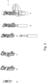
- Figure 1a shows a sensor 2, which consists of a sensor element 3 for detecting any parameter, in particular for contactless detection, with associated connection contacts 4.
- a sensor element 3 for detecting any parameter, in particular for contactless detection
- connection contacts 4 are present, at which a signal representing the detected parameter is available.
- the measuring principle or the application purpose of the entire sensor device 1 there may be only one connection contact or several connection contacts.
- the support body 5 which according to the invention consists of a main body 6 and a receiving body 7.
- This support body 5 is a one-piece component, wherein the main body 6 and the receiving body 7 are connected to one another in such a way that they can be aligned with one another.
- the connection between these two bodies 6, 7 consists of a film hinge.
- Other connecting devices are conceivable.
- the receiving body 7 is aligned in an angled position to the main body 6 after the entire support body 5 has been manufactured.
- the alignment consists of an angle of greater than 10 degrees, preferably 30 degrees, in each case relative to the longitudinal axes that run through the two bodies 6, 7.
- This angled alignment of the receiving body 7 with respect to the main body 6 offers advantages in terms of the ability to mount the sensor 2 on the receiving body 7 and/or advantages in the alignment of the sensor 2 with respect to the component whose parameters are to be measured.
- the main body 6 has at least one guide channel 8.
- This guide channel 8 is present according to the number of connection contacts 4 of the sensor element 3 and is formed by elongated and preferably parallel elevations that protrude from a plate-shaped base of the main body 6.
- the main body 6 also has at least one projection 9 with which the sensor 2 can be secured to the main body 6.
- at least one fixing element 10 is present on the main body 6 and/or, preferably and, at least one fixing element 11 is present on the receiving body 7.
- two fixing elements 10 are present opposite one another on the main body 6 and furthermore two fixing elements 11 are present opposite one another on the receiving body 7.
- Figure 1c shows how the sensor 2 is attached to the receiving body 7. Due to the angled position of the receiving body 7 in relation to the Main body 6 makes it possible to insert the sensor 2, preferably with one of its front sides, into the receiving body 7.
- the receiving body 7 has corresponding guides which are suitable and designed to receive the sensor 2.
- the sensor 2 is flat and straight (right illustration of the Figure1c )), so that after inserting (or alternatively locking) the sensor 2 into the receiving body 7, its connection contacts still protrude from the main body 6.
- connection contacts 2 (and possibly another part of the sensor 2) would already come to rest plane-parallel to the main body 6 in its guide channels 8. If a flat and straight sensor 2 is used, a further bending process is required. In this case, part of the sensor 2 is angled manually or automatically in such a way that another part of the sensor 2 and, above all, the connection contacts 4 also come to rest in the guide channels 8 of the main body 6.
- the entire support body 5 is thus prepared to connect the sensor 2 to a cable 12.
- the cable 12 has at least one line, here two lines 13 (or more than two lines).
- the cable 12 has an outer sheath that surrounds the lines 13.
- the lines 13 also have outer sheaths that each surround an electrical conductor 14.
- end regions of the electrical conductors 14 so that they can be connected to the connection contacts 4.
- the contact area for the connection contacts 4 with the end regions of the electrical conductors 14 is in the area of the guide channels 8 of the main body 6, so that the exact position of the contact area is specified for the subsequent contacting process. This is particularly important for an automated contacting process.
- some of the lines 13, which have been freed from the outer sheath of the cable 12, are in the guide channels 8 of the main body 6, so that in such a case a predeterminable longitudinal alignment of the support body 5 in relation to the cable 12 results. This is also important for the further assembly step of this prepared unit, which is in Figure 1e ) with the housing of the sensor device 11 is important.
- the housing it is conceivable that it is designed in one or more parts, preferably in two parts, and the Figure 1e ) pre-assembled unit is inserted into this housing. If this housing is, for example, two-part, the pre-assembled unit can be inserted into one housing part, preferably into one housing half, and then the second housing part (preferably the second housing half) can be installed. If the housing is designed in one piece, for example, the pre-assembled unit in Figure 1e ) is inserted into the housing, which is open on one side and otherwise closed, and the interior of the housing is filled with appropriate filling material.
- the Figure 1e is placed in a tool (not shown), in particular a two-part or multi-part injection molding tool, the pre-assembled unit being positioned in this tool by the at least one fixing element and/or the at least one fixing element 18 in its position in the tool.
- the plastic injection molding process then takes place, for which the tool, or more precisely its interior, is filled with a plastic material.
- the interior of the tool can be filled with a liquid and then solidifying filler material using only gravity, or alternatively it can be injected into the tool under pressure. In this process, all areas of the pre-assembled unit within the tool are surrounded with plastic material and are thus protected from external stresses such as dirt, effects of moisture and the like.
- the pre-assembled unit is stabilized and can be easily handled during storage, transport and installation as well as later operation.
- the external shape of the overmolding 15 or the housing of the sensor device 1 corresponds to the installation location.
- the bending of the sensor 2 within the elongated housing, in particular the overmolding 15, can be reproduced by a corresponding contouring of the housing, in particular in the area of the sensor 2 (which is no longer visible).
- a bevel at the end of the housing corresponds to the position of the sensor 2, whereby this bevel of the housing is then aligned plane-parallel to the surface of the flat sensor 2.
- FIGS 2a ) to f) basically show the same elements with the same reference numbers and the same process steps as in the Figures 1a ) to f).
- the receiving body 7 is not angled, but is aligned in the same longitudinal axis as the main body 6.
- This pre-assembled unit is advantageously manufactured by Figure 2b ) the receiving body 7 is manufactured at an angle to the main body.
- the straight and flat sensor 2 is then inserted into the receiving body 7 (shown in Figure 2c )) and then the bending of the receiving body 7 in approximately the same plane as the main body 6.
Landscapes
- Physics & Mathematics (AREA)
- General Physics & Mathematics (AREA)
- Transmission And Conversion Of Sensor Element Output (AREA)
- Measuring Temperature Or Quantity Of Heat (AREA)
Description
- Die Erfindung betrifft eine Sensorvorrichtung sowie ein Verfahren zur Herstellung einer Sensorvorrichtung, aufweisend ein Sensorelement, das an einem Tragekörper befestigt ist, wobei das Sensorelement zumindest einen Anschlusskontakt aufweist, der an zumindest einem elektrischen Leiter eines Kabels elektrisch kontaktiert ist, wobei das Sensorelement sowie der Tragekörper in einem Gehäuse aus einem Kunststoffmaterial angeordnet sind, gemäß den jeweiligen Oberbegriffen der beiden unabhängigen Patentansprüche.
- Bezüglich des Verfahrens zur Herstellung einer solchen Sensorvorrichtung ist es bekannt, dass das Sensorelement an einem Tragekörper befestigt wird, wobei der Anschlusskontakt des Sensorelementes mit dem elektrischen Leiter des Kabels elektrisch kontaktiert wird und dann das Sensorelement zusammen mit dem Tragekörper in einem Gehäuse aus einem Kunststoffmaterial angeordnet wird.
- Bei einem aus der
FR 2 864 700 A1 - Bei der
US 5 631 557 A wird ein Magnetsensor bereitgestellt, bei dem ein flexibles Substrat verwendet wird, um eine magnetisch empfindliche Komponente und andere elektronische Komponenten relativ zur Position eines Permanentmagneten zu halten. Ein duroplastisches Material wird als Einkapselungsmittel verwendet, um einen massiven Magnetsensor zu bilden, bei dem die magnetisch empfindliche Komponente, der Permanentmagnet und ein Teil des flexiblen Substrats nach dem Erstarren im duroplastischen Material eingekapselt werden. Ein Teil des flexiblen Substrats erstreckt sich von einem Ende der verfestigten Kapselung, um eine elektrische Verbindung zu anderen Komponenten und Geräten zu ermöglichen. - Aus der
DE 196 40 255 A1 ist ein Verfahren zur Herstellung eines elektronischen Moduls bekannt, bei dem elektronische Bauelemente auf noch nicht vereinzelte Leadframes bestückt und dort angelötet werden, und bei dem anschließend die bestückten Leadframes in zwei Phasen mit Kunststoff umspritzt werden, wobei in einer ersten Spritzphase die Verbindungsstege, mit denen die Leiterbahnen der einzelnen Leadframes untereinander und die Leadframes selbst miteinander verbunden werden, mittels der ersten Spritzgießform span los getrennt werden, und wobei anschließend mindestens ein Extrateil in eine Nische des während der ersten Spritzphase hergestellten Kunststoffkörpers eingelegt wird, wobei daraufhin der Kunststoffkörper in einer zweiten Spritzphase mit einer zweiten Spritzgießform endumspritzt wird. - Beschrieben ist in der
DE 10 2006 030 133 A1 ein Sensor einer elektrischen Moduleinheit sowie ein Verfahren zur Herstellung von Sensor und Moduleinheit. Die Moduleinheit umfasst ein Leitungsgitter mit Leitungssträngen und mindestens einem Flächenbereich, auf den der Rohchip eine integrierte Sensor-Schaltung aufgebracht ist. Ein Isolierkörper ist so gebildet, dass mehrere Leitungsstränge und die integrierte Schaltung eingebettet sind. An einem Grundelement aus Kunststoff sind flache Leiterelemente vorgesehen, die mit einem Steckeranschluss verbunden sind. Die elektrische Moduleinheit wird an dem Grundelement angeordnet, wobei die Leitungsstränge mit den Leiterelementen verbunden werden. Das Leitungsgitter weist ein Loch auf, in das ein Zapfen des Grundelements eingreift. Die elektrische Moduleinheit wird aus einem Streifenelement durch Stanzen und Platzieren des Rohchips hergestellt. In einem Material-Entfernungsschritt werden weitere Teile des Streifenelements entfernt, so dass die elektrische Moduleinheit weiterhin mechanisch mit dem Streifenelement verbunden ist, aber elektrisch mindestens teilweise von diesem so isoliert ist, dass die integrierte Schaltung mindestens zum Teil funktionsfähig ist. - In der
EP 1 672 328 A2 wird ein Magnetfeldsensor, insbesondere ein Drehzahlsensor und/oder Drehrichtungssensor und/oder Positionssensor für den Antriebsstrang eines Kraftfahrzeuges, sowie ein Verfahren zur Herstellung eines derartigen Magnetfeldsensors vorgeschlagen, welcher eine Sensoranordnung mit einem auf ein Magnetfeld reagierenden Sensorelement und gegebenenfalls einen Dauermagneten aufweist, wobei letzterer gemeinsam mit der Sensoranordnung und Teilen von Anschluss-Leiterbahnen mit Kunststoff umhüllt ist und die Leiterbahnen einteilig mit einer Arretierung für den Dauermagnet und die Sensoranordnung als Stanzgitter ausgebildet sind. Das Stanzgitter ist hierbei als dreidimensionale Struktur geformt, welche die Sensoranordnung trägt und gegebenenfalls den Dauermagneten nach Art einer Halterung umgreift. Die Halterung und die Anschluss-Leiterbahnen werden aus einem Blech zunächst als gitterartige Abwicklung ausgestanzt und anschließend zu der Halterung verformt. - Die
WO 2005/080922 A2 betrifft einen Sensorhalter zum Lagern eines Sensorbauteils, insbesondere eines Hall-Sensors, mit einer länglichen Halteeinrichtung, an deren erstem axialen Ende das Sensorbauteil gelagert ist, wobei an deren zweitem axialen Ende ein Anschlusskabel heranführbar ist, dessen Adern mit Anschlüssen des Sensorbauteiles verbindbar sind. Dabei weist die Halteeinrichtung einen Kunststoffträger, an dem das Sensorbauteil gelagert ist, und einen den Kunststoffträger umschließenden metallischen Außenträger, insbesondere eine Metallhülse, auf. - Der Erfindung liegt die Aufgabe zugrunde, eine gegenüber dem Stand der Technik verbesserte Sensorvorrichtung bereitzustellen, die hinsichtlich ihrer Herstellung verbessert ist und besser an den jeweiligen Bauraum nach ihrer Herstellung angepasst ist. Außerdem soll ein Herstellungsverfahren angegeben werden, mit dem eine solche Sensorvorrichtung verbessert automatisiert herstellbar ist.
- Diese Aufgabe ist durch die Merkmale der unabhängigen Patentansprüche gelöst.
- Hinsichtlich der Sensorvorrichtung an sich ist erfindungsgemäß vorgesehen, dass der Tragekörper von einem Hauptkörper sowie einem Aufnahmekörper für das Sensorelement gebildet ist und der Hauptkörper sowie der Aufnahmekörper zueinander ausrichtbar miteinander verbunden sind. Dies hat den Vorteil, dass das Sensorelement an seinem Aufnahmekörper festgelegt werden kann. Danach erfolgt die Ausrichtung des Aufnahmekörpers von einer ersten Position in eine davon abweichende Position in Bezug auf den Hauptkörper, wodurch der Prozess des Festlegens des Sensorelementes an seinem Aufnahmekörper verbessert wird. Denn in der ersten Position des Aufnahmekörpers in Bezug auf den Hauptkörper steht ausreichend Platz zur Verfügung, um das Sensorelement an dem Aufnahmekörper festzulegen. Dieser Festlegeprozess wird dabei nicht von dem Hauptkörper gestört, sodass das Festlegen des Sensorelementes an seinem Aufnahmekörper optimiert in einem automatisierten Prozess ausgeführt werden kann. Erst nachdem das Sensorelement an seinem Aufnahmekörper festgelegt worden ist, wird dieser Aufnahmekörper von seiner bisherigen Position zu dem Hauptkörper in eine davon abweichende Position ebenfalls zu dem Hauptkörper gebracht. Dabei ist es von Vorteil, dass der Aufnahmekörper und der Hauptkörper miteinander verbunden sind, sodass dadurch die Teilevielfalt reduziert und die Bewegung des Aufnahmekörpers von seiner ersten Position in eine davon abweichende Position in Bezug auf den Hauptkörper vorgegeben ist. Vor oder nach dem Ausrichten des Aufnahmekörpers kann das Sensorelement, genauer dessen Anschlusskontakte, mit dem Kabel, genauer mit dessen elektrischen Leitern, elektrisch kontaktiert werden. Dabei ist es von besonderem Vorteil, wenn die elektrische Kontaktierung nach dem Ausrichten des Aufnahmekörpers in Bezug auf den Hauptkörper erfolgt, da in einem solchen Fall die Anschlusskontakte des Sensorelementes flächig an dem Hauptkörper des Tragekörpers anliegen und dieser eine Basis für den anschließenden Kontaktierungsprozess bildet. Eine solche Basis ist beispielsweise dann von besonderem Vorteil, wenn das Ende des elektrischen Leiters mittels eines Löt- oder Verstemmvorgangs mit dem Anschlusskontakt des Sensorelementes erfolgt.
- In Weiterbildung der Erfindung sind der Hauptkörper und der Aufnahmekörper des Tragekörpers durch ein Filmscharnier miteinander verbunden. In diesem Fall sind beispielsweise der Haupt- und der Aufnahmekörper ein einstückiges Bauteil, vorzugsweise aus Kunststoff, weiter vorzugsweise hergestellt durch ein Kunststoffspritzgussverfahren. Durch die Verbindung dieser beiden Körper mittels des Filmscharnieres wird es in einfacher Art und Weise möglich, dass sie zueinander ausrichtbar miteinander verbunden sind. Alternativ dazu ist es an dieser Stelle auch denkbar, dass der Hauptkörper und der Tragekörper nicht miteinander verbunden sind, das heißt, dass es sich hier um zwei einzelne Bauteile handelt.
- Durch das Filmscharnier wird auf besonders einfache Art und Weise gewährleistet, dass der Aufnahmekörper mit dem Sensorelement von seiner ersten Position in die davon abweichende weitere Position in Bezug auf den Hauptkörper gebracht werden kann. Dieser Positionswechsel wird in besonders vorteilhafter Weise dadurch begrenzt, dass zunächst die Anschlusskontakte des Sensorelementes (nachdem es in den Aufnahmekörper eingesetzt und dort festgelegt worden ist) noch nicht an dem Hauptkörper anliegen und erst nach Positionswechsel flächig an dem Hauptkörper anliegen, sodass dadurch auch die Bewegung beim Positionswechsel, das heißt beim Ausrichten, begrenzt wird.
- In Weiterbildung der Erfindung ist vorgesehen, dass vor dem Ausrichtvorgang der Aufnahmekörper für das Sensorelement in einer Montageposition, in der das Sensorelement an dem Aufnahmekörper festgelegt wird, abgewinkelt zu dem Hauptkörper ausgerichtet ist. Diese abgewinkelte Ausrichtung des Aufnahmekörpers in Bezug auf den Hauptkörper kann durch den Herstellvorgang des gesamten Tragekörpers, insbesondere durch die Ausgestaltung des Filmscharnieres, vorgegeben werden. Alternativ dazu ist es denkbar, dass vor dem Ausrichtvorgang der Aufnahmekörper noch nicht abgewinkelt zu dem Hauptkörper ausgerichtet ist. Durch einen entsprechenden Verfahrensschritt wird dann vor der Festlegung des Sensorelementes an dem Aufnahmekörper dieser Aufnahmekörper abgewinkelt in die Montageposition gebracht. Dies bietet den Vorteil, dass der gesamte Tragekörper (bestehend aus Aufnahmekörper und Hauptkörper und gegebenenfalls dem Filmscharnier oder der sonstigen Verbindung untereinander) in einer ersten Formgebung (zum Beispiel längsgestreckt) hergestellt werden kann. Erst danach kann die Abwinklung zum Erzielen der Montageposition des Sensorelementes an dem Aufnahmekörper erfolgen. Dies hat den Vorteil, dass solche längsgesteckten Tragekörper hinsichtlich ihrer Bevorratung und Handhabung einfacher sind als abgewinkelte Tragekörper. Alternativ dazu hat die abgewinkelte Montageposition des Aufnahmekörpers in Bezug auf den Hauptkörper den Vorteil, dass ein weiterer Schritt zum Erzielen der Montageposition entfallen kann und der schon fertige Tragekörper zur weiteren Verarbeitung zur Verfügung steht.
- In Weiterbildung der Erfindung weist der Hauptkörper zumindest einen Führungskanal auf. In besonders vorteilhafter Weise sind so viele Führungskanäle vorhanden, wie das Sensorelement Anschlusskontakte hat. Das bedeutet gleichzeitig, dass so viele Führungskanäle vorhanden sind, wie auch das Kabel Leitungen aufweist. Durch diese Führungskanäle wird gewährleistet, dass einerseits die Anschlusskontakte des Sensorelementes nur oder auch in dem Hauptkörper geführt werden. Diese Führung erfolgt insbesondere während der Ausrichtung der beiden Körper zueinander, aber auch nach deren Ausrichtung zueinander. Weiterhin ist von Vorteil, dass, nachdem sich die Anschlusskontakte des Sensorelementes in den jeweiligen Führungskanälen befinden, auch die Enden der Leitungen das Kabels, insbesondere mit dessen freigelegten elektrischen Leitern, in den Führungskanälen angeordnet werden können. Eine solche Führung bzw. lagegenaue Anordnung der Anschlusskontakte bzw. der Enden der elektrischen Leiter an dem Tragekörper, vorzugsweise an dem Hauptkörper, ist deshalb besonders wichtig, da der Vorgang des elektrischen Kontaktierens der Anschlusskontakte mit den elektrischen Leitern ebenfalls automatisiert erfolgen soll. Durch die Führungskanäle an dem Hauptkörper wird somit sichergestellt, dass dort die Anschlusskontakte des Sensorelementes liegen und anschließend die elektrischen Leiter über die Anschlusskontakte gelegt werden können (oder umgekehrt). Danach ist es automatisiert möglich, in diesem Kontaktbereich den elektrischen Kontakt zwischen den Anschlusskontakten des Sensorelementes und den Enden der elektrischen Leiter des Kabels durchzuführen. Dies kann beispielsweise durch Verlöten, Verschweißen, Verstemmen, Vercrimpen, elektrisch Verkleben oder dergleichen erfolgen. In diesem Zusammenhang ist es noch wichtig, darauf hinzuweisen, dass für den Fall, dass ein Verbindungsprozess mit hohen Temperaturen gewählt ist (wie zum Beispiel ein Löt- oder Schweißvorgang), das Material des Tragekörpers, insbesondere dessen Hauptkörpers, entsprechend hitzebeständig ausgebildet ist.
- In Weiterbildung der Erfindung weist der Hauptkörper zumindest ein Fixierelement und/oder zumindest einen Vorsprung auf. Das jeweils vorhandene Fixierelement bzw. der jeweils vorhandene Vorsprung kann unterschiedliche Aufgaben haben. Zum einen kann mit einem solchen Fixierelement (ausgebildet zunächst als Vorsprung) eine weitere Lagefixierung der Leitung, des Kontaktbereiches oder der Anschlusskontakte des Sensorelementes an dem Hauptkörper erfolgen. Dies erfolgt in vorteilhafter Weise durch einen Umformvorgang des zumindest einen Vorsprunges, wie zum Beispiel ein Warm- oder Kaltverprägen. Alternativ dazu kann das Fixierelement als Rastelement ausgebildet sein, sodass die elektrische Leitung, der Kontaktbereich und/oder der Anschlusskontakt des Sensorelementes mittels dieses Rastelements an dem Hauptkörper festgelegt werden. Alternativ oder ergänzend zu dem Fixierelement, mit dem die Leitung des Kabels und/oder der Kontaktbereich und/oder der Anschlusskontakt des Sensorelementes an dem Hauptkörper festgelegt wird, kann ein solches zumindest eine Fixierelement dafür vorgesehen sein, dass der gesamte Tragekörper in ein Werkzeug eingesetzt und dort mit diesem Fixierelement in seiner Lage positioniert wird, wenn das Gehäuse der gesamten Sensorvorrichtung montiert wird. Dabei ist es denkbar, dass das Gehäuse als separates Bauteil schon vorgefertigt ist und der gesamte Tragekörper nach seiner Montage in diesem Gehäuse angeordnet wird. In einem solchen Fall weist auch das Gehäuse der Sensorvorrichtung mit dem Fixierelement des Tragekörpers korrespondierende Elemente auf. Wenn das Gehäuse der Sensorvorrichtung als eine Umspritzung gebildet wird, ist das zumindest eine Fixierelement des Hauptkörpers dazu geeignet und ausgebildet, diesen in einem Werkzeug festzulegen, sodass der gesamte vormontierte Tragekörper mit dem Sensorelement in dem Werkzeug in seiner Sollposition für den nachfolgenden Umspritzvorgang mit einem Kunststoffmaterial positioniert wird.
- In Weiterbildung der Erfindung weist der Aufnahmekörper für das Sensorelement zumindest ein Fixierelement auf. Auch hier kann ein solches Fixierelement verschiedene Funktionen haben. Zum einen dient ein solches Fixierelement dazu, das Sensorelement an seinem Aufnahmekörper festzulegen. Dieser Festlegevorgang kann ebenfalls durch Verprägen, Verstemmen, Verrasten oder dergleichen erfolgen, wozu das Fixierelement oder auch mehrere Fixierelemente entsprechend ausgebildet ist/sind. Alternativ oder ergänzend dazu kann ein solches zumindest eine Fixierelement auch, wie schon bei dem Hauptkörper, dazu geeignet und ausgebildet sein, den vormontierten Tragekörper in dem Gehäuse der Sensorvorrichtung festzulegen. Diesbezüglich gilt für das Fixierelement des Aufnahmekörpers das gleiche wie für das Fixierelement des Hauptkörpers. Das zumindest eine Fixierelement zur Festlegung des vormontierten Tragekörpers in dem Gehäuse der Sensorvorrichtung ist dabei entweder nur an dem Hauptkörper oder nur an dem Aufnahmekörper oder an beiden entweder einfach oder mehrfach, vorzugsweise jeweils zweifach, vorhanden.
- Von besonderem Vorteil ist es, wenn das Gehäuse der Sensorvorrichtung von einer Umspritzung aus einem Kunststoffmaterial gebildet ist. Zum einen lässt sich durch entsprechende Formgebung eines Werkzeuges die Form des Gehäuses der Sensorvorrichtung flexibel anpassen, sodass durch diese Formgebung eine individuelle Anpassung des Gehäuses der Sensorvorrichtung an deren Bauraum erfolgen kann. Ein weiterer Vorteil ist darin zu sehen, dass mit der Umspritzung die beteiligten Elemente (Tragekörper mit Hauptkörper und Aufnahmekörper sowie Sensorelemente und Kabelende) zusätzlich in ihrer Lage zueinander fixiert und diese ganze Einheit stabil ausgebildet werden kann. Schließlich ist noch der Vorteil zu nennen, dass durch die Umspritzung (bzw. durch die Bildung eines Gehäuses auch in anderer Form) die beteiligten Bauelemente vor äußeren Einflüssen geschützt untergebracht sind. Dies ist bei der Umspritzung dann von besonderem Vorteil, wenn das Material des Gehäuses auf das Material des Außenmantels des Kabels abgestimmt wird, sodass dieser Bereich eine innige Verbindung eingeht und damit gewährleistet ist, dass keine Feuchtigkeit oder Wasser oder Verunreinigungen in den Innenbereich der Sensorvorrichtung eindringen kann.
- Das Sensorelement an sich kann ein beliebiges Sensorelement zur berührungslosen Erfassung von Parametern sein. Beispielhaft ist hier ein kapazitiv oder induktiv wirkendes Sensorelement genannt, welches beispielsweise für die Ermittlung von Umdrehungen eines Bauteiles ausgebildet ist. Die Erfassung solcher Parameter erfolgt entweder durch das Sensorelement alleine oder mit mit dem Sensorelement zusammenwirkenden Hilfsmitteln. Solche Hilfsmittel sind zum Beispiel bei einem Sensorelement, bei dem es sich um ein Hall-Element handelt, ein Magnet, der an dem zu erfassenden Bauteil angebracht ist. Die vorstehende Erwähnung von Messprinzipien und Sensorelementen ist nur beispielhaft und nicht abschließend.
- Das erfindungsgemäße Verfahren zur Herstellung einer Sensorvorrichtung sowie eine beispielhafte Ausgestaltung einer solchen Sensorvorrichtung ist anhand der
Figuren 1 und2 erläutert. - In
Figur 1 , insbesondere inFigur 1f ), ist, soweit im Einzelnen dargestellt, eine Sensorvorrichtung 1 gezeigt. -
Figur 1a ) zeigt einen Sensor 2, der aus einem Sensorelement 3 zur Erfassung eines beliebigen Parameters, insbesondere zur berührungslosen Erfassung, mit zugehörigen Anschlusskontakten 4 besteht. In diesem Fall sind zwei Anschlusskontakte 4 vorhanden, an denen ein den erfassten Parameter repräsentierendes Signal zur Verfügung steht. Je nach Ausgestaltung des Sensors 2, des Messprinzipes bzw. des Anwendungszweckes der gesamten Sensorvorrichtung 1 kann auch nur ein Anschlusskontakt oder können auch mehrere Anschlusskontakte vorhanden sein. - In
Figur 1b ) ist der Tragekörper 5 gezeigt, der erfindungsgemäß aus einem Hauptkörper 6 und einem Aufnahmekörper 7 besteht. Dieser Tragekörper 5 ist ein einstückiges Bauteil, wobei der Hauptkörper 6 sowie der Aufnahmekörper 7 zueinander ausrichtbar miteinander verbunden sind. In diesem Fall besteht die Verbindung zwischen diesen beiden Körpern 6, 7 aus einem Filmscharnier. Andere Verbindungseinrichtungen sind denkbar. In diesem Fall ist der Aufnahmekörper 7 in einer abgewinkelten Position zu dem Hauptkörper 6 nach der Herstellung des gesamten Tragekörpers 5 ausgerichtet. In einem Beispielfall besteht die Ausrichtung aus einer Abwinklung mit einem Winkel größer 10 Grad, vorzugsweise 30 Grad, jeweils bezogen auf die Längsachsen, die durch die beiden Körper 6, 7 verlaufen. Diese abgewinkelte Ausrichtung des Aufnahmekörpers 7 in Bezug auf den Hauptkörper 6 bietet Vorteile hinsichtlich der Montierbarkeit des Sensors 2 an dem Aufnahmekörper 7 und/oder Vorteile bei der Ausrichtung des Sensors 2 in Bezug auf das Bauteil, dessen Parameter gemessen werden soll. - Weiterhin ist in
Figur 1b ) erkennbar, dass der Hauptkörper 6 zumindest einen Führungskanal 8 aufweist. Dieser Führungskanal 8 ist entsprechend der Anzahl der Anschlusskontakte 4 des Sensorelementes 3 vorhanden und gebildet durch länglich gestaltete und vorzugsweise parallel zueinander verlaufende Erhebungen, die von einer plattenförmigen Basis des Hauptkörpers 6 abstehen. Weiterhin weist der Hauptkörper 6 zumindest einen Vorsprung 9 auf, mit dem der Sensor 2 an dem Hauptkörper 6 festgelegt werden kann. Weiterhin sind an dem Hauptkörper 6 zumindest ein Fixierelement 10 undloder, vorzugsweise und, an dem Aufnahmekörper 7 zumindest ein Fixierelement 11 vorhanden. Bei einer besonders vorteilhaften Ausgestaltung des gesamten Tragekörpers 5 sind zwei Fixierelemente 10 einander gegenüberliegend an dem Hauptkörper 6 und weiterhin zwei einander gegenüberliegende Fixierelemente 11 an dem Aufnahmekörper 7 vorhanden. - In
Figur 1c ) ist gezeigt, wie der Sensor 2 an dem Aufnahmekörper 7 festgelegt wird. Durch die abgewinkelte Position des Aufnahmekörpers 7 in Bezug auf den Hauptkörper 6 wird es möglich, den Sensor 2, vorzugsweise mit seiner einen Stirnseite, in den Aufnahmekörper 7 einzuschieben. In diesem Fall hat der Aufnahmekörper 7 entsprechende Führungen, die dazu geeignet und ausgebildet sind, den Sensor 2 aufzunehmen. In diesem Fall ist der Sensor 2 flächig gerade ausgebildet (rechte Darstellung derFigur1c )), sodass nach dem Einschieben (oder alternativ Verrasten) des Sensors 2 an dem Aufnahmekörper 7 dessen Anschlusskontakte noch von dem Hauptkörper 6 abstehen. Würde eine abgewinkelte Ausführung des Sensors 2 (sieheFigur 1c ) in der linken Darstellung) verwendet, und wäre diese Abwinklung genauso ausgerichtet wie der Aufnahmekörper 7 zu dem Hauptkörper 6 ausgerichtet ist, dann würden die Anschlusskontakte 2 (und gegebenenfalls ein weiterer Teil des Sensors 2) schon planparallel zu dem Hauptkörper 6 in dessen Führungskanälen 8 zur Anlage kommen. Wird ein flächig und sich gerade erstreckender Sensor 2 eingesetzt, ist noch ein weiterer Abwinklungsvorgang erforderlich. In diesem Fall wird von Hand oder automatisiert ein Teil des Sensors 2 so abgewinkelt, dass jetzt auch ein weiterer Teil des Sensors 2 und vor allen Dingen auch die Anschlusskontakte 4 in den Führungskanälen 8 des Hauptkörpers 6 zur Anlage kommen. - In
Figur 1d ) ist nun gezeigt, dass der Sensor 2 abgewinkelt war oder abgewinkelt worden ist und danach an seinem Aufnahmekörper 7 festgelegt wurde. Damit ist der gesamte Tragekörper 5 vorbereitet, um den Sensor 2 mit einem Kabel 12 zu verbinden. Das Kabel 12 weist zumindest eine Leitung, hier zwei Leitungen 13 (oder auch mehr als zwei Leitungen) auf. Das Kabel 12 weist einen Außenmantel auf, der die Leitungen 13 umgibt. Die Leitungen 13 weisen ebenfalls Außenmäntel auf, die jeweils einen elektrischen Leiter 14 umgeben. Zur Verbindung des Kabels 12 mit dem Sensor 2 ist ein Stück des Außenmantels des Kabels 12 entfernt und auch ein Stück des Außenmantels der Leitungen 13 entfernt worden. Somit liegen in entsprechender Länge Endbereiche der elektrischen Leiter 14 vor, damit diese mit den Anschlusskontakten 4 verbunden werden können. Der Kontaktbereich für die Anschlusskontakte 4 mit den Endbereichen der elektrischen Leiter 14 liegt im Bereich der Führungskanäle 8 des Hauptkörpers 6, sodass für den anschließenden Kontaktierungsvorgang die genaue Position des Kontaktbereiches vorgegeben ist. Dies ist besonders wichtig für einen automatisierten Kontaktierungsvorgang. Außerdem befindet sich ein Teil der Leitungen 13, die von dem Außenmantel des Kabels 12 befreit worden sind, in den Führungskanälen 8 des Hauptkörpers 6, sodass sich in einem solchen Fall eine vorgebbare längsgestreckte Ausrichtung des Tragekörpers 5 in Bezug auf das Kabel 12 ergibt. Auch dies ist für den weiteren Montageschritt dieser vorbereiteten Einheit, die inFigur 1e ) gezeigt ist, mit dem Gehäuse der Sensorvorrichtung 11 wichtig. - Bezüglich des Gehäuses ist es denkbar, dass dieses einteilig oder mehrteilig, vorzugsweise zweiteilig gestaltet ist, und die in
Figur 1e ) vormontierte Einheit in dieses Gehäuse eingesetzt wird. Ist dieses Gehäuse beispielsweise zweiteilig, kann die vormontierte Einheit in den einen Gehäuseteil, vorzugsweise in die eine Gehäusehälfte, eingesetzt und danach der zweite Gehäuseteil (vorzugsweise die zweite Gehäusehälfte) montiert werden. Ist das Gehäuse einteilig ausgestaltet, kann zum Beispiel die inFigur 1e ) gezeigte vormontierte Einheit in das Gehäuse, welches an einer Seite offen und ansonsten geschlossen ist, eingeführt und das Innere des Gehäuses mit entsprechendem Füllmaterial vergossen werden. - Von besonderem Vorteil sowohl hinsichtlich der Herstellung des Gehäuses als auch während des Betriebes der Sensorvorrichtung 1 ist es, wenn das Gehäuse von einer Umspritzung aus einem Kunststoffmaterial gebildet ist. Dies ist in
Figur 1f ) gezeigt. Dort ist erkennbar, dass die inFigur 1e ) gezeigte vormontierte Einheit mit einer Umspritzung 15 versehen worden ist. Je nach Einbauraum der Sensorvorrichtung 1 kann dabei auch ein Befestigungselement, insbesondere ein ringförmiges Befestigungselement 16 mit einer zugänglichen Durchführungsöffnung, von der Umspritzung 15 festgelegt werden. Um die Umspritzung 15 zu realisieren, wird die inFigur 1e ) gezeigte vormontierte Einheit in einem nicht dargestellten Werkzeug, insbesondere einem zwei- oder mehrteiligen Spritzgusswerkzeug eingelegt, wobei die vormontierte Einheit in diesem Werkzeug durch das zumindest eine Fixierelement undloder das zumindest eine Fixierelement 18 in seiner Lage in dem Werkzeug positioniert wird. Anschließend erfolgt der Kunststoffspritzgussvorgang, wozu das Werkzeug, genauer dessen Innenraum, mit einem Kunststoffmaterial aufgefüllt wird. Bei diesem Spritzgussvorgang kann das Innere des Werkzeuges nur mit der Schwerkraft mit einem flüssigen und anschließend erstarrenden Füllmaterial aufgefüllt werden oder alternativ unter Druck in das Werkzeug eingespritzt werden. Dabei werden innerhalb des Werkzeuges alle Bereiche der vormontierten Einheit mit Kunststoffmaterial umgeben und sind somit vor äußeren Beanspruchungen wie Verschmutzungen, Einwirkungen durch Feuchtigkeit und dergleichen geschützt. Außerdem wird die vormontierte Einheit stabilisiert und kann ohne weiteres bei der Lagerung, dem Transport und dem Einbau sowie dem späteren Betrieb gehandhabt werden. Die äußere Formgebung der Umspritzung 15 bzw. des Gehäuses der Sensorvorrichtung 1 entspricht dabei dem Einbauort. Die Abwinklung des Sensors 2 innerhalb des sich länglich erstreckenden Gehäuses, insbesondere der Umspritzung 15, kann durch eine entsprechende Konturgebung des Gehäuses, insbesondere im Bereich des Sensors 2 (der nicht mehr sichtbar ist) wiedergegeben werden. In besonders vorteilhafter Weise entspricht dann beispielsweise eine Abschrägung am Ende des Gehäuses der Lage des Sensors 2, wobei dann diese Abschrägung des Gehäuses planparallel zu der Oberfläche des flächig ausgebildeten Sensors 2 ausgerichtet ist. - An dieser Stelle sei erwähnt, dass in der
Figur 1 ein rechteckförmiger und flächig gestalteter Sensor 2 gezeigt ist. Die Erfindung ist jedoch nicht auf eine solche Bauform beschränkt, sodass auch andere geometrische Bauformen eines solchen Sensors in Betracht kommen. - In den
Figuren 2a ) bis f) sind prinzipiell die gleichen Elemente mit gleichen Bezugsziffern und die gleichen Verfahrensschritte gezeigt, die auch in denFiguren 1a ) bis f) gezeigt und beschrieben worden sind. Der einzige Unterschied ist darin zu sehen, dass in der vormontierten Einheit, gezeigt inFigur 2e ), der Aufnahmekörper 7 nicht abgewinkelt, sondern in der gleichen Längsachse wie der Hauptkörper 6, ausgerichtet ist. Diese vormontierte Einheit wird in vorteilhafter Weise dadurch hergestellt, dass gemäßFigur 2b ) der Aufnahmekörper 7 abgewinkelt zu dem Hauptkörper ausgerichtet hergestellt wird. Anschließend erfolgt das Einsetzen des geraden und flächig gestalteten Sensors 2 in den Aufnahmekörper 7 (dargestellt inFigur 2c )) und danach die Abwinklung des Aufnahmekörpers 7 in etwa in die gleiche Ebene, in der sich der Hauptkörper 6 befindet. Danach können, wie auch schon zuFigur 1 geschrieben, die Enden der elektrischen Leiter 14 mit den Anschlusskontakten 4 des Sensors 2 verbunden werden, sodass sich letztendlich dadurch die vormontierte Einheit gemäßFigur 2e ) ergibt. An dieser Stelle ist es auch noch denkbar, bei dem inFigur 2c ) gezeigten Schritt nicht einen sich gerade und flächig erstreckenden Sensor 2 einzusetzen, sondern auch schon einen abgewinkelt (analog zuFigur 1c ), linke Darstellung) gestalteten Sensor 2 zu verwenden. In einem solchen Fall wird dann in dem Schritt, wie er beim Übergang vonFigur 2c ) hin zuFigur 2d ) erfolgt, nicht nur der Aufnahmekörper 7 in eine andere Position zu dem Hauptkörper 6 gebracht, sondern dabei auch der vorher abgewinkelt gestaltete Sensor 2 erneut abgewinkelt, um in eine längsgestreckte Ausrichtung gebracht zu werden. Dies kann beispielsweise dann erforderlich sein, wenn sichergestellt werden soll, dass die Anschlusskontakte 4 des Sensors 2 unter Vorspannung in den Führungskanälen 8 des Hauptkörpers 6 zur Anlage kommen sollen. -
- 1.
- Sensorvorrichtung
- 2.
- Sensor
- 3.
- Sensorelement
- 4.
- Anschlusskontakte
- 5.
- Tragekörper
- 6.
- Hauptkörper
- 7.
- Aufnahmekörper
- 8.
- Führungskanal
- 9.
- Vorsprung
- 10.
- Fixierelement
- 11.
- Fixierelement
- 12.
- Kabel
- 13.
- Leitung
- 14.
- Elektrischer Leiter
- 15.
- Umspritzung
- 16.
- Befestigungselement
Claims (9)
- Sensorvorrichtung (1), aufweisend einen Sensor (2), der aus einem Sensorelement (3) zur Erfassung eines Parameters und zumindest einem zugehörigen Anschlusskontakt (4) besteht, einen einstückigen Tragekörper (5), der aus einem Hauptkörper (6) und einem Aufnahmekörper (7) für das Sensorelement (3) besteht, ein Gehäuse (15) aus einem Kunststoffmaterial, und ein Kabel (12) mit zumindest einem elektrischen Leiter (13), wobei das Sensorelement (3) an dem Aufnahmekörper (7) befestigt ist, wobei der zumindest eine Anschlusskontakt (4) des Sensors (2) mit einem Endbereich des zumindest einen elektrischen Leiters (14) des Kabels (12) verbunden und elektrisch kontaktiert ist, wobei der Sensor (2) sowie der Tragekörper (5) in dem Gehäuse angeordnet sind, wobei der Hauptkörper (6) und der Aufnahmekörper (7) in verschiedenen Positionen zueinander ausrichtbar sind, wobei nach der Montage des Sensors (2) der Hauptkörper (6) und der Aufnahmekörper (7) in einer der Positionen zueinander ausgerichtet und miteinander verbunden sind, wobei das Gehäuse (15) bei einer Umspritzung aus einem Kunststoffmaterial um die aus dem Tragekörper (5), dem Sensor (2) und einem Endbereich des Kabels (12) bestehende vormontierte Einheit gebildet ist.
- Sensorvorrichtung (1) nach Anspruch 1, dadurch gekennzeichnet, dass der Hauptkörper (6) und der Aufnahmekörper (7) durch ein Filmscharnier miteinander verbunden sind.
- Sensorvorrichtung (1) nach Anspruch 1 oder 2, dadurch gekennzeichnet, dass der Aufnahmekörper (7) für das Sensorelement (2) in einer Montageposition, in der das Sensorelement (2) an dem Aufnahmekörper (7) festgelegt wird, abgewinkelt zu dem Hauptkörper (6) ausgerichtet ist.
- Sensorvorrichtung (1) nach einem der vorhergehenden Ansprüche, dadurch gekennzeichnet, dass der Hauptkörper (6) zumindest einen Führungskanal (8) aufweist.
- Sensorvorrichtung (1) nach einem der vorhergehenden Ansprüche, dadurch gekennzeichnet, dass der Hauptkörper (6) zumindest einen Vorsprung (9) und/oder ein Fixierelement (10) aufweist.
- Sensorvorrichtung (1) nach einem der vorhergehenden Ansprüche, dadurch gekennzeichnet, dass der Aufnahmekörper (7) zumindest ein Fixierelement (11) aufweist.
- Verfahren zur Herstellung einer Sensorvorrichtung (1), wobei die Sensorvorrichtung (1) einen Sensor (2), der aus einem Sensorelement (3) zur Erfassung eines Parameters und zumindest einem zugehörigen Anschlusskontakt (4) besteht, einen einsückigen Tragekörper (5), der aus einem Hauptkörper (6) und einem Aufnahmekörper (7) für das Sensorelement (3) besteht, ein Gehäuse (15) aus einem Kunststoffmaterial und ein Kabel (12) mit zumindest einem elektrischen Leiter (13) aufweist, wobei das Sensorelement (3) an dem Tragekörper (5) befestigt ist, wobei der zumindest eine Anschlusskontakt (4) des Sensors (2) mit einem Endbereich des zumindest einen elektrischen Leiters (14) des Kabels (12) verbunden und elektrisch kontaktiert ist, wobei der Sensor (2) sowie der Tragekörper (5) in dem Gehäuse angeordnet sind, gekennzeichnet durch die Schritte: Einsetzen des Sensorelementes (3) in den Aufnahmekörper (7), danach Ausrichten des Hauptkörpers (6) und des Aufnahmekörpers (7) miteinander, wobei der Hauptkörper (6) und der Aufnahmekörper (7) miteinander ausrichtbar sind, danach Verbindung des Endbereiches des zumindest einen elektrischen Leiters (14) des Kabels (12) mit dem zumindest einen zugehörigen Anschlusskontakt (4), und danach Bildung des Gehäuses (15) bei einer Umspritzung aus einem Kunststoffmaterial um die aus dem Tragekörper (5), dem Sensor (2) und einem Endbereich des Kabels (12) bestehende vormontierte Einheit.
- Verfahren nach Anspruch 7, dadurch gekennzeichnet, dass das Sensorelement (2) durch Umformen zumindest eines Fixierelementes des Aufnahmekörpers (7) an diesem befestigt wird.
- Verfahren nach Anspruch 7 oder 8, dadurch gekennzeichnet, dass nach der erfolgten Ausrichtung der zumindest eine Anschlusskontakt (4) des Sensors (2) mit dem zumindest einen elektrischen Leiter (14) des Kabels (12) elektrisch kontaktiert wird.
Applications Claiming Priority (1)
| Application Number | Priority Date | Filing Date | Title |
|---|---|---|---|
| DE102011089365 | 2011-12-21 |
Publications (3)
| Publication Number | Publication Date |
|---|---|
| EP2607859A2 EP2607859A2 (de) | 2013-06-26 |
| EP2607859A3 EP2607859A3 (de) | 2017-11-15 |
| EP2607859B1 true EP2607859B1 (de) | 2024-08-28 |
Family
ID=47594422
Family Applications (1)
| Application Number | Title | Priority Date | Filing Date |
|---|---|---|---|
| EP12199001.4A Active EP2607859B1 (de) | 2011-12-21 | 2012-12-21 | Tragekörper zur Aufnahme eines Sensors |
Country Status (2)
| Country | Link |
|---|---|
| EP (1) | EP2607859B1 (de) |
| DE (1) | DE102012224244A1 (de) |
Families Citing this family (2)
| Publication number | Priority date | Publication date | Assignee | Title |
|---|---|---|---|---|
| DE102014013312A1 (de) * | 2014-09-08 | 2016-03-10 | Wabco Gmbh | Träger für ein Sensorelement, Bauteilgruppe und Drehzahlsensor |
| DE102016210519B4 (de) * | 2016-06-14 | 2020-09-10 | Robert Bosch Gmbh | Sensoranordnung und Verfahren zur Herstellung einer Sensoranordnung |
Citations (4)
| Publication number | Priority date | Publication date | Assignee | Title |
|---|---|---|---|---|
| DE19640255A1 (de) * | 1996-09-30 | 1998-04-02 | Siemens Ag | Verfahren zur Herstellung eines elektronischen Moduls mit einem kunststoffumspritzten Leadframe |
| WO2005080922A2 (de) * | 2004-02-24 | 2005-09-01 | Prettl, Rolf | Sensorhalter und verfahren zu dessen herstellung |
| EP1672328A2 (de) * | 2004-12-20 | 2006-06-21 | Robert Bosch Gmbh | Magnetfeldsensor |
| DE102006030133A1 (de) * | 2005-06-29 | 2007-02-08 | Ab Elektronik Gmbh | Sensor mit Leadframe und Herstellungsverfahren hierfür |
Family Cites Families (2)
| Publication number | Priority date | Publication date | Assignee | Title |
|---|---|---|---|---|
| US5631557A (en) * | 1996-02-16 | 1997-05-20 | Honeywell Inc. | Magnetic sensor with encapsulated magnetically sensitive component and magnet |
| FR2864700A1 (fr) * | 2003-12-31 | 2005-07-01 | Siemens Vdo Automotive | Procede d'enrobage d'une unite electronique d'un capteur et capteur correspondant |
-
2012
- 2012-12-21 EP EP12199001.4A patent/EP2607859B1/de active Active
- 2012-12-21 DE DE102012224244A patent/DE102012224244A1/de not_active Ceased
Patent Citations (4)
| Publication number | Priority date | Publication date | Assignee | Title |
|---|---|---|---|---|
| DE19640255A1 (de) * | 1996-09-30 | 1998-04-02 | Siemens Ag | Verfahren zur Herstellung eines elektronischen Moduls mit einem kunststoffumspritzten Leadframe |
| WO2005080922A2 (de) * | 2004-02-24 | 2005-09-01 | Prettl, Rolf | Sensorhalter und verfahren zu dessen herstellung |
| EP1672328A2 (de) * | 2004-12-20 | 2006-06-21 | Robert Bosch Gmbh | Magnetfeldsensor |
| DE102006030133A1 (de) * | 2005-06-29 | 2007-02-08 | Ab Elektronik Gmbh | Sensor mit Leadframe und Herstellungsverfahren hierfür |
Also Published As
| Publication number | Publication date |
|---|---|
| EP2607859A3 (de) | 2017-11-15 |
| EP2607859A2 (de) | 2013-06-26 |
| DE102012224244A1 (de) | 2013-06-27 |
Similar Documents
| Publication | Publication Date | Title |
|---|---|---|
| AT12838U1 (de) | Sensoradapterschaltungsgehäuseaufbau und verfahren zu dessen herstellung | |
| DE102018210892B4 (de) | Steckverbindungselement für ein Kraftfahrzeug und Verfahren zum Herstellen eines solchen Steckverbindungselements | |
| DE102008018199A1 (de) | Elektrische Baugruppe mit einem Stanzgitter, elektrischen Bauelementen und einer Füllmasse | |
| EP1199913A2 (de) | Verfahren zur Herstellung von Leiterfolie-Trägergehäuse-Einheiten | |
| EP2449581B1 (de) | Verfahren zur herstellung eines elektronischen bauteils | |
| DE102012222679A1 (de) | Verfahren zur Herstellung eines Schaltmoduls und eines zugehörigen Gittermoduls sowie ein zugehöriges Gittermodul und korrespondierende elektronische Baugruppe | |
| DE102016210532B4 (de) | Sensoranordnung | |
| DE102005009441A1 (de) | Steckverbinder mit einer Crimp-Abdichtung und/oder einer Kabelhalterung | |
| WO2018041441A1 (de) | Kraftfahrzeugtürgriffanordnung mit abgedichtetem elektronikbauraum | |
| WO2018041447A1 (de) | Kraftfahrzeugtürgriffanordnung mit montageerleichterung | |
| WO2010142475A1 (de) | Verfahren zur herstellung elektronischer bauteile | |
| EP2265102A1 (de) | Sensoraufbau ohne Gehäuse | |
| DE102005009442A1 (de) | Steckverbinder mit einer Crimp-Abdichtung und/oder einer Kabelhalterung | |
| DE102011003239B4 (de) | Sensormodul, Montageelement und Verfahren zum Herstellen eines Sensormoduls | |
| EP3109953A1 (de) | Kupplungsteil für eine elektrische leitung | |
| DE102008031085A1 (de) | Kupplungsteil für eine elektrische Leitung | |
| DE102017222681A1 (de) | Sensorkopf und Verfahren zur Herstellung eines Sensorkopfes | |
| DE102012224244A1 (de) | Tragekörper zur Aufnahme von einem Sensor | |
| WO2018006894A1 (de) | Verfahren zur herstellung eines elektrokomponententrägers für automobile anwendungen | |
| DE102015016467A1 (de) | Kraftfahrzeugtürgriff mit integrierter Elektronikbaugruppe | |
| DE102016210550B4 (de) | Sensorvorrichtung und Verfahren zur Herstellung einer Sensorvorrichtung | |
| DE102004033284A1 (de) | Verfahren und Vorrichtung zur Herstellung einer elektrischen und mechanischen Verbindung sowie eines Kunststoffvergusses von Teilen | |
| DE202009004984U1 (de) | Kraftfahrzeugschloss bestehend aus mechanischen und elektrischen, elektromotorischen und/oder elektronischen Bauteilen | |
| DE102016210519B4 (de) | Sensoranordnung und Verfahren zur Herstellung einer Sensoranordnung | |
| WO2018041448A1 (de) | Kraftfahrzeugtürgriffanordnung mit antenne |
Legal Events
| Date | Code | Title | Description |
|---|---|---|---|
| AK | Designated contracting states |
Kind code of ref document: A2 Designated state(s): AL AT BE BG CH CY CZ DE DK EE ES FI FR GB GR HR HU IE IS IT LI LT LU LV MC MK MT NL NO PL PT RO RS SE SI SK SM TR |
|
| AX | Request for extension of the european patent |
Extension state: BA ME |
|
| PUAI | Public reference made under article 153(3) epc to a published international application that has entered the european phase |
Free format text: ORIGINAL CODE: 0009012 |
|
| PUAL | Search report despatched |
Free format text: ORIGINAL CODE: 0009013 |
|
| AK | Designated contracting states |
Kind code of ref document: A3 Designated state(s): AL AT BE BG CH CY CZ DE DK EE ES FI FR GB GR HR HU IE IS IT LI LT LU LV MC MK MT NL NO PL PT RO RS SE SI SK SM TR |
|
| AX | Request for extension of the european patent |
Extension state: BA ME |
|
| RIC1 | Information provided on ipc code assigned before grant |
Ipc: G01D 11/24 20060101ALI20171011BHEP Ipc: G01D 11/30 20060101AFI20171011BHEP |
|
| STAA | Information on the status of an ep patent application or granted ep patent |
Free format text: STATUS: REQUEST FOR EXAMINATION WAS MADE |
|
| 17P | Request for examination filed |
Effective date: 20180515 |
|
| RBV | Designated contracting states (corrected) |
Designated state(s): AL AT BE BG CH CY CZ DE DK EE ES FI FR GB GR HR HU IE IS IT LI LT LU LV MC MK MT NL NO PL PT RO RS SE SI SK SM TR |
|
| STAA | Information on the status of an ep patent application or granted ep patent |
Free format text: STATUS: EXAMINATION IS IN PROGRESS |
|
| 17Q | First examination report despatched |
Effective date: 20200214 |
|
| GRAP | Despatch of communication of intention to grant a patent |
Free format text: ORIGINAL CODE: EPIDOSNIGR1 |
|
| STAA | Information on the status of an ep patent application or granted ep patent |
Free format text: STATUS: GRANT OF PATENT IS INTENDED |
|
| INTG | Intention to grant announced |
Effective date: 20240607 |
|
| GRAS | Grant fee paid |
Free format text: ORIGINAL CODE: EPIDOSNIGR3 |
|
| GRAA | (expected) grant |
Free format text: ORIGINAL CODE: 0009210 |
|
| STAA | Information on the status of an ep patent application or granted ep patent |
Free format text: STATUS: THE PATENT HAS BEEN GRANTED |
|
| AK | Designated contracting states |
Kind code of ref document: B1 Designated state(s): AL AT BE BG CH CY CZ DE DK EE ES FI FR GB GR HR HU IE IS IT LI LT LU LV MC MK MT NL NO PL PT RO RS SE SI SK SM TR |
|
| REG | Reference to a national code |
Ref country code: GB Ref legal event code: FG4D Free format text: NOT ENGLISH |
|
| REG | Reference to a national code |
Ref country code: CH Ref legal event code: EP |
|
| REG | Reference to a national code |
Ref country code: DE Ref legal event code: R096 Ref document number: 502012017276 Country of ref document: DE |
|
| REG | Reference to a national code |
Ref country code: IE Ref legal event code: FG4D Free format text: LANGUAGE OF EP DOCUMENT: GERMAN |
|
| REG | Reference to a national code |
Ref country code: LT Ref legal event code: MG9D |
|
| PG25 | Lapsed in a contracting state [announced via postgrant information from national office to epo] |
Ref country code: NO Free format text: LAPSE BECAUSE OF FAILURE TO SUBMIT A TRANSLATION OF THE DESCRIPTION OR TO PAY THE FEE WITHIN THE PRESCRIBED TIME-LIMIT Effective date: 20241128 |
|
| PG25 | Lapsed in a contracting state [announced via postgrant information from national office to epo] |
Ref country code: PL Free format text: LAPSE BECAUSE OF FAILURE TO SUBMIT A TRANSLATION OF THE DESCRIPTION OR TO PAY THE FEE WITHIN THE PRESCRIBED TIME-LIMIT Effective date: 20240828 Ref country code: NL Free format text: LAPSE BECAUSE OF FAILURE TO SUBMIT A TRANSLATION OF THE DESCRIPTION OR TO PAY THE FEE WITHIN THE PRESCRIBED TIME-LIMIT Effective date: 20240828 Ref country code: GR Free format text: LAPSE BECAUSE OF FAILURE TO SUBMIT A TRANSLATION OF THE DESCRIPTION OR TO PAY THE FEE WITHIN THE PRESCRIBED TIME-LIMIT Effective date: 20241129 Ref country code: PT Free format text: LAPSE BECAUSE OF FAILURE TO SUBMIT A TRANSLATION OF THE DESCRIPTION OR TO PAY THE FEE WITHIN THE PRESCRIBED TIME-LIMIT Effective date: 20241230 Ref country code: FI Free format text: LAPSE BECAUSE OF FAILURE TO SUBMIT A TRANSLATION OF THE DESCRIPTION OR TO PAY THE FEE WITHIN THE PRESCRIBED TIME-LIMIT Effective date: 20240828 |
|
| PG25 | Lapsed in a contracting state [announced via postgrant information from national office to epo] |
Ref country code: BG Free format text: LAPSE BECAUSE OF FAILURE TO SUBMIT A TRANSLATION OF THE DESCRIPTION OR TO PAY THE FEE WITHIN THE PRESCRIBED TIME-LIMIT Effective date: 20240828 |
|
| PG25 | Lapsed in a contracting state [announced via postgrant information from national office to epo] |
Ref country code: LV Free format text: LAPSE BECAUSE OF FAILURE TO SUBMIT A TRANSLATION OF THE DESCRIPTION OR TO PAY THE FEE WITHIN THE PRESCRIBED TIME-LIMIT Effective date: 20240828 |
|
| REG | Reference to a national code |
Ref country code: NL Ref legal event code: MP Effective date: 20240828 |
|
| PG25 | Lapsed in a contracting state [announced via postgrant information from national office to epo] |
Ref country code: IS Free format text: LAPSE BECAUSE OF FAILURE TO SUBMIT A TRANSLATION OF THE DESCRIPTION OR TO PAY THE FEE WITHIN THE PRESCRIBED TIME-LIMIT Effective date: 20241228 |
|
| PG25 | Lapsed in a contracting state [announced via postgrant information from national office to epo] |
Ref country code: HR Free format text: LAPSE BECAUSE OF FAILURE TO SUBMIT A TRANSLATION OF THE DESCRIPTION OR TO PAY THE FEE WITHIN THE PRESCRIBED TIME-LIMIT Effective date: 20240828 |
|
| PG25 | Lapsed in a contracting state [announced via postgrant information from national office to epo] |
Ref country code: ES Free format text: LAPSE BECAUSE OF FAILURE TO SUBMIT A TRANSLATION OF THE DESCRIPTION OR TO PAY THE FEE WITHIN THE PRESCRIBED TIME-LIMIT Effective date: 20240828 Ref country code: RS Free format text: LAPSE BECAUSE OF FAILURE TO SUBMIT A TRANSLATION OF THE DESCRIPTION OR TO PAY THE FEE WITHIN THE PRESCRIBED TIME-LIMIT Effective date: 20241128 |
|
| PG25 | Lapsed in a contracting state [announced via postgrant information from national office to epo] |
Ref country code: RS Free format text: LAPSE BECAUSE OF FAILURE TO SUBMIT A TRANSLATION OF THE DESCRIPTION OR TO PAY THE FEE WITHIN THE PRESCRIBED TIME-LIMIT Effective date: 20241128 Ref country code: PT Free format text: LAPSE BECAUSE OF FAILURE TO SUBMIT A TRANSLATION OF THE DESCRIPTION OR TO PAY THE FEE WITHIN THE PRESCRIBED TIME-LIMIT Effective date: 20241230 Ref country code: PL Free format text: LAPSE BECAUSE OF FAILURE TO SUBMIT A TRANSLATION OF THE DESCRIPTION OR TO PAY THE FEE WITHIN THE PRESCRIBED TIME-LIMIT Effective date: 20240828 Ref country code: NO Free format text: LAPSE BECAUSE OF FAILURE TO SUBMIT A TRANSLATION OF THE DESCRIPTION OR TO PAY THE FEE WITHIN THE PRESCRIBED TIME-LIMIT Effective date: 20241128 Ref country code: NL Free format text: LAPSE BECAUSE OF FAILURE TO SUBMIT A TRANSLATION OF THE DESCRIPTION OR TO PAY THE FEE WITHIN THE PRESCRIBED TIME-LIMIT Effective date: 20240828 Ref country code: LV Free format text: LAPSE BECAUSE OF FAILURE TO SUBMIT A TRANSLATION OF THE DESCRIPTION OR TO PAY THE FEE WITHIN THE PRESCRIBED TIME-LIMIT Effective date: 20240828 Ref country code: IS Free format text: LAPSE BECAUSE OF FAILURE TO SUBMIT A TRANSLATION OF THE DESCRIPTION OR TO PAY THE FEE WITHIN THE PRESCRIBED TIME-LIMIT Effective date: 20241228 Ref country code: HR Free format text: LAPSE BECAUSE OF FAILURE TO SUBMIT A TRANSLATION OF THE DESCRIPTION OR TO PAY THE FEE WITHIN THE PRESCRIBED TIME-LIMIT Effective date: 20240828 Ref country code: GR Free format text: LAPSE BECAUSE OF FAILURE TO SUBMIT A TRANSLATION OF THE DESCRIPTION OR TO PAY THE FEE WITHIN THE PRESCRIBED TIME-LIMIT Effective date: 20241129 Ref country code: FI Free format text: LAPSE BECAUSE OF FAILURE TO SUBMIT A TRANSLATION OF THE DESCRIPTION OR TO PAY THE FEE WITHIN THE PRESCRIBED TIME-LIMIT Effective date: 20240828 Ref country code: ES Free format text: LAPSE BECAUSE OF FAILURE TO SUBMIT A TRANSLATION OF THE DESCRIPTION OR TO PAY THE FEE WITHIN THE PRESCRIBED TIME-LIMIT Effective date: 20240828 Ref country code: BG Free format text: LAPSE BECAUSE OF FAILURE TO SUBMIT A TRANSLATION OF THE DESCRIPTION OR TO PAY THE FEE WITHIN THE PRESCRIBED TIME-LIMIT Effective date: 20240828 |
|
| PG25 | Lapsed in a contracting state [announced via postgrant information from national office to epo] |
Ref country code: SM Free format text: LAPSE BECAUSE OF FAILURE TO SUBMIT A TRANSLATION OF THE DESCRIPTION OR TO PAY THE FEE WITHIN THE PRESCRIBED TIME-LIMIT Effective date: 20240828 Ref country code: DK Free format text: LAPSE BECAUSE OF FAILURE TO SUBMIT A TRANSLATION OF THE DESCRIPTION OR TO PAY THE FEE WITHIN THE PRESCRIBED TIME-LIMIT Effective date: 20240828 Ref country code: RO Free format text: LAPSE BECAUSE OF FAILURE TO SUBMIT A TRANSLATION OF THE DESCRIPTION OR TO PAY THE FEE WITHIN THE PRESCRIBED TIME-LIMIT Effective date: 20240828 |
|
| PG25 | Lapsed in a contracting state [announced via postgrant information from national office to epo] |
Ref country code: EE Free format text: LAPSE BECAUSE OF FAILURE TO SUBMIT A TRANSLATION OF THE DESCRIPTION OR TO PAY THE FEE WITHIN THE PRESCRIBED TIME-LIMIT Effective date: 20240828 |
|
| PG25 | Lapsed in a contracting state [announced via postgrant information from national office to epo] |
Ref country code: CZ Free format text: LAPSE BECAUSE OF FAILURE TO SUBMIT A TRANSLATION OF THE DESCRIPTION OR TO PAY THE FEE WITHIN THE PRESCRIBED TIME-LIMIT Effective date: 20240828 |
|
| PG25 | Lapsed in a contracting state [announced via postgrant information from national office to epo] |
Ref country code: IT Free format text: LAPSE BECAUSE OF FAILURE TO SUBMIT A TRANSLATION OF THE DESCRIPTION OR TO PAY THE FEE WITHIN THE PRESCRIBED TIME-LIMIT Effective date: 20240828 Ref country code: SK Free format text: LAPSE BECAUSE OF FAILURE TO SUBMIT A TRANSLATION OF THE DESCRIPTION OR TO PAY THE FEE WITHIN THE PRESCRIBED TIME-LIMIT Effective date: 20240828 |
|
| REG | Reference to a national code |
Ref country code: DE Ref legal event code: R097 Ref document number: 502012017276 Country of ref document: DE |
|
| PLBE | No opposition filed within time limit |
Free format text: ORIGINAL CODE: 0009261 |
|
| STAA | Information on the status of an ep patent application or granted ep patent |
Free format text: STATUS: NO OPPOSITION FILED WITHIN TIME LIMIT |
|
| PG25 | Lapsed in a contracting state [announced via postgrant information from national office to epo] |
Ref country code: MC Free format text: LAPSE BECAUSE OF FAILURE TO SUBMIT A TRANSLATION OF THE DESCRIPTION OR TO PAY THE FEE WITHIN THE PRESCRIBED TIME-LIMIT Effective date: 20240828 |
|
| REG | Reference to a national code |
Ref country code: CH Ref legal event code: PL |
|
| 26N | No opposition filed |
Effective date: 20250530 |
|
| PG25 | Lapsed in a contracting state [announced via postgrant information from national office to epo] |
Ref country code: LU Free format text: LAPSE BECAUSE OF NON-PAYMENT OF DUE FEES Effective date: 20241221 |
|
| GBPC | Gb: european patent ceased through non-payment of renewal fee |
Effective date: 20241221 |
|
| PG25 | Lapsed in a contracting state [announced via postgrant information from national office to epo] |
Ref country code: SE Free format text: LAPSE BECAUSE OF FAILURE TO SUBMIT A TRANSLATION OF THE DESCRIPTION OR TO PAY THE FEE WITHIN THE PRESCRIBED TIME-LIMIT Effective date: 20240828 |
|
| REG | Reference to a national code |
Ref country code: BE Ref legal event code: MM Effective date: 20241231 |
|
| PG25 | Lapsed in a contracting state [announced via postgrant information from national office to epo] |
Ref country code: GB Free format text: LAPSE BECAUSE OF NON-PAYMENT OF DUE FEES Effective date: 20241221 Ref country code: BE Free format text: LAPSE BECAUSE OF NON-PAYMENT OF DUE FEES Effective date: 20241231 |
|
| PG25 | Lapsed in a contracting state [announced via postgrant information from national office to epo] |
Ref country code: FR Free format text: LAPSE BECAUSE OF NON-PAYMENT OF DUE FEES Effective date: 20241231 |
|
| PG25 | Lapsed in a contracting state [announced via postgrant information from national office to epo] |
Ref country code: CH Free format text: LAPSE BECAUSE OF NON-PAYMENT OF DUE FEES Effective date: 20241231 |
|
| PG25 | Lapsed in a contracting state [announced via postgrant information from national office to epo] |
Ref country code: IE Free format text: LAPSE BECAUSE OF NON-PAYMENT OF DUE FEES Effective date: 20241221 |
|
| PGFP | Annual fee paid to national office [announced via postgrant information from national office to epo] |
Ref country code: DE Payment date: 20251211 Year of fee payment: 14 |
|
| REG | Reference to a national code |
Ref country code: AT Ref legal event code: MM01 Ref document number: 1718403 Country of ref document: AT Kind code of ref document: T Effective date: 20241221 |
|
| PG25 | Lapsed in a contracting state [announced via postgrant information from national office to epo] |
Ref country code: AT Free format text: LAPSE BECAUSE OF NON-PAYMENT OF DUE FEES Effective date: 20241221 |