EP2607839B1 - Optische Messvorrichtung mit Autofokus - Google Patents
Optische Messvorrichtung mit Autofokus Download PDFInfo
- Publication number
- EP2607839B1 EP2607839B1 EP13160574.3A EP13160574A EP2607839B1 EP 2607839 B1 EP2607839 B1 EP 2607839B1 EP 13160574 A EP13160574 A EP 13160574A EP 2607839 B1 EP2607839 B1 EP 2607839B1
- Authority
- EP
- European Patent Office
- Prior art keywords
- frequency
- camera
- vision measuring
- imaging device
- measuring device
- Prior art date
- Legal status (The legal status is an assumption and is not a legal conclusion. Google has not performed a legal analysis and makes no representation as to the accuracy of the status listed.)
- Active
Links
Images





Classifications
-
- G—PHYSICS
- G01—MEASURING; TESTING
- G01B—MEASURING LENGTH, THICKNESS OR SIMILAR LINEAR DIMENSIONS; MEASURING ANGLES; MEASURING AREAS; MEASURING IRREGULARITIES OF SURFACES OR CONTOURS
- G01B11/00—Measuring arrangements characterised by the use of optical techniques
- G01B11/24—Measuring arrangements characterised by the use of optical techniques for measuring contours or curvatures
-
- G—PHYSICS
- G02—OPTICS
- G02B—OPTICAL ELEMENTS, SYSTEMS OR APPARATUS
- G02B7/00—Mountings, adjusting means, or light-tight connections, for optical elements
- G02B7/28—Systems for automatic generation of focusing signals
- G02B7/30—Systems for automatic generation of focusing signals using parallactic triangle with a base line
- G02B7/32—Systems for automatic generation of focusing signals using parallactic triangle with a base line using active means, e.g. light emitter
-
- H—ELECTRICITY
- H04—ELECTRIC COMMUNICATION TECHNIQUE
- H04N—PICTORIAL COMMUNICATION, e.g. TELEVISION
- H04N23/00—Cameras or camera modules comprising electronic image sensors; Control thereof
- H04N23/60—Control of cameras or camera modules
-
- H—ELECTRICITY
- H04—ELECTRIC COMMUNICATION TECHNIQUE
- H04N—PICTORIAL COMMUNICATION, e.g. TELEVISION
- H04N23/00—Cameras or camera modules comprising electronic image sensors; Control thereof
- H04N23/70—Circuitry for compensating brightness variation in the scene
- H04N23/72—Combination of two or more compensation controls
-
- H—ELECTRICITY
- H04—ELECTRIC COMMUNICATION TECHNIQUE
- H04N—PICTORIAL COMMUNICATION, e.g. TELEVISION
- H04N23/00—Cameras or camera modules comprising electronic image sensors; Control thereof
- H04N23/70—Circuitry for compensating brightness variation in the scene
- H04N23/73—Circuitry for compensating brightness variation in the scene by influencing the exposure time
-
- H—ELECTRICITY
- H04—ELECTRIC COMMUNICATION TECHNIQUE
- H04N—PICTORIAL COMMUNICATION, e.g. TELEVISION
- H04N23/00—Cameras or camera modules comprising electronic image sensors; Control thereof
- H04N23/70—Circuitry for compensating brightness variation in the scene
- H04N23/74—Circuitry for compensating brightness variation in the scene by influencing the scene brightness using illuminating means
Definitions
- the present invention relates to a vision measuring device which measures a measuring target by imaging the measuring target.
- a vision measuring device having an auto-focusing function sequentially acquires images of a measuring target by moving an imaging device such as a camera or its optical system in the light axis direction, and defines the position in the light axis direction at which an image with the highest contrast is acquired as the in-focus position for the measuring target ( JP2009-168607A ).
- the auto-focusing accuracy and speed of such a vision measuring device having a contrast-type auto-focusing function are more or less influenced by the frame rate, etc. in the auto-focusing operation.
- such a vision measuring device might acquire images with uneven brightness due to flickers which might be caused depending on the combination of the frame rate of the imaging device and the emission frequency of an illumination unit that illuminates the imaging range.
- the contrast of an image with poor brightness becomes low regardless of whether the image is acquired at an in-focus position or not because such an image has a small brightness difference between the pixels, whereas the contrast of an image with affluent brightness becomes high.
- it is difficult to judge the in-focus position based on the contrast which reduces the reliability of auto-focusing.
- a vision measuring device commonly has an illumination unit that does not cause flickers depending on its combination with the imaging device.
- a fluorescent tube (hereinafter, referred to as interior lamp) is an example of external diffused light that is difficult to eliminate and tends to be problematic.
- An interior lamp repeats blinking at 100 Hz in a district where the power source frequency is 50 Hz and at 120 Hz in a district where the power source frequency is 60 Hz, and gives an adverse effect to a measurement result and an auto-focusing result.
- an illumination unit itself flickers.
- WO2010/131444 teaches that in the second live view mode, based on the flicker detection result, an exposure control parameters are determined by a program diagram where an accumulation time of the integral multiple of the flicker cycle is preferentially selected.
- JP2008-224808A teaches that a control means controls readout time in an area for obtaining a contrast evaluated value so that it may be integral multiple of the flicker cycle.
- US2010/0171875A1 teaches a light source other than the interior lamp for illuminating a subject and having a phase opposite to the phase of a detected flicker.
- US6268918 discloses a three-dimensional input device for measuring the shape of an object by projecting a reference light on the object.
- EP1533996 discloses systems and methods for rapidly automatically focusing a machine vision inspection system.
- the present invention was made in view of these matters, and an object of the present invention is to provide a vision measuring device capable of an auto-focusing process that is highly accurate and high-speed.
- the vision measuring device according to the present invention is claimed in independent claim 1.
- a vision measuring device adapted for measuring a workpiece by imaging the workpiece to be measured by an imaging device, comprising:
- Such a configuration enables a highly accurate auto-focusing process by eliminating the influence of external diffused light that repeats blinking at a certain period and acquiring images with even brightness. Furthermore, such a configuration can be used commonly in districts with different power source frequencies.
- control device may detect the lighting frequency of the interior lamp when the illumination device is turned off.
- the control device may control the position control system both in a case when the exposure time of the imaging device is set to an integral multiple of a lighting period corresponding to the first frequency and a case when the exposure time of the imaging device is set to an integral multiple of a lighting period corresponding to the second frequency, such that the imaging device performs imaging at a plurality of different in-focus positions corresponding to these cases, may calculate a fluctuation rate of average brightness of acquired images, and may set the exposure time of the imaging device to an integral multiple of the lighting period corresponding to either the first frequency or the second frequency that corresponds to a lower fluctuation rate of average brightness.
- Such a configuration makes it possible to set the frame rate of the imaging device and the emission frequency of the illumination device without requiring a complicated operation, enabling a highly accurate auto-focusing process to be performed easily in any district.
- the first frequency may be 100 Hz
- the second frequency may be 120 Hz.
- the illumination device may receive a vertical synchronization signal from the imaging device, and output a certain number of pulses within the exposure time of the imaging device.
- control device may set a long exposure time when the workpiece is irradiated with external diffused light other than the interior lamp.
- Fig. 1 is a diagram of the whole appearance of the vision measuring device according to the present embodiment.
- the vision measuring device includes a vision measuring machine 1 mounted with a camera 141 as an imaging device for imaging a workpiece 3, and a computer (hereinafter referred to as "PC") 2 electrically connected to the vision measuring machine 1.
- PC computer
- the vision measuring machine 1 is configured as follows. Namely, a sample holder 12 is placed on a sample moving unit 11 such that the top surface of the sample holder 12, which is a base surface, becomes a horizontal plane. An X-axis guide 13c is supported on the top ends of arm supports 13a and 13b that stand on both side ends of the sample moving means 11. The sample holder 12 is driven in a Y-axis direction by the sample moving means 11. An imaging unit 14 is supported on the X-axis guide 13c such that it can be driven in the X-axis direction. A camera 141 is mounted on the lower end of the imaging unit 14.
- the present embodiment employs a manner of imaging the workpiece 3 that is positioned on the sample holder 12, needless to say, it may employ any other manner, and for example, may employ a manner of imaging a workpiece placed on the floor from a lateral side.
- the camera 141 may be a camera of various types such as a CCD, a CMOS, etc.
- Fig. 2 is a block diagram of the vision measuring device according to the present embodiment.
- the vision measuring device includes a controller 15 as a control device inside, for example, the vision measuring machine 1, and the controller 15 includes a position control system 151 and an illumination control device 152.
- the imaging unit 14 includes an illumination device 142 which irradiates the workpiece 3 with light.
- the illumination device 142 is a PWM (Pulse Width Modulation)-controlled LED.
- the PC 2 controls the in-focus position of the camera 141 through the position control system 151.
- the PC 2 sends a signal designating a frame rate to the camera 141, and sends a PWM frequency instruction for the illumination device 142 to the illumination control device 152.
- the camera 141 images the workpiece 3 irradiated with the illumination light from the illumination device 142 and interior light at the designated frame rate, and sends image information to the PC 2. At this time, position information of the camera 141 is sent from the position control system 151 to PC 2.
- a PWM-controlled LED illuminator is used as the illumination device 142, but needless to say, an illuminator of various types may be used.
- Fig. 3 is a block diagram showing the configuration of some portions of the vision measuring device according to the present embodiment.
- the imaging unit 14 includes a camera 141, a linear encoder 143 which detects and outputs the Z-coordinate of the camera 141, a camera driving mechanism 144 which drives the camera 141 in the Z-axis direction, and a z-axis motor 145 which drives the camera driving mechanism 144.
- the Z-axis motor 145 is controlled by the position control system 151 through a power unit 16 provided in the vision measuring machine 1.
- the linear encoder 143 is mounted so as to let its scale or detecting head move in the Z-axis direction in conjunction with the camera 141.
- the position control system 151 includes a latch counter and a Z-value latch buffer, acquires Z-coordinate information of the camera 141 from the linear encoder 143 in response to a trigger signal, and retains the acquired information in the Z-value latch buffer.
- the camera 141 is connected to the PC 2 through a USB interface and to the position control system 151 through a dedicated DIO (Digital Input/Output) respectively.
- the position control system 151 outputs a Z-axis drive instruction to the power unit 16.
- the power unit 16 feeds a driving power to the Z-axis motor 145, and the Z-axis motor 145 drives the camera 141 by means of the camera driving mechanism 144.
- the camera 141 performs imaging at an arbitrary frame rate, and sends image information to the PC 2 through the USB interface.
- the camera 141 may output a vertical synchronization signal to the position control system 151 as a trigger signal.
- the position control system 151 receives the vertical synchronization signal, and in response to this, acquires the Z-coordinate of the camera 141 from the linear encoder 143.
- the acquired Z-coordinate is retained in the Z-value latch buffer, and the latch counter is updated.
- the retained Z-value is sent to the PC 2 in response to a readout instruction.
- the camera 141 is driven in the Z-axis direction, but a similar operation is available also by adjusting the optical system provided in the camera 141 such as a lens, etc.
- a USB interface is used as a digital serial communication means, but needless to say, any other means such as Gig-E, FireWire, etc. may also be used.
- FIG. 4 is a diagram for explaining the auto-focusing method of the vision measuring device according to the present embodiment, wherein the horizontal axis represents the Z-coordinate of the camera 141 and the vertical axis represents contrast respectively.
- imaging is performed at a plurality of Z-coordinates, contrasts are calculated from the images acquired at the respective coordinate positions, and the Z-coordinate at which an image with the highest value among the plurality of calculated contrasts is acquired is judged as the in-focus position.
- imaging is performed at seven Z-coordinates (Z1 to Z7), and contrasts (P1 to P7) at the respective Z-coordinates are calculated.
- the contrast P4 at the Z-coordinate Z4 is the highest, the Z-coordinate Z4 is judged as the in-focus position, and the Z-coordinate of the camera 141 is set to the Z-coordinate Z4.
- a vision measuring device there is a case when the workpiece 3 is irradiated not only by the light from the illumination device 142 but also by external diffused light.
- the external diffused light is light from an interior lamp.
- the interior lamp repeats blinking at a constant period, and might generate a flicker in the images to be acquired depending on the relationship between the blinking period and the frame rate of the camera 141.
- the lighting frequency of a fluorescent tube (hereinafter, interior lamp) of other than an inverter-type is dependent on the power source frequency, and is 100 Hz in a district where the power source frequency is 50 Hz and 120 Hz in a district where the power source frequency is 60 Hz.
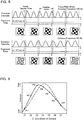
- Fig. 5 shows a relationship between the lighting frequency of the interior lamp and the frame rate of the camera 141 when imaging is performed at the frame rate of 60 fps.
- the upper row shows the case of the power source frequency being 60 Hz
- the lower row shows the case of the power source frequency being 50 Hz.
- the camera 141 receives light during 1/60 s (approximately 16.7 msec) from when it starts exposure, and transfers an image to the PC 2 when the light reception ends.
- the camera 141 starts exposure again when it finishes the image transfer to the PC2, and subsequently repeats the same operation.
- a relatively long time is set for the image transfer time.
- the power source frequency is 60 Hz
- the exposure time of the camera 141 is not an integral multiple of the lighting period of the interior lamp. Hence, the amount of light to be received by the camera 141 is different from one imaging shot to another, and a flicker is generated in the acquired images.
- the contrast-type auto-focusing calculates a contrast from an image acquired by the camera 141.
- a flicker is generated in an image acquired by the camera 141, it is difficult to calculate the contrast correctly.
- Fig. 6 is a diagram in which the contrasts which are supposed to be obtained if no flicker occurs are compared with the contrasts with errors due to the flicker, wherein the vertical axis represents the contrast, and the horizontal axis represents the Z-coordinate of the camera.
- the curve indicated by a dashed line represents the contrasts supposed to be obtained, and the curve indicated by a solid line represents the contrasts with errors.
- the contrast peak shifts to a position that is different from the supposed-to-be position.
- the contrast P3' becomes higher than the contrast P4', and the coordinate Z3 is judged as the in-focus position instead of the coordinate Z4 that is supposed to be the in-focus position.
- Fig. 7 shows a diagram that is basically the same as Fig. 5 .
- the frame rate is set to 50 fps in Fig. 7 whereas it is set to 60 fps in Fig. 5 .
- no flicker occurs among the images acquired by the camera 141 when the lighting frequency of the interior lamp is 100 Hz, whereas a flicker occurs when the lighting frequency of the interior lamp is 120 Hz.
- Fig. 8 also shows a diagram that is basically the same as Fig. 5 and Fig. 7 , but the frame rate of the camera is set to 20 fps in Fig. 8 .
- the exposure time of 50 ms is an integral multiple of the lighting period of the interior lamp. Therefore, no flicker will occur.
- the imaging speed will greatly drop and auto-focusing will take an enormous time.
- the present invention employs adjusting the exposure time of the camera 141 according to the lighting frequency of the interior lamp.
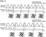
- This adjusting method is shown in Fig. 9.
- Fig. 9 is basically the same as Fig. 5 , but different in that the exposure time of the camera is set to 1/60 s when the power source frequency is 60 Hz while it is set to 1/50 s when the power source frequency is 50 Hz.
- the exposure time of the camera is twice as long as the time of one period of the lighting frequency of the interior lamp, it needs not be twice as long but needs only to be an integral multiple.
- the exposure time of the camera 141 needs only to be set to an integral multiple of the lighting period of the interior lamp, and is irrelevant to the frame rate.
- the exposure time set in this way ensures that a constant amount of light is always received during exposure even if the timing at which exposure starts within a frame period is inconstant, and hence prevents a flicker.
- Fig. 10 shows the flow of a process for detecting the lighting period of the interior lamp.
- Fig. 10 is a flowchart of a frame rate adjusting method for setting the frame rate of the camera to 120 fps when the power source frequency described above is 60 Hz and to 100 fps when the power source frequency is 50 Hz, which is implemented by software.
- the PC 2 first turns off the illumination device 142 to see the influence of external diffused light (S1).
- the frame rate of the camera 141 is set to 100 fps (S2).
- imaging by the camera 141 is performed to acquire images of the workpiece 3, and the fluctuation rate of the average brightness is calculated (S3).
- the frame rate of the camera 141 is changed to 120 fps (S4). Images of the workpiece 3 are acquired and the fluctuation rate of the average brightness is calculated (S5). Finally, the fluctuation rate of the average brightness when the frame rate of the camera 141 is set to 100 fps is compared with the fluctuation rate of the average brightness when the frame rate of the camera 141 is set to 120 fps, and the frame rate of the camera 141 is set to the frame rate corresponding to the lower one of the fluctuation rates of the average brightness (S6).
- the frame rate of the camera 141 may be first set to 60 fps and then changed to 50 fps.
- step S6 when both of the fluctuation rates of the average brightness compared are equal to or higher than a certain threshold, the frame rate may be set to 60 fps. When both of the calculated fluctuation rates of the average brightness are low, the frame rate may be set manually. Such a method as described above may be executed when the vision measuring device or the dedicated software is started.
- the operation of the illumination device 142 of the vision measuring device according to the present embodiment will be explained.
- a PWM-controlled LED is used as the illumination device 142, and the PWM frequency is set to an integral multiple of 600 Hz which is the least common multiple of 120 and 100. The reason of this will be explained below.
- Fig. 11 is a timing chart showing the relationship between the emission time of the illumination device 142 and the exposure time of the camera 141 when the PWM frequency is set to 480 Hz.
- the upper row shows the case when the frame rate of the camera 141 is 60 fps, and the lower row shows the case when the frame rate of the camera 141 is 50 fps.
- the PWM frequency is 480 Hz and the frame rate of the camera 141 is 60 fps as shown in the upper row of Fig. 11 , the PWM frequency is eight times as large as the frame rate.
- the camera 141 receives an amount of light corresponding to eight pulses from the illumination device 142, and the acquired images all have the same amount of light.
- the PWM frequency of the camera is 9.6 times as large as the frame rate of the camera.
- the PWM frequency of the illumination device 142 is not an integral multiple of the frame rate. As a result, like the example of the lower row of Fig.
- the vision measuring device sets the emission frequency of the illumination device 142 to a multiple of 600 Hz.
- Fig. 12 shows what it is like when the emission frequency of the illumination device 142 is set to a multiple of 600 Hz.
- Fig. 12 is basically the same as Fig. 11 but different in that the emission frequency of the illumination device 142 is set to 600 Hz.
- the amount of light by which the workpiece 3 is irradiated by the illumination device 142 during one exposure time of the camera 141 is an amount corresponding to ten pulses of the illumination device 142.
- the emission frequency of the illumination device 142 is set to 600 Hz. However, it is only necessary that the emission frequency be a common multiple of the plurality of frame rates to select from. For example, when selecting the frame rate of the camera from between 50 fps and 60 fps, it is possible to set the emission frequency to 300 Hz which is the least common multiple of these frame rates. When setting the frame rate of the camera 141 to any other values than 50 fps and 60 fps, it is possible to adjust the emission frequency of the illumination device 142 automatically to an integral multiple of the frame rates of the camera 141. Moreover, it is also possible to make the illumination device 142 receive a vertical synchronization signal from the camera 141 and emit light by only a fixed number of pulses within the exposure time.
- the vision measuring device is the same as the first embodiment except the following point.
- what is sent from the PC 2 to the illumination control device 152 is not a PWM frequency instruction but a brightness instruction.
- the illumination device 142 may be a PWM-controlled LED or any other illuminator.
- the contrast-type auto-focusing employed by the vision measuring device according to the present comparative example can figure out the correct in-focus position by increasing image output positions. However, if the image output positions are increased, the amount of data to be sent from the camera 141 to the PC 2 is increased. In the present example, because the camera 141 and the PC 2 are connected through a USB interface, the image data transfer speed is limited to approximately 400 Mbps, which increases the time taken for auto-focusing. Hence, the vision measuring device according to the present example reduces the amount of data to be sent from the camera 141 to the PC 2 by sending only a partial image that is cut out from the image of the imaging range during auto-focusing, thereby raising the frame rate.
- Fig. 14 is a timing chart showing the signals exchanged between the camera 141 and the PC 2 during auto-focusing of the vision measuring device according to the present example.
- the upper row shows some of the signals to be sent from the PC 2 to the camera 141, and the lower row shows the signals to be sent from the camera 141 to the PC 2.
- the image data representing the whole imaging range is sent from the camera 141 to the PC 2 as shown in the lower left of Fig. 14 , for example.
- an instruction to the effect that image output should be stopped is sent from the PC 2 to the camera 141 at the timing S1
- image output by the camera 141 is stopped
- an instruction to the effect that the latch counter should be reset is sent from the camera 141 to the position control system 151.
- the latch counter is reset, the camera 141 is driven to the auto-focusing start position.
- an instruction designating an image output range is sent from the PC 2 to the camera 141.
- the range of the image to be sent from the camera 141 to the PC 2 is restricted as shown in the picture in the lower center of Fig. 14 , for example.
- an instruction to the effect that a vertical synchronization signal should be output may also be issued simultaneously.
- an instruction to the effect that image output should be started is sent from the PC 2 to the camera 141, and hence image data and a time stamp are output from the camera 141 to the PC 2.
- a vertical synchronization signal is sent from the camera 141 to the position control system 151, and hence the Z-coordinate of the camera 141 when it acquired the image and the time stamp are retained in the position control system 151.
- a different way may be used to synchronize the camera 141 and the position control system 151 such as calculating the imaging timing of the camera 141 from the frame rate of the camera 141 and obtaining the Z-coordinate of the camera 141 at the calculated timing.
- an instruction to the effect that image output should be stopped is sent from the PC 2 to the camera 141.
- a signal to the effect that the settings of the camera 141 during the auto-focusing (the designation of the image output range and output of a vertical synchronization signal) should be canceled is sent.
- a Z-move stop instruction, a latch stop instruction, and a latch number readout instruction are sent from the PC 2 to the position control system 151.
- the position control system 151 stops the camera 141 from moving, stops the operation of the latch counter and Z-value latch buffer, and sends the latch number to the PC 2.
- a latch data readout instruction is output from the PC 2 to the position control system 151, and the data (Z-coordinate and time stamp) in the Z-value latch buffer is sent from the position control system 151 to the PC 2.
- the PC 2 associates the image data with the Z-coordinate based on their time stamps, and figures out the relationship between the contrast calculated from the image data and the Z-value. After this, judging that a Z-value at which the image with the highest contrast was acquired as the in-focus position, the PC 2 causes the camera 141 to be moved such that its Z-coordinate becomes the calculated in-focus position.
- the size of the image to be sent from the camera 141 to the PC 2 is reduced, and the frame rate of the camera 141 can be increased significantly regardless of the transfer rate of the USB interface.
- this method has to reduce the exposure time per frame, which results in reduction of the amount of light in the acquired image. Hence, the contrast and the auto-focusing accuracy become lower.
- Fig. 15 is a block diagram for explaining the illumination control method of the vision measuring device according to the present example.
- the illumination control device 152 and the camera 141 are connected in parallel to the PC 2, and the illumination device 142 is connected to the illumination control device 152.
- an instruction to the effect that image output should be stopped is output at the timing S1 of Fig. 14 the same as described above, and an instruction to the effect that image output should be started is output at the timing S3.
- a brightness instruction is sent from the PC 2 to the illumination control device 152 within the period from the timing S1 till the timing S3, i.e., within the period from when image output from the camera 141 to the PC 2 is stopped till when image output is resumed at the designated frame rate.
- the vision measuring device according to the present example is the same as the vision measuring device according to the previous example except the following point.
- the vision measuring device according to the present example controls the light volume of the illumination device 142 based on a vertical synchronization signal output from the camera 141.
- Fig. 16 is a block diagram for explaining an illumination control method of the vision measuring device according to the present example.
- the vision measuring device according to the present example is basically the same as the vision measuring device according to the previous example.
- the vision measuring device according to the present example is different in that the controller 15 further includes a frame rate detecting device 153 and a standard frame rate retaining unit 154, which are connected to the camera 141 and the illumination control device 152.
- a vertical synchronization signal is output from the camera 141 to the frame rate detecting device 153.
- the frame rate detecting device 153 calculates the frame rate of the camera 141 from the vertical synchronization signal and outputs the calculated frame rate to the illumination control device 152.
- the difference between the calculated frame rate and a standard frame rate output by the standard frame rate retaining unit 154 is input to the illumination control device 152.
- an illuminance defined by the color, reflectivity, etc. of the surface of the workpiece that are output by the PC 2 may be input as a standard value to the illumination control device 152 and may further be adjusted based on the frame rate.
- Fig. 17 is a timing chart showing the light volume of the illumination device 142, the gain of the camera 141, and signals to be output by the camera 141 in the vision measuring device according to the present comparative example.
- the light volume of the illumination device 142 is shown in the upper row
- the gain of the camera 141 is shown in the middle row
- the signals to be output by the camera 141 are shown in the lower row.
- the light volume of the illumination device 142 is a constant value.
- the illumination control device 142 increases the light volume of the illumination device 142 in response to a vertical synchronization signal output by the camera 141.
- the illumination control device 142 When auto-focusing is completed at the timing S12, the illumination control device 142 returns the light volume of the illumination device 142 to the light volume in the normal measurement in response to that the camera 141 stops outputting the vertical synchronization signal.
- the vertical synchronization signal is output by the camera 141 only during auto-focusing, it may be output constantly.
- the frame rate of the camera 141 and the light volume of the illumination device 142 are controlled separately by the PC 2. Therefore, there is a risk that any delay in the calculation process of the PC 2, etc. might lag the timing to give an instruction to the camera 141 and the timing to give an instruction to the illumination device 142 one behind another. Therefore, there is a possibility that a phenomenon that is not desirable for the measurement operation might occur, such as instantaneous darkening or conversely instantaneous excessive brightening of the image that is displayed on the PC 2 when the normal measurement and auto-focusing are switched.
- the frame rate of the camera 141 and the light volume of the illumination device 142 are directly synchronized by the vertical synchronization signal. Therefore, it is possible to perform imaging at an appropriate light volume at all times even when normal measurement and auto-focusing are switched, and to prevent any troubles such as fluctuation of the brightness in the screen of the PC 2, etc.
- the vision measuring device according to the present example is substantially the same as the vision measuring device according to the previous example, but different in adjusting the gain of the camera 141 under a certain condition described later.
- Fig. 18 is a timing chart showing the light volume of the illumination device 142, the gain of the camera 141, and the signals to be output by the camera 141 in the auto-focusing of the vision measuring device according to the present example.
- Fig. 18 is basically the same as Fig. 17 , but different in that during auto-focusing, the light volume of the illumination device 142 is increased to the maximum output and the gain of the camera 141 is increased.
- the vision measuring device increases the light volume of the illumination device 142 during auto-focusing.
- a light volume higher than the maximum output of the illumination device 142 might be required.
- the present example compensates for any shortage in the light volume of the illumination device 142 by increasing the gain of the camera 141.
- Such a configuration can realize highly accurate and high-speed auto-focusing with excellent operability even when the light volume of the illumination device 142 is insufficient.
Landscapes
- Engineering & Computer Science (AREA)
- Multimedia (AREA)
- Signal Processing (AREA)
- Physics & Mathematics (AREA)
- General Physics & Mathematics (AREA)
- Optics & Photonics (AREA)
- Studio Devices (AREA)
- Automatic Focus Adjustment (AREA)
- Eye Examination Apparatus (AREA)
- Focusing (AREA)
Claims (6)
- Sichtmessvorrichtung, umfassend eine Bilderfassungsvorrichtung (141) mit variabler Belichtungszeit, wobei die Sichtmessvorrichtung angepasst ist zum Messen eines Werkstücks (3) durch Abbilden des Werkstücks (3) mithilfe der Bilderfassungsvorrichtung (141), und ferner Folgendes umfassend:eine Beleuchtungsvorrichtung (142), angeordnet, gesteuert zu werden, um Licht mit einer bestimmten Ausgabefrequenz auszugeben und das Werkstück (3) mit Beleuchtungslicht zu bestrahlen;einen Lineargeber (143), angeordnet, eine fokussierte Position der Bilderfassungsvorrichtung (141) in einer Fokussierungsachsenrichtung zu steuern und auszugeben;ein Positionssteuersystem (151), angeordnet, die fokussierte Position der Bilderfassungsvorrichtung (141) zu steuern, und angeordnet, die fokussierte Position der Bilderfassungsvorrichtung (141) von dem Lineargeber (143) zu erfassen, und ferner angeordnet, die fokussierte Position als Informationen auszugeben, die eine Position in einer Fokussierungsachsenrichtung darstellen; unddie Sichtmessvorrichtung eine Steuervorrichtung (2) umfasst und angeordnet ist, Folgendes auszuführen:eine normale Messung, bei der die Bilderfassungsvorrichtung (141) das Werkstück (3) mit einer Bildfrequenz abbildet und die Beleuchtungsvorrichtung das Werkstück (3) bestrahlt; undeinen Autofokussierungsvorgang, umfassend das Erfassen der fokussierten Position, in der ein Bild mit dem höchstmöglichen Kontrast erzielt wird, wobei die Steuervorrichtung (2) angeordnet ist, während des Autofokussierens die Belichtungszeit der Bilderfassungsvorrichtung (141) auf ein ganzzahliges Vielfaches einer Beleuchtungsperiode einer Innenlampe einzustellen, auf dessen Grundlage eine erste Frequenz, zum Beispiel 100 Hz, und eine zweite Frequenz, zum Beispiel 120 Hz, eine Beleuchtungsfrequenz der Innenlampe ist, wobeidie Ausgabefrequenz der Beleuchtungsvorrichtung (142) auf ein gemeinsames Vielfaches der ersten Frequenz und der zweiten Frequenz eingestellt ist, zum Beispiel auf ein ganzzahliges Vielfaches von 600 Hz.
- Sichtmessvorrichtung nach Anspruch 1, wobei
die Steuervorrichtung (2) angeordnet ist, die Beleuchtungsfrequenz der Innenlampe zu erkennen, wenn die Beleuchtungsvorrichtung (142) ausgeschaltet ist. - Vorrichtung nach Anspruch 1 oder 2, wobei
die Steuervorrichtung (2) angeordnet ist, das Positionssteuersystem (151) sowohl in einem Fall, in dem die Belichtungszeit der Bilderfassungsvorrichtung (141) auf ein ganzzahliges Vielfaches einer Beleuchtungsperiode eingestellt ist, welches der ersten Frequenz entspricht, als auch in einem Fall, in dem die Belichtungszeit der Bilderfassungsvorrichtung (141) auf ein ganzzahliges Vielfaches einer Beleuchtungsperiode eingestellt ist, welches der zweiten Frequenz entspricht, sodass die Bilderfassungsvorrichtung eine Bilderfassung in verschiedenen fokussierten Positionen durchführt, welche diesen Fällen entsprechen,
die Steuervorrichtung (2) angeordnet ist, eine Schwankungsrate durchschnittlicher Helligkeit erfasster Bilder zu berechnen, und
die Steuervorrichtung (2) angeordnet ist, die Belichtungszeit der Bilderfassungsvorrichtung (141) auf ein ganzzahliges Vielfaches der Beleuchtungsperiode einzustellen, entsprechend entweder der ersten Frequenz oder der zweiten Frequenz, die einer geringeren Schwankungsrate durchschnittlicher Helligkeit entspricht. - Sichtmessvorrichtung nach einem der vorhergehenden Ansprüche, wobei
die Steuervorrichtung (2) angeordnet ist, die fokussierte Position der Bilderfassungsvorrichtung (141) einzustellen, nachdem drei oder mehr Bilder des Werkstücks (3) erfasst sind. - Sichtmessvorrichtung nach einem der vorhergehenden Ansprüche, wobei
die Beleuchtungsvorrichtung (142) angeordnet ist, ein vertikales Synchronisierungssignal von der Bilderfassungsvorrichtung (141) zu empfangen und eine bestimmte Anzahl von Impulsen innerhalb der Belichtungszeit der Bilderfassungsvorrichtung (141) auszugeben. - Sichtmessvorrichtung nach einem der vorhergehenden Ansprüche, wobei
die Steuervorrichtung (2) angeordnet ist, eine lange Belichtungszeit einzustellen, wenn das Werkstück (3) mit externem diffusem Licht bestrahlt wird, das von der Innenlampe verschieden ist.
Applications Claiming Priority (3)
| Application Number | Priority Date | Filing Date | Title |
|---|---|---|---|
| JP2011009513A JP5740647B2 (ja) | 2011-01-20 | 2011-01-20 | 画像測定装置 |
| JP2011014899A JP5584873B2 (ja) | 2011-01-27 | 2011-01-27 | 画像測定装置 |
| EP12151395.6A EP2479536B1 (de) | 2011-01-20 | 2012-01-17 | Optische Messvorrichtung mit Autofokus |
Related Parent Applications (3)
| Application Number | Title | Priority Date | Filing Date |
|---|---|---|---|
| EP12151395.6 Division | 2012-01-17 | ||
| EP12151395.6A Division-Into EP2479536B1 (de) | 2011-01-20 | 2012-01-17 | Optische Messvorrichtung mit Autofokus |
| EP12151395.6A Division EP2479536B1 (de) | 2011-01-20 | 2012-01-17 | Optische Messvorrichtung mit Autofokus |
Publications (2)
| Publication Number | Publication Date |
|---|---|
| EP2607839A1 EP2607839A1 (de) | 2013-06-26 |
| EP2607839B1 true EP2607839B1 (de) | 2017-08-02 |
Family
ID=45524333
Family Applications (3)
| Application Number | Title | Priority Date | Filing Date |
|---|---|---|---|
| EP13160577.6A Active EP2607840B1 (de) | 2011-01-20 | 2012-01-17 | Optische Messvorrichtung mit Autofokus |
| EP13160574.3A Active EP2607839B1 (de) | 2011-01-20 | 2012-01-17 | Optische Messvorrichtung mit Autofokus |
| EP12151395.6A Active EP2479536B1 (de) | 2011-01-20 | 2012-01-17 | Optische Messvorrichtung mit Autofokus |
Family Applications Before (1)
| Application Number | Title | Priority Date | Filing Date |
|---|---|---|---|
| EP13160577.6A Active EP2607840B1 (de) | 2011-01-20 | 2012-01-17 | Optische Messvorrichtung mit Autofokus |
Family Applications After (1)
| Application Number | Title | Priority Date | Filing Date |
|---|---|---|---|
| EP12151395.6A Active EP2479536B1 (de) | 2011-01-20 | 2012-01-17 | Optische Messvorrichtung mit Autofokus |
Country Status (3)
| Country | Link |
|---|---|
| US (1) | US8866114B2 (de) |
| EP (3) | EP2607840B1 (de) |
| CN (1) | CN102607638B (de) |
Families Citing this family (20)
| Publication number | Priority date | Publication date | Assignee | Title |
|---|---|---|---|---|
| US8766153B2 (en) * | 2011-02-17 | 2014-07-01 | Mitutoyo Corporation | Vision measuring device and auto-focusing control method |
| DE102012109726A1 (de) * | 2012-09-04 | 2014-04-03 | Werth Messtechnik Gmbh | Verfahren und Vorrichtung zur Bestimmung der Geometrie eines Objektes mit einer Zoomoptik |
| US20140078278A1 (en) * | 2012-09-19 | 2014-03-20 | Omnivision Technologies, Inc. | Systems and Methods for Controlling Lighting Strength of a Camera System by Time-Matched Intermittent Illumination |
| ES2978794T3 (es) * | 2013-01-04 | 2024-09-20 | Meso Scale Technologies Llc | Aparatos, métodos y reactivos de ensayo |
| JP6244104B2 (ja) | 2013-05-08 | 2017-12-06 | 株式会社ミツトヨ | 画像測定装置の照明設定方法、装置及びブライトネスツール用コンピュータソフトウェア |
| JP6108946B2 (ja) * | 2013-05-10 | 2017-04-05 | キヤノン株式会社 | 撮像装置、制御方法、プログラム及び記憶媒体 |
| DE102013106696B4 (de) | 2013-06-26 | 2019-10-10 | Gom Gmbh | Steuerungseinheit für eine optische Vermessungseinrichtung und Verfahren zur Steuerung einer optischen Vermessungseinrichtung |
| US9912884B2 (en) | 2014-03-03 | 2018-03-06 | Photoneo, s.r.o. | Methods and apparatus for superpixel modulation |
| CN106017325B (zh) * | 2014-07-16 | 2018-11-02 | 佛山科学技术学院 | 一种改进的复杂表面和不规则物体体积的非接触光学测量方法 |
| CN104601987B (zh) * | 2015-02-03 | 2015-10-28 | 厦门狄耐克电子科技有限公司 | 楼宇可视对讲系统视频帧率的测量方法及装置 |
| JP6566737B2 (ja) | 2015-06-18 | 2019-08-28 | キヤノン株式会社 | 情報処理装置、情報処理方法、プログラム |
| CN107923737B (zh) * | 2015-12-13 | 2019-12-17 | 富通尼奥有限责任公司 | 用于超像素调制和环境光抑制的方法和设备 |
| TWI607412B (zh) | 2016-09-10 | 2017-12-01 | 財團法人工業技術研究院 | 多維度尺寸量測系統及其方法 |
| US10992876B2 (en) * | 2016-10-18 | 2021-04-27 | Texas Instruments Incorporated | WDR imaging with LED flicker mitigation |
| CN109041383A (zh) * | 2018-08-31 | 2018-12-18 | 华勤通讯技术有限公司 | 移动终端中闪光灯的控制方法和系统 |
| CN109341579B (zh) * | 2018-10-26 | 2020-10-27 | 巨轮(广州)机器人与智能制造有限公司 | 车灯外形检测方法 |
| CN115325960B (zh) * | 2021-05-10 | 2025-02-18 | 广州视源电子科技股份有限公司 | 多频相移测量方法、装置、存储介质及设备 |
| US12488450B2 (en) * | 2021-07-27 | 2025-12-02 | Konica Minolta, Inc. | Image capture condition adjustment device, image capture condition adjustment method, and program |
| CN113899312B (zh) * | 2021-09-30 | 2022-06-21 | 苏州天准科技股份有限公司 | 一种影像测量设备及影像测量方法 |
| US12159439B2 (en) * | 2021-12-02 | 2024-12-03 | Lumileds Llc | LED array optimization using artificial neural networks |
Citations (2)
| Publication number | Priority date | Publication date | Assignee | Title |
|---|---|---|---|---|
| US6268918B1 (en) * | 1998-06-18 | 2001-07-31 | Minolta Co., Ltd. | Three-dimensional input device |
| EP1533996A1 (de) * | 2003-11-24 | 2005-05-25 | Mitutoyo Corporation | System und Verfahren zur schnellen automatischen Fokussierung eines Maschinenvisionssystems |
Family Cites Families (12)
| Publication number | Priority date | Publication date | Assignee | Title |
|---|---|---|---|---|
| US5880777A (en) * | 1996-04-15 | 1999-03-09 | Massachusetts Institute Of Technology | Low-light-level imaging and image processing |
| JP4113387B2 (ja) * | 2002-07-24 | 2008-07-09 | シャープ株式会社 | 携帯端末装置並びに情報読取プログラム及びそのプログラムを記録した記録媒体 |
| JP2005003385A (ja) * | 2003-06-09 | 2005-01-06 | Mitsutoyo Corp | 画像測定方法、および画像測定装置 |
| US20070177860A1 (en) | 2004-03-15 | 2007-08-02 | Anthony Hooley | Camera autofocus |
| JP2007006343A (ja) | 2005-06-27 | 2007-01-11 | Olympus Corp | 撮像システム |
| US7855743B2 (en) * | 2006-09-08 | 2010-12-21 | Sony Corporation | Image capturing and displaying apparatus and image capturing and displaying method |
| JP2008197144A (ja) | 2007-02-08 | 2008-08-28 | Fujifilm Corp | 撮影装置、撮影レンズの合焦制御方法及び制御装置 |
| JP2008224808A (ja) | 2007-03-09 | 2008-09-25 | Canon Inc | 自動合焦装置および撮像装置 |
| JP5202966B2 (ja) | 2008-01-16 | 2013-06-05 | 株式会社ミツトヨ | 画像測定方法および画像測定装置 |
| US8149323B2 (en) * | 2008-12-18 | 2012-04-03 | Qualcomm Incorporated | System and method to autofocus assisted by autoexposure control |
| JP2010160284A (ja) | 2009-01-07 | 2010-07-22 | Hoya Corp | 撮像装置 |
| JP5183565B2 (ja) | 2009-05-11 | 2013-04-17 | キヤノン株式会社 | 撮像装置 |
-
2012
- 2012-01-13 US US13/350,286 patent/US8866114B2/en active Active
- 2012-01-17 EP EP13160577.6A patent/EP2607840B1/de active Active
- 2012-01-17 EP EP13160574.3A patent/EP2607839B1/de active Active
- 2012-01-17 EP EP12151395.6A patent/EP2479536B1/de active Active
- 2012-01-20 CN CN201210020710.1A patent/CN102607638B/zh active Active
Patent Citations (2)
| Publication number | Priority date | Publication date | Assignee | Title |
|---|---|---|---|---|
| US6268918B1 (en) * | 1998-06-18 | 2001-07-31 | Minolta Co., Ltd. | Three-dimensional input device |
| EP1533996A1 (de) * | 2003-11-24 | 2005-05-25 | Mitutoyo Corporation | System und Verfahren zur schnellen automatischen Fokussierung eines Maschinenvisionssystems |
Also Published As
| Publication number | Publication date |
|---|---|
| EP2607839A1 (de) | 2013-06-26 |
| US8866114B2 (en) | 2014-10-21 |
| US20120187275A1 (en) | 2012-07-26 |
| CN102607638A (zh) | 2012-07-25 |
| EP2479536B1 (de) | 2017-08-09 |
| EP2479536A2 (de) | 2012-07-25 |
| EP2607840A1 (de) | 2013-06-26 |
| EP2607840B1 (de) | 2017-08-16 |
| CN102607638B (zh) | 2016-03-16 |
| EP2479536A3 (de) | 2012-09-12 |
Similar Documents
| Publication | Publication Date | Title |
|---|---|---|
| EP2479536B1 (de) | Optische Messvorrichtung mit Autofokus | |
| CN103051843B (zh) | 摄像装置以及摄像装置的闪烁检测方法 | |
| RU2627933C2 (ru) | Устройство захвата изображения и способ управления им | |
| US8218069B2 (en) | Camera body with which various flash devices can be interchangeably used | |
| CN110798671B (zh) | 投影装置亮度的自适应调节方法及调节系统 | |
| JP2010114834A (ja) | 撮像装置 | |
| US10972677B2 (en) | Imaging control apparatus and imaging control method | |
| US9182356B2 (en) | Image processing apparatus | |
| JP2018119942A (ja) | 撮像装置及びその監視方法並びにプログラム | |
| JP2010103746A (ja) | 撮像装置 | |
| US9232152B2 (en) | Image capturing apparatus and control method thereof for correcting exposure unevenness caused by an external light change | |
| US20060232701A1 (en) | Autofocus device and method | |
| JP6244104B2 (ja) | 画像測定装置の照明設定方法、装置及びブライトネスツール用コンピュータソフトウェア | |
| JP2019161499A (ja) | 撮像装置 | |
| US11080863B2 (en) | Imaging apparatus, image processing device, and control method | |
| JP2016154285A (ja) | 撮像装置、電子機器及び光量変化特性の算出方法 | |
| CN105867047A (zh) | 闪光灯的调整方法及拍摄装置 | |
| US20210400252A1 (en) | Imaging method, imaging system, manufacturing system, and method for manufacturing a product | |
| CN102645160B (zh) | 图像测量设备 | |
| US8994793B2 (en) | Image capture device, controller and computer program | |
| US20070002286A1 (en) | Light source driving method and projector | |
| US6013911A (en) | Lamp illumination control system and method | |
| JP5740647B2 (ja) | 画像測定装置 | |
| JP5584873B2 (ja) | 画像測定装置 | |
| JP2009042098A (ja) | 画像処理式物体検出装置 |
Legal Events
| Date | Code | Title | Description |
|---|---|---|---|
| AC | Divisional application: reference to earlier application |
Ref document number: 2479536 Country of ref document: EP Kind code of ref document: P |
|
| AK | Designated contracting states |
Kind code of ref document: A1 Designated state(s): AL AT BE BG CH CY CZ DE DK EE ES FI FR GB GR HR HU IE IS IT LI LT LU LV MC MK MT NL NO PL PT RO RS SE SI SK SM TR |
|
| AX | Request for extension of the european patent |
Extension state: BA ME |
|
| PUAI | Public reference made under article 153(3) epc to a published international application that has entered the european phase |
Free format text: ORIGINAL CODE: 0009012 |
|
| 17P | Request for examination filed |
Effective date: 20131224 |
|
| RBV | Designated contracting states (corrected) |
Designated state(s): AL AT BE BG CH CY CZ DE DK EE ES FI FR GB GR HR HU IE IS IT LI LT LU LV MC MK MT NL NO PL PT RO RS SE SI SK SM TR |
|
| 17Q | First examination report despatched |
Effective date: 20160921 |
|
| GRAP | Despatch of communication of intention to grant a patent |
Free format text: ORIGINAL CODE: EPIDOSNIGR1 |
|
| INTG | Intention to grant announced |
Effective date: 20170309 |
|
| RIN1 | Information on inventor provided before grant (corrected) |
Inventor name: YOSHIDA, HIROYUKI Inventor name: SHIRAI, NAOKI |
|
| GRAS | Grant fee paid |
Free format text: ORIGINAL CODE: EPIDOSNIGR3 |
|
| GRAA | (expected) grant |
Free format text: ORIGINAL CODE: 0009210 |
|
| AC | Divisional application: reference to earlier application |
Ref document number: 2479536 Country of ref document: EP Kind code of ref document: P |
|
| AK | Designated contracting states |
Kind code of ref document: B1 Designated state(s): AL AT BE BG CH CY CZ DE DK EE ES FI FR GB GR HR HU IE IS IT LI LT LU LV MC MK MT NL NO PL PT RO RS SE SI SK SM TR |
|
| REG | Reference to a national code |
Ref country code: GB Ref legal event code: FG4D |
|
| REG | Reference to a national code |
Ref country code: CH Ref legal event code: EP Ref country code: AT Ref legal event code: REF Ref document number: 914958 Country of ref document: AT Kind code of ref document: T Effective date: 20170815 |
|
| REG | Reference to a national code |
Ref country code: IE Ref legal event code: FG4D |
|
| REG | Reference to a national code |
Ref country code: DE Ref legal event code: R096 Ref document number: 602012035518 Country of ref document: DE |
|
| REG | Reference to a national code |
Ref country code: NL Ref legal event code: MP Effective date: 20170802 |
|
| REG | Reference to a national code |
Ref country code: AT Ref legal event code: MK05 Ref document number: 914958 Country of ref document: AT Kind code of ref document: T Effective date: 20170802 |
|
| REG | Reference to a national code |
Ref country code: LT Ref legal event code: MG4D |
|
| REG | Reference to a national code |
Ref country code: FR Ref legal event code: PLFP Year of fee payment: 7 |
|
| PG25 | Lapsed in a contracting state [announced via postgrant information from national office to epo] |
Ref country code: FI Free format text: LAPSE BECAUSE OF FAILURE TO SUBMIT A TRANSLATION OF THE DESCRIPTION OR TO PAY THE FEE WITHIN THE PRESCRIBED TIME-LIMIT Effective date: 20170802 Ref country code: NL Free format text: LAPSE BECAUSE OF FAILURE TO SUBMIT A TRANSLATION OF THE DESCRIPTION OR TO PAY THE FEE WITHIN THE PRESCRIBED TIME-LIMIT Effective date: 20170802 Ref country code: AT Free format text: LAPSE BECAUSE OF FAILURE TO SUBMIT A TRANSLATION OF THE DESCRIPTION OR TO PAY THE FEE WITHIN THE PRESCRIBED TIME-LIMIT Effective date: 20170802 Ref country code: HR Free format text: LAPSE BECAUSE OF FAILURE TO SUBMIT A TRANSLATION OF THE DESCRIPTION OR TO PAY THE FEE WITHIN THE PRESCRIBED TIME-LIMIT Effective date: 20170802 Ref country code: NO Free format text: LAPSE BECAUSE OF FAILURE TO SUBMIT A TRANSLATION OF THE DESCRIPTION OR TO PAY THE FEE WITHIN THE PRESCRIBED TIME-LIMIT Effective date: 20171102 Ref country code: SE Free format text: LAPSE BECAUSE OF FAILURE TO SUBMIT A TRANSLATION OF THE DESCRIPTION OR TO PAY THE FEE WITHIN THE PRESCRIBED TIME-LIMIT Effective date: 20170802 Ref country code: LT Free format text: LAPSE BECAUSE OF FAILURE TO SUBMIT A TRANSLATION OF THE DESCRIPTION OR TO PAY THE FEE WITHIN THE PRESCRIBED TIME-LIMIT Effective date: 20170802 |
|
| PG25 | Lapsed in a contracting state [announced via postgrant information from national office to epo] |
Ref country code: LV Free format text: LAPSE BECAUSE OF FAILURE TO SUBMIT A TRANSLATION OF THE DESCRIPTION OR TO PAY THE FEE WITHIN THE PRESCRIBED TIME-LIMIT Effective date: 20170802 Ref country code: ES Free format text: LAPSE BECAUSE OF FAILURE TO SUBMIT A TRANSLATION OF THE DESCRIPTION OR TO PAY THE FEE WITHIN THE PRESCRIBED TIME-LIMIT Effective date: 20170802 Ref country code: BG Free format text: LAPSE BECAUSE OF FAILURE TO SUBMIT A TRANSLATION OF THE DESCRIPTION OR TO PAY THE FEE WITHIN THE PRESCRIBED TIME-LIMIT Effective date: 20171102 Ref country code: PL Free format text: LAPSE BECAUSE OF FAILURE TO SUBMIT A TRANSLATION OF THE DESCRIPTION OR TO PAY THE FEE WITHIN THE PRESCRIBED TIME-LIMIT Effective date: 20170802 Ref country code: GR Free format text: LAPSE BECAUSE OF FAILURE TO SUBMIT A TRANSLATION OF THE DESCRIPTION OR TO PAY THE FEE WITHIN THE PRESCRIBED TIME-LIMIT Effective date: 20171103 Ref country code: RS Free format text: LAPSE BECAUSE OF FAILURE TO SUBMIT A TRANSLATION OF THE DESCRIPTION OR TO PAY THE FEE WITHIN THE PRESCRIBED TIME-LIMIT Effective date: 20170802 Ref country code: IS Free format text: LAPSE BECAUSE OF FAILURE TO SUBMIT A TRANSLATION OF THE DESCRIPTION OR TO PAY THE FEE WITHIN THE PRESCRIBED TIME-LIMIT Effective date: 20171202 |
|
| PG25 | Lapsed in a contracting state [announced via postgrant information from national office to epo] |
Ref country code: DK Free format text: LAPSE BECAUSE OF FAILURE TO SUBMIT A TRANSLATION OF THE DESCRIPTION OR TO PAY THE FEE WITHIN THE PRESCRIBED TIME-LIMIT Effective date: 20170802 Ref country code: RO Free format text: LAPSE BECAUSE OF FAILURE TO SUBMIT A TRANSLATION OF THE DESCRIPTION OR TO PAY THE FEE WITHIN THE PRESCRIBED TIME-LIMIT Effective date: 20170802 Ref country code: CZ Free format text: LAPSE BECAUSE OF FAILURE TO SUBMIT A TRANSLATION OF THE DESCRIPTION OR TO PAY THE FEE WITHIN THE PRESCRIBED TIME-LIMIT Effective date: 20170802 |
|
| REG | Reference to a national code |
Ref country code: DE Ref legal event code: R097 Ref document number: 602012035518 Country of ref document: DE |
|
| PG25 | Lapsed in a contracting state [announced via postgrant information from national office to epo] |
Ref country code: SK Free format text: LAPSE BECAUSE OF FAILURE TO SUBMIT A TRANSLATION OF THE DESCRIPTION OR TO PAY THE FEE WITHIN THE PRESCRIBED TIME-LIMIT Effective date: 20170802 Ref country code: IT Free format text: LAPSE BECAUSE OF FAILURE TO SUBMIT A TRANSLATION OF THE DESCRIPTION OR TO PAY THE FEE WITHIN THE PRESCRIBED TIME-LIMIT Effective date: 20170802 Ref country code: SM Free format text: LAPSE BECAUSE OF FAILURE TO SUBMIT A TRANSLATION OF THE DESCRIPTION OR TO PAY THE FEE WITHIN THE PRESCRIBED TIME-LIMIT Effective date: 20170802 Ref country code: EE Free format text: LAPSE BECAUSE OF FAILURE TO SUBMIT A TRANSLATION OF THE DESCRIPTION OR TO PAY THE FEE WITHIN THE PRESCRIBED TIME-LIMIT Effective date: 20170802 |
|
| PLBE | No opposition filed within time limit |
Free format text: ORIGINAL CODE: 0009261 |
|
| STAA | Information on the status of an ep patent application or granted ep patent |
Free format text: STATUS: NO OPPOSITION FILED WITHIN TIME LIMIT |
|
| 26N | No opposition filed |
Effective date: 20180503 |
|
| PG25 | Lapsed in a contracting state [announced via postgrant information from national office to epo] |
Ref country code: SI Free format text: LAPSE BECAUSE OF FAILURE TO SUBMIT A TRANSLATION OF THE DESCRIPTION OR TO PAY THE FEE WITHIN THE PRESCRIBED TIME-LIMIT Effective date: 20170802 |
|
| REG | Reference to a national code |
Ref country code: CH Ref legal event code: PL |
|
| PG25 | Lapsed in a contracting state [announced via postgrant information from national office to epo] |
Ref country code: LU Free format text: LAPSE BECAUSE OF NON-PAYMENT OF DUE FEES Effective date: 20180117 |
|
| REG | Reference to a national code |
Ref country code: IE Ref legal event code: MM4A |
|
| REG | Reference to a national code |
Ref country code: BE Ref legal event code: MM Effective date: 20180131 |
|
| PG25 | Lapsed in a contracting state [announced via postgrant information from national office to epo] |
Ref country code: BE Free format text: LAPSE BECAUSE OF NON-PAYMENT OF DUE FEES Effective date: 20180131 Ref country code: LI Free format text: LAPSE BECAUSE OF NON-PAYMENT OF DUE FEES Effective date: 20180131 Ref country code: CH Free format text: LAPSE BECAUSE OF NON-PAYMENT OF DUE FEES Effective date: 20180131 |
|
| PG25 | Lapsed in a contracting state [announced via postgrant information from national office to epo] |
Ref country code: IE Free format text: LAPSE BECAUSE OF NON-PAYMENT OF DUE FEES Effective date: 20180117 |
|
| PG25 | Lapsed in a contracting state [announced via postgrant information from national office to epo] |
Ref country code: MC Free format text: LAPSE BECAUSE OF FAILURE TO SUBMIT A TRANSLATION OF THE DESCRIPTION OR TO PAY THE FEE WITHIN THE PRESCRIBED TIME-LIMIT Effective date: 20170802 |
|
| PG25 | Lapsed in a contracting state [announced via postgrant information from national office to epo] |
Ref country code: MT Free format text: LAPSE BECAUSE OF NON-PAYMENT OF DUE FEES Effective date: 20180117 |
|
| PG25 | Lapsed in a contracting state [announced via postgrant information from national office to epo] |
Ref country code: TR Free format text: LAPSE BECAUSE OF FAILURE TO SUBMIT A TRANSLATION OF THE DESCRIPTION OR TO PAY THE FEE WITHIN THE PRESCRIBED TIME-LIMIT Effective date: 20170802 |
|
| PG25 | Lapsed in a contracting state [announced via postgrant information from national office to epo] |
Ref country code: HU Free format text: LAPSE BECAUSE OF FAILURE TO SUBMIT A TRANSLATION OF THE DESCRIPTION OR TO PAY THE FEE WITHIN THE PRESCRIBED TIME-LIMIT; INVALID AB INITIO Effective date: 20120117 Ref country code: PT Free format text: LAPSE BECAUSE OF FAILURE TO SUBMIT A TRANSLATION OF THE DESCRIPTION OR TO PAY THE FEE WITHIN THE PRESCRIBED TIME-LIMIT Effective date: 20170802 |
|
| PG25 | Lapsed in a contracting state [announced via postgrant information from national office to epo] |
Ref country code: MK Free format text: LAPSE BECAUSE OF NON-PAYMENT OF DUE FEES Effective date: 20170802 Ref country code: CY Free format text: LAPSE BECAUSE OF FAILURE TO SUBMIT A TRANSLATION OF THE DESCRIPTION OR TO PAY THE FEE WITHIN THE PRESCRIBED TIME-LIMIT Effective date: 20170802 |
|
| PG25 | Lapsed in a contracting state [announced via postgrant information from national office to epo] |
Ref country code: AL Free format text: LAPSE BECAUSE OF FAILURE TO SUBMIT A TRANSLATION OF THE DESCRIPTION OR TO PAY THE FEE WITHIN THE PRESCRIBED TIME-LIMIT Effective date: 20170802 |
|
| REG | Reference to a national code |
Ref country code: FR Ref legal event code: PLFP Year of fee payment: 12 |
|
| PGFP | Annual fee paid to national office [announced via postgrant information from national office to epo] |
Ref country code: GB Payment date: 20260123 Year of fee payment: 15 |
|
| PGFP | Annual fee paid to national office [announced via postgrant information from national office to epo] |
Ref country code: DE Payment date: 20260121 Year of fee payment: 15 |
|
| PGFP | Annual fee paid to national office [announced via postgrant information from national office to epo] |
Ref country code: FR Payment date: 20260123 Year of fee payment: 15 |