EP2607646A1 - Actuator for controlling an engine with a crank-bar mechanism - Google Patents
Actuator for controlling an engine with a crank-bar mechanism Download PDFInfo
- Publication number
- EP2607646A1 EP2607646A1 EP12197851.4A EP12197851A EP2607646A1 EP 2607646 A1 EP2607646 A1 EP 2607646A1 EP 12197851 A EP12197851 A EP 12197851A EP 2607646 A1 EP2607646 A1 EP 2607646A1
- Authority
- EP
- European Patent Office
- Prior art keywords
- crank
- actuator
- valve
- guide roller
- rod
- Prior art date
- Legal status (The legal status is an assumption and is not a legal conclusion. Google has not performed a legal analysis and makes no representation as to the accuracy of the status listed.)
- Granted
Links
Images

Classifications
-
- F—MECHANICAL ENGINEERING; LIGHTING; HEATING; WEAPONS; BLASTING
- F02—COMBUSTION ENGINES; HOT-GAS OR COMBUSTION-PRODUCT ENGINE PLANTS
- F02B—INTERNAL-COMBUSTION PISTON ENGINES; COMBUSTION ENGINES IN GENERAL
- F02B37/00—Engines characterised by provision of pumps driven at least for part of the time by exhaust
- F02B37/12—Control of the pumps
- F02B37/24—Control of the pumps by using pumps or turbines with adjustable guide vanes
-
- F—MECHANICAL ENGINEERING; LIGHTING; HEATING; WEAPONS; BLASTING
- F02—COMBUSTION ENGINES; HOT-GAS OR COMBUSTION-PRODUCT ENGINE PLANTS
- F02B—INTERNAL-COMBUSTION PISTON ENGINES; COMBUSTION ENGINES IN GENERAL
- F02B37/00—Engines characterised by provision of pumps driven at least for part of the time by exhaust
- F02B37/12—Control of the pumps
- F02B37/18—Control of the pumps by bypassing exhaust from the inlet to the outlet of turbine or to the atmosphere
- F02B37/183—Arrangements of bypass valves or actuators therefor
- F02B37/186—Arrangements of actuators or linkage for bypass valves
-
- F—MECHANICAL ENGINEERING; LIGHTING; HEATING; WEAPONS; BLASTING
- F02—COMBUSTION ENGINES; HOT-GAS OR COMBUSTION-PRODUCT ENGINE PLANTS
- F02M—SUPPLYING COMBUSTION ENGINES IN GENERAL WITH COMBUSTIBLE MIXTURES OR CONSTITUENTS THEREOF
- F02M26/00—Engine-pertinent apparatus for adding exhaust gases to combustion-air, main fuel or fuel-air mixture, e.g. by exhaust gas recirculation [EGR] systems
- F02M26/52—Systems for actuating EGR valves
- F02M26/53—Systems for actuating EGR valves using electric actuators, e.g. solenoids
- F02M26/54—Rotary actuators, e.g. step motors
-
- F—MECHANICAL ENGINEERING; LIGHTING; HEATING; WEAPONS; BLASTING
- F16—ENGINEERING ELEMENTS AND UNITS; GENERAL MEASURES FOR PRODUCING AND MAINTAINING EFFECTIVE FUNCTIONING OF MACHINES OR INSTALLATIONS; THERMAL INSULATION IN GENERAL
- F16K—VALVES; TAPS; COCKS; ACTUATING-FLOATS; DEVICES FOR VENTING OR AERATING
- F16K31/00—Actuating devices; Operating means; Releasing devices
- F16K31/02—Actuating devices; Operating means; Releasing devices electric; magnetic
- F16K31/04—Actuating devices; Operating means; Releasing devices electric; magnetic using a motor
- F16K31/041—Actuating devices; Operating means; Releasing devices electric; magnetic using a motor for rotating valves
- F16K31/043—Actuating devices; Operating means; Releasing devices electric; magnetic using a motor for rotating valves characterised by mechanical means between the motor and the valve, e.g. lost motion means reducing backlash, clutches, brakes or return means
-
- F—MECHANICAL ENGINEERING; LIGHTING; HEATING; WEAPONS; BLASTING
- F16—ENGINEERING ELEMENTS AND UNITS; GENERAL MEASURES FOR PRODUCING AND MAINTAINING EFFECTIVE FUNCTIONING OF MACHINES OR INSTALLATIONS; THERMAL INSULATION IN GENERAL
- F16K—VALVES; TAPS; COCKS; ACTUATING-FLOATS; DEVICES FOR VENTING OR AERATING
- F16K31/00—Actuating devices; Operating means; Releasing devices
- F16K31/44—Mechanical actuating means
- F16K31/52—Mechanical actuating means with crank, eccentric, or cam
- F16K31/521—Mechanical actuating means with crank, eccentric, or cam comprising a pivoted disc or flap
-
- F—MECHANICAL ENGINEERING; LIGHTING; HEATING; WEAPONS; BLASTING
- F16—ENGINEERING ELEMENTS AND UNITS; GENERAL MEASURES FOR PRODUCING AND MAINTAINING EFFECTIVE FUNCTIONING OF MACHINES OR INSTALLATIONS; THERMAL INSULATION IN GENERAL
- F16K—VALVES; TAPS; COCKS; ACTUATING-FLOATS; DEVICES FOR VENTING OR AERATING
- F16K31/00—Actuating devices; Operating means; Releasing devices
- F16K31/44—Mechanical actuating means
- F16K31/53—Mechanical actuating means with toothed gearing
- F16K31/535—Mechanical actuating means with toothed gearing for rotating valves
-
- Y—GENERAL TAGGING OF NEW TECHNOLOGICAL DEVELOPMENTS; GENERAL TAGGING OF CROSS-SECTIONAL TECHNOLOGIES SPANNING OVER SEVERAL SECTIONS OF THE IPC; TECHNICAL SUBJECTS COVERED BY FORMER USPC CROSS-REFERENCE ART COLLECTIONS [XRACs] AND DIGESTS
- Y02—TECHNOLOGIES OR APPLICATIONS FOR MITIGATION OR ADAPTATION AGAINST CLIMATE CHANGE
- Y02T—CLIMATE CHANGE MITIGATION TECHNOLOGIES RELATED TO TRANSPORTATION
- Y02T10/00—Road transport of goods or passengers
- Y02T10/10—Internal combustion engine [ICE] based vehicles
- Y02T10/12—Improving ICE efficiencies
Definitions
- the invention also relates to a device for regulating the boost pressure comprising such a device.
- an actuator of this type is connected to the free end of a maneuvering crank of a throttle valve or a valve of the valve to bypass the turbine of a turbocharger.
- a maneuvering crank of a throttle valve or a valve of the valve to bypass the turbine of a turbocharger.
- Such a device makes it possible to limit the intake pressure in the turbocharger chamber and thus to control its rotation speed and therefore the intake pressure of the turbocharger.
- the end of the crank of the valve describes an arc having the center of the axis of rotation of the butterfly valve.
- a second connecting rod, said operating rod mounted to pivot at both ends thereof.
- This type of assembly requires the realization of two pivot links. Because of the games necessary for their proper functioning, these links are important foci of vibrations that can be annoying in terms of mechanical stresses and noise. Furthermore, the manufacture and machining necessary for the realization of this connecting rod and its connections have a strong impact on manufacturing costs.
- such an actuator makes it possible to connect the member to move linearly directly to the control crank of the throttle or the valve of the valve by a single connection pivot, making it unnecessary to use an operating rod.
- the mounting of the member to move linearly on the shaft around which rotates the roller of the actuator allows a degree of freedom in rotation of the end of this member which can thus follow the path of the crank of the valve.
Landscapes
- Engineering & Computer Science (AREA)
- General Engineering & Computer Science (AREA)
- Mechanical Engineering (AREA)
- Chemical & Material Sciences (AREA)
- Combustion & Propulsion (AREA)
- Transmission Devices (AREA)
- Supercharger (AREA)
- Mechanically-Actuated Valves (AREA)
Abstract
Description
La présente invention concerne le domaine des actionneurs de contrôle pour moteur à combustion interne. De tels actionneurs peuvent être par exemple des actionneurs de vannes de recirculation de gaz d'échappement (EGR pour « Exhaust Gaz Recirculation » en anglais), des actionneurs de régulation de pression de suralimentation à la turbine (« Waste Gate » en anglais) ou au compresseur (« Dump valve » en anglais), des actionneurs de dérivation (« by-pass » en anglais) pour un échangeur ou un dispositif de suralimentation, ou encore des actionneurs commandant tout type de volet, soupape ou clapet situés dans les circuits de gaz d'admission ou de gaz d'échappement d'un moteur à combustion interne.The present invention relates to the field of control actuators for an internal combustion engine. Such actuators may for example be actuators of exhaust gas recirculation valves (EGR for "Exhaust Gas Recirculation" in English), actuators for regulating pressure boosting the turbine ("Waste Gate" in English) or the compressor ("Dump valve" in English), bypass actuators (English) for a heat exchanger or a supercharging device, or actuators controlling any type of flap, valve or valve located in the circuits intake gas or exhaust gas of an internal combustion engine.
L'invention a également pour objet un dispositif de régulation de la pression de suralimentation comportant un tel dispositif.The invention also relates to a device for regulating the boost pressure comprising such a device.
On connaît des actionneurs de contrôle moteur à bielle-manivelle comportant un moteur électrique, hydraulique ou pneumatique agissant sur un secteur denté entraînant en rotation une manivelle. Cette manivelle est liée à une première extrémité d'une bielle de commande, elle même liée à un organe à déplacer linéairement. Le guidage de la bielle de commande est généralement assuré par un palier lisse situé sur l'organe à déplacer linéairement. Ce guidage a pour fonction de reprendre les efforts induits par le mouvement de la manivelle sur la bielle de commande dans des directions autres que celle de la translation de l'organe à déplacer linéairement. Un tel guidage est réalisé par le glissement de surfaces l'une sur l'autre, entraînant des frottements parasites qui provoquent une usure des matériaux et une perte de performance de l'actionneur. Ces frottements sont généralement compensés par un surdimensionnement du moteur destiné à lutter contre les efforts en résultant et par la mise en oeuvre de matériaux d'usure spécifiques. Dans le cas d'une vanne de régulation de la pression de suralimentation dans un moteur à combustion interne, un actionneur de ce type est lié à l'extrémité libre d'une manivelle de manoeuvre d'un papillon ou d'un clapet de la vanne permettant de contourner la turbine d'un turbocompresseur. Un tel dispositif permet de limiter la pression d'admission dans l'enceinte du turbocompresseur et ainsi d'en contrôler sa vitesse de rotation et donc la pression d'admission du turbocompresseur. Lors de son déplacement, l'extrémité de la manivelle de la vanne décrit un arc de cercle ayant pour centre l'axe de rotation du papillon de la vanne. Un tel déplacement rend nécessaire le montage, entre l'organe à déplacer linéairement par l'actionneur et la manivelle de manoeuvre du papillon de la vanne, d'une seconde bielle, dite bielle de manoeuvre, montée pour pivoter en ses deux extrémités. Ce type d'assemblage impose la réalisation de deux liaisons pivots. En raison des jeux nécessaires à leur bon fonctionnement, ces liaisons sont des foyers importants de vibrations qui peuvent se révéler gênantes en termes de sollicitations mécaniques et de bruits. Par ailleurs, la fabrication et les usinages nécessaires à la réalisation de cette bielle de manoeuvre et ses liaisons impactent fortement les coûts de fabrication.Known rod-crank motor control actuators comprising an electric, hydraulic or pneumatic motor acting on a toothed sector rotating a crank. This crank is connected to a first end of a control rod, itself linked to a linearly moving member. The guidance of the control rod is generally provided by a sliding bearing located on the member to move linearly. This guidance has the function of taking up the forces induced by the movement of the crank on the control rod in directions other than that of the translation of the member to move linearly. Such guidance is achieved by the sliding of surfaces on one another, causing parasitic friction which cause wear of the materials and a loss of performance of the actuator. This friction is generally compensated by over-sizing of the engine intended to combat the efforts in resulting and by the use of specific wear materials. In the case of a valve for regulating the boost pressure in an internal combustion engine, an actuator of this type is connected to the free end of a maneuvering crank of a throttle valve or a valve of the valve to bypass the turbine of a turbocharger. Such a device makes it possible to limit the intake pressure in the turbocharger chamber and thus to control its rotation speed and therefore the intake pressure of the turbocharger. During its displacement, the end of the crank of the valve describes an arc having the center of the axis of rotation of the butterfly valve. Such displacement makes it necessary to mount, between the member to be moved linearly by the actuator and the operating crank of the butterfly valve, a second connecting rod, said operating rod, mounted to pivot at both ends thereof. This type of assembly requires the realization of two pivot links. Because of the games necessary for their proper functioning, these links are important foci of vibrations that can be annoying in terms of mechanical stresses and noise. Furthermore, the manufacture and machining necessary for the realization of this connecting rod and its connections have a strong impact on manufacturing costs.
Enfin, la fabrication de l'actionneur à bielle-manivelle lui-même est coûteuse car les frottements induits par le guidage à palier lisse obligent malgré tout à surdimensionner le moteur de l'actionneur et à mettre en oeuvre des matériaux d'usure spécifiques pour la réalisation du palier lisse.Finally, the manufacture of the rod-crank actuator itself is expensive because the friction induced by the sliding bearing guide still forces oversize the motor of the actuator and to implement specific wear materials to the realization of the plain bearing.
Un but de l'invention est de réduire les foyers de vibrations et les coûts de réalisation d'un actionneur de contrôle moteur à bielle-manivelle.An object of the invention is to reduce the vibration foci and the costs of producing a motor control actuator crank-handle.
A cet effet, on prévoit un actionneur de contrôle moteur comportant un moteur électrique solidaire d'un bâti et un mécanisme bielle-manivelle comprenant une manivelle mue par un secteur denté fonctionnellement lié au moteur électrique et une bielle reliée d'une part à la manivelle et d'autre part à un organe à déplacer de manière sensiblement linéaire selon une direction de translation. L'actionneur comprend des moyens de guidage de la bielle suivant sa direction de translation qui comprennent un galet de guidage roulant sur au moins une voie de roulement solidaire du bâti et parallèle à la direction de translation de l'organe à déplacer.For this purpose, a control actuator is provided motor comprising an electric motor secured to a frame and a crank-handle mechanism comprising a crank driven by a toothed sector functionally connected to the electric motor and a connecting rod connected on the one hand to the crank and on the other hand to a moving member substantially linearly in a translation direction. The actuator comprises means for guiding the connecting rod in its direction of translation which comprise a guide roller rolling on at least one running track integral with the frame and parallel to the direction of translation of the member to be moved.
Cet actionneur peut permettre de réguler la pression de suralimentation dans un moteur à combustion interne.This actuator can be used to regulate the boost pressure in an internal combustion engine.
On obtient ainsi un actionneur bielle-manivelle dans lequel le guidage de l'organe à déplacer linéairement fait appel au roulement de deux surfaces l'une sur l'autre et non au frottement de surfaces entre elles. Les efforts parasites de guidage sont donc réduits. Cette réduction permet d'utiliser des matériaux moins coûteux pour réaliser les éléments du guidage et de dimensionner plus justement le moteur de l'actionneur en regard de l'effort final à transmettre à l'organe à déplacer linéairement.A rod-crank actuator is thus obtained in which the guidance of the linearly moving member involves the rolling of two surfaces on one another and not the friction of surfaces between them. The parasitic guide forces are reduced. This reduction makes it possible to use less expensive materials to produce the guiding elements and to more precisely dimension the motor of the actuator with respect to the final force to be transmitted to the member to be moved linearly.
Selon un mode de réalisation particulier appliqué à la commande d'une vanne à papillon ou à clapet, un tel actionneur permet de relier l'organe à déplacer linéairement directement à la manivelle de commande du papillon ou du clapet de la vanne par une unique liaison pivot, rendant inutile l'utilisation d'une bielle de manoeuvre. En effet, le montage de l'organe à déplacer linéairement sur l'arbre autour duquel tourne le galet de roulement de l'actionneur autorise un degré de liberté en rotation de l'extrémité de cet organe qui peut ainsi suivre la trajectoire de la manivelle de la vanne.According to a particular embodiment applied to the control of a butterfly valve or a valve, such an actuator makes it possible to connect the member to move linearly directly to the control crank of the throttle or the valve of the valve by a single connection pivot, making it unnecessary to use an operating rod. Indeed, the mounting of the member to move linearly on the shaft around which rotates the roller of the actuator allows a degree of freedom in rotation of the end of this member which can thus follow the path of the crank of the valve.
Les foyers de vibrations sont réduits grâce à la réduction du nombre de pièces et du nombre de liaisons entre celles-ci. Cette réduction impacte également à la baisse les coûts de fabrication et notamment d'usinageVibration fires are reduced by reducing the number of parts and the number of connections between them. This reduction also has a downward impact on manufacturing and machining costs.
L'invention concerne également un dispositif de régulation de la pression de suralimentation comportant un actionneur du type précité.The invention also relates to a device for regulating the boost pressure comprising an actuator of the aforementioned type.
Des modes de réalisation sont définis dans les revendications dépendantes.Embodiments are defined in the dependent claims.
D'autres caractéristiques et avantages de l'invention ressortiront à la lecture de la description qui suit de modes de réalisation particuliers non limitatifs de l'invention.Other features and advantages of the invention will emerge on reading the following description of particular non-limiting embodiments of the invention.
Il sera fait référence aux figures annexées, parmi lesquelles :
- la
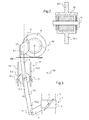
figure 1 est une vue schématique d'ensemble d'un mode de réalisation particulier du dispositif selon l'invention, l'actionneur selon l'invention fermant une vanne telle qu'une vanne de régulation de la pression de suralimentation; - la
figure 2 est une vue de détail schématique du système de guidage selon le mode de réalisation précèdent ; - la
figure 3 est une vue schématique d'ensemble du mode de réalisation de lafigure 1 , l'actionneur selon l'invention ouvrant une vanne telle qu'une vanne de régulation de la pression de suralimentation.
- the
figure 1 is a schematic overview of a particular embodiment of the device according to the invention, the actuator according to the invention closing a valve such as a valve for regulating the boost pressure; - the
figure 2 is a schematic detail view of the guidance system according to the preceding embodiment; - the
figure 3 is a schematic overview of the embodiment of thefigure 1 , the actuator according to the invention opening a valve such as a valve for regulating the boost pressure.
Les
La vanne 1, connue en elle-même, comprend un corps qui est monté sur une conduite de contournement de la turbine d'un dispositif de suralimentation du véhicule à moteur à combustion interne et qui reçoit à pivotement un arbre 3 porteur d'un papillon 4. L'arbre 3 a une extrémité en saillie du corps de la vanne 1 qui est liée en rotation à une manivelle 5 permettant l'actionnement du papillon 4 depuis l'extérieur du corps. En variante, le papillon 4 peut être remplacé par une soupape ou un clapet.The valve 1, known in itself, comprises a body which is mounted on a bypass line of the turbine of a supercharging device of the internal combustion engine vehicle and which receives a pivotally a The
L'actionneur 60 comprend un moteur électrique 6 solidaire d'un bâti 100. Le moteur électrique 6 entraîne un engrenage composé d'une première roue dentée 7 liée à l'arbre de sortie du moteur électrique 6 et qui engrène avec la denture d'un secteur denté 8 de diamètre supérieur à celui de la roue dentée 7, réalisant ainsi une réduction de la vitesse de rotation du moteur électrique 6. Le secteur denté 8 est monté sur le bâti 100 pour pivoter autour d'un axe de rotation Y parallèle à l'axe de rotation du moteur 6 et est pourvu d'un maneton pour former un plateau manivelle manoeuvrant une bielle de commande 9 se déplaçant selon une direction de translation X qui s'étend dans un plan normal à l'axe de rotation du moteur 6. La bielle de commande 9 est liée en une de ses extrémités 9.1 à un arbre, parallèle à l'axe Y, positionné à proximité de la denture du secteur denté 8 autour duquel la bielle de commande peut pivoter. L'autre extrémité 9.2 de la bielle de commande 9 a un profil en forme de fourche. Les deux branches de cette fourche coopèrent avec un profil similaire plus étroit réalisé en une première extrémité 10.1 de l'organe à déplacer linéairement, ici une tige de manoeuvre 10. Un arbre 11 coopère avec un alésage réalisé au travers des branches des fourches des extrémités 9.2 de la bielle de commande 9 et 10.1 de la tige de manoeuvre 10, réalisant ainsi une liaison pivot d'axe parallèle à l'axe Y entre ces deux éléments. Un galet de guidage 12 est monté sur l'arbre 11 entre les fourches des extrémités 9.2 de la bielle de commande 9 et 10.1 de la tige de manoeuvre 10. Avantageusement le galet de guidage 12 est un roulement à billes dont la cage extérieure fait office de bande de roulement. Ce galet de guidage 12 roule sur une voie de roulement 13 liée au bâti 100. Cette voie est constituée, ici, de deux surfaces planes 13.1 et 13.2 s'étendant parallèlement à un plan contenant la direction de translation X et parallèle à l'axe de rotation Y du secteur denté 8. La distance séparant les deux surfaces 13.1 et 13.2 comprend un jeu de fonctionnement adapté au roulement du galet de guidage 12 sur une seule des deux surfaces lors de son déplacement. La jonction de l'extrémité 10.2 de la tige de manoeuvre 10 avec la manivelle 5 de la vanne papillon 1 est une liaison pivot 14 qui autorise une inclinaison de la tige 10 relativement à la manivelle 5 autour d'un axe parallèle à l'axe transversal Y. Cette liaison est réalisée par des moyens connus de l'homme du métier tel qu'un arbre épaulé traversant les deux pièces 10 et 5.The
En fonctionnement, le déplacement de l'extrémité de la manivelle 5 liée à l'extrémité 10.2 de la tige de manoeuvre 10 se fait selon un arc de cercle dont le centre se situe sur l'axe de l'arbre 3. Lorsqu'une tension est appliquée aux bornes du moteur électrique 6, la rotation de l'arbre de sortie du moteur 6 entraîne la rotation du secteur denté 8 avec un rapport de réduction de vitesse équivalent au rapport des diamètres de la roue dentée 7 et du secteur denté 8. La rotation du secteur denté 8 entraîne le déplacement de l'extrémité 9.2 de la bielle de commande 9. Le galet de guidage 12 lié à cette extrémité roule sur une des surfaces de la voie de roulement 13 assurant un guidage suivant la direction de translation X de l'extrémité 9.2 de la bielle de commande, elle-même liée à l'extrémité 10.1 de la tige de commande 10. Lors du déplacement de la tige 10, son extrémité 10.2 liée à la manivelle 5 se déplace selon la direction de translation X mais également selon une direction comprise dans un plan normal à cette direction X. Ce déplacement est rendu possible par le pivot d'axe parallèle à Y, réalisé par l'arbre 11 entre la bielle de manoeuvre 9 et la tige de commande 10.In operation, the displacement of the end of the
On obtient donc un guidage de la tige de commande 10 faisant appel au roulement du galet de guidage 12 sur l'une ou l'autre des voies de roulement 13. Ce guidage autorise un degré de liberté en rotation de la tige 10 relativement à la bielle 9 autour d'un axe parallèle à l'axe Y de rotation du secteur denté 8. Ce degré de liberté est avantageusement mis à profit dans le cas d'un actionneur lié au papillon ou au clapet d'une vanne de régulation de la pression de suralimentation car il permet de supprimer la bielle de manoeuvre nécessaire dans les solutions de l'art antérieur et ainsi de réduire les coûts de production d'un tel équipement.We thus obtain a guide of the
Bien entendu, l'invention n'est pas limitée aux modes de réalisation décrits mais englobe toute variante entrant dans le champ de l'invention telle que définie par les revendications. En particulier,
- bien que la réduction de la rotation de l'arbre de sortie du moteur 6 soit faite par un unique engrenage, l'invention s'applique également à une réduction réalisée par un train d'engrenage constitué de plusieurs roues dentées successives ;
- bien que le guidage de la tige 10 soit réalisé par un galet de guidage 12 roulant sur une voie de roulement 13 comprenant deux surfaces de roulement, l'invention s'applique également à une voie de roulement comprenant une unique surface de roulement ;
- bien que les extrémités en liaison de l'organe à déplacer linéairement, ici une tige 10, et de la bielle de commande 9 aient un profil en fourche, l'invention s'applique également à d'autres jonctions comme par exemple une jonction plat sur plat.
- although the reduction of the rotation of the output shaft of the
motor 6 is made by a single gear, the invention also applies to a reduction made by a gear train consisting of several successive gear wheels; - although the
guide rod 10 is formed by aguide roller 12 rolling on araceway 13 comprising two rolling surfaces, the invention also applies to a raceway comprising a single running surface; - although the ends in connection with the linearly moving member, here a
rod 10, and thecontrol rod 9 have a fork profile, the invention also applies to other junctions such as for example a flat junction on flat.
Claims (4)
Applications Claiming Priority (1)
| Application Number | Priority Date | Filing Date | Title |
|---|---|---|---|
| FR1162185A FR2984955B1 (en) | 2011-12-21 | 2011-12-21 | MOTOR CONTROL ACTUATOR WITH ROD-CRANK MECHANISM |
Publications (2)
| Publication Number | Publication Date |
|---|---|
| EP2607646A1 true EP2607646A1 (en) | 2013-06-26 |
| EP2607646B1 EP2607646B1 (en) | 2014-05-21 |
Family
ID=47355958
Family Applications (1)
| Application Number | Title | Priority Date | Filing Date |
|---|---|---|---|
| EP12197851.4A Not-in-force EP2607646B1 (en) | 2011-12-21 | 2012-12-18 | Actuator for controlling an engine with a crank-bar mechanism |
Country Status (2)
| Country | Link |
|---|---|
| EP (1) | EP2607646B1 (en) |
| FR (1) | FR2984955B1 (en) |
Cited By (1)
| Publication number | Priority date | Publication date | Assignee | Title |
|---|---|---|---|---|
| EP4089269A1 (en) * | 2021-05-11 | 2022-11-16 | Garrett Transportation I Inc. | Turbocharger bypass valve and actuator assembly therefor having guided toggle |
Families Citing this family (1)
| Publication number | Priority date | Publication date | Assignee | Title |
|---|---|---|---|---|
| FR3127796B1 (en) * | 2021-10-01 | 2024-02-16 | Valeo Systemes De Controle Moteur | System for actuating a mobile member |
Citations (5)
| Publication number | Priority date | Publication date | Assignee | Title |
|---|---|---|---|---|
| EP1028249A2 (en) * | 1999-02-12 | 2000-08-16 | Eaton Corporation | EGR system and improved actuator therefor |
| WO2002095209A1 (en) * | 2001-05-23 | 2002-11-28 | Siemens Aktiengesellschaft | Device for preventing an exhaust gas recirculation valve from sticking after switching off an internal combustion engine |
| WO2007059100A1 (en) * | 2005-11-14 | 2007-05-24 | Borgwarner Inc. | Actuator with integrated drive mechanism |
| WO2007138480A2 (en) * | 2006-05-31 | 2007-12-06 | Toyota Jidosha Kabushiki Kaisha | Actuator for automobiles |
| DE102007054769A1 (en) * | 2007-11-16 | 2009-05-20 | Bosch Mahle Turbo Systems Gmbh & Co. Kg | Actuator for bidirectional actuator |
-
2011
- 2011-12-21 FR FR1162185A patent/FR2984955B1/en not_active Expired - Fee Related
-
2012
- 2012-12-18 EP EP12197851.4A patent/EP2607646B1/en not_active Not-in-force
Patent Citations (5)
| Publication number | Priority date | Publication date | Assignee | Title |
|---|---|---|---|---|
| EP1028249A2 (en) * | 1999-02-12 | 2000-08-16 | Eaton Corporation | EGR system and improved actuator therefor |
| WO2002095209A1 (en) * | 2001-05-23 | 2002-11-28 | Siemens Aktiengesellschaft | Device for preventing an exhaust gas recirculation valve from sticking after switching off an internal combustion engine |
| WO2007059100A1 (en) * | 2005-11-14 | 2007-05-24 | Borgwarner Inc. | Actuator with integrated drive mechanism |
| WO2007138480A2 (en) * | 2006-05-31 | 2007-12-06 | Toyota Jidosha Kabushiki Kaisha | Actuator for automobiles |
| DE102007054769A1 (en) * | 2007-11-16 | 2009-05-20 | Bosch Mahle Turbo Systems Gmbh & Co. Kg | Actuator for bidirectional actuator |
Cited By (1)
| Publication number | Priority date | Publication date | Assignee | Title |
|---|---|---|---|---|
| EP4089269A1 (en) * | 2021-05-11 | 2022-11-16 | Garrett Transportation I Inc. | Turbocharger bypass valve and actuator assembly therefor having guided toggle |
Also Published As
| Publication number | Publication date |
|---|---|
| EP2607646B1 (en) | 2014-05-21 |
| FR2984955B1 (en) | 2014-03-07 |
| FR2984955A1 (en) | 2013-06-28 |
Similar Documents
| Publication | Publication Date | Title |
|---|---|---|
| EP2516891B1 (en) | Device for converting rotational movement into translational movement | |
| EP2516835B1 (en) | Method for controlling an egr circuit in a motor vehicle engine | |
| EP1040266B1 (en) | Control valve for recirculation system of an internal combustion engine exhaust gases | |
| EP2010770A1 (en) | Air intake device for a heat engine with a cooled main circulation system and a bypass system equipped with a heating mechanism | |
| KR20130087381A (en) | Actuating drive, exhaust gas recirculating valve, turbocharger | |
| EP2783097B1 (en) | Control valve for an internal combustion engine exhaust gas recirculation system | |
| EP2607646B1 (en) | Actuator for controlling an engine with a crank-bar mechanism | |
| FR2950862A1 (en) | DEVICE FOR CONTROLLING GASES OF AN AIRCRAFT, INCORPORATING A CONNECTION BY CAMS | |
| FR2988797A1 (en) | ELECTROMECHANICAL FLOATING SURFACE ACTUATOR FOR AIRCRAFT AND AIRCRAFT PROVIDED WITH SUCH AN ACTUATOR | |
| EP3027863B1 (en) | Electromagnetic actuator for controlling the waste gate of a turbocharger | |
| EP2344725B1 (en) | System for controlling variable geometry equipment of a gas turbine engine especially comprising a guiding track connection | |
| EP2607644B1 (en) | Rack and pinion control actuator | |
| FR2927975A1 (en) | Valve i.e. three-way valve, for exhaust line of motor vehicle, has connection unit connecting driving and driven units such that rotational displacement of driving unit around axis provokes displacement of driven unit around another axis | |
| FR2748780A1 (en) | VALVE FOR INTERNAL COMBUSTION ENGINE EXHAUST GAS RECIRCULATION SYSTEM | |
| FR2940395A3 (en) | Controllable valve for circular sectioned cylindrical air duct of petrol engine of motor vehicle, has return unit comprising two magnetic elements, where default position of valve corresponds to optimal alignment of two magnetic elements | |
| EP3186496B1 (en) | Assembly for an air circuit of a heat engine | |
| FR2756322A1 (en) | DEVICE FOR CONTROLLING A SAFETY VALVE FOR MOTORS WITH TURBOCHARGER PRESSURE MECHANISM | |
| EP1548250A1 (en) | Internal combustion engine with controlled supercharging and method for controlling the supercharging | |
| FR3127796A1 (en) | System for actuating a moving part | |
| WO2016170292A1 (en) | Air pipe valve of an engine of a motor vehicle | |
| FR2845732A1 (en) | Control system for recirculation of i.c. engine exhaust gases comprises central computer calculating recorded gas recirculation value as function of engine operating point and control part for exhaust gas recirculation valve displacement | |
| WO2008084142A1 (en) | Electromagnetic actuator having reduced guiding portions | |
| FR2782746A1 (en) | DEVICE FOR CONTROLLING A DISCHARGE VALVE | |
| FR3045768A1 (en) | VALVE FOR MONITORING FLUID FLOW | |
| FR2994239A1 (en) | Control mechanism for thrust of clutch of car, has cam provided with respect to moving element between retracted position and engaged position, where reaction force is applied to cam by lever to reduce contact angle |
Legal Events
| Date | Code | Title | Description |
|---|---|---|---|
| AK | Designated contracting states |
Kind code of ref document: A1 Designated state(s): AL AT BE BG CH CY CZ DE DK EE ES FI FR GB GR HR HU IE IS IT LI LT LU LV MC MK MT NL NO PL PT RO RS SE SI SK SM TR |
|
| AX | Request for extension of the european patent |
Extension state: BA ME |
|
| PUAI | Public reference made under article 153(3) epc to a published international application that has entered the european phase |
Free format text: ORIGINAL CODE: 0009012 |
|
| 17P | Request for examination filed |
Effective date: 20131217 |
|
| RBV | Designated contracting states (corrected) |
Designated state(s): AL AT BE BG CH CY CZ DE DK EE ES FI FR GB GR HR HU IE IS IT LI LT LU LV MC MK MT NL NO PL PT RO RS SE SI SK SM TR |
|
| GRAP | Despatch of communication of intention to grant a patent |
Free format text: ORIGINAL CODE: EPIDOSNIGR1 |
|
| RIC1 | Information provided on ipc code assigned before grant |
Ipc: F16K 31/04 20060101ALI20140128BHEP Ipc: F02M 25/07 20060101ALI20140128BHEP Ipc: F02B 37/24 20060101AFI20140128BHEP Ipc: F16K 31/53 20060101ALI20140128BHEP Ipc: F16K 31/52 20060101ALI20140128BHEP Ipc: F02B 37/18 20060101ALI20140128BHEP |
|
| INTG | Intention to grant announced |
Effective date: 20140220 |
|
| GRAS | Grant fee paid |
Free format text: ORIGINAL CODE: EPIDOSNIGR3 |
|
| GRAA | (expected) grant |
Free format text: ORIGINAL CODE: 0009210 |
|
| AK | Designated contracting states |
Kind code of ref document: B1 Designated state(s): AL AT BE BG CH CY CZ DE DK EE ES FI FR GB GR HR HU IE IS IT LI LT LU LV MC MK MT NL NO PL PT RO RS SE SI SK SM TR |
|
| REG | Reference to a national code |
Ref country code: GB Ref legal event code: FG4D Free format text: NOT ENGLISH |
|
| REG | Reference to a national code |
Ref country code: CH Ref legal event code: EP |
|
| REG | Reference to a national code |
Ref country code: AT Ref legal event code: REF Ref document number: 669727 Country of ref document: AT Kind code of ref document: T Effective date: 20140615 |
|
| REG | Reference to a national code |
Ref country code: IE Ref legal event code: FG4D Free format text: LANGUAGE OF EP DOCUMENT: FRENCH |
|
| REG | Reference to a national code |
Ref country code: DE Ref legal event code: R096 Ref document number: 602012001885 Country of ref document: DE Effective date: 20140710 |
|
| REG | Reference to a national code |
Ref country code: AT Ref legal event code: MK05 Ref document number: 669727 Country of ref document: AT Kind code of ref document: T Effective date: 20140521 Ref country code: NL Ref legal event code: VDEP Effective date: 20140521 |
|
| REG | Reference to a national code |
Ref country code: LT Ref legal event code: MG4D |
|
| PG25 | Lapsed in a contracting state [announced via postgrant information from national office to epo] |
Ref country code: GR Free format text: LAPSE BECAUSE OF FAILURE TO SUBMIT A TRANSLATION OF THE DESCRIPTION OR TO PAY THE FEE WITHIN THE PRESCRIBED TIME-LIMIT Effective date: 20140822 Ref country code: IS Free format text: LAPSE BECAUSE OF FAILURE TO SUBMIT A TRANSLATION OF THE DESCRIPTION OR TO PAY THE FEE WITHIN THE PRESCRIBED TIME-LIMIT Effective date: 20140921 Ref country code: LT Free format text: LAPSE BECAUSE OF FAILURE TO SUBMIT A TRANSLATION OF THE DESCRIPTION OR TO PAY THE FEE WITHIN THE PRESCRIBED TIME-LIMIT Effective date: 20140521 Ref country code: NO Free format text: LAPSE BECAUSE OF FAILURE TO SUBMIT A TRANSLATION OF THE DESCRIPTION OR TO PAY THE FEE WITHIN THE PRESCRIBED TIME-LIMIT Effective date: 20140821 Ref country code: FI Free format text: LAPSE BECAUSE OF FAILURE TO SUBMIT A TRANSLATION OF THE DESCRIPTION OR TO PAY THE FEE WITHIN THE PRESCRIBED TIME-LIMIT Effective date: 20140521 |
|
| PG25 | Lapsed in a contracting state [announced via postgrant information from national office to epo] |
Ref country code: LV Free format text: LAPSE BECAUSE OF FAILURE TO SUBMIT A TRANSLATION OF THE DESCRIPTION OR TO PAY THE FEE WITHIN THE PRESCRIBED TIME-LIMIT Effective date: 20140521 Ref country code: AT Free format text: LAPSE BECAUSE OF FAILURE TO SUBMIT A TRANSLATION OF THE DESCRIPTION OR TO PAY THE FEE WITHIN THE PRESCRIBED TIME-LIMIT Effective date: 20140521 Ref country code: SE Free format text: LAPSE BECAUSE OF FAILURE TO SUBMIT A TRANSLATION OF THE DESCRIPTION OR TO PAY THE FEE WITHIN THE PRESCRIBED TIME-LIMIT Effective date: 20140521 Ref country code: ES Free format text: LAPSE BECAUSE OF FAILURE TO SUBMIT A TRANSLATION OF THE DESCRIPTION OR TO PAY THE FEE WITHIN THE PRESCRIBED TIME-LIMIT Effective date: 20140521 Ref country code: HR Free format text: LAPSE BECAUSE OF FAILURE TO SUBMIT A TRANSLATION OF THE DESCRIPTION OR TO PAY THE FEE WITHIN THE PRESCRIBED TIME-LIMIT Effective date: 20140521 Ref country code: PL Free format text: LAPSE BECAUSE OF FAILURE TO SUBMIT A TRANSLATION OF THE DESCRIPTION OR TO PAY THE FEE WITHIN THE PRESCRIBED TIME-LIMIT Effective date: 20140521 Ref country code: RS Free format text: LAPSE BECAUSE OF FAILURE TO SUBMIT A TRANSLATION OF THE DESCRIPTION OR TO PAY THE FEE WITHIN THE PRESCRIBED TIME-LIMIT Effective date: 20140521 |
|
| PG25 | Lapsed in a contracting state [announced via postgrant information from national office to epo] |
Ref country code: PT Free format text: LAPSE BECAUSE OF FAILURE TO SUBMIT A TRANSLATION OF THE DESCRIPTION OR TO PAY THE FEE WITHIN THE PRESCRIBED TIME-LIMIT Effective date: 20140922 |
|
| PG25 | Lapsed in a contracting state [announced via postgrant information from national office to epo] |
Ref country code: CZ Free format text: LAPSE BECAUSE OF FAILURE TO SUBMIT A TRANSLATION OF THE DESCRIPTION OR TO PAY THE FEE WITHIN THE PRESCRIBED TIME-LIMIT Effective date: 20140521 Ref country code: DK Free format text: LAPSE BECAUSE OF FAILURE TO SUBMIT A TRANSLATION OF THE DESCRIPTION OR TO PAY THE FEE WITHIN THE PRESCRIBED TIME-LIMIT Effective date: 20140521 Ref country code: RO Free format text: LAPSE BECAUSE OF FAILURE TO SUBMIT A TRANSLATION OF THE DESCRIPTION OR TO PAY THE FEE WITHIN THE PRESCRIBED TIME-LIMIT Effective date: 20140521 Ref country code: SK Free format text: LAPSE BECAUSE OF FAILURE TO SUBMIT A TRANSLATION OF THE DESCRIPTION OR TO PAY THE FEE WITHIN THE PRESCRIBED TIME-LIMIT Effective date: 20140521 Ref country code: EE Free format text: LAPSE BECAUSE OF FAILURE TO SUBMIT A TRANSLATION OF THE DESCRIPTION OR TO PAY THE FEE WITHIN THE PRESCRIBED TIME-LIMIT Effective date: 20140521 |
|
| REG | Reference to a national code |
Ref country code: DE Ref legal event code: R097 Ref document number: 602012001885 Country of ref document: DE |
|
| PG25 | Lapsed in a contracting state [announced via postgrant information from national office to epo] |
Ref country code: NL Free format text: LAPSE BECAUSE OF FAILURE TO SUBMIT A TRANSLATION OF THE DESCRIPTION OR TO PAY THE FEE WITHIN THE PRESCRIBED TIME-LIMIT Effective date: 20140521 |
|
| PLBE | No opposition filed within time limit |
Free format text: ORIGINAL CODE: 0009261 |
|
| STAA | Information on the status of an ep patent application or granted ep patent |
Free format text: STATUS: NO OPPOSITION FILED WITHIN TIME LIMIT |
|
| 26N | No opposition filed |
Effective date: 20150224 |
|
| REG | Reference to a national code |
Ref country code: DE Ref legal event code: R097 Ref document number: 602012001885 Country of ref document: DE Effective date: 20150224 |
|
| PG25 | Lapsed in a contracting state [announced via postgrant information from national office to epo] |
Ref country code: BE Free format text: LAPSE BECAUSE OF NON-PAYMENT OF DUE FEES Effective date: 20141231 |
|
| PG25 | Lapsed in a contracting state [announced via postgrant information from national office to epo] |
Ref country code: SI Free format text: LAPSE BECAUSE OF FAILURE TO SUBMIT A TRANSLATION OF THE DESCRIPTION OR TO PAY THE FEE WITHIN THE PRESCRIBED TIME-LIMIT Effective date: 20140521 Ref country code: LU Free format text: LAPSE BECAUSE OF FAILURE TO SUBMIT A TRANSLATION OF THE DESCRIPTION OR TO PAY THE FEE WITHIN THE PRESCRIBED TIME-LIMIT Effective date: 20141218 |
|
| REG | Reference to a national code |
Ref country code: IE Ref legal event code: MM4A |
|
| PG25 | Lapsed in a contracting state [announced via postgrant information from national office to epo] |
Ref country code: IE Free format text: LAPSE BECAUSE OF NON-PAYMENT OF DUE FEES Effective date: 20141218 |
|
| REG | Reference to a national code |
Ref country code: FR Ref legal event code: PLFP Year of fee payment: 4 |
|
| PG25 | Lapsed in a contracting state [announced via postgrant information from national office to epo] |
Ref country code: MC Free format text: LAPSE BECAUSE OF FAILURE TO SUBMIT A TRANSLATION OF THE DESCRIPTION OR TO PAY THE FEE WITHIN THE PRESCRIBED TIME-LIMIT Effective date: 20140521 |
|
| PG25 | Lapsed in a contracting state [announced via postgrant information from national office to epo] |
Ref country code: CY Free format text: LAPSE BECAUSE OF FAILURE TO SUBMIT A TRANSLATION OF THE DESCRIPTION OR TO PAY THE FEE WITHIN THE PRESCRIBED TIME-LIMIT Effective date: 20140521 Ref country code: BG Free format text: LAPSE BECAUSE OF FAILURE TO SUBMIT A TRANSLATION OF THE DESCRIPTION OR TO PAY THE FEE WITHIN THE PRESCRIBED TIME-LIMIT Effective date: 20140521 |
|
| PG25 | Lapsed in a contracting state [announced via postgrant information from national office to epo] |
Ref country code: MT Free format text: LAPSE BECAUSE OF FAILURE TO SUBMIT A TRANSLATION OF THE DESCRIPTION OR TO PAY THE FEE WITHIN THE PRESCRIBED TIME-LIMIT Effective date: 20140521 Ref country code: TR Free format text: LAPSE BECAUSE OF FAILURE TO SUBMIT A TRANSLATION OF THE DESCRIPTION OR TO PAY THE FEE WITHIN THE PRESCRIBED TIME-LIMIT Effective date: 20140521 Ref country code: HU Free format text: LAPSE BECAUSE OF FAILURE TO SUBMIT A TRANSLATION OF THE DESCRIPTION OR TO PAY THE FEE WITHIN THE PRESCRIBED TIME-LIMIT; INVALID AB INITIO Effective date: 20121218 |
|
| REG | Reference to a national code |
Ref country code: CH Ref legal event code: PL |
|
| PG25 | Lapsed in a contracting state [announced via postgrant information from national office to epo] |
Ref country code: LI Free format text: LAPSE BECAUSE OF NON-PAYMENT OF DUE FEES Effective date: 20151231 Ref country code: CH Free format text: LAPSE BECAUSE OF NON-PAYMENT OF DUE FEES Effective date: 20151231 |
|
| REG | Reference to a national code |
Ref country code: FR Ref legal event code: PLFP Year of fee payment: 5 |
|
| PG25 | Lapsed in a contracting state [announced via postgrant information from national office to epo] |
Ref country code: SM Free format text: LAPSE BECAUSE OF FAILURE TO SUBMIT A TRANSLATION OF THE DESCRIPTION OR TO PAY THE FEE WITHIN THE PRESCRIBED TIME-LIMIT Effective date: 20140521 |
|
| REG | Reference to a national code |
Ref country code: FR Ref legal event code: PLFP Year of fee payment: 6 |
|
| PGFP | Annual fee paid to national office [announced via postgrant information from national office to epo] |
Ref country code: GB Payment date: 20171219 Year of fee payment: 6 Ref country code: IT Payment date: 20171214 Year of fee payment: 6 |
|
| PG25 | Lapsed in a contracting state [announced via postgrant information from national office to epo] |
Ref country code: MK Free format text: LAPSE BECAUSE OF FAILURE TO SUBMIT A TRANSLATION OF THE DESCRIPTION OR TO PAY THE FEE WITHIN THE PRESCRIBED TIME-LIMIT Effective date: 20140521 |
|
| PG25 | Lapsed in a contracting state [announced via postgrant information from national office to epo] |
Ref country code: AL Free format text: LAPSE BECAUSE OF FAILURE TO SUBMIT A TRANSLATION OF THE DESCRIPTION OR TO PAY THE FEE WITHIN THE PRESCRIBED TIME-LIMIT Effective date: 20140521 |
|
| PGFP | Annual fee paid to national office [announced via postgrant information from national office to epo] |
Ref country code: DE Payment date: 20181211 Year of fee payment: 7 |
|
| PGFP | Annual fee paid to national office [announced via postgrant information from national office to epo] |
Ref country code: FR Payment date: 20181231 Year of fee payment: 7 |
|
| GBPC | Gb: european patent ceased through non-payment of renewal fee |
Effective date: 20181218 |
|
| PG25 | Lapsed in a contracting state [announced via postgrant information from national office to epo] |
Ref country code: IT Free format text: LAPSE BECAUSE OF NON-PAYMENT OF DUE FEES Effective date: 20181218 |
|
| PG25 | Lapsed in a contracting state [announced via postgrant information from national office to epo] |
Ref country code: GB Free format text: LAPSE BECAUSE OF NON-PAYMENT OF DUE FEES Effective date: 20181218 |
|
| REG | Reference to a national code |
Ref country code: DE Ref legal event code: R119 Ref document number: 602012001885 Country of ref document: DE |
|
| PG25 | Lapsed in a contracting state [announced via postgrant information from national office to epo] |
Ref country code: FR Free format text: LAPSE BECAUSE OF NON-PAYMENT OF DUE FEES Effective date: 20191231 Ref country code: DE Free format text: LAPSE BECAUSE OF NON-PAYMENT OF DUE FEES Effective date: 20200701 |