EP2607211A2 - Nutzfahrzeug mit einem modularen Fahrgestellrahmen, dessen Längsträger durch Querträger verbunden sind - Google Patents
Nutzfahrzeug mit einem modularen Fahrgestellrahmen, dessen Längsträger durch Querträger verbunden sind Download PDFInfo
- Publication number
- EP2607211A2 EP2607211A2 EP12400036.5A EP12400036A EP2607211A2 EP 2607211 A2 EP2607211 A2 EP 2607211A2 EP 12400036 A EP12400036 A EP 12400036A EP 2607211 A2 EP2607211 A2 EP 2607211A2
- Authority
- EP
- European Patent Office
- Prior art keywords
- shoe
- chassis frame
- commercial vehicle
- connection
- vehicle according
- Prior art date
- Legal status (The legal status is an assumption and is not a legal conclusion. Google has not performed a legal analysis and makes no representation as to the accuracy of the status listed.)
- Granted
Links
Images






Classifications
-
- B—PERFORMING OPERATIONS; TRANSPORTING
- B62—LAND VEHICLES FOR TRAVELLING OTHERWISE THAN ON RAILS
- B62D—MOTOR VEHICLES; TRAILERS
- B62D21/00—Understructures, i.e. chassis frame on which a vehicle body may be mounted
- B62D21/02—Understructures, i.e. chassis frame on which a vehicle body may be mounted comprising longitudinally or transversely arranged frame members
-
- B—PERFORMING OPERATIONS; TRANSPORTING
- B62—LAND VEHICLES FOR TRAVELLING OTHERWISE THAN ON RAILS
- B62D—MOTOR VEHICLES; TRAILERS
- B62D21/00—Understructures, i.e. chassis frame on which a vehicle body may be mounted
- B62D21/12—Understructures, i.e. chassis frame on which a vehicle body may be mounted assembled from readily detachable parts
-
- B—PERFORMING OPERATIONS; TRANSPORTING
- B62—LAND VEHICLES FOR TRAVELLING OTHERWISE THAN ON RAILS
- B62D—MOTOR VEHICLES; TRAILERS
- B62D21/00—Understructures, i.e. chassis frame on which a vehicle body may be mounted
- B62D21/17—Understructures, i.e. chassis frame on which a vehicle body may be mounted forming fluid or electrical conduit means or having other means to accommodate the transmission of a force or signal
Definitions
- the invention relates to a utility vehicle with a chassis frame comprising longitudinal members connected by cross members, which are each interconnected by a respective connecting shoe, wherein the chassis frame is composed of individual modules.
- the chassis frame forms the basis for the chassis of a commercial vehicle. It picks up all axles and the entire powertrain with the engine and transmission. In addition, he wears the cab and the existing bodies.
- the chassis frame of a commercial vehicle usually comprises two longitudinal members, which are connected by a plurality of mutually parallel cross member. Since a tractor can be combined with a cab mounted on the chassis frame with various superstructures, it is common today in truck and bus construction to divide the vehicle frame into a front, a center and a rear module. Depending on the purpose for which the respective commercial vehicle is intended, prefabricated front and rear modules can be combined with each other. For connecting the front and rear modules, at least one center module can be arranged between the two modules.
- the respective modules are fastened to each other in the region of the longitudinal members by connecting shoes. Due to the high axle loads of the front and rear modules rigid axles have become popular in today's commercial vehicles. Among the most important components of the suspension of such axles include the so-called wishbones. They connect the wheel or axle guide with the chassis frame and thus absorb the wheel or axle guiding forces. It is conceivable here, for example, transverse and wishbone. However, trailing arms are used in combination with the air suspension, the trailing arm usually only takes over forces in the longitudinal direction. Both in the connection of each abutting side members of the front, center and rear modules as well as the connection of the wishbone to the frame rails are multifunction bearing blocks used.
- a trailing arm which is arranged on a frame longitudinal member of a commercial vehicle and means for supporting and supporting trailing arms and at least one stabilizer.
- the trailing arm block has means for supporting and supporting triangular links and at least one bulge for partially encompassing receiving the end region of the Torosionsabiteses.
- the Torosionsabterrorism belongs to at least one, transverse to the trough stabilizer.
- the Ausmuldung cooperates with a, the stabilizer partially encompassing holding sleeve.
- the frame consists of several prefabricated or pre-assembled modules, each of which consists of two, connected by at least one cross member longitudinal sections.
- the longitudinal beam sections of two adjoining frame modules are arranged in alignment with one another in the frame final assembly and are connected to one another via a cross member serving as a longitudinal and transverse connecting member.
- the cross member bridges with its connecting members, which are provided at both ends, the respective butt joint between two modules.
- the disadvantage is that in today's chassis frame, the electrical lines, the compressed air line and other lines that serve the water or the fuel supply are often located on the underside of the chassis frame of a truck or a bus. As a rule, the lines are delivered without damage due to stones being thrown up or splashed water.
- the commercial vehicle according to the invention comprises a chassis frame whose longitudinal members are connected by a plurality of cross members with each other and which is composed of individual modules.
- the individual modules can be relative to the vehicle longitudinal direction on a uniform or at different height levels are located.
- the respective longitudinal abutting individual modules of the chassis frame are interconnected by connecting shoes.
- the respective connecting shoe extends axially parallel to the vehicle longitudinal axis.
- the connecting shoes have a kink to compensate for the height level in the longitudinal direction.
- the front module is located in the area of a conventional commercial vehicle in the area of the driver's workplace and includes the engine, the transmission and at least one axle.
- the rear module comprises the at least one rear axle of the bus or the truck.
- the front and the rear module are each connected to each other by at least one center module, which is at least a center module often placed lower relative to the front and rear module especially for buses that are used in local traffic.
- the connection shoes can be made depending on the size and weight of the commercial vehicle as cast or forged parts.
- connection shoe bridges a horizontal and / or vertical frame offset between the side member modules in the tightest of spaces.
- further cross members are arranged on the outside of the connecting shoe on this or on the longitudinal member, which serve for example to support the body of the vehicle.
- the other cross member may be made as a C-profile or in tube form.
- the cross member is attached approximately at right angles to the vehicle longitudinal axis on the outside of the connecting shoe and can be bolted to the side member or with the connection shoe, riveted or made in one piece with said components. If a further stiffening of the body is required, two further cross members can be arranged on the outside of a connecting shoe.
- the side members, the cross member and the other cross member are each formed as a C-profile. However, all other profile shapes used in vehicle construction are also conceivable.
- Pipelines for fluids, electrical lines or pipes for the compressed air supply run in the commercial vehicle along the longitudinal and the cross member. To connect individual line elements with each other expansion pieces, seals, flanges and sleeves are provided.
- the separation points of the individual modules must be given special consideration when laying the supply lines. From manufacturing and For assembly purposes, the separation points of the supply lines must match the separation points of the modules.
- the supply lines are thereby captively secured to the longitudinal and transverse beams of the chassis frame. According to the invention, it is provided to integrate the supply lines in the connection shoes.
- connection shoe not only forms the separation point between the individual modules of the chassis frame, but also forms the interface for the fuel, hydraulic and pneumatic supply lines.
- the connection shoe according to the invention has a standardized hole pattern for connection to other components.
- the hole pattern can be designed, for example, symmetrically or asymmetrically on the individual flange surfaces, so that a component to be connected can be installed rotated about its longitudinal axis.
- the advantage is that in this way an offset of the component in the opposite direction can be realized.
- a further embodiment of the invention provides that the connecting element is integrally formed on the connecting shoe.
- the connection shoe can be positively, positively and materially connected to the connecting element. By eliminating additional fasteners, the manufacturing cost of the vehicle can be reduced.
- the connecting element is a piece of pipe integrated in the connecting shoe.
- a coupling is provided, which allows a connection to a guided on the chassis frame line.
- the pipe sections can be insulated for the passage of electrical lines or have insulating plastic inlays.
- the couplings are standardized and thus allow a mutual connection of the cables to the chassis frame.
- a further embodiment of the invention provides that the connecting element is an electrical conductor element integrated in the connecting shoe, which can be connected to an electrical line guided on the chassis frame.
- the connecting element is a holder arranged on the connection shoe, which serves for fastening a plurality of lines and thereby bridges the connection region between two abutting modules.
- the holder may be formed as a clamping bush.
- the connecting element comprises in each case at least two plug-in elements which communicate with one another, of which one is arranged on the connecting shoe and the other is fastened on the connecting line. The assembly or disassembly of the connection shoe on / from the longitudinal or cross member for repair or maintenance is much easier in this way.
- connection element has the form of a socket into which a tubular connecting piece of a component to be fastened to the chassis frame can be inserted.
- the stabilizer can be arranged in a voltage-optimized position on the chassis frame, in which a direct power flow is ensured in the component.
- the connection shoe is equipped with at least one mounting flange for a stabilizer bearing.
- the connecting flanges 10 extend; 28; 29 of the connection shoe 1 relative to the vehicle longitudinal direction 6 vertically and horizontally offset from one another.
- Fig. 4 are the connecting flanges 10; 28; 29 arranged offset relative to the vehicle longitudinal direction 6 horizontally to each other.
- the connecting flanges 10; 28 of the connection shoe 1 uniform hole patterns 11. In this way, the connecting shoe 1 is rotatable as a standard part about its longitudinal axis and its attachment relative to the vehicle longitudinal direction 6 on both sides of the chassis frame 4 on the longitudinal members 2 (not shown) possible.
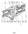
- FIG. 1 shows a connecting shoe 1, which connects two longitudinal members 2 of a module 3 of a chassis frame 4 of a commercial vehicle 5 with each other.
- the connection shoe 1 has in the vehicle longitudinal direction 6 a kink 7, with which the connection shoe 1, the horizontal height difference of the front module 3; 8 with respect to the center module 3; 9 and the vertical offset of the front side abutting side members 2 compensates.
- In the vehicle longitudinal direction 6 and transverse to the vehicle longitudinal direction 6 are connecting flanges 10; 28; 29 of the connection shoe 1 equipped with hole patterns 11, which allow a connection of cross members 12 and side rails 2 to the connection shoe 1. Relative to the vehicle longitudinal direction 6 is in the FIGS.
- connection shoe 1 On the underside of the connecting shoe 1 each serving as a connecting element 15 bearing 13 for connection to a stabilizer 26, not shown arranged.
- the connecting element 15 is designed in the form of an eyelet and is seated in the vehicle longitudinal direction 6 under, in front of or behind a connecting flange 29.
- the eyelet is additionally positionable transversely vehicle longitudinal direction 6 under the connecting flange 29 or under a side wall 30 of the connecting shoe 1.
- the connection shoe 1 has openings 14.
- FIG. 2 shows a connection shoe 1 as shown in FIG FIG. 1 , On the connection shoe 1 connecting elements 15 can be seen, which serve to connect lines 16 which are guided on the chassis frame 4.
- This in FIG. 2 illustrated connecting element 15 is a, in the connecting shoe 1 integrated pipe section 17, which has at its ends a respective coupling 18.
- the couplings 18 connect the pipe section 17 with the lines 16, which are guided along the chassis frame 4 along.
- the pipe section 17 can receive an integrated into the connecting shoe 1 electrical conductor element which is connectable to an arranged on the chassis frame 4 electrical line.
- the in FIG. 2 shown connecting shoe 1 has connecting flanges 10; 28, on which the longitudinal members 2 can be fastened.
- the pipe section 17 is in FIG. 2 integrated into the connection shoe 1.
- the pipe section 17 may be integrally formed on the connection shoe 1, or be connected in any other way force, material or positive fit with the connection shoe 1.
- nuts 19 are arranged, which hold the pipe section 17 as a connecting element 15 captive in the connection shoe 1.
- the pipe section 17 has connecting flanges at both ends, with which lines 16 can be connected in or counter to the vehicle longitudinal direction 6. 17 electrical conductor elements are guided in the interior of the pipe section, 17 sockets are provided at the two ends of the pipe section, which maintain an electrical connection to the electrical lines.
- FIG. 3 shows a connecting shoe 1 according to the invention, which has a kink 7 in the vehicle longitudinal direction 6, with which the height difference between each two modules 3; 8th; 9 of the chassis frame 4 of the utility vehicle 5 and the vertical offset of the frontally abutting longitudinal member 2 is compensated.
- the connection shoe 1 has in the vehicle longitudinal direction 6 connecting flanges 10; 28; 29, on the hole pattern 11 further components of the commercial vehicle 5 on the chassis frame 4 can be fastened.
- the cross member 12 connects the opposing connection shoes 1 with each other and acts on the connecting flange 29 of the respective connection shoe 1 at.
- connection shoe 1 Indirectly connects the cross member 12 via the connecting shoes 1 transversely to the vehicle longitudinal direction 6 and the at the connecting flanges 10; 28 of the respective connection shoes 1 attached longitudinal beams 2 with each other.
- a bearing 13 is provided below the connecting flange 10; 28; 29 of the connecting shoe 1, on which a stabilizer 26 and a trailing arm or other component can be fastened for stabilizing the vehicle axle 27.
- brackets 20 In the vehicle longitudinal direction 6 at the top of the connecting shoe 1 are provided for the attachment of brackets 20.
- the lines 16 bridge while the abutting end faces of the side members 2 of the modules 3, 8; 9.
- the brackets 20 may be non-positively, cohesively or positively connected to the connection shoe 1.
- the brackets 20 are attached to the top, bottom or side of the connection shoe 1. It is also conceivable, seen in the vehicle longitudinal direction 6, the brackets 20 to be arranged on the inside of the respective upper side, the underside or the side surface of the connection shoe 1.
- the lines 16 may be festgeklippst to the brackets 20. It is also conceivable that the brackets 20 are formed as eyelets that pass through the lines 16.
- the lines 16 are also fastened in any technically feasible manner, for example by means of clamping bushes to the brackets 20.
- the brackets 20 comprise connecting devices in the form of plug-in devices or threads 24, with the aid of which the lines 16 can be inserted or screwed captive. The preceding list is in no way meant to be exhaustive.
- the holder 20 is a technical connection element 15 which connects two line pieces 16 captive and sealing together.
- the holder 20 comprises a foot 21 on which at least one holding device 22 is arranged.
- the holder 20 may also be formed as a bore 23 of a hole pattern 11.
- To connect two lines 16 may be formed in the bore 23 as a thread 24 or as a latching device 24 clutch 18th be provided.
- the list is in no way meant to be exhaustive, but other technical connecting devices may be used.
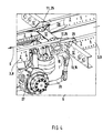
- FIG. 4 shows a section of the chassis frame 4 of a commercial vehicle 5, with respect to the vehicle longitudinal direction 6, a front module 3; 8 and a center module 3; 9, both of which are at the same height level with respect to the vehicle longitudinal direction 6.
- the two side members 2 are connected to each other via the cross member 12.
- a connection shoe 1 is provided, at the connecting flanges 10; 28; 29 on the outside of the longitudinal member 2 of the chassis frame 4, a cross member 12 is arranged.
- connection shoe 1 Seen in the vehicle longitudinal direction 6, on the underside of the connecting shoe 1 is formed as a bearing 13 connecting element 15, on which a stabilizer 26 is arranged.
- the stabilizer 26 connects a vehicle axle 27 with the connection shoe 1, whereby an indirect connection of the vehicle axle 27 on the chassis frame 4 is effected.
- the connection shoe 1 is used via the bearing 13 for fastening the stabilizer 26 to the chassis frame 4 of the commercial vehicle 5.
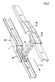
- FIGS. 5 to 9 show each two, in the vehicle longitudinal direction 6 parallel to each other arranged connection shoes 1 with the inside arranged side rails 2.
- the hole patterns 11 of the connecting flanges 10 are identical to the hole patterns 11 of the connecting flanges 28 of the connection shoes 1, so that in the vehicle longitudinal direction 6 opposite each other and each end face in pairs abutting longitudinal members 2 are connected via identical connection shoes 1 with each other.
- the connecting flanges 10; 28 of the connection shoe 1 extend relative to the vehicle longitudinal direction 6 to each other horizontally offset.
- the side members 2 are connected approximately at right angles to a rear cross member 12 which is relative to the vehicle longitudinal direction 6.
- the Fig. 7 corresponds to the representation of Fig. 6 with the difference that in Fig. 7 a relative to the vehicle longitudinal direction 6 front cross member 12 is shown.
- Fig. 8 For connecting the side members 2, two cross members 12 are shown in each case Fig. 9 are connected via a running in the vehicle longitudinal direction 6 connection 31 with each other.
Landscapes
- Engineering & Computer Science (AREA)
- Chemical & Material Sciences (AREA)
- Combustion & Propulsion (AREA)
- Transportation (AREA)
- Mechanical Engineering (AREA)
- Body Structure For Vehicles (AREA)
- Automatic Cycles, And Cycles In General (AREA)
Abstract
Description
- Die Erfindung betrifft ein Nutzfahrzeug mit einem Fahrgestellrahmen, der durch Querträger verbundene Längsträger umfasst, die jeweils durch je einen Verbindungsschuh miteinander verbunden sind, wobei der Fahrgestellrahmen aus einzelnen Modulen zusammengesetzt ist.
- Der Fahrgestellrahmen bildet die Basis für das Fahrgestell eines Nutzfahrzeugs. Er nimmt alle Achsen und den gesamten Antriebsstrang mit dem Motor und dem Getriebe auf. Zusätzlich trägt er das Fahrerhaus sowie die vorhandenen Aufbauten. Der Fahrgestellrahmen eines Nutzfahrzeugs umfasst in der Regel zwei Längsträger, die durch mehrere parallel zueinander verlaufende Querträger verbunden sind. Da eine Zugmaschine mit einem auf dem Fahrgestellrahmen montierten Fahrerhaus mit verschiedenen Aufbauten kombiniert werden kann, ist es heute im LKW- und Busbau üblich, den Fahrzeugrahmen in ein Front-, ein Mittel- und ein Heckmodul zu unterteilen. Je nachdem, für welchen Einsatzzweck das jeweilige Nutzfahrzeug gedacht ist, sind jeweils vorgefertigte Front- und Heckmodule miteinander kombinierbar. Zur Verbindung des Front- mit dem Heckmodul kann zwischen beiden Modulen wenigstens ein Mittelmodul angeordnet werden. Die jeweiligen Module werden im Bereich der Längsträger durch Verbindungsschuhe aneinander befestigt. Wegen der hohen Achslasten des Front- und des Heckmoduls haben sich bei den heutigen Nutzfahrzeugen Starrachsen durchgesetzt. Zu den wichtigsten Bauteilen der Radaufhängung solcher Achsen zählen dabei die so genannten Achslenker. Sie verbinden die Rad- bzw. Achsführung mit dem Fahrgestellrahmen und nehmen so die Rad- bzw. Achsführungskräfte auf. Vorstellbar sind hierbei zum Beispiel Quer- und Dreieckslenker. Längslenker werden hingegen in Kombination mit der Luftfederung eingesetzt, wobei der Längslenker in der Regel nur Kräfte in Längsrichtung übernimmt. Sowohl bei der Verbindung der jeweils aneinander anstoßenden Längsträger der Front-, Mittel- und Heckmodule als auch bei der Anbindung der Achslenker an den Rahmenlängsträger kommen Multifunktionslagerböcke zum Einsatz.
- Aus der
EP 1 110 848 B 1 ist ein Längslenkerbock bekannt, der an einem Rahmenlängsträger eines Nutzfahrzeugs angeordnet ist und Mittel zur Abstützung und Lagerung von Längslenkern sowie wenigstens einen Stabilisator aufweist. Der Längslenkerbock weist Mittel zur Abstützung und Lagerung von Dreieckslenkern und wenigstens eine Ausmuldung zur bereichsweise umgreifenden Aufnahme des endseitigen Bereiches des Torosionsabschnittes auf. Der Torosionsabschnitt gehört dabei wenigstens einem, quer zur Ausmuldung verlaufenden Stabilisator. Zur Befestigung des jeweiligen Stabilisators am Längslenkerbock wirkt die Ausmuldung mit einer, den Stabilisator bereichsweise umgreifenden Haltemuffe zusammen. - Aus der
DE 93 08 329 geht weiterhin ein Rahmen eines Nutzfahrzeugs, insbesondere eines Frontlenker-Lastkraftwagens hervor, der zwei über Querträger verbundene Längsträger aufweist. Der Rahmen setzt sich aus mehreren vorgefertigten bzw. vormontierten Modulen zusammen, von denen jeder aus zwei, durch wenigstens einen Querträger verbundenen Längsabschnitten besteht. Die Längsträgerabschnitte zweier an aneinander angrenzender Rahmenmodule sind bei der Rahmen-Endmontage zueinander fluchtend angeordnet und werden über einen, als Längs- und Quer-Verbindungsorgan dienenden Querträger miteinander verbunden. Hierbei überbrückt der Querträger mit seinen Anschlussorganen, die an beiden Enden vorgesehen sind, die jeweilige Stoßfuge zwischen zwei Modulen. - Nachteilig ist jedoch, dass bei heutigen Fahrgestellrahmen die elektrischen Leitungen, die Druckluftleitung sowie sonstige Leitungen, die der Wasser- oder der Betriebsstoffversorgung dienen oftmals an der Unterseite des Fahrgestellrahmens eines LKWs oder eines Busses angeordnet sind. Die Leitungen sind im Regelfall der Beschädigung durch aufgewirbelte Steine oder durch Spritzwasser schutzlos ausgeliefert.
- Es ist daher die Aufgabe der vorliegenden Erfindung einen Fahrgestellrahmen für ein Nutzfahrzeug zu schaffen, bei dem wichtige elektrische oder pneumatische Leitungen sowie Versorgungsleitungen zum Transport von Wasser oder Betriebsstoff vor Beschädigung geschützt sind.
- Die Aufgabe wird durch die Merkmale des Patentanspruchs 1 gelöst.
Das erfindungsgemäße Nutzfahrzeug umfasst einen Fahrgestellrahmen, dessen Längsträger durch eine Vielzahl von Querträgern mit einander verbunden sind und der aus einzelnen Modulen zusammengesetzt ist. Die einzelnen Module können sich relativ zur Fahrzeuglängsrichtung auf einem einheitlichen oder aber auf unterschiedlichen Höhenniveaus befinden. Die jeweiligen längs aneinander anstoßenden einzelnen Module des Fahrgestellrahmens sind durch Verbindungsschuhe miteinander verbunden. Je nachdem, ob sich die aneinander anstoßenden Längsträgermodule in Bezug zur Fahrzeuglängsrichtung auf einem einheitlichen oder auf unterschiedlichen Höhenniveaus befinden, erstreckt sich der jeweilige Verbindungsschuh achsparallel zur Fahrzeuglängsachse. Befinden sich die aneinander angrenzenden Längsträgermodule auf unterschiedlichen Höhenniveaus und/oder sind die stirnseitig aneinander anstoßenden Längsträger in Fahrzeuglängsrichtung zueinander horizontal seitlich versetzt, so weisen die Verbindungsschuhe zum Ausgleich des Höhenniveaus in Längsrichtung gesehen einen Knick auf. Das Frontmodul befindet sich im Bereich eines herkömmlichen Nutzfahrzeugs im Bereich des Fahrerarbeitsplatzes und umfasst den Motor, das Getriebe sowie wenigstens eine Achse. Das Heckmodul umfasst die wenigstens eine rückwärtige Achse des Busses oder des LKWs. Das Front- und das Heckmodul werden jeweils durch wenigstens ein Mittelmodul miteinander verbunden, wobei insbesondere bei Bussen, die im Nahverkehr eingesetzt werden, das wenigstens eine Mittelmodul oftmals relativ zum Front- und Heckmodul tiefer gelegt ist. Die Verbindungsschuhe können je nach Größe und Schwere des Nutzfahrzeugs als Guss- oder Schmiedeteile gefertigt sein. Abhängig vom jeweiligen Verwendungszweck überbrückt der Verbindungsschuh auf engstem Raum einen horizontalen und/oder vertikalen Rahmenversatz zwischen den Längsträgermodulen. Quer zur Fahrzeuglängsrichtung sind an der Außenseite des Verbindungsschuhs an diesem oder am Längsträger weitere Querträger angeordnet, die z.B. der Abstützung der Karosserie des Fahrzeuges dienen. Der weitere Querträger kann als C-Profil oder in Rohrform gefertigt sein. Der Querträger ist dabei in etwa rechtwinklig zur Fahrzeuglängsachse an der Außenseite des Verbindungsschuhs befestigt und kann mit dem Längsträger bzw. mit dem Verbindungsschuh verschraubt, vernietet oder mit den genannten Bauteilen einstückig gefertigt sein. Ist eine weitere Versteifung der Karosserie erforderlich, können an der Außenseite eines Verbindungsschuhs jeweils zwei weitere Querträger angeordnet sein. Die Längsträger, die Querträger und die weiteren Querträger sind jeweils als C-Profil ausgebildet. Denkbar sind jedoch auch alle anderen im Fahrzeugbau verwendeten Profilformen. Rohrleitungen für Fluide, elektrische Leitungen oder Rohrleitungen für die Druckluftversorgung verlaufen im Nutzfahrzeug entlang der Längs- und der Querträger. Zur Verbindung einzelner Leitungselemente mit einander sind Ausdehnungsstücke, Dichtungen, Flansche und Muffen vorgesehen. Bei der Konstruktion des Fahrzeugs müssen für die Verlegung der Versorgungsleitungen die Trennstellen der einzelnen Module besonders beachtet werden. Aus Fertigungs- und Montagezwecken müssen die Trennstellen der Versorgungsleitungen mit den Trennstellen der Module übereinstimmen. Die Versorgungsleitungen sind dabei verliersicher an den Längs- und Querträgern des Fahrgestellrahmens zu befestigen.
Erfindungsgemäß ist es vorgesehen, die Versorgungsleitungen in die Verbindungsschuhe zu integrieren. Transportleitungen sowie die Schächte für Transportleitungen können bei gegossenen Verbindungsschuhen in beliebiger Anzahl im Verbindungsschuh vorgesehen sein. Der Vorteil der Erfindung besteht somit darin, dass der Verbindungsschuh nicht nur die Trennstelle zwischen den einzelnen Modulen des Fahrgestellrahmens bildet, sondern auch die Schnittstelle für die Betriebsstoff-, Hydraulik- und Pneumatikversorgungsleitungen bildet. Der erfindungsgemäße Verbindungsschuh weist zur Verbindung mit anderen Bauteilen ein genormtes Lochbild auf. Das Lochbild kann an den einzelnen Flanschflächen z.B. symmetrisch oder asymmetrisch gestaltet sein, so dass ein anzuschließendes Bauteile um seine Längsachse gedreht einbaubar ist. Der Vorteil besteht darin, dass auf diese Weise auch einen Versatz des Bauteils in entgegen gesetzter Richtung realisierbar ist. - Eine weitere Ausführungsform der Erfindung sieht vor, dass das Verbindungselement an den Verbindungsschuh angeformt ist. Der Verbindungsschuh kann dabei kraft-, form- und stoffschlüssig mit dem Verbindungselement verbunden sein. Durch den Wegfall zusätzlicher Verbindungselemente können die Herstellungskosten des Fahrzeugs gesenkt werden.
- In einer anderen Ausführungsform der Erfindung ist vorgesehen, dass das Verbindungselement ein in den Verbindungsschuh integriertes Rohrstück ist. An jedem Ende des Rohrstücks ist je eine Kupplung vorgesehen, die einen Anschluss an eine, am Fahrgestellrahmen geführte Leitung ermöglicht. Im Verbindungsschuh können mehrere Rohrstücke unterschiedlichen Durchmessers vorgesehen sein. Die Rohrstücke können zur Durchführung von elektrischen Leitungen isoliert sein oder isolierende Kunststoffinlays aufweisen. Die Kupplungen sind genormt und ermöglichen so eine gegenseitige Verbindung der Leitungen am Fahrgestellrahmen.
- Eine weitere Ausführungsform der Erfindung sieht vor, dass das Verbindungselement ein in den Verbindungsschuh integriertes elektrisches Leiterelement ist, das an eine am Fahrgestellrahmen geführte elektrische Leitung anschließbar ist. Auf diese Weise sind die Kabelstränge gegenüber dem metallischen Fahrgestellrahmen des Nutzfahrzeugs isoliert und zusätzlich vor äußerer Beschädigung oder Wassereinbruch geschützt.
Weiterhin ist vorgesehen, dass das Verbindungselement eine am Verbindungsschuh angeordnete Halterung ist, die zur Befestigung einer Vielzahl von Leitungen dient und dabei den Verbindungsbereich zwischen zwei aneinander anstoßenden Modulen überbrückt. Hierbei kann die Halterung als Klemmbuchse ausgebildet sein. Das Verbindungselement umfasst jeweils mindestens zwei miteinander kommunizierende Steckelemente, von denen das eine am Verbindungsschuh angeordnet ist und das andere an der Verbindungsleitung befestigt ist. Die Montage bzw. die Demontage des Verbindungsschuhs am/vom Längs- oder Querträger zu Reparatur- oder Wartungszwecken wird auf diese Weise wesentlich erleichtert. - Eine zusätzliche Ausführungsform der Erfindung sieht vor, dass das Verbindungselement die Form einer Buchse aufweist, in die ein rohrförmiges Anschlussstück eines am Fahrgestellrahmen zu befestigenden Bauteils einsteckbar ist. Auf diese Weise lässt sich der Stabilisator in einer spannungsoptimierten Position am Fahrgestellrahmen anordnen, in der ein direkter Kraftfluss in das Bauteil gewährleistet ist. Zur Reduzierung des Gewichts des Verbindungsschuhs sowie zur Reduzierung der Anzahl der zur Herstellung des Nutzfahrzeugs erforderlichen Einzelteile ist der Verbindungsschuh mit wenigstens einem Aufnahmeflansch für ein Stabilisatorlager ausgestattet.
- Weitere Merkmale, Einzelheiten und Vorteile der Erfindung ergeben sich aus der folgenden Beschreibung verschiedener Ausführungsformen der Erfindung sowie anhand der Zeichnung. Hierbei zeigen:
- Figur 1
- einen Verbindungsschuh, der zur Verbindung zweier Längsträger und zur Anbindung eines Querträger mit Verbindungsflanschen ausgerüstet ist,
- Figur 2
- einen Verbindungsschuh, vergleichbar mit
Figur 1 mit einem, in den Verbindungsschuh integrierten Verbindungselement, - Figur 3
- einen Verbindungsschuh entsprechend
Figur 1 mit Verbindungselementen, die auf der Oberseite des Verbindungsschuhs angeordnet sind, - Figur 4
- einen Fahrgestellrahmen eines Nutzfahrzeugs mit erfindungsgemäßen Verbindungsschuhen,
- Figur 5
- zwei parallel zu einander angeordnete Verbindungsschuhe mit innenseitig angeordneten Längsträgern,
- Figur 6
- zwei parallel zu einander angeordnete Verbindungsschuhe mit innenseitig angeordneten Längsträgern und einem heckseitigen Querträger,
- Figur 7
- zwei parallel zu einander angeordnete Verbindungsschuhe mit innenseitig angeordneten Längsträgern und einem frontseitigen Querträger,
- Figur 8
- zwei parallel zu einander angeordnete Verbindungsschuhe mit innenseitig angeordneten Längsträgern und zwei Querträgern und
- Figur 9
- zwei parallel zu einander angeordnete Verbindungsschuhe mit innenseitig angeordneten Längsträgern und zwei mit einander verbundenen Querträgern.
- In den
Figuren 1 bis 3 verlaufen die Verbindungsflansche 10; 28; 29 des Verbindungsschuhs 1 relativ zur Fahrzeuglängsrichtung 6 vertikal und horizontal zueinander versetzt. InFig. 4 sind die Verbindungsflansche 10; 28; 29 relativ zur Fahrzeuglängsrichtung 6 horizontal zueinander versetzt angeordnet. In Fahrzeuglängsrichtung 6 weisen die Verbindungsflansche 10; 28 des Verbindungsschuhs 1 einheitliche Lochbilder 11 auf. Auf diese Weise ist der Verbindungsschuh 1 als Normteil um seine Längsachse drehbar und seine Befestigung relativ zur Fahrzeuglängsrichtung 6 auf beiden Seiten des Fahrgestellrahmens 4 an den Längsträgern 2 (nicht gezeigt) möglich. -
Figur 1 zeigt einen Verbindungsschuh 1, der je zwei Längsträger 2 eines Moduls 3 eines Fahrgestellrahmens 4 eines Nutzfahrzeugs 5 mit einander verbindet. Der Verbindungsschuh 1 weist in Fahrzeuglängsrichtung 6 einen Knick 7 auf, mit dem der Verbindungsschuh 1 den horizontalen Höhenunterschied des Frontmoduls 3; 8 gegenüber dem Mittelmodul 3; 9 sowie den vertikalen Versatz der stirnseitig aneinander anstoßenden Längsträger 2 ausgleicht. In Fahrzeuglängsrichtung 6 sowie quer zur Fahrzeuglängsrichtung 6 sind Verbindungsflansche 10; 28; 29 des Verbindungsschuhs 1 mit Lochbildern 11 ausgestattet, die eine Anbindung von Querträgern 12 und Längsträgern 2 an den Verbindungsschuh 1 ermöglichen. Relativ zur Fahrzeuglängsrichtung 6 ist in denFiguren 1 bis 3 an der Unterseite des Verbindungsschuhs 1 je ein als Verbindungselement 15 dienendes Lager 13 zur Anbindung eines nicht dargestellten Stabilisators 26 angeordnet. Das Verbindungselement 15 ist in Form einer Öse ausgebildet und sitzt in Fahrzeuglängsrichtung 6 gesehen unter, vor oder hinter einem Verbindungsflansch 29. Die Öse ist zusätzlich quer Fahrzeuglängsrichtung 6 unter dem Verbindungsflansch 29 oder unter einer Seitenwand 30 des Verbindungsschuhs 1 positionierbar. Zur Gewichtsreduzierung weist der Verbindungsschuh 1 Durchbrüche 14 auf. -
Figur 2 zeigt einen Verbindungsschuh 1 entsprechend der Darstellung inFigur 1 . An dem Verbindungsschuh 1 sind Verbindungselemente 15 erkennbar, die dem Anschluss von Leitungen 16 dienen, die am Fahrgestellrahmen 4 geführt sind. Das inFigur 2 dargestellte Verbindungselement 15 ist ein, in den Verbindungsschuh 1 integriertes Rohrstück 17, welches an seinen Enden je eine Kupplung 18 aufweist. Die Kupplungen 18 verbinden das Rohrstück 17 mit den Leitungen 16, die am Fahrgestellrahmen 4 entlang geführt sind. Das Rohrstück 17 kann ein in den Verbindungsschuh 1 integriertes elektrisches Leiterelement aufnehmen, das an eine, am Fahrgestellrahmen 4 angeordnete elektrische Leitung anschließbar ist. Der inFigur 2 dargestellte Verbindungsschuh 1 weist Verbindungsflansche 10; 28 auf, an denen die Längsträger 2 befestigbar sind. Zusätzlich ist in Fahrzeuglängsrichtung 6 auf der Unterseite des Verbindungsschuhs 1 das Lager 13 zur Befestigung des Stabilisators 26 (nicht gezeigt) dargestellt. Die beiden an einander angrenzenden Module 3; 8; 9 verlaufen in Fahrzeuglängsrichtung 6 gesehen auf unterschiedlicher Höhe. Das Rohrstück 17 ist inFigur 2 in den Verbindungsschuh 1 integriert. Das Rohrstück 17 kann am Verbindungsschuh 1 angeformt sein, oder in jeder anderen Weise kraft-, stoff- oder formschlüssig mit dem Verbindungsschuh 1 verbunden sein. Zur Befestigung des Rohrstücks 17 im Verbindungsschuh 1 sind Muttern 19 angeordnet, die das Rohrstück 17 als Verbindungselement 15 verliersicher im Verbindungsschuh 1 halten. Das Rohrstück 17 weist zu beiden Enden Anschlussflansche auf, mit denen in- bzw. entgegen der Fahrzeuglängsrichtung 6 Leitungen 16 anschließbar sind. Werden im Inneren des Rohrstücks 17 elektrische Leiterelemente geführt, sind an den beiden Enden des Rohrstückes 17 Steckbuchsen vorgesehen, die eine elektrische Verbindung zu den elektrischen Leitungen aufrechterhalten. -
Figur 3 zeigt einen erfindungsgemäßen Verbindungsschuh 1, der in Fahrzeuglängsrichtung 6 einen Knick 7 aufweist, mit dem der Höhenunterschied zwischen je zwei Modulen 3; 8; 9 des Fahrgestellrahmens 4 des Nutzfahrzeugs 5 sowie der vertikale Versatz der stirnseitig aneinander anstoßenden Längsträger 2 ausgleichbar ist. Der Verbindungsschuh 1 weist in Fahrzeuglängsrichtung 6 Verbindungsflansche 10; 28; 29 auf, über deren Lochbilder 11 weitere Bauteile des Nutzfahrzeugs 5 am Fahrgestellrahmen 4 befestigbar sind. Der Querträger 12 verbindet die einander gegenüberliegenden Verbindungsschuhe 1 mit einander und greift dabei am Verbindungsflansch 29 des jeweiligen Verbindungsschuhs 1 an. Mittelbar verbindet der Querträger 12 über die Verbindungsschuhe 1 quer zur Fahrzeuglängsrichtung 6 auch die an den Verbindungsflanschen 10; 28 der jeweiligen Verbindungsschuhe 1 angebrachten Längsträger 2 mit einander. Unterhalb des Verbindungsflansches 10; 28; 29 des Verbindungsschuhs 1 ist ein Lager 13 vorgesehen, an dem zur Stabilisierung der Fahrzeugachse 27 ein Stabilisator 26 und ein Längslenker oder ein anderes Bauelement befestigbar sind. In Fahrzeuglängsrichtung 6 an der Oberseite des Verbindungsschuhs 1 sind zur Befestigung von Halterungen 20 vorgesehen. Die Leitungen 16 überbrücken dabei die aneinander anstoßenden Stirnseiten der Längsträger 2 der Module 3, 8; 9. Die Halterungen 20 können kraftschlüssig, stoffschlüssig oder formschlüssig mit dem Verbindungsschuh 1 verbunden sein. In Fahrzeuglängsrichtung 6 gesehen sind die Halterungen 20 an der Oberseite, an der Unterseite oder seitlich am Verbindungsschuh 1 angebracht. Denkbar ist auch, die Halterungen 20 in Fahrzeuglängsrichtung 6 gesehen an der Innenseite der jeweiligen Oberseite, der Unterseite oder der Seitenfläche des Verbindungsschuhs 1 anzuordnen. Die Leitungen 16 können an den Halterungen 20 festgeklippst sein. Denkbar ist darüber hinaus, dass die Halterungen 20 als Ösen ausgebildet sind, die die Leitungen 16 durchsetzen. Die Leitungen 16 sind darüber hinaus in jeder technisch realisierbaren Weise z.B. mit Hilfe von Klemmbuchsen an den Halterungen 20 befestigbar. Die Halterungen 20 umfassen Verbindungseinrichtungen in Form von Steckvorrichtungen oder Gewinden 24, mit deren Hilfe die Leitungen 16 verliersicher eingesteckt oder verschraubt werden können. Die vorausgehende Aufzählung ist dabei in keiner Weise abschließend gemeint. Die Halterung 20 ist ein technisches Verbindungselement 15, das zwei Leitungsstücke 16 verliersicher und dichtend miteinander verbindet. Die Halterung 20 umfasst einen Fuß 21, an dem mindestens eine Halteeinrichtung 22 angeordnet ist. Zusätzlich kann die Halterung 20 auch als Bohrung 23 eines Lochbildes 11 ausgebildet sein. Zur Verbindung zweier Leitungen 16 kann in der Bohrung 23 eine als Gewinde 24 oder als Rastvorrichtung 24 ausgebildete Kupplung 18 vorgesehen sein. Die Aufzählung ist in keiner Weise abschließend gemeint, vielmehr können auch andere technische Verbindungseinrichtungen zur Anwendung kommen. -
Figur 4 zeigt einen Ausschnitt des Fahrgestellrahmens 4 eines Nutzfahrzeugs 5, der in Bezug zur Fahrzeuglängsrichtung 6 ein Frontmodul 3; 8 und ein Mittelmodul 3; 9 umfasst, welche beide in Bezug zur Fahrzeuglängsrichtung 6 auf dem gleichen Höhenniveau liegen. Innerhalb eines Moduls 3 sind die beiden Längsträger 2 über den Querträger 12 miteinander verbunden. Zur Verbindung zweier Längsträger 2 in Fahrzeuglängsrichtung 6 ist ein Verbindungsschuh 1 vorgesehen, an dessen Verbindungsflanschen 10; 28; 29 an der Außenseite des Längsträgers 2 des Fahrgestellrahmens 4 ein Querträger 12 angeordnet ist. Zur Befestigung der Längsträger 2 aneinander sowie zur Befestigung der Querträger 12 am Verbindungsschuh 1 sind am Verbindungsschuh 1 Lochbilder 11 angebracht, die den Durchtritt von Verbindungsschrauben 25 ermöglichen. In Fahrzeuglängsrichtung 6 gesehen, an der Unterseite des Verbindungsschuhs 1 ist das als Lager 13 ausgebildete Verbindungselement 15 darstellt, an dem ein Stabilisator 26 angeordnet ist. Der Stabilisator 26 verbindet eine Fahrzeugachse 27 mit dem Verbindungsschuh 1, wodurch eine mittelbare Anbindung der Fahrzeugachse 27 am Fahrgestellrahmen 4 bewirkt wird. Erfindungsgemäß dient der Verbindungsschuh 1 über das Lager 13 der Befestigung des Stabilisators 26 am Fahrgestellrahmen 4 des Nutzfahrzeugs 5. - Die
Figuren 5 bis 9 zeigen jeweils zwei, in Fahrzeuglängsrichtung 6 parallel zu einander angeordnete Verbindungsschuhe 1 mit innenseitig angeordneten Längsträgern 2. Die Lochbilder 11 der Verbindungsflansche 10 sind mit den Lochbildern 11 der Verbindungsflansche 28 der Verbindungsschuhe 1 identisch, sodass die in Fahrzeuglängsrichtung 6 einander gegenüber liegenden und jeweils stirnseitig paarweise aneinander anstoßenden Längsträger 2 über identische Verbindungsschuhe 1 mit einander verbindbar sind. Die Verbindungsflansche 10; 28 des Verbindungsschuhs 1 verlaufen relativ zur Fahrzeuglängsrichtung 6 zueinander horizontal versetzt. InFig. 6 sind die Längsträger 2 in etwa rechtwinklig mit einem relativ zur Fahrzeuglängsrichtung 6 hinteren Querträger 12 verbunden. DieFig. 7 entspricht der Darstellung derFig. 6 mit dem Unterschied, dass inFig. 7 ein relativ zur Fahrzeuglängsrichtung 6 vorderer Querträger 12 dargestellt ist. InFig. 8 sind zur Verbindung der Längsträger 2 jeweils zwei Querträger 12 gezeigt, die inFig. 9 über eine in Fahrzeuglängsrichtung 6 verlaufende Verbindung 31 mit einander verbunden sind. -
- 1) Verbindungsschuh
- 2) Längsträger
- 3) Modul
- 4) Fahrgestellrahmen
- 5) Nutzfahrzeug
- 6) Fahrzeuglängsrichtung
- 7) Knick
- 8) Frontmodul
- 9) Mittelmodul
- 10) Verbindungsflansch
- 11) Lochbild
- 12) Querträger
- 13) Lager
- 14) Durchbruch
- 15) Verbindungselement
- 16) Leitung
- 17) Rohrstück
- 18) Kupplung
- 19) Mutter
- 20) Halterungen
- 21) Fuß
- 22) Halteeinrichtung
- 23) Bohrung
- 24) Gewinde
- 25) Verbindungsschraube
- 26) Stabilisator
- 27) Fahrzeugachse
- 28) Verbindungsflansch
- 29) Verbindungsflansch
- 30) Seitenwand
- 31) Verbindung
Claims (9)
- Nutzfahrzeug mit einem Fahrgestellrahmen (4), der durch Querträger (12) verbundene Längsträger (2) umfasst, die durch je einen Verbindungsschuh (1) mit einander verbunden sind, wobei der Fahrgestellrahmen (4) aus Einzelmodulen (3; 8; 9) zusammengesetzt ist, dadurch gekennzeichnet, dass der Verbindungsschuh (1) Verbindungselemente (15) zum Anschluss von, an dem Fahrgestellrahmen (4) geführten Leitungen (16) und mit dem Fahrgestellrahmen (4) verbundenen Bauteilen aufweist.
- Nutzfahrzeug nach Anspruch 1, dadurch gekennzeichnet, dass das Verbindungselement (15) an den Verbindungsschuh (1) angeformt ist.
- Nutzfahrzeug nach Anspruch 1, dadurch gekennzeichnet, dass das Verbindungselement (15) ein in den Verbindungsschuh (1) integriertes Rohrstück (17) ist.
- Nutzfahrzeug nach Anspruch 3, dadurch gekennzeichnet, dass das Rohrstück (17) an seinen beiden Enden je eine Kupplung (18) aufweist, die einen Anschluss an eine am Fahrgestellrahmen (4) geführte Leitung (16) ermöglichen.
- Nutzfahrzeug nach Anspruch 1, dadurch gekennzeichnet, dass das Verbindungselement (15) ein in den Verbindungsschuh (1) integriertes elektrisches Leiterelement (15) ist, das an eine am Fahrgestellrahmen (4) geführte elektrische Leitung anschließbar ist.
- Nutzfahrzeug nach Anspruch 1, dadurch gekennzeichnet, dass das Verbindungselement (15) eine am Verbindungsschuh (1) angeordnete Halterung (20) ist, die zur Befestigung eines über die Verbindung der Module (3; 8; 9) geführten Leitungssystems (i 6) vorgesehen ist.
- Nutzfahrzeug nach Anspruch 6, dadurch gekennzeichnet, dass die Halterung (20) eine Klemmbuchse ist.
- Nutzfahrzeug nach Anspruch 1, dadurch gekennzeichnet, dass das Verbindungselement (15) eine Buchse ist, in welches ein rohrförmiges Anschlussstück eines an dem Fahrgestellrahmen (4) zu befestigenden Bauteils einsteckbar ist.
- Nutzfahrzeug nach Anspruch 1, dadurch gekennzeichnet, dass der Verbindungsschuh (1) ein Lager (13) zur Befestigung eines Stabilisators (13) aufweist.
Applications Claiming Priority (1)
| Application Number | Priority Date | Filing Date | Title |
|---|---|---|---|
| DE201110122460 DE102011122460A1 (de) | 2011-12-22 | 2011-12-22 | Nutzfahrzeug mit einem modularen Fahrgestellrahmen, dessen Längsträger durch Querträger verbunden sind |
Publications (3)
| Publication Number | Publication Date |
|---|---|
| EP2607211A2 true EP2607211A2 (de) | 2013-06-26 |
| EP2607211A3 EP2607211A3 (de) | 2014-09-24 |
| EP2607211B1 EP2607211B1 (de) | 2017-02-01 |
Family
ID=46799184
Family Applications (1)
| Application Number | Title | Priority Date | Filing Date |
|---|---|---|---|
| EP12400036.5A Active EP2607211B1 (de) | 2011-12-22 | 2012-08-23 | Nutzfahrzeug mit einem modularen Fahrgestellrahmen, dessen Längsträger durch Querträger verbunden sind |
Country Status (2)
| Country | Link |
|---|---|
| EP (1) | EP2607211B1 (de) |
| DE (1) | DE102011122460A1 (de) |
Cited By (2)
| Publication number | Priority date | Publication date | Assignee | Title |
|---|---|---|---|---|
| AT516923A3 (de) * | 2015-03-03 | 2018-01-15 | Siemens Ag Oesterreich | Längsträger und Querträger für einen Fahrwerksrahmen eines Schienenfahrzeuges |
| CN113879396A (zh) * | 2021-10-22 | 2022-01-04 | 一汽解放汽车有限公司 | 底盘结构及电动汽车 |
Citations (2)
| Publication number | Priority date | Publication date | Assignee | Title |
|---|---|---|---|---|
| DE9308329U1 (de) | 1993-06-03 | 1993-07-22 | MAN Nutzfahrzeuge AG, 80995 München | Rahmen eines Nutzfahrzeuges |
| EP1110848B1 (de) | 1999-12-21 | 2004-09-01 | MAN Nutzfahrzeuge Aktiengesellschaft | Längslenkerbock in Nutzfahrzeugen |
Family Cites Families (3)
| Publication number | Priority date | Publication date | Assignee | Title |
|---|---|---|---|---|
| US7270346B2 (en) * | 2004-09-27 | 2007-09-18 | Oshkosh Truck Corporation | Vehicle frame |
| DE102008045008A1 (de) * | 2008-08-29 | 2010-03-04 | Man Nutzfahrzeuge Aktiengesellschaft | Modularer Multifunktionslagerbock |
| DE102008056406A1 (de) * | 2008-11-07 | 2010-05-12 | Man Nutzfahrzeuge Ag | Fahrgestellrahmen mit variabler Schnittstelle |
-
2011
- 2011-12-22 DE DE201110122460 patent/DE102011122460A1/de not_active Withdrawn
-
2012
- 2012-08-23 EP EP12400036.5A patent/EP2607211B1/de active Active
Patent Citations (2)
| Publication number | Priority date | Publication date | Assignee | Title |
|---|---|---|---|---|
| DE9308329U1 (de) | 1993-06-03 | 1993-07-22 | MAN Nutzfahrzeuge AG, 80995 München | Rahmen eines Nutzfahrzeuges |
| EP1110848B1 (de) | 1999-12-21 | 2004-09-01 | MAN Nutzfahrzeuge Aktiengesellschaft | Längslenkerbock in Nutzfahrzeugen |
Cited By (3)
| Publication number | Priority date | Publication date | Assignee | Title |
|---|---|---|---|---|
| AT516923A3 (de) * | 2015-03-03 | 2018-01-15 | Siemens Ag Oesterreich | Längsträger und Querträger für einen Fahrwerksrahmen eines Schienenfahrzeuges |
| US10766509B2 (en) | 2015-03-03 | 2020-09-08 | Siemens Mobility Austria Gmbh | Longitudinal support and transverse support for a chassis frame of a rail vehicle |
| CN113879396A (zh) * | 2021-10-22 | 2022-01-04 | 一汽解放汽车有限公司 | 底盘结构及电动汽车 |
Also Published As
| Publication number | Publication date |
|---|---|
| EP2607211A3 (de) | 2014-09-24 |
| EP2607211B1 (de) | 2017-02-01 |
| DE102011122460A1 (de) | 2013-06-27 |
Similar Documents
| Publication | Publication Date | Title |
|---|---|---|
| DE102010014302B4 (de) | Luftfahrzeug und Befestigungsanordnung für eine Fußbodenstruktur in einem Luftfahrzeug | |
| DE102018101362B4 (de) | Elektrofahrzeug | |
| DE102008039949B4 (de) | Querträger für ein Nutzfahrzeug | |
| DE102008014501B4 (de) | Kraftfahrzeug mit einem seitliche Längsträger umfassenden Fahrzeugaufbau | |
| EP2822831B1 (de) | Strukturstabile anordnung und verfahren zur bildung einer strukturstabilen anordnung | |
| EP2159135B1 (de) | Nutzfahrzeugrahmen mit modularem Multifunktionslagerblock | |
| EP4237267B1 (de) | Fahrzeug mit batteriehalterung | |
| WO2022101180A1 (de) | Baukastensystem für eine energiespeicher–bodengruppe für einen elektrisch antreibbaren personenkraftwagen sowie verfahren zum herstellen einer derartigen energiespeicher-bodengruppe | |
| WO2022049170A1 (de) | Energiespeicher-bodengruppe für einen elektrisch antreibbaren personenkraftwagen | |
| EP2663463B1 (de) | Lagerung eines achsgetriebes im heckbereich eines personenkraftwagens | |
| DE102019106226A1 (de) | Kraftfahrzeug mit einem Achsträger und einer elektrischen Speichereinheit | |
| EP2607211B1 (de) | Nutzfahrzeug mit einem modularen Fahrgestellrahmen, dessen Längsträger durch Querträger verbunden sind | |
| DE102016109184B4 (de) | Haltebock | |
| DE102019203104B4 (de) | Rahmeneinrichtung für ein Fahrzeug, insbesondere für ein Kraftfahrzeug, sowie Fahrzeug mit wenigstens einer solchen Rahmeneinrichtung | |
| DE3151280C2 (de) | Fahrgestellrahmen für Fahrzeuge, insbesondere Omnibusse | |
| AT517794B1 (de) | Befestigungseinrichtung für einen Geräteträger an einem Wagenkasten eines Schienenfahrzeugs | |
| EP1710149B2 (de) | Schlussquerträger für ein Nutzfahrzeug | |
| DE102013211468B4 (de) | Längslenker | |
| EP1767426B1 (de) | Doppelstock-Schienenfahrzeug mit zumindest einer von einem Ende zum anderen Ende erstreckenden Leitung | |
| DE202016001857U1 (de) | Fahrmischer | |
| DE102016209614A1 (de) | Achsträger eines Kraftfahrzeuges | |
| DE602005003862T2 (de) | Karosserierahmen für Niederflurbus sowie Verfahren zu dessen Herstellung | |
| DE102006060405B3 (de) | Rahmenanordnung für ein Fahrzeug | |
| EP1931549A1 (de) | Untergestell für eisenbahnfahrzeuge | |
| DE102015100163B4 (de) | Personenkraftwagen mit Strebeneinrichtung |
Legal Events
| Date | Code | Title | Description |
|---|---|---|---|
| AK | Designated contracting states |
Kind code of ref document: A2 Designated state(s): AL AT BE BG CH CY CZ DE DK EE ES FI FR GB GR HR HU IE IS IT LI LT LU LV MC MK MT NL NO PL PT RO RS SE SI SK SM TR |
|
| AX | Request for extension of the european patent |
Extension state: BA ME |
|
| PUAI | Public reference made under article 153(3) epc to a published international application that has entered the european phase |
Free format text: ORIGINAL CODE: 0009012 |
|
| PUAL | Search report despatched |
Free format text: ORIGINAL CODE: 0009013 |
|
| AK | Designated contracting states |
Kind code of ref document: A3 Designated state(s): AL AT BE BG CH CY CZ DE DK EE ES FI FR GB GR HR HU IE IS IT LI LT LU LV MC MK MT NL NO PL PT RO RS SE SI SK SM TR |
|
| AX | Request for extension of the european patent |
Extension state: BA ME |
|
| RIC1 | Information provided on ipc code assigned before grant |
Ipc: B62D 21/12 20060101ALI20140819BHEP Ipc: B62D 21/17 20060101ALI20140819BHEP Ipc: B62D 21/11 20060101AFI20140819BHEP |
|
| 17P | Request for examination filed |
Effective date: 20140827 |
|
| REG | Reference to a national code |
Ref country code: DE Ref legal event code: R079 Ref document number: 502012009430 Country of ref document: DE Free format text: PREVIOUS MAIN CLASS: B62D0021110000 Ipc: B62D0021020000 |
|
| GRAP | Despatch of communication of intention to grant a patent |
Free format text: ORIGINAL CODE: EPIDOSNIGR1 |
|
| RIC1 | Information provided on ipc code assigned before grant |
Ipc: B62D 21/12 20060101ALI20160914BHEP Ipc: B62D 21/02 20060101AFI20160914BHEP Ipc: B62D 21/17 20060101ALI20160914BHEP |
|
| INTG | Intention to grant announced |
Effective date: 20161011 |
|
| GRAS | Grant fee paid |
Free format text: ORIGINAL CODE: EPIDOSNIGR3 |
|
| STAA | Information on the status of an ep patent application or granted ep patent |
Free format text: STATUS: GRANT OF PATENT IS INTENDED |
|
| GRAA | (expected) grant |
Free format text: ORIGINAL CODE: 0009210 |
|
| STAA | Information on the status of an ep patent application or granted ep patent |
Free format text: STATUS: THE PATENT HAS BEEN GRANTED |
|
| AK | Designated contracting states |
Kind code of ref document: B1 Designated state(s): AL AT BE BG CH CY CZ DE DK EE ES FI FR GB GR HR HU IE IS IT LI LT LU LV MC MK MT NL NO PL PT RO RS SE SI SK SM TR |
|
| REG | Reference to a national code |
Ref country code: GB Ref legal event code: FG4D Free format text: NOT ENGLISH |
|
| REG | Reference to a national code |
Ref country code: AT Ref legal event code: REF Ref document number: 865290 Country of ref document: AT Kind code of ref document: T Effective date: 20170215 Ref country code: CH Ref legal event code: EP |
|
| REG | Reference to a national code |
Ref country code: IE Ref legal event code: FG4D Free format text: LANGUAGE OF EP DOCUMENT: GERMAN |
|
| REG | Reference to a national code |
Ref country code: NL Ref legal event code: FP |
|
| REG | Reference to a national code |
Ref country code: DE Ref legal event code: R096 Ref document number: 502012009430 Country of ref document: DE |
|
| REG | Reference to a national code |
Ref country code: SE Ref legal event code: TRGR |
|
| REG | Reference to a national code |
Ref country code: LT Ref legal event code: MG4D |
|
| PG25 | Lapsed in a contracting state [announced via postgrant information from national office to epo] |
Ref country code: GR Free format text: LAPSE BECAUSE OF FAILURE TO SUBMIT A TRANSLATION OF THE DESCRIPTION OR TO PAY THE FEE WITHIN THE PRESCRIBED TIME-LIMIT Effective date: 20170502 Ref country code: HR Free format text: LAPSE BECAUSE OF FAILURE TO SUBMIT A TRANSLATION OF THE DESCRIPTION OR TO PAY THE FEE WITHIN THE PRESCRIBED TIME-LIMIT Effective date: 20170201 Ref country code: NO Free format text: LAPSE BECAUSE OF FAILURE TO SUBMIT A TRANSLATION OF THE DESCRIPTION OR TO PAY THE FEE WITHIN THE PRESCRIBED TIME-LIMIT Effective date: 20170501 Ref country code: LT Free format text: LAPSE BECAUSE OF FAILURE TO SUBMIT A TRANSLATION OF THE DESCRIPTION OR TO PAY THE FEE WITHIN THE PRESCRIBED TIME-LIMIT Effective date: 20170201 Ref country code: IS Free format text: LAPSE BECAUSE OF FAILURE TO SUBMIT A TRANSLATION OF THE DESCRIPTION OR TO PAY THE FEE WITHIN THE PRESCRIBED TIME-LIMIT Effective date: 20170601 Ref country code: FI Free format text: LAPSE BECAUSE OF FAILURE TO SUBMIT A TRANSLATION OF THE DESCRIPTION OR TO PAY THE FEE WITHIN THE PRESCRIBED TIME-LIMIT Effective date: 20170201 |
|
| REG | Reference to a national code |
Ref country code: FR Ref legal event code: PLFP Year of fee payment: 6 |
|
| PG25 | Lapsed in a contracting state [announced via postgrant information from national office to epo] |
Ref country code: LV Free format text: LAPSE BECAUSE OF FAILURE TO SUBMIT A TRANSLATION OF THE DESCRIPTION OR TO PAY THE FEE WITHIN THE PRESCRIBED TIME-LIMIT Effective date: 20170201 Ref country code: ES Free format text: LAPSE BECAUSE OF FAILURE TO SUBMIT A TRANSLATION OF THE DESCRIPTION OR TO PAY THE FEE WITHIN THE PRESCRIBED TIME-LIMIT Effective date: 20170201 Ref country code: PT Free format text: LAPSE BECAUSE OF FAILURE TO SUBMIT A TRANSLATION OF THE DESCRIPTION OR TO PAY THE FEE WITHIN THE PRESCRIBED TIME-LIMIT Effective date: 20170601 Ref country code: PL Free format text: LAPSE BECAUSE OF FAILURE TO SUBMIT A TRANSLATION OF THE DESCRIPTION OR TO PAY THE FEE WITHIN THE PRESCRIBED TIME-LIMIT Effective date: 20170201 Ref country code: BG Free format text: LAPSE BECAUSE OF FAILURE TO SUBMIT A TRANSLATION OF THE DESCRIPTION OR TO PAY THE FEE WITHIN THE PRESCRIBED TIME-LIMIT Effective date: 20170501 Ref country code: RS Free format text: LAPSE BECAUSE OF FAILURE TO SUBMIT A TRANSLATION OF THE DESCRIPTION OR TO PAY THE FEE WITHIN THE PRESCRIBED TIME-LIMIT Effective date: 20170201 |
|
| PG25 | Lapsed in a contracting state [announced via postgrant information from national office to epo] |
Ref country code: CZ Free format text: LAPSE BECAUSE OF FAILURE TO SUBMIT A TRANSLATION OF THE DESCRIPTION OR TO PAY THE FEE WITHIN THE PRESCRIBED TIME-LIMIT Effective date: 20170201 Ref country code: IT Free format text: LAPSE BECAUSE OF FAILURE TO SUBMIT A TRANSLATION OF THE DESCRIPTION OR TO PAY THE FEE WITHIN THE PRESCRIBED TIME-LIMIT Effective date: 20170201 Ref country code: SK Free format text: LAPSE BECAUSE OF FAILURE TO SUBMIT A TRANSLATION OF THE DESCRIPTION OR TO PAY THE FEE WITHIN THE PRESCRIBED TIME-LIMIT Effective date: 20170201 Ref country code: EE Free format text: LAPSE BECAUSE OF FAILURE TO SUBMIT A TRANSLATION OF THE DESCRIPTION OR TO PAY THE FEE WITHIN THE PRESCRIBED TIME-LIMIT Effective date: 20170201 Ref country code: RO Free format text: LAPSE BECAUSE OF FAILURE TO SUBMIT A TRANSLATION OF THE DESCRIPTION OR TO PAY THE FEE WITHIN THE PRESCRIBED TIME-LIMIT Effective date: 20170201 |
|
| REG | Reference to a national code |
Ref country code: DE Ref legal event code: R097 Ref document number: 502012009430 Country of ref document: DE |
|
| PG25 | Lapsed in a contracting state [announced via postgrant information from national office to epo] |
Ref country code: SM Free format text: LAPSE BECAUSE OF FAILURE TO SUBMIT A TRANSLATION OF THE DESCRIPTION OR TO PAY THE FEE WITHIN THE PRESCRIBED TIME-LIMIT Effective date: 20170201 Ref country code: DK Free format text: LAPSE BECAUSE OF FAILURE TO SUBMIT A TRANSLATION OF THE DESCRIPTION OR TO PAY THE FEE WITHIN THE PRESCRIBED TIME-LIMIT Effective date: 20170201 |
|
| PLBE | No opposition filed within time limit |
Free format text: ORIGINAL CODE: 0009261 |
|
| STAA | Information on the status of an ep patent application or granted ep patent |
Free format text: STATUS: NO OPPOSITION FILED WITHIN TIME LIMIT |
|
| 26N | No opposition filed |
Effective date: 20171103 |
|
| PG25 | Lapsed in a contracting state [announced via postgrant information from national office to epo] |
Ref country code: SI Free format text: LAPSE BECAUSE OF FAILURE TO SUBMIT A TRANSLATION OF THE DESCRIPTION OR TO PAY THE FEE WITHIN THE PRESCRIBED TIME-LIMIT Effective date: 20170201 |
|
| REG | Reference to a national code |
Ref country code: CH Ref legal event code: PL |
|
| PG25 | Lapsed in a contracting state [announced via postgrant information from national office to epo] |
Ref country code: MC Free format text: LAPSE BECAUSE OF FAILURE TO SUBMIT A TRANSLATION OF THE DESCRIPTION OR TO PAY THE FEE WITHIN THE PRESCRIBED TIME-LIMIT Effective date: 20170201 |
|
| GBPC | Gb: european patent ceased through non-payment of renewal fee |
Effective date: 20170823 |
|
| PG25 | Lapsed in a contracting state [announced via postgrant information from national office to epo] |
Ref country code: LI Free format text: LAPSE BECAUSE OF NON-PAYMENT OF DUE FEES Effective date: 20170831 Ref country code: CH Free format text: LAPSE BECAUSE OF NON-PAYMENT OF DUE FEES Effective date: 20170831 |
|
| REG | Reference to a national code |
Ref country code: IE Ref legal event code: MM4A |
|
| REG | Reference to a national code |
Ref country code: BE Ref legal event code: MM Effective date: 20170831 |
|
| PG25 | Lapsed in a contracting state [announced via postgrant information from national office to epo] |
Ref country code: LU Free format text: LAPSE BECAUSE OF NON-PAYMENT OF DUE FEES Effective date: 20170823 |
|
| PG25 | Lapsed in a contracting state [announced via postgrant information from national office to epo] |
Ref country code: GB Free format text: LAPSE BECAUSE OF NON-PAYMENT OF DUE FEES Effective date: 20170823 Ref country code: IE Free format text: LAPSE BECAUSE OF NON-PAYMENT OF DUE FEES Effective date: 20170823 |
|
| REG | Reference to a national code |
Ref country code: FR Ref legal event code: PLFP Year of fee payment: 7 |
|
| PG25 | Lapsed in a contracting state [announced via postgrant information from national office to epo] |
Ref country code: BE Free format text: LAPSE BECAUSE OF NON-PAYMENT OF DUE FEES Effective date: 20170831 |
|
| PG25 | Lapsed in a contracting state [announced via postgrant information from national office to epo] |
Ref country code: MT Free format text: LAPSE BECAUSE OF FAILURE TO SUBMIT A TRANSLATION OF THE DESCRIPTION OR TO PAY THE FEE WITHIN THE PRESCRIBED TIME-LIMIT Effective date: 20170201 |
|
| REG | Reference to a national code |
Ref country code: AT Ref legal event code: MM01 Ref document number: 865290 Country of ref document: AT Kind code of ref document: T Effective date: 20170823 |
|
| PG25 | Lapsed in a contracting state [announced via postgrant information from national office to epo] |
Ref country code: AT Free format text: LAPSE BECAUSE OF NON-PAYMENT OF DUE FEES Effective date: 20170823 |
|
| PG25 | Lapsed in a contracting state [announced via postgrant information from national office to epo] |
Ref country code: HU Free format text: LAPSE BECAUSE OF FAILURE TO SUBMIT A TRANSLATION OF THE DESCRIPTION OR TO PAY THE FEE WITHIN THE PRESCRIBED TIME-LIMIT; INVALID AB INITIO Effective date: 20120823 |
|
| REG | Reference to a national code |
Ref country code: DE Ref legal event code: R081 Ref document number: 502012009430 Country of ref document: DE Owner name: MAN TRUCK & BUS SE, DE Free format text: FORMER OWNER: MAN TRUCK & BUS AG, 80995 MUENCHEN, DE |
|
| PG25 | Lapsed in a contracting state [announced via postgrant information from national office to epo] |
Ref country code: CY Free format text: LAPSE BECAUSE OF NON-PAYMENT OF DUE FEES Effective date: 20170201 |
|
| PG25 | Lapsed in a contracting state [announced via postgrant information from national office to epo] |
Ref country code: MK Free format text: LAPSE BECAUSE OF FAILURE TO SUBMIT A TRANSLATION OF THE DESCRIPTION OR TO PAY THE FEE WITHIN THE PRESCRIBED TIME-LIMIT Effective date: 20170201 |
|
| PG25 | Lapsed in a contracting state [announced via postgrant information from national office to epo] |
Ref country code: TR Free format text: LAPSE BECAUSE OF FAILURE TO SUBMIT A TRANSLATION OF THE DESCRIPTION OR TO PAY THE FEE WITHIN THE PRESCRIBED TIME-LIMIT Effective date: 20170201 |
|
| PG25 | Lapsed in a contracting state [announced via postgrant information from national office to epo] |
Ref country code: AL Free format text: LAPSE BECAUSE OF FAILURE TO SUBMIT A TRANSLATION OF THE DESCRIPTION OR TO PAY THE FEE WITHIN THE PRESCRIBED TIME-LIMIT Effective date: 20170201 |
|
| PGFP | Annual fee paid to national office [announced via postgrant information from national office to epo] |
Ref country code: NL Payment date: 20250825 Year of fee payment: 14 |
|
| PGFP | Annual fee paid to national office [announced via postgrant information from national office to epo] |
Ref country code: DE Payment date: 20250827 Year of fee payment: 14 |
|
| PGFP | Annual fee paid to national office [announced via postgrant information from national office to epo] |
Ref country code: FR Payment date: 20250825 Year of fee payment: 14 |
|
| PGFP | Annual fee paid to national office [announced via postgrant information from national office to epo] |
Ref country code: SE Payment date: 20250825 Year of fee payment: 14 |