EP2606870B1 - Perfectionnements apportés et ayant trait à la distribution de liquides - Google Patents
Perfectionnements apportés et ayant trait à la distribution de liquides Download PDFInfo
- Publication number
- EP2606870B1 EP2606870B1 EP13160349.0A EP13160349A EP2606870B1 EP 2606870 B1 EP2606870 B1 EP 2606870B1 EP 13160349 A EP13160349 A EP 13160349A EP 2606870 B1 EP2606870 B1 EP 2606870B1
- Authority
- EP
- European Patent Office
- Prior art keywords
- bottle
- barrel
- liquid
- syringe
- sleeve
- Prior art date
- Legal status (The legal status is an assumption and is not a legal conclusion. Google has not performed a legal analysis and makes no representation as to the accuracy of the status listed.)
- Revoked
Links
- 239000007788 liquid Substances 0.000 title claims description 97
- 239000003814 drug Substances 0.000 claims description 17
- 238000000034 method Methods 0.000 claims description 14
- 239000000463 material Substances 0.000 claims description 7
- 239000012858 resilient material Substances 0.000 claims description 3
- 238000011109 contamination Methods 0.000 description 4
- 239000004033 plastic Substances 0.000 description 4
- 229920003023 plastic Polymers 0.000 description 4
- -1 polyethylene Polymers 0.000 description 4
- 238000007789 sealing Methods 0.000 description 4
- 239000005315 stained glass Substances 0.000 description 4
- 244000005700 microbiome Species 0.000 description 3
- 239000004698 Polyethylene Substances 0.000 description 2
- 239000004743 Polypropylene Substances 0.000 description 2
- 230000008901 benefit Effects 0.000 description 2
- 230000015572 biosynthetic process Effects 0.000 description 2
- 238000004140 cleaning Methods 0.000 description 2
- 239000011521 glass Substances 0.000 description 2
- 238000001746 injection moulding Methods 0.000 description 2
- 238000003780 insertion Methods 0.000 description 2
- 230000037431 insertion Effects 0.000 description 2
- 229920000573 polyethylene Polymers 0.000 description 2
- 229920001155 polypropylene Polymers 0.000 description 2
- 206010011224 Cough Diseases 0.000 description 1
- 208000002193 Pain Diseases 0.000 description 1
- 201000007100 Pharyngitis Diseases 0.000 description 1
- 206010037660 Pyrexia Diseases 0.000 description 1
- 239000011248 coating agent Substances 0.000 description 1
- 238000000576 coating method Methods 0.000 description 1
- 238000007796 conventional method Methods 0.000 description 1
- 238000007598 dipping method Methods 0.000 description 1
- 230000000694 effects Effects 0.000 description 1
- 239000012530 fluid Substances 0.000 description 1
- 238000011065 in-situ storage Methods 0.000 description 1
- 206010022000 influenza Diseases 0.000 description 1
- 238000004519 manufacturing process Methods 0.000 description 1
- 229920000098 polyolefin Polymers 0.000 description 1
- 238000003892 spreading Methods 0.000 description 1
- 238000003860 storage Methods 0.000 description 1
- 230000000007 visual effect Effects 0.000 description 1
Images

Classifications
-
- A—HUMAN NECESSITIES
- A61—MEDICAL OR VETERINARY SCIENCE; HYGIENE
- A61J—CONTAINERS SPECIALLY ADAPTED FOR MEDICAL OR PHARMACEUTICAL PURPOSES; DEVICES OR METHODS SPECIALLY ADAPTED FOR BRINGING PHARMACEUTICAL PRODUCTS INTO PARTICULAR PHYSICAL OR ADMINISTERING FORMS; DEVICES FOR ADMINISTERING FOOD OR MEDICINES ORALLY; BABY COMFORTERS; DEVICES FOR RECEIVING SPITTLE
- A61J1/00—Containers specially adapted for medical or pharmaceutical purposes
- A61J1/14—Details; Accessories therefor
- A61J1/20—Arrangements for transferring or mixing fluids, e.g. from vial to syringe
- A61J1/2096—Combination of a vial and a syringe for transferring or mixing their contents
-
- A—HUMAN NECESSITIES
- A61—MEDICAL OR VETERINARY SCIENCE; HYGIENE
- A61J—CONTAINERS SPECIALLY ADAPTED FOR MEDICAL OR PHARMACEUTICAL PURPOSES; DEVICES OR METHODS SPECIALLY ADAPTED FOR BRINGING PHARMACEUTICAL PRODUCTS INTO PARTICULAR PHYSICAL OR ADMINISTERING FORMS; DEVICES FOR ADMINISTERING FOOD OR MEDICINES ORALLY; BABY COMFORTERS; DEVICES FOR RECEIVING SPITTLE
- A61J1/00—Containers specially adapted for medical or pharmaceutical purposes
- A61J1/14—Details; Accessories therefor
- A61J1/1412—Containers with closing means, e.g. caps
- A61J1/1418—Threaded type
-
- A—HUMAN NECESSITIES
- A61—MEDICAL OR VETERINARY SCIENCE; HYGIENE
- A61J—CONTAINERS SPECIALLY ADAPTED FOR MEDICAL OR PHARMACEUTICAL PURPOSES; DEVICES OR METHODS SPECIALLY ADAPTED FOR BRINGING PHARMACEUTICAL PRODUCTS INTO PARTICULAR PHYSICAL OR ADMINISTERING FORMS; DEVICES FOR ADMINISTERING FOOD OR MEDICINES ORALLY; BABY COMFORTERS; DEVICES FOR RECEIVING SPITTLE
- A61J1/00—Containers specially adapted for medical or pharmaceutical purposes
- A61J1/14—Details; Accessories therefor
- A61J1/1468—Containers characterised by specific material properties
-
- A—HUMAN NECESSITIES
- A61—MEDICAL OR VETERINARY SCIENCE; HYGIENE
- A61J—CONTAINERS SPECIALLY ADAPTED FOR MEDICAL OR PHARMACEUTICAL PURPOSES; DEVICES OR METHODS SPECIALLY ADAPTED FOR BRINGING PHARMACEUTICAL PRODUCTS INTO PARTICULAR PHYSICAL OR ADMINISTERING FORMS; DEVICES FOR ADMINISTERING FOOD OR MEDICINES ORALLY; BABY COMFORTERS; DEVICES FOR RECEIVING SPITTLE
- A61J1/00—Containers specially adapted for medical or pharmaceutical purposes
- A61J1/14—Details; Accessories therefor
- A61J1/20—Arrangements for transferring or mixing fluids, e.g. from vial to syringe
- A61J1/2003—Accessories used in combination with means for transfer or mixing of fluids, e.g. for activating fluid flow, separating fluids, filtering fluid or venting
- A61J1/2048—Connecting means
- A61J1/2055—Connecting means having gripping means
Definitions
- This invention relates to bottle neck liners, bottles, liquid dispensing apparatus and methods of dispensing liquids.
- WO 02/085429 describes a syringe assembly comprising an elongated tubular barrel having a discharge opening, and an elongated hollow tubular plunger member having a closed spherical tip. The assembly seats at its tip portion in an insert which fits in the neck of a container.
- the bottle neck is free for a syringe to be inserted through the bottle neck and into the bottle.
- the syringe is generally dipped into the liquid in the bottle, and the plunger of the syringe pulled up by a user in order to withdraw liquid into the body of the syringe.
- a user will withdraw a portion of liquid, check that the right amount of liquid has been withdrawn, and if not will return the syringe to the liquid to withdraw and eject more liquid in order to obtain the correct prescribed amount.
- a liquid dispensing apparatus in which a syringe can be used to withdraw a liquid from a bottle, but such that the syringe, and especially graduations on it, are visible to a user without occlusion by the bottle. It would be also advantageous to provide a liquid dispensing apparatus in which a minimum surface area of the syringe contacts the liquid in the bottle in order to minimise potential contamination of the liquid in the bottle by micro organisms from the syringe, and which minimises the amount the syringe body which can be covered in liquid, to reduce the possibility of spillages onto a user and/or a surface around the user.
- a liquid dispensing apparatus comprising a bottle (22), a bottle neck liner (2) and a flat-nosed syringe (30) having a plunger (38) and a barrel (32), the barrel (32) terminating at its distal end (34) in a generally flat face said flat face being perpendicular to the longitudinal axis of the barrel (32), the bottle (22) having a bottle neck (24) in which is located the bottle neck liner (2) having a cylindrical body (8) sealingly engaged inside the bottle neck (24) such that liquid cannot flow between the bottle neck liner (2) and the bottle neck (24), the bottle neck liner (2) comprising a sleeve (4) comprising at its lower end an inward step (18) located within the bottle neck (24), an aperture (17) being defined inwardly of the inward step (18), wherein the cylindrical body (8) and the sleeve (4) are connected together with a web of material only at the upper end of the cylindrical body (8) and of the sleeve
- syringe we mean a syringe comprising a hollow syringe barrel in which is located, or arranged to be located, a reciprocating plunger, the syringe barrel having a dispensing aperture, through which a liquid may be drawn, then discharged.
- the syringe is a flat-nosed syringe.
- flat-nosed syringe we mean a syringe whose barrel ends in a generally flat distal end which is perpendicular to the barrel axis, and in which the dispensing aperture is formed. Preferably there is no part of the distal end which extends beyond the bore.
- sealingly we mean that under conditions of normal use liquid cannot flow or leak between the respective parts, that is, between the bottle neck and the bottle neck liner, and between the bore and a syringe barrel.
- liquid can flow into the syringe once located in the bore, only through an aperture defined inwardly of the inward step.
- an aperture is pre-formed and permanently open; preferably it is not formed in situ on introduction of the syringe, as by a piercing or spreading action.
- the syringe has no formation or fitment at its distal end, such as would create or spread open an aperture within the liner.
- the sleeve is dimensioned to fit, in use, substantially entirely within a bottle neck, more preferably entirely within a bottle neck.
- the sleeve preferably does not protrude past the bottle neck, into the body of the bottle, when fitted to the bottle.
- the sleeve comprises a resilient material.
- the sleeve comprises a resilient plastics material.
- Preferred materials are polyolefins, especially polyethylene and/or polypropylene.
- the sleeve is, or is part of, an injection moulding.
- the through bore defined by the sleeve is of unchanging cross-section (except in the region of the inward step or flared portion, where provided; both as described separately herein).
- the through bore may have a slight taper, to ensure a tight fit of the barrel within the through bore.
- bore of the sleeve is of circular cross-section.
- the sleeve comprises a resilient material and is dimensioned such that in use it can resiliently grip the distal end region of the syringe barrel inserted into the bore.
- the through bore may have a slight taper, as previously described, or, preferably, the bore may be slightly undersized, relative to the syringe barrel.
- the sleeve is formed with a flared portion at its end into which the distal end of a syringe barrel passes, to provide a lead-in, into the through bore, in order to aid engagement of the syringe barrel into the through bore.
- the inward step may comprise one or more protrusions extending inwardly from the sleeve. There may be two or more protrusions, preferably in one or more diametrically opposed pairs.
- the inward step or each inward protrusion is transverse, more preferably substantially perpendicular, to the sleeve body.
- the inward step is located in the region of one end of the sleeve, the end which in use is at the lower end of the bottle neck; preferably substantially at that end; that is, at the very end of the sleeve.
- the inward step prevents, in use, a syringe barrel inserted into the liner from moving past the bottle neck.
- the barrel thus inserted is sealingly received within the sleeve and the inward step limits its movement, on insertion.
- the sleeve is comprised by a resilient plastics body defining a through bore, the body being dimensioned to fit substantially entirely, and sealingly, within a bottle neck, the sleeve comprising, substantially at one end thereof, an inward step.
- the sleeve may comprise an outwardly protruding flange extending around at least a portion of an end of the sleeve.
- the flange is located at the other end of the sleeve.
- the outwardly protruding flange extends entirely around the sleeve.
- the flange is integral with the sleeve.
- the outwardly protruding flange extends transverse, preferably substantially perpendicular, to the sleeve.
- the liner may comprise an outer body located around the sleeve and connected to it, preferably by connection in the region of the end of the sleeve not comprising the inward step.
- a web of material constituting the connection which is the only connection between the outer body and the sleeve.
- the outer body and the sleeve may be somewhat more flexible at the end remote from the web than at the end with the web. This flexibility can assist in obtaining the sealing connections mentioned elsewhere.
- the web extends around the whole gap between the outer body and the sleeve; that is, it is preferably one continuous band.
- the web is at one end of the sleeve and the inward step is at the other.
- the outer body is preferably spaced from the sleeve.
- the outer body is circularly cylindrical.
- the outer body and the sleeve are preferably concentric.
- a chamber preferably annular, is preferably defined between the outer body and the sleeve.
- the outwardly protruding flange extends from the outer body of the liner.
- the flange is an outward continuation of the web.
- the free edge of the outer body (that is, the part of the outer body which first enters the bottle neck) has a taper on its outer surface, such that it functions as a lead in, to facilitate fitting of the liner into the bottle neck, during manufacture.
- the outer body is slightly oversized relative to the bottle neck into which it will be fitted.
- the intention is to achieve a firm interference fit, such that the parts will not separate in use.
- the force required to withdraw the liner from the bottle neck preferably exceeds the force required to withdraw a syringe barrel from the sleeve into which it is inserted.
- the sleeve comprises an outer body, preferably the outer body is dimensioned to sealingly fit a bottle neck, in use.
- the flange is dimensioned such that, in use, the underside thereof is capable of abutting the rim of a bottle neck, and preferably is dimensioned such that it does not protrude laterally, beyond the rim of the bottle neck.
- a bottle having a bottle neck in which is located a bottle neck liner such that liquid cannot flow between the bottle neck liner and the bottle neck, the bottle neck liner comprising a sleeve comprising an inward step located within the bottle neck, wherein the sleeve is dimensioned such that when a syringe barrel is inserted into the sleeve liquid cannot flow between the sleeve and the barrel, and wherein the inward step is so located as to prevent the syringe barrel from protruding past the step.
- the sleeve is such that the barrel able to be received by it is a barrel of a flat-nosed syringe.
- the sleeve does not substantially protrude from the bottle neck, into the main volume of the bottle.
- the liner is as described hereinabove in relation to the first aspect of the invention.
- the bottle includes a closure member, preferably a bottle cap or lid.
- the liner is dimensioned such that the closure member may be removably attached to the bottle neck, without removal of the bottle neck liner.
- the closure member is preferably childproof. Tamper-evident means is preferably provided to provide a visual indication of the first removal of the closure member from the bottle.
- the bottle neck comprises an external screw thread, arranged in use, to cooperate with a corresponding screw thread on the bottle closure member.
- the bottle could be any bottle from which it is desired to extract a liquid, but is preferably a bottle containing liquid medicine, for example for the relief of colds, coughs, sore throats, fevers, influenza or pain.
- a bottle having a bottle neck, wherein the bottle neck comprises an inward step, the inward step being dimensioned to prevent the barrel of a syringe from protruding past the step when the barrel of the syringe is sealingly inserted into the bottle neck.
- the syringe may be as described above.
- the annular step may be as described above, except that it is carried by the bottle neck itself and not, in this embodiment, by a bottle neck liner.
- a liquid dispensing apparatus comprising a bottle of the second or third aspect of the invention, and a syringe having a plunger and a barrel which is arranged in use to be sealingly inserted into the bottle when an aliquot of liquid is required, the apparatus being such that when the barrel is thus inserted liquid can leave the bottle only via the syringe.
- a fifth aspect of the present invention there is provided a method of dispensing a liquid using liquid dispensing apparatus of the fourth aspect of the invention, the method comprising the steps of:
- step (b) comprises inserting the syringe into the bottle neck until the distal end of the barrel abuts the inward step.
- step (c) may comprise tilting the bottle at a necessary angle, preferably such that the bottle neck is located substantially below the body of the bottle or more preferably, comprises inverting the bottle.
- the method is a method of dispensing a medicinal liquid from a bottle of the second aspect of the invention.
- the bottle neck preferably comprises a liner.
- a liquid dispensing apparatus and associated method wherein, in use, a liquid in the bottle may be dispensed from the bottle conventionally by tilting the bottle such that liquid in the bottle flows through the through bore in the sleeve of the liner.
- a syringe can be sealingly inserted into the liner until the distal end of the syringe barrel abuts the inward step of the sleeve, and is prevented from moving further into the bottle.
- the bottle is tilted or inverted such that the liquid abuts the aperture of the syringe barrel and the plunger of the syringe is moved outwards until the desired amount of liquid is withdrawn into the syringe barrel.
- the bottle can then be returned to a non-dispensing position, and the syringe withdrawn from the liner in order to dispense the prescribed amount of liquid.
- neither method of use can liquid flow between the bottle neck and the bottle neck liner.
- a bottle is provided from which liquid can be dispensed in a conventional manner, and also prescribed amounts of liquid can be delivered using a syringe; and in which no components need to be inserted into or removed from the bottle or bottle neck in order to switch between the dispensing methods.
- the use of a flat-nosed syringe and an inward step in the bottle liner also minimises the contact of the liquid with the syringe barrel, thereby also minimising the scope for contamination of the liquid from microorganisms on the syringe barrel.
- the outside of the syringe barrel is not coated in the liquid, thus minimising cleaning of the syringe, and dripping of liquid from it.
- the bottle liner is such that the barrel of the syringe fits sealingly into the sleeve, substantially no liquid leaks from the bottle when the syringe is inserted and the bottle tilted or inverted.
- the only exit route for liquid is the through bore of the liner, by one or other of the methods described above.
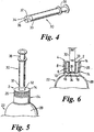
- a preferred embodiment of a bottle neck liner 2 of the first aspect of the invention comprises a sleeve 4 comprising circularly cylindrical wall 6 around which is located, in spaced-part relation, a circularly cylindrical concentric outer body 8 having at one end an outer taper or chamfer 10.
- the sleeve 4 and outer body 8 are connected at their upper ends by a top wall 12 which includes an outwardly protruding annular flange 14 which connects to the outer body 8 in the region of the chamfer.
- the sleeve 4 has a circularly cylindrical through bore 16.
- the sleeve 4 includes at the lower end thereof an inward step 18. This is an annular formation protruding inwardly from the interior surface of the sleeve 4 at its lower end, and terminating in a circular aperture 17. At its upper end the sleeve is inwardly bevelled at 20.
- the bottle neck liner 2 is a one-piece injection moulding from a resilient plastics material, typically of polypropylene or polyethylene.
- the bottle neck liner 2 is inserted into a bottle 22, which is preferably a medicine bottle for dispensing a viscous liquid medicine.
- the bottle is formed at its upper end with a cylindrical narrowed bottle neck 24, which is itself formed with an external screw thread 26.
- the bottle neck liner 2 is push fitted into the bottle neck 24 until the flange 14 of the bottle neck liner 2 abuts the rim of the bottle neck 24. At this point the bottle neck liner cannot be pushed further into the bottle neck 24.
- the bottle neck liner is dimensioned such that the sleeve 4 does not protrude past the bottle neck 24 and into the main body 28 of the bottle 22.
- the resilient nature of the plastics material of the bottle neck liner 2 means that as the liner is pushed into the bottle neck 24 the outer body 8 is deformed inwardly, and provides a sealing fit between the outer body 8 and the bottle neck 24. Thus, if the bottle 22 is inverted, no liquid can flow between the outer body 8 and the internal surface of the bottle neck 24.
- the flange 14 of the bottle neck liner 2 is dimensioned such that it has a diameter substantially identical to the diameter of the top surface of the bottle neck 24, and does not protrude to a significant degree past the bottle neck 24.
- a closure means such as a bottle cap (not shown) may be screwed onto the outer screw thread 26, over the bottle neck 24 and the bottle neck liner 2 within it, in order to sealingly close the bottle neck 24, for transportation, sale and storage.
- FIG. 4 illustrates a flat-nosed syringe 30 for use in the present invention.
- the flat-nosed syringe 30 includes a hollow circularly cylindrical syringe barrel 32 having a distal end region 33 to be received in the liner, and terminating in a perpendicular, circular face at its distal end 34, formed with a centrally located dispensing aperture 36.
- the syringe 30 also includes a plunger 38 arranged to move under reciprocal motion within the syringe barrel 32.
- the syringe barrel 32 is inserted into the bottle neck liner 2, as shown in Figure 5 .
- graduations on the syringe barrel 32 can still be seen by a user.
- the dispensing aperture 36 of the syringe barrel 32 is located centrally and contiguously with the opening within the inward step 10 of the sleeve 4.
- the bottle In use, in order to accurately measure and dispense an aliquot of liquid from the bottle 22, the bottle is tilted, or preferably inverted, and the plunger 38 of the syringe 30, previously stowed inside the barrel, is withdrawn until the prescribed aliquot of liquid has been drawn from the bottle 22, via aperture 17, into the syringe barrel 32, as measured by the graduations on the syringe barrel 32.
- the bottle may then be placed upright again, and the syringe 30 withdrawn from the bottle neck liner 2 in order to dispense the prescribed quantity of liquid now present in the syringe barrel 32.
- the bottle neck liner 2 allows for simple pouring of liquid from the bottle into a suitable receptacle such as a spoon or medicinal measuring cup.
- the syringe 30 is not used in this method, and the bottle is simply tilted or inverted such that liquid may flow through the annular space 21 formed within the inward step 10 of the bottle neck liner 2, and out of the bottle neck liner 2.
- the liquid dispensing apparatus exemplified in Figure 1 to 6 , can be used to dispense accurate aliquots of liquid through the flat-nosed syringe 18, or doses of liquid through the opening in the bottle neck liner 2, in the traditional way.
Claims (7)
- Appareil de distribution de liquide comprenant une bouteille (22), une doublure de goulot de bouteille (2) et une seringue à bout plat (30) ayant un plongeur (38) et un corps (32), le corps (32) se terminant à son extrémité distale (34) par une face généralement plate, ladite face plate étant perpendiculaire à l'axe longitudinal du corps (32), la bouteille (22) ayant un goulot de bouteille (24) dans lequel est disposée la doublure de goulot de bouteille (2) ayant un corps cylindrique (8) engagé de manière hermétique à l'intérieur du goulot (24) de la bouteille de telle sorte que du liquide ne puisse pas s'écouler entre la doublure de goulot de bouteille (2) et le goulot (24) de la bouteille, la doublure de goulot de bouteille (2) comprenant un manchon (4) comprenant, à son extrémité inférieure, un échelon interne (18) situé à l'intérieur du goulot (24) de la bouteille, une ouverture (17) étant définie à l'intérieur de l'échelon interne (18), le corps cylindrique (8) et le manchon (4) étant reliés l'un à l'autre par une bande de matériau uniquement au niveau de l'extrémité supérieure du corps cylindrique (8) et du manchon (4), le manchon (4) étant formé avec une portion évasée au niveau de son extrémité supérieure dans laquelle passe l'extrémité distale (34) du corps de seringue (32) ; et lorsque le corps (32) de la seringue est inséré dans le manchon (4), l'échelon interne (18) empêchant que le corps (32) de la seringue ne dépasse au-delà de l'échelon (18) et du liquide ne pouvant pas s'écouler entre le manchon (4) et le corps (32) mais pouvant quitter la bouteille (22) uniquement par le biais de l'ouverture (17) et donc de la seringue, et l'échelon interne (18) étant un échelon interne substantiellement annulaire (18), le manchon (4) étant dimensionné de telle sorte que lorsque le corps (32) de la seringue est inséré dans le manchon (4), le corps soit reçu de manière étanche à l'intérieur du manchon (4) et l'échelon interne (18) limitant le mouvement du corps (32).
- Appareil de distribution de liquide selon la revendication 1, dans lequel l'ouverture est préformée et est ouverte en permanence.
- Appareil de distribution de liquide selon l'une quelconque des revendications 1 ou 2, dans lequel le manchon comprend un matériau élastique.
- Appareil de distribution de liquide selon l'une quelconque des revendications précédentes, dans lequel la doublure comprend une bride faisant saillie vers l'extérieur s'étendant autour d'au moins une portion d'une extrémité de la doublure et butant contre le bord du goulot de la bouteille dans lequel est insérée la doublure.
- Appareil de distribution de liquide selon l'une quelconque des revendications précédentes, dans lequel la bouteille contient un médicament liquide.
- Appareil de distribution de liquide selon l'une quelconque des revendications précédentes, dans lequel la bouteille comporte un organe de fermeture qui peut être fixé par-dessus le goulot de la bouteille.
- Procédé de distribution de liquide à partir d'un appareil de distribution de liquide selon l'une quelconque des revendications précédentes, le procédé comprenant les étapes suivantes :(a) insérer le corps (32) de la seringue (30) dans la doublure (2) du goulot (24) d'une bouteille (22) jusqu'à ce que l'extrémité distale (34) du corps (32) bute contre l'échelon interne (18) substantiellement annulaire ;(b) positionner la bouteille (22) de telle sorte que du liquide à l'intérieur de la bouteille vienne en contact avec l'ouverture (17) dans la doublure (2) ;(c) effectuer un mouvement vers l'extérieur d'un plongeur (38) de la seringue (30) pour retirer du liquide de la bouteille (22) jusque dans le corps (32) ;(d) positionner la bouteille (22) de telle sorte que du liquide à l'intérieur de la bouteille (22) ne soit plus en contact avec l'ouverture ;(e) retirer le corps (32) de la doublure (2) du goulot (24) de la bouteille ; et(f) effectuer un mouvement vers l'intérieur du plongeur (38) de la seringue pour distribuer du liquide à partir du corps (32) de la seringue.
Applications Claiming Priority (2)
| Application Number | Priority Date | Filing Date | Title |
|---|---|---|---|
| GB0226347A GB0226347D0 (en) | 2002-11-12 | 2002-11-12 | Improvements in and relating to liquid dispensing |
| EP03775511.3A EP1560554B1 (fr) | 2002-11-12 | 2003-11-10 | Perfectionnements apportés et ayant trait à la distribution de liquides |
Related Parent Applications (3)
| Application Number | Title | Priority Date | Filing Date |
|---|---|---|---|
| EP03775511.3A Division-Into EP1560554B1 (fr) | 2002-11-12 | 2003-11-10 | Perfectionnements apportés et ayant trait à la distribution de liquides |
| EP03775511.3A Division EP1560554B1 (fr) | 2002-11-12 | 2003-11-10 | Perfectionnements apportés et ayant trait à la distribution de liquides |
| EP03775511.3 Division | 2003-11-10 |
Publications (3)
| Publication Number | Publication Date |
|---|---|
| EP2606870A2 EP2606870A2 (fr) | 2013-06-26 |
| EP2606870A3 EP2606870A3 (fr) | 2013-08-07 |
| EP2606870B1 true EP2606870B1 (fr) | 2017-03-22 |
Family
ID=9947656
Family Applications (2)
| Application Number | Title | Priority Date | Filing Date |
|---|---|---|---|
| EP13160349.0A Revoked EP2606870B1 (fr) | 2002-11-12 | 2003-11-10 | Perfectionnements apportés et ayant trait à la distribution de liquides |
| EP03775511.3A Revoked EP1560554B1 (fr) | 2002-11-12 | 2003-11-10 | Perfectionnements apportés et ayant trait à la distribution de liquides |
Family Applications After (1)
| Application Number | Title | Priority Date | Filing Date |
|---|---|---|---|
| EP03775511.3A Revoked EP1560554B1 (fr) | 2002-11-12 | 2003-11-10 | Perfectionnements apportés et ayant trait à la distribution de liquides |
Country Status (6)
| Country | Link |
|---|---|
| US (1) | US7284580B2 (fr) |
| EP (2) | EP2606870B1 (fr) |
| AU (1) | AU2003283537B2 (fr) |
| DK (1) | DK1560554T3 (fr) |
| GB (1) | GB0226347D0 (fr) |
| WO (1) | WO2004043326A1 (fr) |
Families Citing this family (10)
| Publication number | Priority date | Publication date | Assignee | Title |
|---|---|---|---|---|
| GB0226347D0 (en) | 2002-11-12 | 2002-12-18 | Boots Healthcare Int Ltd | Improvements in and relating to liquid dispensing |
| US20110252695A1 (en) * | 2010-04-14 | 2011-10-20 | Pryor Alan E | Bait Station Kit |
| ITPR20110045A1 (it) * | 2011-05-30 | 2012-12-01 | Bormioli Rocco & Figlio Spa | Riduttore. |
| US8870004B2 (en) | 2011-10-25 | 2014-10-28 | Target Brands, Inc. | Pharmacy bottle, system, and method |
| US8758322B2 (en) | 2011-10-25 | 2014-06-24 | Target Brands, Inc. | Dispensing insert for a medicine containment and dispensing system and associated method |
| FR2993174B1 (fr) | 2012-07-16 | 2014-07-25 | Rovipharm | Dispositif apte a securiser la distribution d'un liquide contenu dans un flacon |
| US20150337975A1 (en) * | 2014-05-23 | 2015-11-26 | Charles Allen | Inflation valve cap apparatus and method |
| US10436336B2 (en) * | 2014-11-13 | 2019-10-08 | Charles Allen | Cap with valve for inflation |
| FR3035080B1 (fr) | 2015-04-17 | 2019-08-09 | Centre Hospitalier Universitaire D'amiens-Picardie | Dispositif de bouchage pour permettre un prelevement d'une composition ensemble de conditionnement comprenant un tel dispositif de bouchage, procedes de prelevement et de conditionnement |
| CA3015885A1 (fr) | 2016-02-24 | 2017-08-31 | Neomed, Inc. | Raccord de transfert de fluide |
Citations (11)
| Publication number | Priority date | Publication date | Assignee | Title |
|---|---|---|---|---|
| USD260814S (en) | 1978-10-30 | 1981-09-15 | Abbott Laboratories | Syringe having a calibrated plunger |
| EP0542295A1 (fr) | 1991-11-15 | 1993-05-19 | Nissho Corporation | Récipients pour médicaments |
| WO1995001924A1 (fr) | 1993-07-08 | 1995-01-19 | Janssen Pharmaceutica N.V. | Dispositif doseur a l'epreuve des enfants |
| WO1995017874A1 (fr) | 1993-12-28 | 1995-07-06 | Thomas Lee Watson | Flacon dote d'un element de fermeture destine a recevoir une seringue |
| US5620434A (en) | 1994-03-14 | 1997-04-15 | Brony; Seth K. | Medicine vial link for needleless syringes |
| US6056135A (en) | 1997-12-16 | 2000-05-02 | Widman; Michael L. | Liquid transfer device to facilitate removal of liquid from a container by a syringe |
| US6179823B1 (en) | 1998-01-20 | 2001-01-30 | Bracco Research Usa | Multiple use universal connector flexible medical container assembly |
| USD445176S1 (en) | 2000-04-14 | 2001-07-17 | Milton E. Landers | Medicated cream and ointment dispenser with a ruled piston |
| DE10114423A1 (de) | 2001-03-13 | 2002-10-02 | Fresenius Kabi De Gmbh | Kunststoff-Flasche zur Aufnahme einer Flüssigkeit, insbesondere einer enteralen Nährlösung |
| WO2002085429A2 (fr) | 2001-04-24 | 2002-10-31 | Comar | Seringue pour enfant |
| EP1560554A1 (fr) | 2002-11-12 | 2005-08-10 | Boots Healthcare International Limited | Perfectionnements apportes et ayant trait a la distribution de liquides |
Family Cites Families (8)
| Publication number | Priority date | Publication date | Assignee | Title |
|---|---|---|---|---|
| GB693434A (en) | 1950-04-11 | 1953-07-01 | Alfred Clifford Sympson | Improvements relating to tapping bushes for casks |
| DE2023395C3 (de) | 1970-05-09 | 1980-09-25 | Schering Ag, 1000 Berlin Und 4619 Bergkamen | Gefäß mit Entnahmevorrichtung für luftempfindliche und/oder feuchtigkeitsempfindliche Flüssigkeiten |
| ATE73989T1 (de) * | 1982-02-08 | 1992-04-15 | Astra Laekemedel Ab | Mit normaldosis gefuellter behaelter. |
| FR2552404B1 (fr) * | 1983-09-26 | 1987-12-24 | Merck Sharp & Dohme | Ensemble de preparation et de delivrance d'une solution, bouchon obturateur pour cet ensemble et procede de fabrication de ce bouchon |
| GB2208227A (en) | 1988-08-11 | 1989-03-15 | Ici Plc | Introducing additive into a container |
| GB2268482B (en) | 1992-07-04 | 1994-06-29 | U B Plastics Limited | Shive |
| US5454805A (en) * | 1994-03-14 | 1995-10-03 | Brony; Seth K. | Medicine vial link for needleless syringes |
| DE19807847A1 (de) | 1998-02-25 | 1999-08-26 | Reipert | Spritzenaufsatz |
-
2002
- 2002-11-12 GB GB0226347A patent/GB0226347D0/en not_active Ceased
-
2003
- 2003-11-10 AU AU2003283537A patent/AU2003283537B2/en not_active Expired
- 2003-11-10 US US10/534,409 patent/US7284580B2/en not_active Expired - Lifetime
- 2003-11-10 DK DK03775511.3T patent/DK1560554T3/da active
- 2003-11-10 EP EP13160349.0A patent/EP2606870B1/fr not_active Revoked
- 2003-11-10 EP EP03775511.3A patent/EP1560554B1/fr not_active Revoked
- 2003-11-10 WO PCT/GB2003/004850 patent/WO2004043326A1/fr not_active Application Discontinuation
Patent Citations (11)
| Publication number | Priority date | Publication date | Assignee | Title |
|---|---|---|---|---|
| USD260814S (en) | 1978-10-30 | 1981-09-15 | Abbott Laboratories | Syringe having a calibrated plunger |
| EP0542295A1 (fr) | 1991-11-15 | 1993-05-19 | Nissho Corporation | Récipients pour médicaments |
| WO1995001924A1 (fr) | 1993-07-08 | 1995-01-19 | Janssen Pharmaceutica N.V. | Dispositif doseur a l'epreuve des enfants |
| WO1995017874A1 (fr) | 1993-12-28 | 1995-07-06 | Thomas Lee Watson | Flacon dote d'un element de fermeture destine a recevoir une seringue |
| US5620434A (en) | 1994-03-14 | 1997-04-15 | Brony; Seth K. | Medicine vial link for needleless syringes |
| US6056135A (en) | 1997-12-16 | 2000-05-02 | Widman; Michael L. | Liquid transfer device to facilitate removal of liquid from a container by a syringe |
| US6179823B1 (en) | 1998-01-20 | 2001-01-30 | Bracco Research Usa | Multiple use universal connector flexible medical container assembly |
| USD445176S1 (en) | 2000-04-14 | 2001-07-17 | Milton E. Landers | Medicated cream and ointment dispenser with a ruled piston |
| DE10114423A1 (de) | 2001-03-13 | 2002-10-02 | Fresenius Kabi De Gmbh | Kunststoff-Flasche zur Aufnahme einer Flüssigkeit, insbesondere einer enteralen Nährlösung |
| WO2002085429A2 (fr) | 2001-04-24 | 2002-10-31 | Comar | Seringue pour enfant |
| EP1560554A1 (fr) | 2002-11-12 | 2005-08-10 | Boots Healthcare International Limited | Perfectionnements apportes et ayant trait a la distribution de liquides |
Also Published As
| Publication number | Publication date |
|---|---|
| AU2003283537A1 (en) | 2004-06-03 |
| EP1560554A1 (fr) | 2005-08-10 |
| AU2003283537B2 (en) | 2007-12-06 |
| DK1560554T3 (da) | 2014-08-11 |
| EP2606870A3 (fr) | 2013-08-07 |
| GB0226347D0 (en) | 2002-12-18 |
| US7284580B2 (en) | 2007-10-23 |
| EP1560554B1 (fr) | 2014-05-07 |
| US20060027282A1 (en) | 2006-02-09 |
| WO2004043326A1 (fr) | 2004-05-27 |
| EP2606870A2 (fr) | 2013-06-26 |
Similar Documents
| Publication | Publication Date | Title |
|---|---|---|
| CA1285911C (fr) | Dispositif doseur-verseur de liquide | |
| US4077547A (en) | Measuring and dispensing apparatus | |
| US4747521A (en) | Dosage device | |
| US5316054A (en) | Self-contained package for housing, dispensing and diluting concentrated liquid | |
| AU684536B2 (en) | Childproof dosing device | |
| EP2606870B1 (fr) | Perfectionnements apportés et ayant trait à la distribution de liquides | |
| LV12925B (en) | Ophthalmic package and delivery device | |
| JPH0655623B2 (ja) | 分配送給容器 | |
| JPH05146483A (ja) | 薬の容器及び分配システム | |
| US10058484B2 (en) | Measured fluid dispenser | |
| JP2010509141A (ja) | 蓋及び分注システム | |
| US5381930A (en) | Dispensing device for a measured volume of liquid | |
| NZ335985A (en) | Measuring dispenser for a container | |
| EP2050501A1 (fr) | Embout de distribution de liquide avec réservoir | |
| US5988434A (en) | Dosage withdrawal apparatus | |
| US5119975A (en) | Drop volume dispensing closure | |
| US8826750B2 (en) | Method and device for the metered dispensing of a medium | |
| US20220289437A1 (en) | Liquid pouring spout | |
| EP0014283B1 (fr) | Récipient pour liquides et dispositif de fermeture | |
| WO2001036920A1 (fr) | Distributeur de liquide | |
| EP0552043A1 (fr) | Dispositif de dosage | |
| CA1112614A (fr) | Distributeur de liquide comprenant un contenant, une fermeture de securite et un dispositif de distribution du genre seringue | |
| CA2087402A1 (fr) | Dispositif de distribution | |
| WO2007074427A2 (fr) | Systeme de bouchons |
Legal Events
| Date | Code | Title | Description |
|---|---|---|---|
| 17P | Request for examination filed |
Effective date: 20130321 |
|
| AC | Divisional application: reference to earlier application |
Ref document number: 1560554 Country of ref document: EP Kind code of ref document: P |
|
| AK | Designated contracting states |
Kind code of ref document: A2 Designated state(s): AT BE BG CH CY CZ DE DK EE ES FI FR GB GR HU IE IT LI LU MC NL PT RO SE SI SK TR |
|
| PUAI | Public reference made under article 153(3) epc to a published international application that has entered the european phase |
Free format text: ORIGINAL CODE: 0009012 |
|
| REG | Reference to a national code |
Ref country code: DE Ref legal event code: R079 Ref document number: 60350056 Country of ref document: DE Free format text: PREVIOUS MAIN CLASS: A61J0001000000 Ipc: A61J0001140000 |
|
| PUAL | Search report despatched |
Free format text: ORIGINAL CODE: 0009013 |
|
| AK | Designated contracting states |
Kind code of ref document: A3 Designated state(s): AT BE BG CH CY CZ DE DK EE ES FI FR GB GR HU IE IT LI LU MC NL PT RO SE SI SK TR |
|
| RIC1 | Information provided on ipc code assigned before grant |
Ipc: A61J 1/14 20060101AFI20130701BHEP Ipc: A61J 1/20 20060101ALI20130701BHEP |
|
| GRAP | Despatch of communication of intention to grant a patent |
Free format text: ORIGINAL CODE: EPIDOSNIGR1 |
|
| INTG | Intention to grant announced |
Effective date: 20160108 |
|
| GRAP | Despatch of communication of intention to grant a patent |
Free format text: ORIGINAL CODE: EPIDOSNIGR1 |
|
| INTG | Intention to grant announced |
Effective date: 20160617 |
|
| STAA | Information on the status of an ep patent application or granted ep patent |
Free format text: STATUS: GRANT OF PATENT IS INTENDED |
|
| GRAS | Grant fee paid |
Free format text: ORIGINAL CODE: EPIDOSNIGR3 |
|
| GRAA | (expected) grant |
Free format text: ORIGINAL CODE: 0009210 |
|
| STAA | Information on the status of an ep patent application or granted ep patent |
Free format text: STATUS: THE PATENT HAS BEEN GRANTED |
|
| AC | Divisional application: reference to earlier application |
Ref document number: 1560554 Country of ref document: EP Kind code of ref document: P |
|
| AK | Designated contracting states |
Kind code of ref document: B1 Designated state(s): AT BE BG CH CY CZ DE DK EE ES FI FR GB GR HU IE IT LI LU MC NL PT RO SE SI SK TR |
|
| REG | Reference to a national code |
Ref country code: GB Ref legal event code: FG4D |
|
| REG | Reference to a national code |
Ref country code: CH Ref legal event code: EP |
|
| REG | Reference to a national code |
Ref country code: AT Ref legal event code: REF Ref document number: 876986 Country of ref document: AT Kind code of ref document: T Effective date: 20170415 |
|
| REG | Reference to a national code |
Ref country code: IE Ref legal event code: FG4D |
|
| REG | Reference to a national code |
Ref country code: DE Ref legal event code: R096 Ref document number: 60350056 Country of ref document: DE |
|
| REG | Reference to a national code |
Ref country code: RO Ref legal event code: EPE |
|
| REG | Reference to a national code |
Ref country code: NL Ref legal event code: MP Effective date: 20170322 |
|
| PG25 | Lapsed in a contracting state [announced via postgrant information from national office to epo] |
Ref country code: GR Free format text: LAPSE BECAUSE OF FAILURE TO SUBMIT A TRANSLATION OF THE DESCRIPTION OR TO PAY THE FEE WITHIN THE PRESCRIBED TIME-LIMIT Effective date: 20170623 Ref country code: FI Free format text: LAPSE BECAUSE OF FAILURE TO SUBMIT A TRANSLATION OF THE DESCRIPTION OR TO PAY THE FEE WITHIN THE PRESCRIBED TIME-LIMIT Effective date: 20170322 |
|
| REG | Reference to a national code |
Ref country code: AT Ref legal event code: MK05 Ref document number: 876986 Country of ref document: AT Kind code of ref document: T Effective date: 20170322 |
|
| PG25 | Lapsed in a contracting state [announced via postgrant information from national office to epo] |
Ref country code: BG Free format text: LAPSE BECAUSE OF FAILURE TO SUBMIT A TRANSLATION OF THE DESCRIPTION OR TO PAY THE FEE WITHIN THE PRESCRIBED TIME-LIMIT Effective date: 20170622 Ref country code: SE Free format text: LAPSE BECAUSE OF FAILURE TO SUBMIT A TRANSLATION OF THE DESCRIPTION OR TO PAY THE FEE WITHIN THE PRESCRIBED TIME-LIMIT Effective date: 20170322 |
|
| PG25 | Lapsed in a contracting state [announced via postgrant information from national office to epo] |
Ref country code: NL Free format text: LAPSE BECAUSE OF FAILURE TO SUBMIT A TRANSLATION OF THE DESCRIPTION OR TO PAY THE FEE WITHIN THE PRESCRIBED TIME-LIMIT Effective date: 20170322 |
|
| PG25 | Lapsed in a contracting state [announced via postgrant information from national office to epo] |
Ref country code: EE Free format text: LAPSE BECAUSE OF FAILURE TO SUBMIT A TRANSLATION OF THE DESCRIPTION OR TO PAY THE FEE WITHIN THE PRESCRIBED TIME-LIMIT Effective date: 20170322 Ref country code: ES Free format text: LAPSE BECAUSE OF FAILURE TO SUBMIT A TRANSLATION OF THE DESCRIPTION OR TO PAY THE FEE WITHIN THE PRESCRIBED TIME-LIMIT Effective date: 20170322 Ref country code: AT Free format text: LAPSE BECAUSE OF FAILURE TO SUBMIT A TRANSLATION OF THE DESCRIPTION OR TO PAY THE FEE WITHIN THE PRESCRIBED TIME-LIMIT Effective date: 20170322 Ref country code: CZ Free format text: LAPSE BECAUSE OF FAILURE TO SUBMIT A TRANSLATION OF THE DESCRIPTION OR TO PAY THE FEE WITHIN THE PRESCRIBED TIME-LIMIT Effective date: 20170322 Ref country code: SK Free format text: LAPSE BECAUSE OF FAILURE TO SUBMIT A TRANSLATION OF THE DESCRIPTION OR TO PAY THE FEE WITHIN THE PRESCRIBED TIME-LIMIT Effective date: 20170322 |
|
| REG | Reference to a national code |
Ref country code: DE Ref legal event code: R026 Ref document number: 60350056 Country of ref document: DE |
|
| PG25 | Lapsed in a contracting state [announced via postgrant information from national office to epo] |
Ref country code: PT Free format text: LAPSE BECAUSE OF FAILURE TO SUBMIT A TRANSLATION OF THE DESCRIPTION OR TO PAY THE FEE WITHIN THE PRESCRIBED TIME-LIMIT Effective date: 20170724 |
|
| PLBI | Opposition filed |
Free format text: ORIGINAL CODE: 0009260 |
|
| PLBI | Opposition filed |
Free format text: ORIGINAL CODE: 0009260 |
|
| 26 | Opposition filed |
Opponent name: ELM-PLASTIC GMBH Effective date: 20171127 |
|
| 26 | Opposition filed |
Opponent name: GLAXOSMITHKLINE CONSUMER HEALTHCARE (UK) IP LIMITE Effective date: 20171220 |
|
| PG25 | Lapsed in a contracting state [announced via postgrant information from national office to epo] |
Ref country code: DK Free format text: LAPSE BECAUSE OF FAILURE TO SUBMIT A TRANSLATION OF THE DESCRIPTION OR TO PAY THE FEE WITHIN THE PRESCRIBED TIME-LIMIT Effective date: 20170322 |
|
| PLAX | Notice of opposition and request to file observation + time limit sent |
Free format text: ORIGINAL CODE: EPIDOSNOBS2 |
|
| PG25 | Lapsed in a contracting state [announced via postgrant information from national office to epo] |
Ref country code: SI Free format text: LAPSE BECAUSE OF FAILURE TO SUBMIT A TRANSLATION OF THE DESCRIPTION OR TO PAY THE FEE WITHIN THE PRESCRIBED TIME-LIMIT Effective date: 20170322 |
|
| PLBB | Reply of patent proprietor to notice(s) of opposition received |
Free format text: ORIGINAL CODE: EPIDOSNOBS3 |
|
| PG25 | Lapsed in a contracting state [announced via postgrant information from national office to epo] |
Ref country code: MC Free format text: LAPSE BECAUSE OF FAILURE TO SUBMIT A TRANSLATION OF THE DESCRIPTION OR TO PAY THE FEE WITHIN THE PRESCRIBED TIME-LIMIT Effective date: 20170322 |
|
| PG25 | Lapsed in a contracting state [announced via postgrant information from national office to epo] |
Ref country code: CH Free format text: LAPSE BECAUSE OF NON-PAYMENT OF DUE FEES Effective date: 20171130 Ref country code: LI Free format text: LAPSE BECAUSE OF NON-PAYMENT OF DUE FEES Effective date: 20171130 |
|
| PG25 | Lapsed in a contracting state [announced via postgrant information from national office to epo] |
Ref country code: LU Free format text: LAPSE BECAUSE OF NON-PAYMENT OF DUE FEES Effective date: 20171110 |
|
| REG | Reference to a national code |
Ref country code: FR Ref legal event code: ST Effective date: 20180731 Ref country code: BE Ref legal event code: MM Effective date: 20171130 |
|
| REG | Reference to a national code |
Ref country code: IE Ref legal event code: MM4A |
|
| PG25 | Lapsed in a contracting state [announced via postgrant information from national office to epo] |
Ref country code: FR Free format text: LAPSE BECAUSE OF NON-PAYMENT OF DUE FEES Effective date: 20171130 Ref country code: IE Free format text: LAPSE BECAUSE OF NON-PAYMENT OF DUE FEES Effective date: 20171110 |
|
| PG25 | Lapsed in a contracting state [announced via postgrant information from national office to epo] |
Ref country code: BE Free format text: LAPSE BECAUSE OF NON-PAYMENT OF DUE FEES Effective date: 20171130 |
|
| PG25 | Lapsed in a contracting state [announced via postgrant information from national office to epo] |
Ref country code: HU Free format text: LAPSE BECAUSE OF FAILURE TO SUBMIT A TRANSLATION OF THE DESCRIPTION OR TO PAY THE FEE WITHIN THE PRESCRIBED TIME-LIMIT; INVALID AB INITIO Effective date: 20031110 |
|
| PLCK | Communication despatched that opposition was rejected |
Free format text: ORIGINAL CODE: EPIDOSNREJ1 |
|
| APAH | Appeal reference modified |
Free format text: ORIGINAL CODE: EPIDOSCREFNO |
|
| APBM | Appeal reference recorded |
Free format text: ORIGINAL CODE: EPIDOSNREFNO |
|
| APBP | Date of receipt of notice of appeal recorded |
Free format text: ORIGINAL CODE: EPIDOSNNOA2O |
|
| PG25 | Lapsed in a contracting state [announced via postgrant information from national office to epo] |
Ref country code: CY Free format text: LAPSE BECAUSE OF NON-PAYMENT OF DUE FEES Effective date: 20170322 |
|
| APBQ | Date of receipt of statement of grounds of appeal recorded |
Free format text: ORIGINAL CODE: EPIDOSNNOA3O |
|
| PG25 | Lapsed in a contracting state [announced via postgrant information from national office to epo] |
Ref country code: TR Free format text: LAPSE BECAUSE OF FAILURE TO SUBMIT A TRANSLATION OF THE DESCRIPTION OR TO PAY THE FEE WITHIN THE PRESCRIBED TIME-LIMIT Effective date: 20170322 |
|
| PGFP | Annual fee paid to national office [announced via postgrant information from national office to epo] |
Ref country code: GB Payment date: 20220922 Year of fee payment: 20 |
|
| PGFP | Annual fee paid to national office [announced via postgrant information from national office to epo] |
Ref country code: RO Payment date: 20221013 Year of fee payment: 20 Ref country code: IT Payment date: 20221011 Year of fee payment: 20 Ref country code: DE Payment date: 20220914 Year of fee payment: 20 |
|
| PLAB | Opposition data, opponent's data or that of the opponent's representative modified |
Free format text: ORIGINAL CODE: 0009299OPPO |
|
| R26 | Opposition filed (corrected) |
Opponent name: GLAXOSMITHKLINE CONSUMER HEALTHCARE (UK) IP LIMITED Effective date: 20171220 |
|
| PLAB | Opposition data, opponent's data or that of the opponent's representative modified |
Free format text: ORIGINAL CODE: 0009299OPPO |
|
| R26 | Opposition filed (corrected) |
Opponent name: ELM-PLASTIC GMBH Effective date: 20171127 |
|
| P01 | Opt-out of the competence of the unified patent court (upc) registered |
Effective date: 20230513 |
|
| REG | Reference to a national code |
Ref country code: DE Ref legal event code: R103 Ref document number: 60350056 Country of ref document: DE Ref country code: DE Ref legal event code: R064 Ref document number: 60350056 Country of ref document: DE |
|
| APBU | Appeal procedure closed |
Free format text: ORIGINAL CODE: EPIDOSNNOA9O |
|
| RDAF | Communication despatched that patent is revoked |
Free format text: ORIGINAL CODE: EPIDOSNREV1 |
|
| STAA | Information on the status of an ep patent application or granted ep patent |
Free format text: STATUS: PATENT REVOKED |
|
| RDAG | Patent revoked |
Free format text: ORIGINAL CODE: 0009271 |
|
| REG | Reference to a national code |
Ref country code: DE Ref legal event code: R071 Ref document number: 60350056 Country of ref document: DE |
|
| REG | Reference to a national code |
Ref country code: GB Ref legal event code: PE20 Expiry date: 20231109 |
|
| 27W | Patent revoked |
Effective date: 20230914 |
|
| PG25 | Lapsed in a contracting state [announced via postgrant information from national office to epo] |
Ref country code: GB Free format text: LAPSE BECAUSE OF EXPIRATION OF PROTECTION Effective date: 20231109 |
|
| PG25 | Lapsed in a contracting state [announced via postgrant information from national office to epo] |
Ref country code: GB Free format text: LAPSE BECAUSE OF EXPIRATION OF PROTECTION Effective date: 20231109 |