EP2606782A1 - Coffee/espresso machine with a milk foaming device for cappuccino - Google Patents
Coffee/espresso machine with a milk foaming device for cappuccino Download PDFInfo
- Publication number
- EP2606782A1 EP2606782A1 EP12007461.2A EP12007461A EP2606782A1 EP 2606782 A1 EP2606782 A1 EP 2606782A1 EP 12007461 A EP12007461 A EP 12007461A EP 2606782 A1 EP2606782 A1 EP 2606782A1
- Authority
- EP
- European Patent Office
- Prior art keywords
- nozzle
- espresso
- coffee
- outlet
- milk
- Prior art date
- Legal status (The legal status is an assumption and is not a legal conclusion. Google has not performed a legal analysis and makes no representation as to the accuracy of the status listed.)
- Granted
Links
- 239000008267 milk Substances 0.000 title claims abstract description 63
- 235000013336 milk Nutrition 0.000 title claims abstract description 63
- 210000004080 milk Anatomy 0.000 title claims abstract description 63
- 235000015114 espresso Nutrition 0.000 title claims abstract description 50
- 235000016213 coffee Nutrition 0.000 title claims abstract description 41
- 235000013353 coffee beverage Nutrition 0.000 title claims abstract description 41
- 235000015116 cappuccino Nutrition 0.000 title claims abstract description 7
- 238000005187 foaming Methods 0.000 title description 5
- 239000006260 foam Substances 0.000 claims abstract description 38
- 239000012530 fluid Substances 0.000 claims abstract 2
- 238000004140 cleaning Methods 0.000 description 5
- 238000009826 distribution Methods 0.000 description 5
- 239000000203 mixture Substances 0.000 description 5
- 230000015572 biosynthetic process Effects 0.000 description 4
- 238000002360 preparation method Methods 0.000 description 4
- 235000013361 beverage Nutrition 0.000 description 3
- 230000006835 compression Effects 0.000 description 3
- 238000007906 compression Methods 0.000 description 3
- 230000000694 effects Effects 0.000 description 3
- 238000004519 manufacturing process Methods 0.000 description 3
- XLYOFNOQVPJJNP-UHFFFAOYSA-N water Substances O XLYOFNOQVPJJNP-UHFFFAOYSA-N 0.000 description 2
- 230000001154 acute effect Effects 0.000 description 1
- 230000000295 complement effect Effects 0.000 description 1
- 239000006071 cream Substances 0.000 description 1
- 238000005520 cutting process Methods 0.000 description 1
- 235000020243 first infant milk formula Nutrition 0.000 description 1
- 238000003756 stirring Methods 0.000 description 1
- 238000003860 storage Methods 0.000 description 1
- 238000011144 upstream manufacturing Methods 0.000 description 1
Images

Classifications
-
- A—HUMAN NECESSITIES
- A47—FURNITURE; DOMESTIC ARTICLES OR APPLIANCES; COFFEE MILLS; SPICE MILLS; SUCTION CLEANERS IN GENERAL
- A47J—KITCHEN EQUIPMENT; COFFEE MILLS; SPICE MILLS; APPARATUS FOR MAKING BEVERAGES
- A47J31/00—Apparatus for making beverages
- A47J31/44—Parts or details or accessories of beverage-making apparatus
- A47J31/4485—Nozzles dispensing heated and foamed milk, i.e. milk is sucked from a milk container, heated and foamed inside the device, and subsequently dispensed from the nozzle
Abstract
Description
Die Erfindung betrifft eine Kaffee-/Espressomaschine mit einer Milchschaumerzeugungseinrichtung für Cappuccino nach dem Oberbegriff des Anspruchs 1.The invention relates to a coffee / espresso machine with a milk froth producing device for cappuccino according to the preamble of
Eine solche bekannte Kaffee-/Espressomaschine ist so ausgebildet, dass sie Milchschaum und Espresso auch zeitlich aufeinanderfolgend in eine Tasse oder zwei Tassen als Auffanggefäß(e) auf einer Aufstellfläche einleiten kann, ohne deren Umpositionierung zu erfordern, sowie leicht und gründlich gereinigt werden kann (
Bekannt ist auch ein Kaffeeautomat zur Ausgabe von Kaffee, Milch und/oder Milchschaum mit zumindest einem Kaffeezuführkanal und einem Milch-/Milchschaumzuführkanal mit zwei zueinander beabstandet angeordneten Kanalauslässen, deren gegenseitiger Abstand zum alternativen gemeinsamen Befüllen von zwei Getränkebehältern oder lediglich einem einzigen Getränkebehälter bemessen ist (
Die
Eine weitere bekannte Espressomaschine weist einen Auslaufverteiler nur für gebrühten Kaffee und aus diesem erzeugten Schaum, nicht aber Milchschaum, mit einer Schneide auf, die den Kaffee und Schaum auf zwei Ausläufe verteilt (
Der vorliegenden Erfindung liegt die Aufgabe zugrunde, die (Vor-)Reinigung des Auslaufverteilers mit den beiden Auslaufrohren gemeinsam für Kaffee und Milchschaum in konstruktiv einfacher Weise weiter zu verbessern und insbesondere eine Abnehmbarkeit des Auslaufverteilers zur Reinigung entbehrlich zu machen.The present invention has for its object to further improve the (pre-) cleaning of the outlet manifold with the two outlet pipes for coffee and milk foam in a structurally simple manner and in particular to make a removability of the outlet distributor for cleaning unnecessary.
Diese Aufgabe wird durch eine Kaffee-/Espressomaschine mit den Merkmalen des Anspruchs 1 gelöst.This object is achieved by a coffee / espresso machine with the features of
Es wird von einer Kaffee-/Espressomaschine mit einer Milchschaumerzeugungseinrichtung ausgegangen, die eine Venturidüse in einem Strömungskanal zwischen einer Dampfzuleitung und einer Misch- und Schäumkammer und einer in Durchflussrichtung auf diese folgende Düsenanordnung umfasst, die nach dem Prinzip einer Lavaldüse funktioniert. Eine solche Düsenanordnung weist einen Kompressionsraum in Durchflussrichtung vor einem Düsenhals und an diesen anschließend eine Expansionszone auf, die durch einen Expansionsraum der Düsenanordnung gebildet sein kann.It is assumed that a coffee / espresso machine with a milk froth generating device comprising a Venturi nozzle in a flow channel between a steam supply line and a mixing and Schäumkammer and a flow direction in the following nozzle assembly which works on the principle of a Laval nozzle. Such a nozzle arrangement has a compression space in the direction of flow in front of a nozzle neck and to this then an expansion zone, which may be formed by an expansion space of the nozzle assembly.
Indem eine solche Düsenanordnung der Milchschaumerzeugungseinrichtung erfindungsgemäß direkt in einen mittigen Verbindungsabschnitt eines Verteilerrohrs eines Auslaufverteilers mündet, entfällt jedwede gesonderte Milchschaumzuführleitung zu dem Auslaufverteiler, der bereits zur Auslaufverteilung von Kaffee/Espresso vorgesehen ist. Der Herstellungsaufwand ist entsprechend gering. Betriebstechnisch entfällt nicht nur ein Reinigungserfordernis für sonst erforderliche Milch/Milchschaum führende Leitungen, sondern zumindest der aus Verteilerrohr und Auslaufrohren bestehende Auslaufverteiler kann mit Kaffee/Espresso, der insbesondere für Cappuccinobereitung in wenigstens ein Auffanggefäß bzw. eine Tasse nach Milchschaumeinleitung geleitet wird, wirksam gespült werden und im Bedarfsfall weiter mit Wasser gereinigt werden.According to the invention, by virtue of such a nozzle arrangement of the milk foam generating device opening directly into a central connecting section of a distributor pipe of an outlet distributor, any separate milk foam feed line to the outlet distributor, which is already provided for the outlet distribution of coffee / espresso, is dispensed with. The production cost is correspondingly low. Operationally eliminates not only a cleaning requirement for otherwise required milk / milk foam leading lines, but at least the distribution manifold and outlet pipes existing outlet distributor can be effectively flushed with coffee / espresso, which is directed in particular for cappuccino preparation in at least one receptacle or a cup after milk foam introduction and if necessary continue to clean with water.
Außerdem ist eine Baugruppe mit einer solchen Anordnung des Auslaufverteilers besonders kompakt.In addition, an assembly with such an arrangement of the outlet manifold is particularly compact.
Bevorzugt mündet der Espressozulauf für den mit dem Auslaufverteiler zu verteilenden Espresso zum wirksamen Spülen nicht nur des Auslaufverteilers, sondern auch zumindest teilweise der Düsenanordnung nach Anspruch 2 in den Düsenhals der Düsenanordnung oder stromabwärts des Düsenhalses in einen Expansionsraum der Düsenanordnung, also in beiden Fällen in einen Bereich der Düsenanordnung, in dem der zugeführte Espresso beschleunigt wird.Preferably, the espresso inlet for the espresso to be distributed with the outlet distributor for effective rinsing not only the outlet manifold, but also at least partially the nozzle assembly of
Es ist statt dessen nach Anspruch 7 möglich, den Espressozulauf getrennt von der Düsenanordnung in den Verbindungsabschnitt des Verteilerrohrs münden zu lassen, wodurch eine Spülung mit Espresso erst in dem Verbindungsabschnitt einsetzen kann.It is instead possible according to
Eine herstellungsgünstige kompakte Gestaltung der dem Auslaufverteiler vorgeschalteten Düsenanordnung der Milchschaumerzeugungseinrichtung wird gemäß Anspruch 3 dadurch erzielt, dass der Düsenhals der Düsenanordnung hohlzylindrisch bis zu dem Verbindungsabschnitt des Verteilerrohrs verlängert ist. Dabei dienen düsennahe Abschnitte des Verteilerrohrs einschließlich des Verbindungsabschnitts als Expansionszonen.A low-production compact design of the outlet manifold upstream nozzle assembly of the milk froth generating device is achieved according to
Als Verbindungsabschnitt des Verteilerrohrs wird dessen rohrförmiger Abschnitt angesehen, der die seitliche Mündung der Düsenanordnung begrenzt.As the connecting portion of the manifold, the tubular portion is considered, which limits the lateral mouth of the nozzle assembly.
Bei dieser Ausbildung des Düsenhalses nach Anspruch 3 mündet in diesen quer ein Espressozulauf, der einfach in Form einer Bohrung ausgeführt sein kann. Auch der verlängerte Düsenhals ist zweckmäßig als Bohrung realisiert.In this embodiment of the nozzle neck according to
Für die Ausbildung der vorgenannten Expansionszonen in dem Verteilerrohr ist nach Anspruch 4 die lichte Querschnittsfläche des Verteilerrohrs zumindest an dessen Verbindungsabschnitt größer als diejenige des zu dem Verbindungsabschnitt verlängerten Düsenhalses.For the formation of the aforementioned expansion zones in the manifold according to
In einer Variante der Kaffee-/Espressomaschine nach Anspruch 5 erstreckt sich eine sich an den Düsenhals in Durchflussrichtung anschließender und in seiner Querschnittsfläche erweiternder Expansionsraum der Düsenanordnung bis in den Verbindungsabschnitt des Verteilerrohrs. In dieser Variante kann der Expansionsraum praktisch unabhängig von der Ausbildung des Verteilerrohrs optimiert werden.In a variant of the coffee / espresso machine according to claim 5, an expansion space of the nozzle arrangement which adjoins the nozzle throat in the direction of flow and which widens in its cross-sectional area extends into the connecting section of the distributor tube. In this variant, the expansion space can be optimized practically independent of the formation of the manifold.
Bevorzugt bei letzterer Variante kann nach Anspruch 6 eine Kaffeezulaufleitung sich bis in den Düsenhals erstrecken und in diesem als Schlitzdüse ausgebildet sein. Der gegenüber dem inneren Querschnitt der Espressozulaufleitung engere Schlitz der Schlitzdüse befindet sich auf der dem Expansionsraum der Düsenanordnung zugewandten Seite der Espressozulaufleitung und verläuft quer zur Durchflussrichtung des Milch-/Luftgemischs bzw. Milchschaums durch den Düsenhals. Durch die Anordnung der Schlitzdüse in dem Düsenhals wirkt der Expansionsraum der Milchschäumvorrichtung zugleich als Expansionszone der Schlitzdüse, wobei die Expansionszone noch weiter düsennahe Abschnitte einschließlich des Verbindungsabschnitts des Verteilerrohrs umfassen kann. Vorteilhaft bei dieser Anordnung ist, dass der der Schlitzdüse zugeführte Kaffeesud in der Schlitzdüse komprimiert wird und nachfolgend entspannt wird, was zu einer weiter verbesserten Cremabildung führt.Preferably, in the latter variant can according to claim 6, a coffee supply line extending into the nozzle throat and be formed in this as a slot nozzle. The closer to the inner cross section of the Espressozulaufleitung slit of the slot nozzle is located on the expansion space of the nozzle assembly facing side of Espressozulaufleitung and extends transversely to the flow direction of the milk / air mixture or milk foam through the nozzle neck. Due to the arrangement of the slot nozzle in the nozzle neck, the expansion space of the milk foaming device simultaneously acts as an expansion zone of the slot nozzle, wherein the expansion zone may comprise further nozzle-near sections including the connection section of the distributor tube. An advantage of this arrangement is that the slotted nozzle supplied coffee is compressed in the slit and is subsequently relaxed, resulting in a further improved cream formation.
Drei Ausführungsformen einer Baueinheit einer Milchschaumerzeugungseinrichtung für Cappuccino mit einem zwei Auslaufrohre umfassenden Auslaufverteiler für eine Kaffee-/Espressomaschine werden nachfolgend anhand einer Zeichnung mit drei Figuren beschrieben, aus denen sich weitere vorteilhafte Merkmale der Erfindung ergeben können. Es zeigen:
- Fig. 1
- eine erste Ausführungsform einer Baueinheit einer Milchschaumerzeugungseinrichtung, die direkt in einen Auslaufverteiler mündet, in einem Längsschnitt,
- Fig. 1 a
- einen Ausschnitt aus der Milchschaumerzeugungseinrichtung nach
Figur 1Figur 1 - Fig. 1 b
- als Einzelheit der ersten Ausführungsform aus den
Figuren 1 und 1aFigur 1 a, - Fig. 2
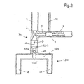
- eine zweite Ausführungsform einer direkt in einen Auslaufverteiler mündenden Milchschaumerzeugungseinrichtung in einem Längsschnitt und
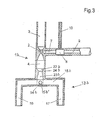
- Fig. 3
- eine dritte Ausführungsform einer direkt in einen Auslaufverteiler mündenden Milchschaumerzeugungseinrichtung in einem Längsschnitt.
- Fig. 1
- a first embodiment of a structural unit of a milk foam generating device, which opens directly into an outlet distributor, in a longitudinal section,
- Fig. 1 a
- a section of the milk froth generating device according to
FIG. 1 in a sectional plane AA in oppositeFIG. 1 larger picture, - Fig. 1 b
- as a detail of the first embodiment of the
Figures 1 and 1a , an espresso inlet formed as a slot nozzle in a cross-section in the sectional plane BB in FIGFIG. 1 a, - Fig. 2
- a second embodiment of an opening directly into an outlet distributor milk froth generating device in a longitudinal section and
- Fig. 3
- a third embodiment of an opening directly into an outlet distributor milk froth generating device in a longitudinal section.
In den Figuren sind gleiche Teile mit übereinstimmenden Bezugszeichen versehen.In the figures, like parts are provided with corresponding reference numerals.
In
Die grundlegende Funktion der Milchschaumerzeugungseinrichtung besteht darin, dass durch Dampf, der in die Dampfzuleitung 3 einströmt, in die Venturidüse 2 Milchluftgemisch oder aber bei geschlossener Luftleitung 10 Milch angesaugt wird und in der Schäumkammer zu Milchschaum bzw. erhitzter Milch aufbereitet wird.The basic function of the milk foam generating device is that steam is sucked into the
Die Milchschaumerzeugungseinrichtung 1 umfasst auf die Misch- und Schäumkammer in Durchflussrichtung D folgend eine Düsenanordnung 22 nach dem Laval-Prinzip, die einen sich in Durchflussrichtung D an die Misch- und Schäumkammer anschließende, nicht bezeichneten Kompressionsraum vor und einen Expansionsraum 23 nach einem Düsenhals 24 aufweist. Der Kompressionsraum und der Expansionsraum 23 sind, wie in
Ein Auslaufverteiler 13 der Baueinheit dieser Milchschaumerzeugungseinrichtung 1 umfasst ein im Wesentlichen mittig angeordnetes Verteilerrohr 15, an dessen beiden Enden je ein Auslaufrohr 16 bzw. 17 vertikal nach unten abgewinkelt angeordnet ist und über einer nicht dargestellten gemeinsamen Abstellfläche für Tassen und dergleichen Auffanggefäße unten offen ist.An
Wie aus
Düsennahe Abschnitte des Verteilerrohrs 15, insbesondere der Verbindungsabschnitt 15a, können dabei noch die Expansionswirkung des Expansionsraums 23 ergänzen.Düsennahe sections of the manifold 15, in particular the connecting
Aus den
Der Kaffeesud strömt dann, wie vorzugsweise vorangehend, der Milchschaum, aus dem Expansionsraum 23 der Milchschaumerzeugungseinrichtung 1 direkt in den Verbindungsabschnitt 15a des Verbindungsrohrs 15 des Auslaufverteilers 13, in dem er gleichmäßig in die beiden Auslaufrohre 16, 17 verteilt wird. Aus jedem der beiden Auslaufrohre 16, 17 fließt also ein gleichmäßig aufgeteilter Anteil Milchschaum und Espresso in jeweils ein Auffanggefäß oder ein geeignet aufgestelltes gemeinsames Auffanggefäß.The coffee sud then flows, as preferably before, the milk foam, from the
Die Milchschaumerzeugungseinrichtung 1a der zweiten Ausführungsform unterscheidet sich von der Milchschaumerzeugungseinrichtung 1 der ersten Ausführungsform durch die Ausbildung des Düsenhalses 25 der Düsenanordnung 22a nach dem Laval-Prinzip in
In den verlängerten Düsenhals 25 der Düsenanordnung 22a erstreckt sich ein einfacher Espressozulauf 14a in Form einer Bohrung, so dass der austretende Espresso in dem verlängerten Düsenhals 25 und der anschließenden Expansionszone in dem Verteilerrohr 15a, insbesondere dem Verbindungsabschnitt 15a', beschleunigt wird und die sich an den Espressozulauf 14a in Durchflussrichtung D anschließenden Abschnitte des Düsenhalses 25 und des Auslaufverteilers 15 wirksam spülen kann.In the
Die dritte Ausführungsform der Milchschaumerzeugungseinrichtung 1b und des Auslaufverteilers 13b in
Somit können in der dritten Ausführungsform das Verteilerrohr 15b, das auch zur Leitung von Milchschaum dient, anschließend zusammen mit den Auslaufrohren 16 und 17 durch Kaffee/Espresso gespült werden.Thus, in the third embodiment, the manifold 15b, which also serves to direct milk froth, can then be rinsed together with the
- 11
- MilchschaumerzeugungseinrichtungMilk foam generator
- 1 a1 a
- MilchschaumerzeugungseinrichtungMilk foam generator
- 1 b1 b
- MilchschaumerzeugungseinrichtungMilk foam generator
- 22
- Venturidüseventuri
- 33
- Dampfzuleitungsteam supply
- 44
- Misch- und SchäumkammerMixing and foaming chamber
- 77
- MilchluftgemischleitungMilk air mixture line
- 88th
- MilchluftvormischkammerMilchluftvormischkammer
- 99
- MilchzulaufleitungMilk supply line
- 1010
- Luftleitungair line
- 1313
- Auslaufverteileroutflow distributor
- 1414
- Espressozulaufespresso feed
- 14a14a
- Espressozulauf (Schlitzdüse)Espresso feed (slot nozzle)
- 14b14b
- Espressozulaufespresso feed
- 1515
- Verteilerrohrmanifold
- 15'15 '
- Verbindungsabschnittconnecting portion
- 15a15a
- Espresso-MilchschaumverteilerrohrEspresso froth manifold
- 15a'15a '
- Verbindungsabschnittconnecting portion
- 15b15b
- Verteilerrohrmanifold
- 15b'15b '
- Verbindungsabschnittconnecting portion
- 1616
- Auslaufrohroutlet pipe
- 1717
- Auslaufrohroutlet pipe
- 2222
- (Laval-)Düsenanordnung(Laval) nozzle assembly
- 22a22a
- (Laval-)Düsenanordnung(Laval) nozzle assembly
- 22b22b
- (Laval-)Düsenanordnung(Laval) nozzle assembly
- 2323
- Expansionsraumexpansion space
- 23b23b
- Expansionsraumexpansion space
- 2424
- Düsenhalsnozzle throat
- 24b24b
- Düsenhalsnozzle throat
- 2525
- verlängerter Düsenhalsextended nozzle throat
- 114114
- EspressozulaufleitungEspresso supply line
Claims (7)
wobei der Espressozulauf (14, 14a, 14b) an einem Ausgang einer Espressobrüheinheit angeschlossen ist,
wobei ein Auslaufverteiler (13, 13a, 13b) die zwei Auflaufrohre (16, 17) aufweist und mit dem Espressozulauf (14, 14a, 14b) flüssigkeitsleitend verbunden ist,
wobei von Enden eines Verteilerrohrs (15, 15a, 15b) des Auslaufverteilers (13, 13a, 13b) die Auslaufrohre (16, 17) nach unten abgewinkelt angeordnet sind und unten offen sind, und
wobei die Milchschaumerzeugungseinrichtung (1, 1a, 1b), die eine Venturidüse (2), eine Misch- und Schäumkammer (4) und eine auf diese in Durchflussrichtung folgende Düsenanordnung (22, 22a, 22b) nach dem Laval-Prinzip mit einem Düsenhals umfasst, mit dem Auslaufverteiler (13, 13a, 13b) in flüssigkeitsleitender Verbindung steht,
dadurch gekennzeichnet,
dass die Düsenanordnung (22, 22a, 22b) der Milchschaumerzeugungseinrichtung (1, 1 a, 1 b) direkt in einen mittigen Verbindungsabschnitt (15', 15a', 15b') des Verteilerrohrs (15, 15a, 15b) mündet.Coffee / espresso machine with a milk foam generating device (1, 1 a, 1 b) for cappuccino and with two outlet pipes (16, 17) in fluid communication with an espresso feed (14, 14 a, 14 b),
the espresso feed (14, 14a, 14b) being connected to an exit of an espresso brewing unit,
an outlet distributor (13, 13a, 13b) having the two overflow tubes (16, 17) and being connected in a fluid-conducting manner to the espresso inlet (14, 14a, 14b),
wherein from ends of a manifold (15, 15a, 15b) of the outlet manifold (13, 13a, 13b), the outlet pipes (16, 17) are arranged angled downwards and are open at the bottom, and
wherein the milk froth generating means (1, 1a, 1b) comprising a venturi nozzle (2), a mixing and frothing chamber (4) and a nozzle arrangement (22, 22a, 22b) following the same in the flow direction with a nozzle throat according to the Laval principle with the outlet distributor (13, 13a, 13b) in liquid-conducting connection,
characterized,
in that the nozzle arrangement (22, 22a, 22b) of the milk foam generating device (1, 1a, 1b) opens directly into a central connecting section (15 ', 15a', 15b ') of the distributor tube (15, 15a, 15b).
dadurch gekennzeichnet,
dass der Espressozulauf (14, 14a, 14b) in den Düsenhals (24, 24b, 25) der Düsenanordnung (22, 22a, 22b) oder stromabwärts des Düsenhalses (24, 24b, 25) in eine Expansionszone (23, 23b) der Düsenanordnung (22, 22a, 22b) mündet.Coffee / espresso machine according to claim 1,
characterized,
that the espresso inlet (14, 14a, 14b) in the nozzle throat (24, 24b, 25) of the nozzle assembly (22, 22a, 22b) or downstream of the nozzle throat (24, 24b, 25) in an expansion zone (23, 23b) of the nozzle assembly (22, 22a, 22b) opens.
dadurch gekennzeichnet,
dass der Düsenhals (25) der Düsenanordnung (22a) hohlzylindrisch verlängert ist, so dass er sich bis in den Verbindungsabschnitt (15a') des Verteilerrohrs (15a) erstreckt.Coffee / espresso machine according to claim 2,
characterized,
in that the nozzle throat (25) of the nozzle arrangement (22a) is hollow-cylindrical, so that it extends into the connection section (15a ') of the distributor tube (15a).
dadurch gekennzeichnet,
dass die lichte Querschnittsfläche des Verteilerrohrs (15a) zumindest an dem Verbindungsabschnitt (15a') größer als diejenige des verlängerten Düsenhalses (25) ist.Coffee / espresso machine according to claim 3,
characterized,
in that the clear cross-sectional area of the distributor tube (15a), at least at the connecting portion (15a '), is greater than that of the extended nozzle throat (25).
dadurch gekennzeichnet,
dass sich ein an den Düsenhals (24, 24b) in Durchflussrichtung (D) anschließender und im Verlauf der Durchflussrichtung (D) in seiner Querschnittsfläche erweiternder Expansionsraum (23, 23b) in der Düsenanordnung (13, 13b) bis in den Verbindungsabschnitt (15', 15b') des Verteilerrohrs (15, 15b) erstreckt.Coffee / espresso machine according to one of claims 1 - 3,
characterized,
in that an expansion space (23, 23b) adjoining the nozzle throat (24, 24b) in the flow direction (D) and widening in its cross-sectional area in the flow direction (D) extends in the nozzle arrangement (13, 13b) into the connecting section (15 '; , 15b ') of the manifold (15, 15b).
dadurch gekennzeichnet,
dass eine sich bis in den Düsenhals (24) erstreckende Espressozulaufleitung (114) als Schlitzdüse ausgebildet ist.Coffee / espresso machine according to claim 5,
characterized,
in that an espresso feed line (114) extending into the nozzle throat (24) is designed as a slot nozzle.
dadurch gekennzeichnet,
dass der Espressozulauf (14b) in den Verbindungsabschnitt (15b') des Verteilerrohrs (15b) mündet.Coffee / espresso machine according to claim 2,
characterized,
in that the espresso inlet (14b) opens into the connecting section (15b ') of the distributor tube (15b).
Applications Claiming Priority (1)
| Application Number | Priority Date | Filing Date | Title |
|---|---|---|---|
| DE201120109479 DE202011109479U1 (en) | 2011-12-22 | 2011-12-22 | Coffee / espresso machine with a milk froth maker for cappuccino |
Publications (2)
| Publication Number | Publication Date |
|---|---|
| EP2606782A1 true EP2606782A1 (en) | 2013-06-26 |
| EP2606782B1 EP2606782B1 (en) | 2015-08-05 |
Family
ID=45832968
Family Applications (1)
| Application Number | Title | Priority Date | Filing Date |
|---|---|---|---|
| EP12007461.2A Active EP2606782B1 (en) | 2011-12-22 | 2012-10-31 | Coffee/espresso machine with a milk foaming device for cappuccino |
Country Status (5)
| Country | Link |
|---|---|
| US (1) | US20130160657A1 (en) |
| EP (1) | EP2606782B1 (en) |
| CN (1) | CN103169373B (en) |
| DE (1) | DE202011109479U1 (en) |
| ES (1) | ES2546519T3 (en) |
Cited By (3)
| Publication number | Priority date | Publication date | Assignee | Title |
|---|---|---|---|---|
| EP3155937A1 (en) | 2015-10-15 | 2017-04-19 | Seb S.A. | Beverage dispensing device with dual output and coffee machine comprising such a device |
| EP3878320A1 (en) | 2020-03-12 | 2021-09-15 | Seb S.A. | Automatic coffee machine equipped with a device for draining the coffee discharge conduit |
| EP3960042A1 (en) | 2020-08-27 | 2022-03-02 | Seb S.A. | Process for making frothed coffee from an automatic coffee machine equipped with a frothing device |
Families Citing this family (17)
| Publication number | Priority date | Publication date | Assignee | Title |
|---|---|---|---|---|
| BR112015000334A2 (en) * | 2012-07-12 | 2017-06-27 | Koninklijke Philips Nv | foaming device in a liquid by interaction with a gas, beverage preparation device and coffee maker |
| DE202012104836U1 (en) | 2012-12-12 | 2013-01-04 | Eugster/Frismag Ag | Milk foaming device with external milk supply |
| DE102013212844A1 (en) * | 2013-07-02 | 2015-01-08 | BSH Bosch und Siemens Hausgeräte GmbH | Emulsifying device for a milk frother of a coffee machine |
| WO2016001047A1 (en) * | 2014-06-30 | 2016-01-07 | Koninklijke Philips N.V. | Coffee dispensing apparatus |
| CN105768910B (en) * | 2014-12-22 | 2018-03-30 | 杜文娟 | Utilize the automatic gradation priming apparatus of spiral suction pump |
| CN105768901B (en) * | 2014-12-22 | 2017-12-05 | 杜文娟 | The design method of the unpowered priming apparatus of Venturi effect control |
| CN105768895B (en) * | 2014-12-22 | 2017-12-05 | 杜文娟 | Utilize the automatic gradation priming apparatus of Venturi effect |
| CN105768896B (en) * | 2014-12-22 | 2017-12-05 | 杜文娟 | Utilize the application method of the automatic gradation priming apparatus of Venturi effect |
| CN105768902B (en) * | 2014-12-22 | 2017-12-05 | 杜文娟 | The automatic gradation priming apparatus of steam wheel drive |
| CN105768911B (en) * | 2014-12-22 | 2018-03-30 | 杜文娟 | Utilize steam and the automatic gradation priming apparatus of screw pump |
| CN105768912B (en) * | 2014-12-22 | 2018-03-20 | 杜文娟 | Utilize the automatic gradation priming apparatus of bernoulli principle |
| CN104997410B (en) * | 2015-08-21 | 2018-03-27 | 苏州工业园区咖乐美电器有限公司 | Milk preparation device and coffee machine |
| CN104997414B (en) * | 2015-08-21 | 2018-09-21 | 苏州工业园区咖乐美电器有限公司 | Milk foam generator and coffee machine |
| JP6675070B2 (en) * | 2016-03-10 | 2020-04-01 | パナソニックIpマネジメント株式会社 | Beverage production equipment |
| DE102017203481B3 (en) * | 2017-03-03 | 2018-06-21 | BSH Hausgeräte GmbH | The beverage maker |
| CN111065277A (en) | 2017-07-11 | 2020-04-24 | 努布鲁有限责任公司 | Method and apparatus for improving consistency of espresso |
| CN113455902B (en) * | 2020-03-31 | 2022-05-17 | 宁波方太厨具有限公司 | Milk foam foaming device and coffee machine comprising same |
Citations (6)
| Publication number | Priority date | Publication date | Assignee | Title |
|---|---|---|---|---|
| DE4037366A1 (en) | 1990-11-23 | 1992-05-27 | Bosch Siemens Hausgeraete | Espresso coffee machine with foam producing element - uses steam as drive for foaming device |
| EP0820715A1 (en) * | 1996-07-22 | 1998-01-28 | Wmf Württembergische Metallwarenfabrik Ag | Coffee machine |
| DE202005011203U1 (en) * | 2005-07-16 | 2005-09-22 | Eugster/Frismag Ag | Dispenser for espresso machine comprises two outlet tubes connected by horizontal pipes to central feed pipe, tops of tubes being sealed, forming baffle chambers in which large bubbles in the milk are broken up, improving flow |
| DE202009013064U1 (en) * | 2009-09-29 | 2010-02-11 | Eugster/Frismag Ag | Coffee / espresso machine with a milk froth maker for cappuccino |
| EP2186454A1 (en) | 2008-11-07 | 2010-05-19 | BSH Bosch und Siemens Hausgeräte GmbH | Coffee machine |
| DE102010038112A1 (en) | 2010-10-12 | 2011-05-19 | SEVERIN ELEKTROGERÄTE GmbH | Electrical beverage preparing machine, particularly for preparation of coffee, espresso, flavored milk, has connector plate that is fixed within outlet housing part |
Family Cites Families (2)
| Publication number | Priority date | Publication date | Assignee | Title |
|---|---|---|---|---|
| NL1020834C2 (en) * | 2002-06-12 | 2003-12-15 | Sara Lee De Nv | Device and method for preparing a beverage suitable for consumption with a fine-bubble froth layer. |
| DE102009013937A1 (en) * | 2009-03-19 | 2010-09-23 | Wmf Württembergische Metallwarenfabrik Ag | frothing |
-
2011
- 2011-12-22 DE DE201120109479 patent/DE202011109479U1/en not_active Expired - Lifetime
-
2012
- 2012-10-31 ES ES12007461.2T patent/ES2546519T3/en active Active
- 2012-10-31 EP EP12007461.2A patent/EP2606782B1/en active Active
- 2012-12-20 US US13/722,664 patent/US20130160657A1/en not_active Abandoned
- 2012-12-21 CN CN201210559939.2A patent/CN103169373B/en active Active
Patent Citations (7)
| Publication number | Priority date | Publication date | Assignee | Title |
|---|---|---|---|---|
| DE4037366A1 (en) | 1990-11-23 | 1992-05-27 | Bosch Siemens Hausgeraete | Espresso coffee machine with foam producing element - uses steam as drive for foaming device |
| EP0820715A1 (en) * | 1996-07-22 | 1998-01-28 | Wmf Württembergische Metallwarenfabrik Ag | Coffee machine |
| DE202005011203U1 (en) * | 2005-07-16 | 2005-09-22 | Eugster/Frismag Ag | Dispenser for espresso machine comprises two outlet tubes connected by horizontal pipes to central feed pipe, tops of tubes being sealed, forming baffle chambers in which large bubbles in the milk are broken up, improving flow |
| EP2186454A1 (en) | 2008-11-07 | 2010-05-19 | BSH Bosch und Siemens Hausgeräte GmbH | Coffee machine |
| DE202009013064U1 (en) * | 2009-09-29 | 2010-02-11 | Eugster/Frismag Ag | Coffee / espresso machine with a milk froth maker for cappuccino |
| EP2301396A1 (en) | 2009-09-29 | 2011-03-30 | Eugster/Frismag AG | Coffee/espresso machine with a milk foaming device for cappuccino |
| DE102010038112A1 (en) | 2010-10-12 | 2011-05-19 | SEVERIN ELEKTROGERÄTE GmbH | Electrical beverage preparing machine, particularly for preparation of coffee, espresso, flavored milk, has connector plate that is fixed within outlet housing part |
Cited By (6)
| Publication number | Priority date | Publication date | Assignee | Title |
|---|---|---|---|---|
| EP3155937A1 (en) | 2015-10-15 | 2017-04-19 | Seb S.A. | Beverage dispensing device with dual output and coffee machine comprising such a device |
| FR3042397A1 (en) * | 2015-10-15 | 2017-04-21 | Seb Sa | DEVICE FOR DISPENSING DOUBLE-OUTLED BEVERAGES AND COFFEE MACHINE COMPRISING SUCH A DEVICE |
| EP3878320A1 (en) | 2020-03-12 | 2021-09-15 | Seb S.A. | Automatic coffee machine equipped with a device for draining the coffee discharge conduit |
| FR3108020A1 (en) | 2020-03-12 | 2021-09-17 | Seb S.A. | AUTOMATQUE COFFEE MACHINE EQUIPPED WITH A PURGE DEVICE FOR THE COFFEE DISCHARGE DUCT |
| EP3960042A1 (en) | 2020-08-27 | 2022-03-02 | Seb S.A. | Process for making frothed coffee from an automatic coffee machine equipped with a frothing device |
| FR3113573A1 (en) | 2020-08-27 | 2022-03-04 | Seb S.A | METHOD FOR MAKING A COFFEE FOAM FROM AN AUTOMATIC COFFEE MACHINE PROVIDED WITH A FOAMING DEVICE |
Also Published As
| Publication number | Publication date |
|---|---|
| CN103169373B (en) | 2017-04-12 |
| CN103169373A (en) | 2013-06-26 |
| EP2606782B1 (en) | 2015-08-05 |
| US20130160657A1 (en) | 2013-06-27 |
| DE202011109479U1 (en) | 2012-02-13 |
| ES2546519T3 (en) | 2015-09-24 |
Similar Documents
| Publication | Publication Date | Title |
|---|---|---|
| EP2606782B1 (en) | Coffee/espresso machine with a milk foaming device for cappuccino | |
| EP2301396B1 (en) | Coffee/espresso machine with a milk foaming device for cappuccino | |
| EP2329749B1 (en) | Coffee machine | |
| EP1639925B1 (en) | Milk foamer with device for forming bubbles | |
| EP0575762B1 (en) | Device preparing foamed milk for cappuccino | |
| DE60209939T2 (en) | BEVERAGE DEVICE FOR PREPARING A BEVERAGE WITH A LAYERING LAYER | |
| EP1743555B1 (en) | Outlet of a distributor of an espressomachine | |
| EP2186454B1 (en) | Coffee machine | |
| EP1870003B1 (en) | Device for whipping milk | |
| DE60309319T2 (en) | DEVICE AND METHOD FOR THE EXTRACTION OF COFFEE WITH A FINE FOAM, IN PARTICULAR CAPPUCCINO | |
| EP1859715A1 (en) | Device for automatic dissolution of instant powder, in particular milk powder, in hot water and in particular for foaming | |
| EP2798989B1 (en) | Beverage preparation device with means for milk heating and operating procedure | |
| DE102010038112A1 (en) | Electrical beverage preparing machine, particularly for preparation of coffee, espresso, flavored milk, has connector plate that is fixed within outlet housing part | |
| EP2471423A1 (en) | Method for automatically producing milk foam and milk foamer | |
| EP1787554A2 (en) | Device for the preparation of foam | |
| EP1820429A1 (en) | Method for creating frothed milk from milk powder and appropriate frothed milk device and coffee machine | |
| EP3457901B1 (en) | Outlet device for a milk foamer | |
| DE10344328A1 (en) | Coffee machine has radial curved ribs on floor of brewing chamber which surround dispensing outlet and produce turbulence, generating froth on coffee | |
| WO2007095770A1 (en) | Apparatus for heating and foaming liquids | |
| DE102011006483A1 (en) | Milk line rinsing system for rinsing milk line in hot beverage making device, has water supply line that is opened in milk line, over which water is supplied in milk line for rinsing milk line | |
| DE102009002234B4 (en) | Milchschaumdüse | |
| EP2044868B1 (en) | Hot water runoff | |
| EP3011877B1 (en) | Automatic coffee machine with a dispensing device | |
| DE102007060798A1 (en) | Device for emulsifying mixture of air, steam and milk, especially milk foamer for coffee machine, has liquid passage provided in housing and separate from milk-guiding passages, and via especially hot water can be drawn in | |
| DE102008009965B4 (en) | coffee machine |
Legal Events
| Date | Code | Title | Description |
|---|---|---|---|
| AK | Designated contracting states |
Kind code of ref document: A1 Designated state(s): AL AT BE BG CH CY CZ DE DK EE ES FI FR GB GR HR HU IE IS IT LI LT LU LV MC MK MT NL NO PL PT RO RS SE SI SK SM TR |
|
| AX | Request for extension of the european patent |
Extension state: BA ME |
|
| PUAI | Public reference made under article 153(3) epc to a published international application that has entered the european phase |
Free format text: ORIGINAL CODE: 0009012 |
|
| 17P | Request for examination filed |
Effective date: 20131227 |
|
| RBV | Designated contracting states (corrected) |
Designated state(s): AL AT BE BG CH CY CZ DE DK EE ES FI FR GB GR HR HU IE IS IT LI LT LU LV MC MK MT NL NO PL PT RO RS SE SI SK SM TR |
|
| RIC1 | Information provided on ipc code assigned before grant |
Ipc: A47J 31/46 20060101ALI20150313BHEP Ipc: A47J 31/44 20060101AFI20150313BHEP |
|
| GRAP | Despatch of communication of intention to grant a patent |
Free format text: ORIGINAL CODE: EPIDOSNIGR1 |
|
| INTG | Intention to grant announced |
Effective date: 20150430 |
|
| GRAS | Grant fee paid |
Free format text: ORIGINAL CODE: EPIDOSNIGR3 |
|
| GRAA | (expected) grant |
Free format text: ORIGINAL CODE: 0009210 |
|
| AK | Designated contracting states |
Kind code of ref document: B1 Designated state(s): AL AT BE BG CH CY CZ DE DK EE ES FI FR GB GR HR HU IE IS IT LI LT LU LV MC MK MT NL NO PL PT RO RS SE SI SK SM TR |
|
| REG | Reference to a national code |
Ref country code: GB Ref legal event code: FG4D Free format text: NOT ENGLISH |
|
| REG | Reference to a national code |
Ref country code: CH Ref legal event code: EP Ref country code: CH Ref legal event code: NV Representative=s name: BOHEST AG, CH |
|
| REG | Reference to a national code |
Ref country code: AT Ref legal event code: REF Ref document number: 740180 Country of ref document: AT Kind code of ref document: T Effective date: 20150815 |
|
| REG | Reference to a national code |
Ref country code: IE Ref legal event code: FG4D Free format text: LANGUAGE OF EP DOCUMENT: GERMAN |
|
| REG | Reference to a national code |
Ref country code: DE Ref legal event code: R096 Ref document number: 502012004002 Country of ref document: DE |
|
| REG | Reference to a national code |
Ref country code: ES Ref legal event code: FG2A Ref document number: 2546519 Country of ref document: ES Kind code of ref document: T3 Effective date: 20150924 |
|
| REG | Reference to a national code |
Ref country code: FR Ref legal event code: PLFP Year of fee payment: 4 |
|
| REG | Reference to a national code |
Ref country code: LT Ref legal event code: MG4D |
|
| REG | Reference to a national code |
Ref country code: NL Ref legal event code: FP |
|
| PG25 | Lapsed in a contracting state [announced via postgrant information from national office to epo] |
Ref country code: GR Free format text: LAPSE BECAUSE OF FAILURE TO SUBMIT A TRANSLATION OF THE DESCRIPTION OR TO PAY THE FEE WITHIN THE PRESCRIBED TIME-LIMIT Effective date: 20151106 Ref country code: FI Free format text: LAPSE BECAUSE OF FAILURE TO SUBMIT A TRANSLATION OF THE DESCRIPTION OR TO PAY THE FEE WITHIN THE PRESCRIBED TIME-LIMIT Effective date: 20150805 Ref country code: NO Free format text: LAPSE BECAUSE OF FAILURE TO SUBMIT A TRANSLATION OF THE DESCRIPTION OR TO PAY THE FEE WITHIN THE PRESCRIBED TIME-LIMIT Effective date: 20151105 Ref country code: LT Free format text: LAPSE BECAUSE OF FAILURE TO SUBMIT A TRANSLATION OF THE DESCRIPTION OR TO PAY THE FEE WITHIN THE PRESCRIBED TIME-LIMIT Effective date: 20150805 Ref country code: LV Free format text: LAPSE BECAUSE OF FAILURE TO SUBMIT A TRANSLATION OF THE DESCRIPTION OR TO PAY THE FEE WITHIN THE PRESCRIBED TIME-LIMIT Effective date: 20150805 |
|
| PG25 | Lapsed in a contracting state [announced via postgrant information from national office to epo] |
Ref country code: IS Free format text: LAPSE BECAUSE OF FAILURE TO SUBMIT A TRANSLATION OF THE DESCRIPTION OR TO PAY THE FEE WITHIN THE PRESCRIBED TIME-LIMIT Effective date: 20151205 Ref country code: PL Free format text: LAPSE BECAUSE OF FAILURE TO SUBMIT A TRANSLATION OF THE DESCRIPTION OR TO PAY THE FEE WITHIN THE PRESCRIBED TIME-LIMIT Effective date: 20150805 Ref country code: SE Free format text: LAPSE BECAUSE OF FAILURE TO SUBMIT A TRANSLATION OF THE DESCRIPTION OR TO PAY THE FEE WITHIN THE PRESCRIBED TIME-LIMIT Effective date: 20150805 Ref country code: PT Free format text: LAPSE BECAUSE OF FAILURE TO SUBMIT A TRANSLATION OF THE DESCRIPTION OR TO PAY THE FEE WITHIN THE PRESCRIBED TIME-LIMIT Effective date: 20151207 Ref country code: HR Free format text: LAPSE BECAUSE OF FAILURE TO SUBMIT A TRANSLATION OF THE DESCRIPTION OR TO PAY THE FEE WITHIN THE PRESCRIBED TIME-LIMIT Effective date: 20150805 Ref country code: RS Free format text: LAPSE BECAUSE OF FAILURE TO SUBMIT A TRANSLATION OF THE DESCRIPTION OR TO PAY THE FEE WITHIN THE PRESCRIBED TIME-LIMIT Effective date: 20150805 |
|
| PG25 | Lapsed in a contracting state [announced via postgrant information from national office to epo] |
Ref country code: EE Free format text: LAPSE BECAUSE OF FAILURE TO SUBMIT A TRANSLATION OF THE DESCRIPTION OR TO PAY THE FEE WITHIN THE PRESCRIBED TIME-LIMIT Effective date: 20150805 Ref country code: CZ Free format text: LAPSE BECAUSE OF FAILURE TO SUBMIT A TRANSLATION OF THE DESCRIPTION OR TO PAY THE FEE WITHIN THE PRESCRIBED TIME-LIMIT Effective date: 20150805 Ref country code: DK Free format text: LAPSE BECAUSE OF FAILURE TO SUBMIT A TRANSLATION OF THE DESCRIPTION OR TO PAY THE FEE WITHIN THE PRESCRIBED TIME-LIMIT Effective date: 20150805 Ref country code: SK Free format text: LAPSE BECAUSE OF FAILURE TO SUBMIT A TRANSLATION OF THE DESCRIPTION OR TO PAY THE FEE WITHIN THE PRESCRIBED TIME-LIMIT Effective date: 20150805 |
|
| REG | Reference to a national code |
Ref country code: DE Ref legal event code: R097 Ref document number: 502012004002 Country of ref document: DE |
|
| PG25 | Lapsed in a contracting state [announced via postgrant information from national office to epo] |
Ref country code: RO Free format text: LAPSE BECAUSE OF FAILURE TO SUBMIT A TRANSLATION OF THE DESCRIPTION OR TO PAY THE FEE WITHIN THE PRESCRIBED TIME-LIMIT Effective date: 20150805 Ref country code: LU Free format text: LAPSE BECAUSE OF FAILURE TO SUBMIT A TRANSLATION OF THE DESCRIPTION OR TO PAY THE FEE WITHIN THE PRESCRIBED TIME-LIMIT Effective date: 20151031 |
|
| PLBE | No opposition filed within time limit |
Free format text: ORIGINAL CODE: 0009261 |
|
| STAA | Information on the status of an ep patent application or granted ep patent |
Free format text: STATUS: NO OPPOSITION FILED WITHIN TIME LIMIT |
|
| PG25 | Lapsed in a contracting state [announced via postgrant information from national office to epo] |
Ref country code: MC Free format text: LAPSE BECAUSE OF FAILURE TO SUBMIT A TRANSLATION OF THE DESCRIPTION OR TO PAY THE FEE WITHIN THE PRESCRIBED TIME-LIMIT Effective date: 20150805 |
|
| 26N | No opposition filed |
Effective date: 20160509 |
|
| REG | Reference to a national code |
Ref country code: IE Ref legal event code: MM4A |
|
| PG25 | Lapsed in a contracting state [announced via postgrant information from national office to epo] |
Ref country code: SI Free format text: LAPSE BECAUSE OF FAILURE TO SUBMIT A TRANSLATION OF THE DESCRIPTION OR TO PAY THE FEE WITHIN THE PRESCRIBED TIME-LIMIT Effective date: 20150805 |
|
| REG | Reference to a national code |
Ref country code: FR Ref legal event code: PLFP Year of fee payment: 5 |
|
| PG25 | Lapsed in a contracting state [announced via postgrant information from national office to epo] |
Ref country code: IE Free format text: LAPSE BECAUSE OF NON-PAYMENT OF DUE FEES Effective date: 20151031 |
|
| PG25 | Lapsed in a contracting state [announced via postgrant information from national office to epo] |
Ref country code: SM Free format text: LAPSE BECAUSE OF FAILURE TO SUBMIT A TRANSLATION OF THE DESCRIPTION OR TO PAY THE FEE WITHIN THE PRESCRIBED TIME-LIMIT Effective date: 20150805 Ref country code: BG Free format text: LAPSE BECAUSE OF FAILURE TO SUBMIT A TRANSLATION OF THE DESCRIPTION OR TO PAY THE FEE WITHIN THE PRESCRIBED TIME-LIMIT Effective date: 20150805 Ref country code: HU Free format text: LAPSE BECAUSE OF FAILURE TO SUBMIT A TRANSLATION OF THE DESCRIPTION OR TO PAY THE FEE WITHIN THE PRESCRIBED TIME-LIMIT; INVALID AB INITIO Effective date: 20121031 |
|
| GBPC | Gb: european patent ceased through non-payment of renewal fee |
Effective date: 20161031 |
|
| PG25 | Lapsed in a contracting state [announced via postgrant information from national office to epo] |
Ref country code: CY Free format text: LAPSE BECAUSE OF FAILURE TO SUBMIT A TRANSLATION OF THE DESCRIPTION OR TO PAY THE FEE WITHIN THE PRESCRIBED TIME-LIMIT Effective date: 20150805 |
|
| PG25 | Lapsed in a contracting state [announced via postgrant information from national office to epo] |
Ref country code: BE Free format text: LAPSE BECAUSE OF NON-PAYMENT OF DUE FEES Effective date: 20151031 Ref country code: GB Free format text: LAPSE BECAUSE OF NON-PAYMENT OF DUE FEES Effective date: 20161031 |
|
| PG25 | Lapsed in a contracting state [announced via postgrant information from national office to epo] |
Ref country code: MT Free format text: LAPSE BECAUSE OF FAILURE TO SUBMIT A TRANSLATION OF THE DESCRIPTION OR TO PAY THE FEE WITHIN THE PRESCRIBED TIME-LIMIT Effective date: 20150805 |
|
| REG | Reference to a national code |
Ref country code: FR Ref legal event code: PLFP Year of fee payment: 6 |
|
| REG | Reference to a national code |
Ref country code: DE Ref legal event code: R082 Ref document number: 502012004002 Country of ref document: DE Representative=s name: PATENT- UND RECHTSANWAELTE BEHRMANN WAGNER PAR, DE Ref country code: DE Ref legal event code: R082 Ref document number: 502012004002 Country of ref document: DE Representative=s name: PATENTANWAELTE BEHRMANN WAGNER PARTNERSCHAFTSG, DE |
|
| PG25 | Lapsed in a contracting state [announced via postgrant information from national office to epo] |
Ref country code: MK Free format text: LAPSE BECAUSE OF FAILURE TO SUBMIT A TRANSLATION OF THE DESCRIPTION OR TO PAY THE FEE WITHIN THE PRESCRIBED TIME-LIMIT Effective date: 20150805 Ref country code: TR Free format text: LAPSE BECAUSE OF FAILURE TO SUBMIT A TRANSLATION OF THE DESCRIPTION OR TO PAY THE FEE WITHIN THE PRESCRIBED TIME-LIMIT Effective date: 20150805 |
|
| REG | Reference to a national code |
Ref country code: FR Ref legal event code: PLFP Year of fee payment: 7 |
|
| PG25 | Lapsed in a contracting state [announced via postgrant information from national office to epo] |
Ref country code: AL Free format text: LAPSE BECAUSE OF FAILURE TO SUBMIT A TRANSLATION OF THE DESCRIPTION OR TO PAY THE FEE WITHIN THE PRESCRIBED TIME-LIMIT Effective date: 20150805 |
|
| REG | Reference to a national code |
Ref country code: AT Ref legal event code: MM01 Ref document number: 740180 Country of ref document: AT Kind code of ref document: T Effective date: 20171031 |
|
| PG25 | Lapsed in a contracting state [announced via postgrant information from national office to epo] |
Ref country code: AT Free format text: LAPSE BECAUSE OF NON-PAYMENT OF DUE FEES Effective date: 20171031 |
|
| PGFP | Annual fee paid to national office [announced via postgrant information from national office to epo] |
Ref country code: NL Payment date: 20231023 Year of fee payment: 12 |
|
| PGFP | Annual fee paid to national office [announced via postgrant information from national office to epo] |
Ref country code: ES Payment date: 20231102 Year of fee payment: 12 |
|
| PGFP | Annual fee paid to national office [announced via postgrant information from national office to epo] |
Ref country code: IT Payment date: 20231030 Year of fee payment: 12 Ref country code: FR Payment date: 20231024 Year of fee payment: 12 Ref country code: DE Payment date: 20231017 Year of fee payment: 12 Ref country code: CH Payment date: 20231102 Year of fee payment: 12 |