EP2605231A2 - Display system, display method and display program supporting a lane change in a vehicle - Google Patents
Display system, display method and display program supporting a lane change in a vehicle Download PDFInfo
- Publication number
- EP2605231A2 EP2605231A2 EP20120194857 EP12194857A EP2605231A2 EP 2605231 A2 EP2605231 A2 EP 2605231A2 EP 20120194857 EP20120194857 EP 20120194857 EP 12194857 A EP12194857 A EP 12194857A EP 2605231 A2 EP2605231 A2 EP 2605231A2
- Authority
- EP
- European Patent Office
- Prior art keywords
- lane
- vehicle
- display
- travel
- recommended
- Prior art date
- Legal status (The legal status is an assumption and is not a legal conclusion. Google has not performed a legal analysis and makes no representation as to the accuracy of the status listed.)
- Granted
Links
Images


Classifications
-
- G—PHYSICS
- G01—MEASURING; TESTING
- G01C—MEASURING DISTANCES, LEVELS OR BEARINGS; SURVEYING; NAVIGATION; GYROSCOPIC INSTRUMENTS; PHOTOGRAMMETRY OR VIDEOGRAMMETRY
- G01C21/00—Navigation; Navigational instruments not provided for in groups G01C1/00 - G01C19/00
- G01C21/26—Navigation; Navigational instruments not provided for in groups G01C1/00 - G01C19/00 specially adapted for navigation in a road network
- G01C21/34—Route searching; Route guidance
- G01C21/36—Input/output arrangements for on-board computers
- G01C21/3626—Details of the output of route guidance instructions
- G01C21/3658—Lane guidance
-
- G—PHYSICS
- G01—MEASURING; TESTING
- G01C—MEASURING DISTANCES, LEVELS OR BEARINGS; SURVEYING; NAVIGATION; GYROSCOPIC INSTRUMENTS; PHOTOGRAMMETRY OR VIDEOGRAMMETRY
- G01C21/00—Navigation; Navigational instruments not provided for in groups G01C1/00 - G01C19/00
- G01C21/26—Navigation; Navigational instruments not provided for in groups G01C1/00 - G01C19/00 specially adapted for navigation in a road network
- G01C21/34—Route searching; Route guidance
- G01C21/36—Input/output arrangements for on-board computers
- G01C21/3667—Display of a road map
-
- G—PHYSICS
- G08—SIGNALLING
- G08G—TRAFFIC CONTROL SYSTEMS
- G08G1/00—Traffic control systems for road vehicles
- G08G1/09—Arrangements for giving variable traffic instructions
- G08G1/0962—Arrangements for giving variable traffic instructions having an indicator mounted inside the vehicle, e.g. giving voice messages
- G08G1/09626—Arrangements for giving variable traffic instructions having an indicator mounted inside the vehicle, e.g. giving voice messages where the origin of the information is within the own vehicle, e.g. a local storage device, digital map
-
- G—PHYSICS
- G08—SIGNALLING
- G08G—TRAFFIC CONTROL SYSTEMS
- G08G1/00—Traffic control systems for road vehicles
- G08G1/09—Arrangements for giving variable traffic instructions
- G08G1/0962—Arrangements for giving variable traffic instructions having an indicator mounted inside the vehicle, e.g. giving voice messages
- G08G1/0968—Systems involving transmission of navigation instructions to the vehicle
- G08G1/096855—Systems involving transmission of navigation instructions to the vehicle where the output is provided in a suitable form to the driver
- G08G1/096861—Systems involving transmission of navigation instructions to the vehicle where the output is provided in a suitable form to the driver where the immediate route instructions are output to the driver, e.g. arrow signs for next turn
-
- G—PHYSICS
- G08—SIGNALLING
- G08G—TRAFFIC CONTROL SYSTEMS
- G08G1/00—Traffic control systems for road vehicles
- G08G1/09—Arrangements for giving variable traffic instructions
- G08G1/0962—Arrangements for giving variable traffic instructions having an indicator mounted inside the vehicle, e.g. giving voice messages
- G08G1/0968—Systems involving transmission of navigation instructions to the vehicle
- G08G1/0969—Systems involving transmission of navigation instructions to the vehicle having a display in the form of a map
-
- G—PHYSICS
- G08—SIGNALLING
- G08G—TRAFFIC CONTROL SYSTEMS
- G08G1/00—Traffic control systems for road vehicles
- G08G1/16—Anti-collision systems
- G08G1/167—Driving aids for lane monitoring, lane changing, e.g. blind spot detection
-
- G—PHYSICS
- G08—SIGNALLING
- G08G—TRAFFIC CONTROL SYSTEMS
- G08G1/00—Traffic control systems for road vehicles
- G08G1/16—Anti-collision systems
- G08G1/166—Anti-collision systems for active traffic, e.g. moving vehicles, pedestrians, bikes
Definitions
- the present invention relates to a display system, a display method, and a display program.
- the navigation device creates a lane-changing guide graphic based on the data on the detected shape of the road ahead of the current position and superimposes the created guide graphic on the image of the road ahead of the vehicle.
- the tip of the guide graphic extends in the direction to the destination to prompt the driver to change the lane (for example, paragraph 0032 and FIG. 11 in Japanese Patent Application Publication No. 10-281795 ( JP 10-281795 A ).
- the navigation device in the related art described above simply extends the tip of the guide graphic in the direction to a destination. Therefore, with this navigation device, the driver cannot intuitively understand that the vehicle is approaching a junction. This means that the navigation device cannot appropriately prompt the driver to change the lane.
- the shape of an arrow object is changed such that, as the remaining distance from a vehicle's current position to a junction becomes smaller, the distance of a directional component along a travel lane is shortened for at least one of a travel lane part, a crossing part, and a recommended lane part. Therefore, as the remaining distance becomes smaller, the arrow object is displayed such that the travel lane part, the crossing part, or the recommended lane part becomes smaller.
- This display processing gives a driver a visual impression that the arrow object is approaching the host vehicle and allows the driver to intuitively understand that the vehicle is approaching the junction, thus prompting the driver to change the lane.
- the shape of the arrow object is changed such that, as the remaining distance becomes smaller, the distance of directional components along the travel lane is shortened for the travel lane part and the crossing part. Therefore, as the remaining distance becomes smaller, this display processing gives a driver a visual impression that the arrow object is approaching the host vehicle and allows the driver to intuitively understand that the vehicle is approaching the junction, thus prompting the driver to change the lane.
- the shape of the arrow object is changed such that, even if the remaining distance becomes smaller, the total distance of directional components along the travel lane for the travel lane part, the crossing part, and the recommended lane part does not change. Therefore, as the remaining distance becomes smaller, this display processing displays the arrow object such that, the travel lane part or the crossing part becomes smaller and, in addition, the recommended lane part becomes larger, thereby allowing a driver to more intuitively understand that the vehicle is approaching the junction.
- the shape of the arrow object is changed such that, as the remaining distance becomes smaller, at least one of the start point, the first change point, and the second change point moves toward the vehicle's current position. Therefore, as the remaining distance becomes smaller, this display processing gradually makes the whole arrow smaller and changes the intersection angle between a lane boundary and the crossing part, thereby allowing a driver to more intuitively understand that the vehicle is approaching the junction.
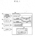
- FIG. 1 is a block diagram showing an example of the display system in this embodiment.
- a display system 1 includes a current position detection processing unit 10, a display 20, a speaker 30, a camera 40, and a display device 50.
- the current position detection processing unit 10 is a current position detection unit that detects the current position of a vehicle in which the display system 1 is mounted (hereinafter called a host vehicle). More specifically, the current position detection processing unit 10 includes at least one of a GPS, a geomagnetic sensor, a distance sensor, and a gyro sensor (all not shown) to detect the current position (coordinates) and orientation of the host vehicle according to a known method.
- the display 20 is a display unit that displays an image guided by the display device 50.
- the actual configuration of the display 20 is not particularly limited.
- a flat panel display such as a known liquid crystal display or an organic EL display, may be used as the display 20.
- the speaker 30 is an output unit that outputs various voices under control of the display device 50.
- the actual mode of voice that is output from the speaker 30 is not particularly limited. For example, a synthetic voice generated as necessary and a prerecorded voice may be output.
- the camera 40 is a shooting unit that shoots the road surface that lies ahead in the traveling direction (hereinafter called a forward road surface) of the host vehicle. Image data shot by the camera 40 is input to a control unit 51 that will be described later.
- the actual configuration of the camera 40 is not particularly limited.
- the camera 40 is configured by a known imaging element such as a CMOS image sensor or a CCD image sensor or by a known optical part such as a lens or a prism.
- the display device 50 a display control unit that controls the display, includes the control unit 51 and a data recording unit 52.
- the control unit 51 is a control unit that controls the display device 50. More specifically, the control unit 51 is a computer configured by a CPU, various programs interpreted for execution on the CPU (including basic control programs such as the OS and application programs started on the OS for executing specific functions), and an internal memory such as a RAM in which programs and various types of data are stored.
- the display program in this embodiment is installed in the display device 50 via any storage medium or a network for effectively configuring the parts of the control unit 51.
- This control unit 51 functionally and conceptually includes an image acquisition unit 51a, an image recognition unit 51 b, a lane structure acquisition unit 51 c, a guide control unit 51d, and a display control unit 51e.
- the image acquisition unit 51a acquires an image imaged by the camera 40.
- the image recognition unit 51b recognizes the lane boundaries by analyzing an image acquired by the image acquisition unit 51a.
- the lane structure acquisition unit 51c acquires the lane structure at a junction that lies ahead on a traveling road.
- the guide control unit 51d determines a recommended lane and a guidance-message output time.
- the display control unit 51e displays an actual scene image on the display 20 and superimposes an arrow object on the display 20.
- the display control unit 51e changes the shape of the arrow object such that the distance of the directional component along the travel lane becomes smaller for at least one of the travel lane part, the crossing part, and the recommended lane part.
- the "lane structure” refers to the physical structure of lanes and includes the number of lanes, the lane type (through lane, right turn lane, left turn lane, etc.), lane shape, and lane positions (positions of lanes in the horizontal direction).
- the "travel lane” refers to a lane in which the host vehicle is currently traveling.
- the “recommended lane” refers to a lane most recommended for the host vehicle to travel from the current position to the destination (hereinafter simply called a "route").
- the "arrow object” is an arrow-shaped object displayed on the display 20 to guide the driver through a route.
- the data recording unit 52 is a recording unit that records therein programs and various types of data required for the operation of the display device 50.
- the data recording unit 52 is configured by a hard disk drive (not shown) used as an external recording device.
- a hard disk drive In place of or in addition to a hard disk drive, a magnetic recording medium such as a magnetic disk, an optical recording medium such as a DVD or a blue ray disc, or any other recording medium may also be used.
- This data recording unit 52 includes a map information database (in the description below, a database is called a DB).
- a map information DB 52a is a map information storage unit that stores map information.
- Map information information required to identify the positions of various points such as an intersection or a stop point, includes intersection data (intersection coordinates), map display data used for displaying a map on the display 20, and so on.
- the map information includes lane structure information.
- the "lane structure information” identifies the lane structure of each road.
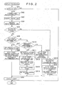
- FIG. 2 is a flowchart showing the display processing (In the following description of processing, "step” is abbreviated as "S").
- This display processing superimposes an arrow object, which guides the driver about a lane change from the travel lane to a recommended lane, on the actual image of the road ahead of the vehicle. For example, this display processing is started automatically after the host vehicle starts traveling and is executed repeatedly at predetermined intervals.
- the display control unit 51e determines whether a route is set (SA1). For example, if the input of a destination has been accepted from a driver according to a known method, the guide control unit 51d sets a route, from the host vehicle's current position acquired by the current position detection processing unit 10 to the destination accepted from the driver, according to a known method such as the Dijkstra's algorithm. If a route is not set, the display control unit 51e determines that a route is not yet set (No in SA1) and terminates the display processing considering that the arrow object need not be superimposed.
- SA1 a route is set
- the display control unit 51e recognizes the lanes in an actual image (SA2). For example, the image acquisition unit 51a acquires an actual image shot by the camera 40, and the image recognition unit 51b analyzes the acquired actual image according to a known method and recognizes the lane boundaries included in the actual image. After that, the display control unit 51e recognizes the lanes divided by the lane boundaries.
- the display control unit 51e identifies the travel lane in the actual image (SA3). For example, the display control unit 51e identifies the position of the lane, which is one of the lanes included in the actual image identified in SA2 and is present in the horizontally central position (front ahead of host vehicle) in the actual image, as the position of the travel lane in the actual image.
- the display control unit 51e identifies a recommended lane in the actual image (SA4).
- SA4 the lane structure acquisition unit 51c identifies, in the map information, the position of the recommended lane relative to the travel lane based on the lane structure information and the route that is found to be set in SA1. Then, the display control unit 51e identifies the position of the recommended lane in the actual image based on the identified relative position in the map information and the position of the travel lane in the actual image identified in SA2.
- the display control unit 51e determines whether the host vehicle is straddling two lanes (SA5). "Straddling two lanes” means that the host vehicle is in the process of changing the lane and now on a lane boundary. For example, the display control unit 51e determines that the host vehicle is straddling two lanes if the position of one of the lane boundaries in the actual image, recognized in SA2, is within a predetermined distance (for example, 1m) left or right from the horizontally central position of the actual image.
- SA5 straddling two lanes
- the display control unit 51e determines whether the host vehicle is traveling in the recommended lane (SA6). For example, if the travel lane identified in SA3 matches the recommended lane identified in SA4, the display control unit 51e determines that the host vehicle is traveling in the recommended lane. If the host vehicle is traveling in the recommended lane in this manner (Yes in SA6), the display control unit 51e determines that the vehicle should travel straight ahead without changing the lanes to allow the host vehicle to travel in the recommended lane. Then, the display control unit 51e sets the display status, which is a status in the guidance display, to "straight ahead" and sets the status in the RAM, not shown, provided in the display device 50 (SA7).
- the display control unit 51e identifies the drawing position of the arrow object (SA8).
- SA8 drawing position of the arrow object
- the arrow object is drawn as a straight line that extends from the end point (The end point is the arrow object's endpoint on the host vehicle side. This term is used in the description below.) to the start point (The start point is the arrow object's endpoint on the host vehicle's traveling direction side. This term is used in the description below.) as shown in the display example in FIG. 3 . Therefore, the drawing position of the arrow object is identified by identifying the coordinates of the start point and the end point.
- the display control unit 51e first identifies the central position of each lane. To do so, the display control unit 51e sets the axis of coordinates (X-axis in horizontal direction and Y-axis in traveling direction) on the display 20 on which the actual image acquired in SA2 is displayed and, at predetermined intervals along the Y-axis, acquires the coordinates of the positions on the lane boundaries, identified in SA2, as shown in the diagram in FIG. 4 .
- the display control unit 51e finds the coordinates of each pair of the neighboring positions at the same position on the Y-axis, calculates the coordinates of the midpoint of the coordinates of the positions forming each pair, and identifies the coordinates of the central positions of each lane and the central vector of each lane configured by joining the coordinates of the central positions.
- the origin of the X-Y coordinates is set in the lower-left corner of the display 20.
- the display control unit 51e identifies the start point of the arrow object. For example, the display control unit 51e acquires the central vector of the lane corresponding to the recommended lane identified in SA4 (that is, the vector of the recommended lane) from the central vectors of the identified lanes. After that, the display control unit 51e determines the coordinates of the intersection between the vector of the recommended lane and a horizontal line, which is set at the first default height (corresponding to default Y-coordinate), as the coordinates of the start point of the arrow object.
- the first default height may be set to another height according to the lane structure such as the shape of a lane curve, whether or not there is merging into or exiting from the lane.
- the display control unit 51e displays the lanes (SA9). That is, as shown in the display example in FIG. 3 , the display control unit 51e superimposes a straight arrow object determined in SA8, which extends from the end point to the start point, on the actual image recognized in SA2 and then displays the image on the display 20. After displaying the image, the display control unit 51e terminates the display processing.
- the display control unit 51e determines whether the remaining distance from the vehicle's current position to the junction is smaller than a predetermined distance (for example, 300m) (SA10). For example, to determine whether the remaining distance is smaller than the predetermined distance, the display control unit 51e first calculates the remaining distance based on the following two positions: vehicle's current position at that time identified by the current position detection processing unit 10 using a known method, and the position of the junction acquired from the map information DB 52a of the data recording unit 52. Then, the display control unit 51e compares the calculated remaining distance with a predetermined distance pre-set in the data recording unit 52.
- a predetermined distance for example, 300m
- the display control unit 51e determines that the host vehicle should change the lane from the travel lane to the recommended lane to allow the host vehicle to travel in the recommended lane. To notify the driver to change the lane, the display control unit 51e sets the display status, which is the guidance display status, to "change lane” and sets the status in the RAM, not shown, provided in the display device 50 (SA11).
- the display control unit 51e identifies the drawing position of the arrow object (SA12). If the display status is "change lane" (or if the display status is "straddling lanes” as will be described later), the arrow object is drawn as shown in the display example in FIG. 5 as a concatenation of the following three: the straight line in the recommended lane (hereinafter called the recommended lane part), the straight line in the travel lane (hereinafter called the travel lane part), and the straight line from the travel lane to the recommended lane (hereinafter called the crossing part). To draw the arrow object in this way, the display control unit 51e identifies the drawing position of the arrow object in SA12 by identifying the following coordinates as shown in the diagram in FIG.
- the display control unit 51e identifies, as in SA8 , the central position of the lanes and identifies the coordinates of the start point of the arrow object by determining the coordinates of the intersection between the vector of the recommended lane and the horizontal line setting at the first default height.
- the display control unit 51e sets the end point of the arrow object in a way different from that in SA8. That is, the display control unit 51e sets the end point of the arrow object based on the central vector of the travel lane identified in SA3 (setting of host vehicle central position). More specifically, the display control unit 51e acquires the central vector of the lane corresponding to the travel lane identified in SA3 (that is, the vector of the travel lane) from the central vectors of the identified lanes.
- the display control unit 51e sets the first change point (SA13). For example, the display control unit 51e identifies the coordinates, which indicate a point on the vector of the recommended lane acquired in the same manner as in SA8 and which indicate a point located a predetermined distance from the start point (that is, the distance of the recommended lane part is a predetermined distance), as the coordinates of the first change point.
- the standard distance of this recommended lane part may be determined by any method. For example, to increase the visibility of the recommended lane, it is preferable that the ratio of the standard distance of the recommended lane part to the whole distance of the arrow object be higher to some extent. To satisfy this requirement, the standard distance of the recommended lane part is determined in advance as a fixed value (for example, 30 m) so that the ratio is a predetermined ratio (for example, 40%). The determined value is recorded in the data recording unit 52.
- the display control unit 51e sets the second change point (SA14). For example, the display control unit 51e identifies the coordinates of the second change point so that the angle ⁇ between the straight line, which joins the first change point and the second change point, and the lane boundary on the recommended lane side of the travel lane is a predetermined angle.
- This predetermined angle may be determined by any method. For example, to allow the driver to easily identify between the arrow object and a lane boundary, the predetermined angle should be larger to some extent. For example, the predetermined angle ⁇ is set to 60°.
- the display control unit 51e displays the lanes (SA9). That is, with the arrow object superimposed on the actual image identified in SA2, the display control unit 51e displays the image on the display 20.
- This arrow object is configured by the recommended lane part extending from the start point to the first change point, the crossing part extending from the first change point to the second change point, and the travel lane part extending from the second change point to the end point, wherein the start point, end point, first change point, and second change point are determined in SA12 - SA14.
- FIG. 7 is a flowchart showing the lane change prompting representation drawing processing. This processing is drawing processing to prompt a driver to change the lane from a travel lane to a recommended lane as soon as possible.
- the display control unit 51e identifies the coordinates of the central positions of the lanes and the coordinates of the start point and the end point of the arrow object (SB1).
- the display control unit 51e identifies the coordinates of the central positions of the lanes and the start point and the end point of the arrow object in the same manner as in SA12.
- the display control unit 51e sets the first change point. To do so, the display control unit 51e first calculates the distance of the recommended lane part according to the expression given below (SB2). After that, the display control unit 51e sets a point, which is on the central vector of the recommended lane and is away from the start point, identified in SB1, toward the host vehicle side by the calculated distance of the recommended lane part, as the first change point (SB3).
- M T + t / L
- M the distance of the recommended lane part
- T is the standard distance of recommended lane part
- t is a constant satisfying t >
- L is the remaining distance.
- the crossing part of the arrow object is drawn as an oblique line that returns, in front of the vehicle, from a point far from the vehicle to a point near the vehicle.
- This representation is not preferable because it does not visually match the image that a vehicle is traveling forward.
- the minimum value of L be set to a fixed value (for example, 1 m) in the expression above and that, if the actual remaining distance is smaller than 1, the value of L remain set to the fixed value (for example, remain set to 1 m) to prevent the distance of the recommended lane part from being too large.
- the maximum value of the distance of the recommended lane part is set to a value that satisfies the condition "the Y-coordinate of the first change point is equal to the Y-coordinate of the second change point". It is preferable that the constant t be set to a value so that the maximum value of the distance of the recommended lane part satisfying the above-described condition is "T + t".
- the display control unit 51e After calculating the distance of the recommended lane part as described above, the display control unit 51e sets a point, which is on the central vector of the recommended lane and is away from the start point, identified in SB1, toward the host vehicle side by the calculated distance of the recommended lane part, as the first change point (SB3). After that, the display control unit 51e sets the second change point in the same manner as in SA14 (SB4) and terminates the lane change prompting representation drawing processing. After that, control returns to the display processing in FIG. 2 , where the display control unit 51e displays the lanes (SA9). After displaying the lanes, the display control unit 51e terminates the display processing.
- FIG. 8 is a diagram showing a display example of the superimposed display of the arrow object on the actual image.
- the comparison between the display example in FIG. 8 and the display example in FIG. 5 indicates that the shape of the arrow object is changed in at least one of the travel lane part, the crossing part, and the recommended lane part such that the distance of the directional component along the travel lane (distance of the component along the central vector of the travel lane) is shortened. More specifically, though the recommended lane part becomes larger as the remaining distance becomes smaller, the coordinates of the start point and the coordinates of the end point remain the same in this embodiment regardless of the remaining distance. This results in that the total distance of the directional components along the travel lane for the travel lane part and the crossing part becomes smaller.
- the total distance of the directional components along the travel lane for the travel lane part, the crossing part, and the recommended lane part does not change but remains the constant distance.
- Setting the first change point in this manner causes the first change point to move toward the vehicle's current position along the central vector of the recommended lane in which the first change point is present.
- the display processing if repeated in the same manner until the host vehicle arrives at the destination, causes the lane change prompting representation drawing processing to be repeated if the travel lane is not the recommended lane and the remaining distance is equal to or smaller than a predetermined distance.
- the first change point gradually moves toward the vehicle's current position along the central vector of the recommended lane with the result that the recommended lane part gradually becomes larger.
- This display processing gives a driver a visual impression that the arrow object is approaching the host vehicle and allows the driver to intuitively understand that the vehicle is approaching the junction, thus prompting the driver to change the lane.
- the display control unit 51e sets the display status to "straddling lanes” and sets the status in the RAM, not shown, provided in the display device 50 (SA16).
- the display control unit 51e identifies the drawing position of the arrow object.
- the arrow object is drawn as a straight line extending from the end point to the start point.
- the display control unit 51e identifies the drawing position of the arrow object by identifying the coordinates of the start point and the coordinates of the end point.
- the display control unit 51e identifies those coordinates as in SA12.
- the tip of the arrow object may be drawn as the recommended lane part, extending from the start point to the first change point, as in SA9.
- the display control unit 51e terminates the display processing.
- the shape of the arrow object is changed such that, as the remaining distance from the vehicle's current position to the junction becomes smaller, the distance of the directional component along the travel lane is shortened for at least one of the travel lane part, the crossing part, and the recommended lane part. Therefore, as the remaining distance becomes smaller, the arrow object is displayed such that the travel lane part, the crossing part, or the recommended lane part becomes smaller.
- This display processing gives a driver a visual impression that the arrow object is approaching the host vehicle and allows the driver to intuitively understand that the vehicle is approaching the junction, thus prompting the driver to change the lane.
- the shape of the arrow object is changed such that, as the remaining distance becomes smaller, the distance of the directional component along the travel lane is shortened for the travel lane part and the crossing part. Therefore, as the remaining distance becomes smaller, this display processing gives a driver a visual impression that the arrow object is approaching the host vehicle and allows the driver to intuitively understand that the vehicle is approaching the junction, thus prompting the driver to change the lane.
- the shape of the arrow object is changed such that, even if the remaining distance becomes smaller, the total distance of the directional components along the travel lane for the travel lane part, the crossing part, and the recommended lane part does not change. Therefore, as the remaining distance becomes smaller, this display processing displays the arrow object such that, the travel lane part or the crossing part becomes smaller and, in addition, the recommended lane part becomes larger, thereby allowing a driver to more intuitively understand that the vehicle is approaching the junction.
- the shape of the arrow object is changed such that, as the remaining distance becomes smaller, at least one of the start point, the first change point, and the second change point moves toward the vehicle's current position. Therefore, as the remaining distance becomes smaller, this display processing gradually makes the whole arrow smaller and changes the intersection angle between the lane boundary and the crossing part, thereby allowing a driver to more intuitively understand that the vehicle is approaching the junction.
- the problems to be solved by the invention and the effect of the invention are not limited to those described above but may vary according to the implementation environment of the invention or the detail of the configuration.
- the invention solves only a part of the problems described above or achieves only a part of the effect described above. For example, even if a driver may not intuitively understand that the host vehicle approaches a junction but if the driver can understand more easily, or can understand to the same extent as before via a technology different from conventional technologies, that the host vehicle approaches a junction, the problem of the present invention is solved.
- the electrical components described above are functional and conceptual components that need not be always be configured physically as shown in the figures. That is, a specific mode of the distribution or integration of the units is not limited to that shown in the figures. Instead, the whole or a part of the units may be distributed or integrated functionally or physically in any number of units according to the various loads or the usage status.
- the components of the display system 1, which are distributed may be interconnected via a network.
- the travel lane part or the crossing part is drawn in the lane change prompting representation drawing processing such that the distance of the directional component along the travel lane is small.
- the recommended lane part may also be drawn such that the distance of its directional component along the travel lane part is small.
- the shape of the arrow object is changed such that, even if the remaining distance becomes smaller, the total distance of the directional components along the travel lane for the travel lane part, the crossing part, and the recommended lane part is not changed. Instead of this, the shape of the arrow object may also be changed such that the total distance is changed.
- the shape of the arrow object is changed such that the first change point moves in the direction toward the vehicle's current position along the central vector of the recommended lane in which the first change point is present.
- the shape of the arrow object may also be changed such that the second change point moves in the direction toward the vehicle's current position along the central vector of the travel lane in which the second change point is present.
Landscapes
- Engineering & Computer Science (AREA)
- Radar, Positioning & Navigation (AREA)
- Remote Sensing (AREA)
- Physics & Mathematics (AREA)
- General Physics & Mathematics (AREA)
- Automation & Control Theory (AREA)
- Navigation (AREA)
- Traffic Control Systems (AREA)
- Instructional Devices (AREA)
Abstract
Description
- The disclosure of Japanese Patent Application No.
2011-272829 filed on December 13, 2011 - The present invention relates to a display system, a display method, and a display program.
- As one of the technologies for use in an in-vehicle navigation device for guiding a driver to a destination, the following navigation device is proposed. When a driver is required at a junction to change the lane in order to travel in the direction to a destination, the navigation device creates a lane-changing guide graphic based on the data on the detected shape of the road ahead of the current position and superimposes the created guide graphic on the image of the road ahead of the vehicle. In this case, if the driver does not change the lane even after the guide graphic is displayed, the tip of the guide graphic extends in the direction to the destination to prompt the driver to change the lane (for example, paragraph 0032 and FIG. 11 in Japanese Patent Application Publication No.
10-281795 JP 10-281795 A - However, if a driver does not change the lane even after a guide graphic is displayed, the navigation device in the related art described above simply extends the tip of the guide graphic in the direction to a destination. Therefore, with this navigation device, the driver cannot intuitively understand that the vehicle is approaching a junction. This means that the navigation device cannot appropriately prompt the driver to change the lane.
- In view of the foregoing, it is an object of the present invention to provide a display system, a display method, and a display program that make it easy for a driver to intuitively understand that the vehicle is approaching a junction.
- In a display system according to a first aspect, a display method according to a fifth aspect, and a display program according to a sixth aspect, the shape of an arrow object is changed such that, as the remaining distance from a vehicle's current position to a junction becomes smaller, the distance of a directional component along a travel lane is shortened for at least one of a travel lane part, a crossing part, and a recommended lane part. Therefore, as the remaining distance becomes smaller, the arrow object is displayed such that the travel lane part, the crossing part, or the recommended lane part becomes smaller. This display processing gives a driver a visual impression that the arrow object is approaching the host vehicle and allows the driver to intuitively understand that the vehicle is approaching the junction, thus prompting the driver to change the lane.
- In a display system according to a second aspect, the shape of the arrow object is changed such that, as the remaining distance becomes smaller, the distance of directional components along the travel lane is shortened for the travel lane part and the crossing part. Therefore, as the remaining distance becomes smaller, this display processing gives a driver a visual impression that the arrow object is approaching the host vehicle and allows the driver to intuitively understand that the vehicle is approaching the junction, thus prompting the driver to change the lane.
- In a display system according to a third aspect, the shape of the arrow object is changed such that, even if the remaining distance becomes smaller, the total distance of directional components along the travel lane for the travel lane part, the crossing part, and the recommended lane part does not change. Therefore, as the remaining distance becomes smaller, this display processing displays the arrow object such that, the travel lane part or the crossing part becomes smaller and, in addition, the recommended lane part becomes larger, thereby allowing a driver to more intuitively understand that the vehicle is approaching the junction.
- In a display system according to a fourth aspect, the shape of the arrow object is changed such that, as the remaining distance becomes smaller, at least one of the start point, the first change point, and the second change point moves toward the vehicle's current position. Therefore, as the remaining distance becomes smaller, this display processing gradually makes the whole arrow smaller and changes the intersection angle between a lane boundary and the crossing part, thereby allowing a driver to more intuitively understand that the vehicle is approaching the junction.
-
-
FIG. 1 is a block diagram showing an example of a display system in an embodiment of the present invention; -
FIG. 2 is a flowchart showing the display processing; -
FIG. 3 is a diagram showing a display example of a route guidance arrow; -
FIG. 4 is a diagram showing the concept of the drawing processing; -
FIG. 5 is a diagram showing a display example of a route guidance arrow; -
FIG. 6 is a diagram showing the concept of the drawing processing; -
FIG. 7 is a flowchart showing the lane change prompting representation drawing processing; and -
FIG. 8 is a diagram showing a display example of the route guidance arrow after the lane change prompting representation drawing processing. - Embodiments of a display system, a display method, and a display program of the present invention will now be described below in detail with reference to the drawings. It should be noted that the present invention is not limited by the embodiments.
- First, the following describes a configuration of a display system in this embodiment.
FIG. 1 is a block diagram showing an example of the display system in this embodiment. As shown inFIG. 1 , adisplay system 1 includes a current positiondetection processing unit 10, adisplay 20, aspeaker 30, acamera 40, and adisplay device 50. - The current position
detection processing unit 10 is a current position detection unit that detects the current position of a vehicle in which thedisplay system 1 is mounted (hereinafter called a host vehicle). More specifically, the current positiondetection processing unit 10 includes at least one of a GPS, a geomagnetic sensor, a distance sensor, and a gyro sensor (all not shown) to detect the current position (coordinates) and orientation of the host vehicle according to a known method. - The
display 20 is a display unit that displays an image guided by thedisplay device 50. The actual configuration of thedisplay 20 is not particularly limited. For example, a flat panel display, such as a known liquid crystal display or an organic EL display, may be used as thedisplay 20. - The
speaker 30 is an output unit that outputs various voices under control of thedisplay device 50. The actual mode of voice that is output from thespeaker 30 is not particularly limited. For example, a synthetic voice generated as necessary and a prerecorded voice may be output. - The
camera 40 is a shooting unit that shoots the road surface that lies ahead in the traveling direction (hereinafter called a forward road surface) of the host vehicle. Image data shot by thecamera 40 is input to acontrol unit 51 that will be described later. The actual configuration of thecamera 40 is not particularly limited. For example, thecamera 40 is configured by a known imaging element such as a CMOS image sensor or a CCD image sensor or by a known optical part such as a lens or a prism. - The
display device 50, a display control unit that controls the display, includes thecontrol unit 51 and adata recording unit 52. - The
control unit 51 is a control unit that controls thedisplay device 50. More specifically, thecontrol unit 51 is a computer configured by a CPU, various programs interpreted for execution on the CPU (including basic control programs such as the OS and application programs started on the OS for executing specific functions), and an internal memory such as a RAM in which programs and various types of data are stored. In particular, the display program in this embodiment is installed in thedisplay device 50 via any storage medium or a network for effectively configuring the parts of thecontrol unit 51. - This
control unit 51 functionally and conceptually includes animage acquisition unit 51a, animage recognition unit 51 b, a lanestructure acquisition unit 51 c, aguide control unit 51d, and adisplay control unit 51e. Theimage acquisition unit 51a acquires an image imaged by thecamera 40. Theimage recognition unit 51b recognizes the lane boundaries by analyzing an image acquired by theimage acquisition unit 51a. The lanestructure acquisition unit 51c acquires the lane structure at a junction that lies ahead on a traveling road. Theguide control unit 51d determines a recommended lane and a guidance-message output time. Thedisplay control unit 51e displays an actual scene image on thedisplay 20 and superimposes an arrow object on thedisplay 20. In addition, as the remaining distance from the vehicle's current position to a junction becomes smaller, thedisplay control unit 51e changes the shape of the arrow object such that the distance of the directional component along the travel lane becomes smaller for at least one of the travel lane part, the crossing part, and the recommended lane part. - In this embodiment, the "lane structure" refers to the physical structure of lanes and includes the number of lanes, the lane type (through lane, right turn lane, left turn lane, etc.), lane shape, and lane positions (positions of lanes in the horizontal direction). The "travel lane" refers to a lane in which the host vehicle is currently traveling. The "recommended lane" refers to a lane most recommended for the host vehicle to travel from the current position to the destination (hereinafter simply called a "route"). For example, if there is a road (lane) on which the host vehicle is to travel after passing through a road junction located ahead of the host vehicle and if the vehicle must travel in a particular lane before passing through the junction in order to enter this road, this particular lane is the recommended lane. The "arrow object" is an arrow-shaped object displayed on the
display 20 to guide the driver through a route. - The
data recording unit 52 is a recording unit that records therein programs and various types of data required for the operation of thedisplay device 50. For example, thedata recording unit 52 is configured by a hard disk drive (not shown) used as an external recording device. In place of or in addition to a hard disk drive, a magnetic recording medium such as a magnetic disk, an optical recording medium such as a DVD or a blue ray disc, or any other recording medium may also be used. - This
data recording unit 52 includes a map information database (in the description below, a database is called a DB). Amap information DB 52a is a map information storage unit that stores map information. "Map information", information required to identify the positions of various points such as an intersection or a stop point, includes intersection data (intersection coordinates), map display data used for displaying a map on thedisplay 20, and so on. The map information includes lane structure information. The "lane structure information" identifies the lane structure of each road. - Next, the following describes the display processing executed by the
display system 1 configured as described above.FIG. 2 is a flowchart showing the display processing (In the following description of processing, "step" is abbreviated as "S"). This display processing superimposes an arrow object, which guides the driver about a lane change from the travel lane to a recommended lane, on the actual image of the road ahead of the vehicle. For example, this display processing is started automatically after the host vehicle starts traveling and is executed repeatedly at predetermined intervals. - First, the
display control unit 51e determines whether a route is set (SA1). For example, if the input of a destination has been accepted from a driver according to a known method, theguide control unit 51d sets a route, from the host vehicle's current position acquired by the current positiondetection processing unit 10 to the destination accepted from the driver, according to a known method such as the Dijkstra's algorithm. If a route is not set, thedisplay control unit 51e determines that a route is not yet set (No in SA1) and terminates the display processing considering that the arrow object need not be superimposed. - On the other hand, if a route is set (Yes in SA1), the
display control unit 51e recognizes the lanes in an actual image (SA2). For example, theimage acquisition unit 51a acquires an actual image shot by thecamera 40, and theimage recognition unit 51b analyzes the acquired actual image according to a known method and recognizes the lane boundaries included in the actual image. After that, thedisplay control unit 51e recognizes the lanes divided by the lane boundaries. - Next, the
display control unit 51e identifies the travel lane in the actual image (SA3). For example, thedisplay control unit 51e identifies the position of the lane, which is one of the lanes included in the actual image identified in SA2 and is present in the horizontally central position (front ahead of host vehicle) in the actual image, as the position of the travel lane in the actual image. - The
display control unit 51e identifies a recommended lane in the actual image (SA4). For example, the lanestructure acquisition unit 51c identifies, in the map information, the position of the recommended lane relative to the travel lane based on the lane structure information and the route that is found to be set in SA1. Then, thedisplay control unit 51e identifies the position of the recommended lane in the actual image based on the identified relative position in the map information and the position of the travel lane in the actual image identified in SA2. - After that, the
display control unit 51e determines whether the host vehicle is straddling two lanes (SA5). "Straddling two lanes" means that the host vehicle is in the process of changing the lane and now on a lane boundary. For example, thedisplay control unit 51e determines that the host vehicle is straddling two lanes if the position of one of the lane boundaries in the actual image, recognized in SA2, is within a predetermined distance (for example, 1m) left or right from the horizontally central position of the actual image. - If the host vehicle is not straddling lanes in SA5 (No in SA5), the
display control unit 51e determines whether the host vehicle is traveling in the recommended lane (SA6). For example, if the travel lane identified in SA3 matches the recommended lane identified in SA4, thedisplay control unit 51e determines that the host vehicle is traveling in the recommended lane. If the host vehicle is traveling in the recommended lane in this manner (Yes in SA6), thedisplay control unit 51e determines that the vehicle should travel straight ahead without changing the lanes to allow the host vehicle to travel in the recommended lane. Then, thedisplay control unit 51e sets the display status, which is a status in the guidance display, to "straight ahead" and sets the status in the RAM, not shown, provided in the display device 50 (SA7). - Next, the
display control unit 51e identifies the drawing position of the arrow object (SA8). When the display status is "straight ahead", the arrow object is drawn as a straight line that extends from the end point (The end point is the arrow object's endpoint on the host vehicle side. This term is used in the description below.) to the start point (The start point is the arrow object's endpoint on the host vehicle's traveling direction side. This term is used in the description below.) as shown in the display example inFIG. 3 . Therefore, the drawing position of the arrow object is identified by identifying the coordinates of the start point and the end point. - For example, the
display control unit 51e first identifies the central position of each lane. To do so, thedisplay control unit 51e sets the axis of coordinates (X-axis in horizontal direction and Y-axis in traveling direction) on thedisplay 20 on which the actual image acquired in SA2 is displayed and, at predetermined intervals along the Y-axis, acquires the coordinates of the positions on the lane boundaries, identified in SA2, as shown in the diagram inFIG. 4 . After that, for the positions on the boundaries, thedisplay control unit 51e finds the coordinates of each pair of the neighboring positions at the same position on the Y-axis, calculates the coordinates of the midpoint of the coordinates of the positions forming each pair, and identifies the coordinates of the central positions of each lane and the central vector of each lane configured by joining the coordinates of the central positions. In the example below, the origin of the X-Y coordinates is set in the lower-left corner of thedisplay 20. - Next, the
display control unit 51e identifies the start point of the arrow object. For example, thedisplay control unit 51e acquires the central vector of the lane corresponding to the recommended lane identified in SA4 (that is, the vector of the recommended lane) from the central vectors of the identified lanes. After that, thedisplay control unit 51e determines the coordinates of the intersection between the vector of the recommended lane and a horizontal line, which is set at the first default height (corresponding to default Y-coordinate), as the coordinates of the start point of the arrow object. The first default height may be set to another height according to the lane structure such as the shape of a lane curve, whether or not there is merging into or exiting from the lane. - The
display control unit 51e also identifies the end point of the arrow object. For example, thedisplay control unit 51e sets the end point of the arrow object based on the central vector of the recommended lane identified in SA4 (setting of recommended lane central position). More specifically, as with the start point of the arrow object described above, thedisplay control unit 51e acquires the central vector of the lane, corresponding to the recommended lane identified in SA4 (that is, the vector of the recommended lane), from the central vectors of the identified lanes. After that, thedisplay control unit 51e determines the coordinates of the intersection between the vector of the recommended lane and a horizontal line, which is set at the second default height (default Y-coordinate), as the coordinates of the end point of the arrow object. Note that thedisplay control unit 51e sets the bottom line of the display 20 (horizontal line with Y-coordinate = 0) as the second default height. - After that, the
display control unit 51e displays the lanes (SA9). That is, as shown in the display example inFIG. 3 , thedisplay control unit 51e superimposes a straight arrow object determined in SA8, which extends from the end point to the start point, on the actual image recognized in SA2 and then displays the image on thedisplay 20. After displaying the image, thedisplay control unit 51e terminates the display processing. - On the other hand, if it is determined in SA6 that the host vehicle is not traveling in the recommended lane (No in SA6), the
display control unit 51e determines whether the remaining distance from the vehicle's current position to the junction is smaller than a predetermined distance (for example, 300m) (SA10). For example, to determine whether the remaining distance is smaller than the predetermined distance, thedisplay control unit 51e first calculates the remaining distance based on the following two positions: vehicle's current position at that time identified by the current positiondetection processing unit 10 using a known method, and the position of the junction acquired from themap information DB 52a of thedata recording unit 52. Then, thedisplay control unit 51e compares the calculated remaining distance with a predetermined distance pre-set in thedata recording unit 52. If the remaining distance is not smaller than the predetermined distance (No in SA10), thedisplay control unit 51e determines that the host vehicle should change the lane from the travel lane to the recommended lane to allow the host vehicle to travel in the recommended lane. To notify the driver to change the lane, thedisplay control unit 51e sets the display status, which is the guidance display status, to "change lane" and sets the status in the RAM, not shown, provided in the display device 50 (SA11). - Next, the
display control unit 51e identifies the drawing position of the arrow object (SA12). If the display status is "change lane" (or if the display status is "straddling lanes" as will be described later), the arrow object is drawn as shown in the display example inFIG. 5 as a concatenation of the following three: the straight line in the recommended lane (hereinafter called the recommended lane part), the straight line in the travel lane (hereinafter called the travel lane part), and the straight line from the travel lane to the recommended lane (hereinafter called the crossing part). To draw the arrow object in this way, thedisplay control unit 51e identifies the drawing position of the arrow object in SA12 by identifying the following coordinates as shown in the diagram inFIG. 6 : the coordinates of the start point and the end point, the coordinates of the intersection between the crossing part and the recommended lane part (hereinafter called a first change point), and the coordinates of the intersection between the travel lane part and the crossing part (hereinafter called a second change point). - For example, the
display control unit 51e identifies, as in SA8 , the central position of the lanes and identifies the coordinates of the start point of the arrow object by determining the coordinates of the intersection between the vector of the recommended lane and the horizontal line setting at the first default height. Thedisplay control unit 51e sets the end point of the arrow object in a way different from that in SA8. That is, thedisplay control unit 51e sets the end point of the arrow object based on the central vector of the travel lane identified in SA3 (setting of host vehicle central position). More specifically, thedisplay control unit 51e acquires the central vector of the lane corresponding to the travel lane identified in SA3 (that is, the vector of the travel lane) from the central vectors of the identified lanes. After that, thedisplay control unit 51e e determines the coordinates of the intersection between the vector of the travel lane and the horizontal line, which is set at the second default height (default Y-coordinate), as the coordinates of the end point of the arrow object. Note that thedisplay control unit 51e sets the bottom line of the display 20 (horizontal line with Y-coordinate = 0) as the second default height. - Next, the
display control unit 51e sets the first change point (SA13). For example, thedisplay control unit 51e identifies the coordinates, which indicate a point on the vector of the recommended lane acquired in the same manner as in SA8 and which indicate a point located a predetermined distance from the start point (that is, the distance of the recommended lane part is a predetermined distance), as the coordinates of the first change point. The standard distance of this recommended lane part may be determined by any method. For example, to increase the visibility of the recommended lane, it is preferable that the ratio of the standard distance of the recommended lane part to the whole distance of the arrow object be higher to some extent. To satisfy this requirement, the standard distance of the recommended lane part is determined in advance as a fixed value (for example, 30 m) so that the ratio is a predetermined ratio (for example, 40%). The determined value is recorded in thedata recording unit 52. - Next, the
display control unit 51e sets the second change point (SA14). For example, thedisplay control unit 51e identifies the coordinates of the second change point so that the angle θ between the straight line, which joins the first change point and the second change point, and the lane boundary on the recommended lane side of the travel lane is a predetermined angle. This predetermined angle may be determined by any method. For example, to allow the driver to easily identify between the arrow object and a lane boundary, the predetermined angle should be larger to some extent. For example, the predetermined angle θ is set to 60°. - After that, the
display control unit 51e displays the lanes (SA9). That is, with the arrow object superimposed on the actual image identified in SA2, thedisplay control unit 51e displays the image on thedisplay 20. This arrow object is configured by the recommended lane part extending from the start point to the first change point, the crossing part extending from the first change point to the second change point, and the travel lane part extending from the second change point to the end point, wherein the start point, end point, first change point, and second change point are determined in SA12 - SA14. After displaying the lanes as described above, thedisplay control unit 51e terminates the display processing. - On the other hand, if the remaining distance from the vehicle's current position to the junction is smaller than a predetermined distance in SA10 (Yes in SA10), the lane change prompting representation drawing processing is started.
FIG. 7 is a flowchart showing the lane change prompting representation drawing processing. This processing is drawing processing to prompt a driver to change the lane from a travel lane to a recommended lane as soon as possible. - First, the
display control unit 51e identifies the coordinates of the central positions of the lanes and the coordinates of the start point and the end point of the arrow object (SB1). Thedisplay control unit 51e identifies the coordinates of the central positions of the lanes and the start point and the end point of the arrow object in the same manner as in SA12. - Next, the
display control unit 51e sets the first change point. To do so, thedisplay control unit 51e first calculates the distance of the recommended lane part according to the expression given below (SB2). After that, thedisplay control unit 51e sets a point, which is on the central vector of the recommended lane and is away from the start point, identified in SB1, toward the host vehicle side by the calculated distance of the recommended lane part, as the first change point (SB3).
where M is the distance of the recommended lane part,
T is the standard distance of recommended lane part,
t is a constant satisfying t > 0, and
L is the remaining distance. - If the Y-coordinate of the first change point that is set according to the expression above is smaller than the Y-coordinate of the second change point, the crossing part of the arrow object is drawn as an oblique line that returns, in front of the vehicle, from a point far from the vehicle to a point near the vehicle. This representation is not preferable because it does not visually match the image that a vehicle is traveling forward. To prevent this situation, it is preferable that the minimum value of L be set to a fixed value (for example, 1 m) in the expression above and that, if the actual remaining distance is smaller than 1, the value of L remain set to the fixed value (for example, remain set to 1 m) to prevent the distance of the recommended lane part from being too large. The maximum value of the distance of the recommended lane part is set to a value that satisfies the condition "the Y-coordinate of the first change point is equal to the Y-coordinate of the second change point". It is preferable that the constant t be set to a value so that the maximum value of the distance of the recommended lane part satisfying the above-described condition is "T + t".
- After calculating the distance of the recommended lane part as described above, the
display control unit 51e sets a point, which is on the central vector of the recommended lane and is away from the start point, identified in SB1, toward the host vehicle side by the calculated distance of the recommended lane part, as the first change point (SB3). After that, thedisplay control unit 51e sets the second change point in the same manner as in SA14 (SB4) and terminates the lane change prompting representation drawing processing. After that, control returns to the display processing inFIG. 2 , where thedisplay control unit 51e displays the lanes (SA9). After displaying the lanes, thedisplay control unit 51e terminates the display processing. -
FIG. 8 is a diagram showing a display example of the superimposed display of the arrow object on the actual image. The comparison between the display example inFIG. 8 and the display example inFIG. 5 indicates that the shape of the arrow object is changed in at least one of the travel lane part, the crossing part, and the recommended lane part such that the distance of the directional component along the travel lane (distance of the component along the central vector of the travel lane) is shortened. More specifically, though the recommended lane part becomes larger as the remaining distance becomes smaller, the coordinates of the start point and the coordinates of the end point remain the same in this embodiment regardless of the remaining distance. This results in that the total distance of the directional components along the travel lane for the travel lane part and the crossing part becomes smaller. Because the coordinates of the start point and the coordinates of the end point remain the same regardless of the remaining distance just as described, the total distance of the directional components along the travel lane for the travel lane part, the crossing part, and the recommended lane part does not change but remains the constant distance. Setting the first change point in this manner causes the first change point to move toward the vehicle's current position along the central vector of the recommended lane in which the first change point is present. The display processing, if repeated in the same manner until the host vehicle arrives at the destination, causes the lane change prompting representation drawing processing to be repeated if the travel lane is not the recommended lane and the remaining distance is equal to or smaller than a predetermined distance. In this manner, the first change point gradually moves toward the vehicle's current position along the central vector of the recommended lane with the result that the recommended lane part gradually becomes larger. This display processing gives a driver a visual impression that the arrow object is approaching the host vehicle and allows the driver to intuitively understand that the vehicle is approaching the junction, thus prompting the driver to change the lane. - On the other hand, if the host vehicle is straddling lanes in SA5 in
FIG. 2 (Yes in SA5), thedisplay control unit 51e sets the display status to "straddling lanes" and sets the status in the RAM, not shown, provided in the display device 50 (SA16). - Next, the
display control unit 51e identifies the drawing position of the arrow object. When the display status indicates "straddling lanes", the arrow object is drawn as a straight line extending from the end point to the start point. To draw this straight line, thedisplay control unit 51e identifies the drawing position of the arrow object by identifying the coordinates of the start point and the coordinates of the end point. Thedisplay control unit 51e identifies those coordinates as in SA12. In this case, the tip of the arrow object may be drawn as the recommended lane part, extending from the start point to the first change point, as in SA9. After that, thedisplay control unit 51e terminates the display processing. - According to this embodiment, the shape of the arrow object is changed such that, as the remaining distance from the vehicle's current position to the junction becomes smaller, the distance of the directional component along the travel lane is shortened for at least one of the travel lane part, the crossing part, and the recommended lane part. Therefore, as the remaining distance becomes smaller, the arrow object is displayed such that the travel lane part, the crossing part, or the recommended lane part becomes smaller. This display processing gives a driver a visual impression that the arrow object is approaching the host vehicle and allows the driver to intuitively understand that the vehicle is approaching the junction, thus prompting the driver to change the lane.
- The shape of the arrow object is changed such that, as the remaining distance becomes smaller, the distance of the directional component along the travel lane is shortened for the travel lane part and the crossing part. Therefore, as the remaining distance becomes smaller, this display processing gives a driver a visual impression that the arrow object is approaching the host vehicle and allows the driver to intuitively understand that the vehicle is approaching the junction, thus prompting the driver to change the lane.
- The shape of the arrow object is changed such that, even if the remaining distance becomes smaller, the total distance of the directional components along the travel lane for the travel lane part, the crossing part, and the recommended lane part does not change. Therefore, as the remaining distance becomes smaller, this display processing displays the arrow object such that, the travel lane part or the crossing part becomes smaller and, in addition, the recommended lane part becomes larger, thereby allowing a driver to more intuitively understand that the vehicle is approaching the junction.
- The shape of the arrow object is changed such that, as the remaining distance becomes smaller, at least one of the start point, the first change point, and the second change point moves toward the vehicle's current position. Therefore, as the remaining distance becomes smaller, this display processing gradually makes the whole arrow smaller and changes the intersection angle between the lane boundary and the crossing part, thereby allowing a driver to more intuitively understand that the vehicle is approaching the junction.
- While the embodiment of the present invention has been described, specific configurations and units of the present invention may be altered and modified in any way within the scope of the technical concept of the invention described in the claims. The following describes those modifications.
- First, the problems to be solved by the invention and the effect of the invention are not limited to those described above but may vary according to the implementation environment of the invention or the detail of the configuration. Sometimes, the invention solves only a part of the problems described above or achieves only a part of the effect described above. For example, even if a driver may not intuitively understand that the host vehicle approaches a junction but if the driver can understand more easily, or can understand to the same extent as before via a technology different from conventional technologies, that the host vehicle approaches a junction, the problem of the present invention is solved.
- It should be noted that the electrical components described above are functional and conceptual components that need not be always be configured physically as shown in the figures. That is, a specific mode of the distribution or integration of the units is not limited to that shown in the figures. Instead, the whole or a part of the units may be distributed or integrated functionally or physically in any number of units according to the various loads or the usage status. For example, the components of the
display system 1, which are distributed, may be interconnected via a network. - In the above embodiment, the travel lane part or the crossing part is drawn in the lane change prompting representation drawing processing such that the distance of the directional component along the travel lane is small. Instead, the recommended lane part may also be drawn such that the distance of its directional component along the travel lane part is small. In the above embodiment, the shape of the arrow object is changed such that, even if the remaining distance becomes smaller, the total distance of the directional components along the travel lane for the travel lane part, the crossing part, and the recommended lane part is not changed. Instead of this, the shape of the arrow object may also be changed such that the total distance is changed. In the embodiment described above, the shape of the arrow object is changed such that the first change point moves in the direction toward the vehicle's current position along the central vector of the recommended lane in which the first change point is present. Instead of this, the shape of the arrow object may also be changed such that the second change point moves in the direction toward the vehicle's current position along the central vector of the travel lane in which the second change point is present.
- It is explicitly stated that all features disclosed in the description and/or the claims are intended to be disclosed separately and independently from each other for the purpose of original disclosure as well as for the purpose of restricting the claimed invention independent of the composition of the features in the embodiments and/or the claims. It is explicitly stated that all value ranges or indications of groups of entities disclose every possible intermediate value or intermediate entity for the purpose of original disclosure as well as for the purpose of restricting the claimed invention, in particular as limits of value ranges.
Claims (9)
- A display system (1) comprising a display control unit (51) for providing a superimposed display of an arrow object on an actual image of a road ahead of a vehicle, the arrow object being provided for guiding a driver about a lane change route for changing a lane from a travel lane to a recommended lane, the travel lane being a lane in which the vehicle is currently traveling, the recommended lane being a lane that allows the vehicle to enter a lane in which the vehicle is to travel after passing through a road junction ahead of the vehicle wherein
the arrow object includes a travel lane part displayed as a superimposed image on the travel lane, a crossing part displayed as a superimposed image traversing from the travel lane to the recommended lane, and a recommended lane part displayed as a superimposed image on the recommended lane, wherein
the display control unit (51) is adapted to change a shape of the arrow object such that, as a remaining distance from a current position of the vehicle to the junction becomes smaller, a distance of a directional component along the travel lane for at least one of the travel lane part, the crossing part, and the recommended lane part is shortened. - The display system (1) according to claim 1 wherein
the display control unit is further adapted to change the shape of the arrow object such that, as the remaining distance becomes smaller, the total distance of directional components along the travel lane for the travel lane part and the crossing part is shortened. - The display system (1) according to claim 1 or 2 wherein
the display control unit is further adapted to change the shape of the arrow object such that, even if the remaining distance becomes smaller, the total distance of directional components along the travel lane for the travel lane part, the crossing part, and the recommended lane part does not change. - The display system (1) according to anyone of claims 1 to 3 wherein
the display control unit is further adapted to change the shape of the arrow object such that, as the remaining distance becomes smaller, at least one of a start point that is a farthest point from the current position of the vehicle in the recommended lane part, a first change point that is an intersection between the crossing part and the recommended lane part, and a second change point that is an intersection between the travel lane part and the crossing part moves closer toward the current position of the vehicle along a central vector of the travel lane or the recommended lane in which each of the points is present. - A display method comprising a step of providing a superimposed display of an arrow object on an actual image of a road ahead of a vehicle, the arrow object being provided for guiding a driver about a lane change route for changing a lane from a travel lane to a recommended lane, the travel lane being a lane in which the vehicle is currently traveling, the recommended lane being a lane that allows the vehicle to enter a lane in which the vehicle is to travel after passing through a road junction ahead of the vehicle wherein
the arrow object includes a travel lane part displayed as a superimposed image on the travel lane, a crossing part displayed as a superimposed image traversing from the travel lane to the recommended lane, and a recommended lane part displayed as a superimposed image on the recommended lane, further comprising a step of
changing a shape of the arrow object such that, as a remaining distance from a current position of the vehicle to the junction becomes smaller, the distance of a directional component along the travel lane for at least one of the travel lane part, the crossing part, and the recommended lane part is shortened. - The display method according to claim 5 wherein in the step of changing the shape of the arrow object the shape of the arrow object is changed such that, as the remaining distance becomes smaller, the total distance of directional components along the travel lane for the travel lane part and the crossing part is shortened.
- The display method according to claim 5 or 6 wherein in the step of changing the shape of the arrow object the shape of the arrow object is changed such that, even if the remaining distance becomes smaller, the total distance of directional components along the travel lane for the travel lane part, the crossing part, and the recommended lane part does not change
- The display method according to anyone of claims 5 to 7 wherein in the step of changing the shape of the arrow object the shape of the arrow object is changed such that, as the remaining distance becomes smaller, at least one of a start point that is a farthest point from the current position of the vehicle in the recommended lane part, a first change point that is an intersection between the crossing part and the recommended lane part, and a second change point that is an intersection between the travel lane part and the crossing part moves closer toward the current position of the vehicle along a central vector of the travel lane or the recommended lane in which each of the points is present.
- A display program that causes when run on a computer, a computer-implemented display system to execute the method steps according to anyone of claims 5 to 8.
Applications Claiming Priority (1)
| Application Number | Priority Date | Filing Date | Title |
|---|---|---|---|
| JP2011272829A JP5724864B2 (en) | 2011-12-13 | 2011-12-13 | Display system, display method, and display program |
Publications (3)
| Publication Number | Publication Date |
|---|---|
| EP2605231A2 true EP2605231A2 (en) | 2013-06-19 |
| EP2605231A3 EP2605231A3 (en) | 2015-06-24 |
| EP2605231B1 EP2605231B1 (en) | 2017-11-08 |
Family
ID=47562988
Family Applications (1)
| Application Number | Title | Priority Date | Filing Date |
|---|---|---|---|
| EP12194857.4A Not-in-force EP2605231B1 (en) | 2011-12-13 | 2012-11-29 | Display system, display method, and display program supporting a lane change in a vehicle |
Country Status (4)
| Country | Link |
|---|---|
| US (1) | US8862389B2 (en) |
| EP (1) | EP2605231B1 (en) |
| JP (1) | JP5724864B2 (en) |
| CN (1) | CN103162691B (en) |
Cited By (2)
| Publication number | Priority date | Publication date | Assignee | Title |
|---|---|---|---|---|
| WO2015052312A1 (en) * | 2013-10-11 | 2015-04-16 | Tomtom International B.V. | Apparatus and methods of displaying navigation instructions |
| CN109297505A (en) * | 2018-12-03 | 2019-02-01 | 深圳创维汽车智能有限公司 | AR air navigation aid, car-mounted terminal and computer readable storage medium |
Families Citing this family (54)
| Publication number | Priority date | Publication date | Assignee | Title |
|---|---|---|---|---|
| JP5810843B2 (en) * | 2011-11-02 | 2015-11-11 | アイシン・エィ・ダブリュ株式会社 | Lane guidance display system, method and program |
| JP5708449B2 (en) * | 2011-11-08 | 2015-04-30 | アイシン・エィ・ダブリュ株式会社 | Lane guidance display system, method and program |
| USD750663S1 (en) | 2013-03-12 | 2016-03-01 | Google Inc. | Display screen or a portion thereof with graphical user interface |
| US8676431B1 (en) | 2013-03-12 | 2014-03-18 | Google Inc. | User interface for displaying object-based indications in an autonomous driving system |
| USD754190S1 (en) * | 2013-03-13 | 2016-04-19 | Google Inc. | Display screen or portion thereof with graphical user interface |
| USD754189S1 (en) * | 2013-03-13 | 2016-04-19 | Google Inc. | Display screen or portion thereof with graphical user interface |
| US9164281B2 (en) | 2013-03-15 | 2015-10-20 | Honda Motor Co., Ltd. | Volumetric heads-up display with dynamic focal plane |
| US9393870B2 (en) | 2013-03-15 | 2016-07-19 | Honda Motor Co., Ltd. | Volumetric heads-up display with dynamic focal plane |
| US9251715B2 (en) | 2013-03-15 | 2016-02-02 | Honda Motor Co., Ltd. | Driver training system using heads-up display augmented reality graphics elements |
| US9378644B2 (en) | 2013-03-15 | 2016-06-28 | Honda Motor Co., Ltd. | System and method for warning a driver of a potential rear end collision |
| US9747898B2 (en) | 2013-03-15 | 2017-08-29 | Honda Motor Co., Ltd. | Interpretation of ambiguous vehicle instructions |
| US10215583B2 (en) | 2013-03-15 | 2019-02-26 | Honda Motor Co., Ltd. | Multi-level navigation monitoring and control |
| US10339711B2 (en) | 2013-03-15 | 2019-07-02 | Honda Motor Co., Ltd. | System and method for providing augmented reality based directions based on verbal and gestural cues |
| JP6051307B2 (en) * | 2013-07-05 | 2016-12-27 | クラリオン株式会社 | Driving assistance device |
| JP2015049221A (en) * | 2013-09-04 | 2015-03-16 | アイシン・エィ・ダブリュ株式会社 | Route guide display system, method, and program |
| CN104029680B (en) * | 2014-01-02 | 2016-12-07 | 上海大学 | Lane Departure Warning System based on monocular cam and method |
| JP5977270B2 (en) * | 2014-01-14 | 2016-08-24 | 株式会社デンソー | Vehicle control apparatus and program |
| EP3100206B1 (en) * | 2014-01-30 | 2020-09-09 | Mobileye Vision Technologies Ltd. | Systems and methods for lane end recognition |
| EP3114574A4 (en) * | 2014-03-03 | 2018-03-07 | Inrix, Inc. | Traffic obstruction detection |
| EP2942765B1 (en) * | 2014-05-07 | 2018-12-26 | Honda Research Institute Europe GmbH | Method and system for predictive lane change assistance, program software product and vehicle |
| US9869564B2 (en) * | 2014-09-30 | 2018-01-16 | Apple Inc. | Method and apparatus for providing dynamic warnings for navigations |
| JP6132359B2 (en) * | 2014-10-20 | 2017-05-24 | 株式会社Soken | Traveling line recognition device |
| JP6432312B2 (en) * | 2014-11-28 | 2018-12-05 | アイシン・エィ・ダブリュ株式会社 | Navigation system, navigation method, and navigation program |
| KR101750876B1 (en) * | 2015-05-28 | 2017-06-26 | 엘지전자 주식회사 | Display apparatus for vehicle and Vehicle |
| WO2017138150A1 (en) * | 2016-02-12 | 2017-08-17 | 三菱電機株式会社 | Information display device and information display method |
| JP6209232B2 (en) * | 2016-02-19 | 2017-10-04 | 本田技研工業株式会社 | Lane change support device |
| JP6387369B2 (en) * | 2016-05-23 | 2018-09-05 | 本田技研工業株式会社 | Travel control device |
| CN106092121B (en) * | 2016-05-27 | 2017-11-24 | 百度在线网络技术(北京)有限公司 | Automobile navigation method and device |
| CN106197451A (en) * | 2016-07-22 | 2016-12-07 | 金陵科技学院 | Vehicular navigation system with carriageway surfacing data message read functions and air navigation aid |
| CN106248095A (en) * | 2016-09-21 | 2016-12-21 | 珠海市魅族科技有限公司 | A kind of air navigation aid and device |
| CN107525516B (en) * | 2016-10-09 | 2019-04-09 | 腾讯科技(深圳)有限公司 | Lane line display methods and device for navigation |
| CN106595695A (en) * | 2016-12-16 | 2017-04-26 | 云蜂汽车有限公司 | Vehicle-mounted system and car |
| JP6887743B2 (en) * | 2017-05-16 | 2021-06-16 | 三菱電機株式会社 | Display control device and display control method |
| US20200132498A1 (en) * | 2017-07-21 | 2020-04-30 | Mitsubishi Electric Corporation | Display control device and display control method |
| JP6834861B2 (en) * | 2017-09-07 | 2021-02-24 | トヨタ自動車株式会社 | Head-up display system |
| JP2019095851A (en) * | 2017-11-17 | 2019-06-20 | アイシン・エィ・ダブリュ株式会社 | Vehicle drive auxiliary system, vehicle drive auxiliary method and vehicle drive auxiliary program |
| CN110386150B (en) * | 2018-04-18 | 2021-10-15 | 蔚来(安徽)控股有限公司 | Vehicle driving assistance method and device, computer device, and recording medium |
| CN108917778B (en) * | 2018-05-11 | 2020-11-03 | 广州海格星航信息科技有限公司 | Navigation prompting method, navigation equipment and storage medium |
| JP7102275B2 (en) * | 2018-07-30 | 2022-07-19 | 本田技研工業株式会社 | Display control device and program |
| JP6995720B2 (en) * | 2018-09-11 | 2022-01-17 | 本田技研工業株式会社 | Display system, display control method, and program |
| CN109166353B (en) * | 2018-09-12 | 2021-08-20 | 安徽中科美络信息技术有限公司 | Method and system for detecting guide lane of complex intersection in front of vehicle running |
| USD883302S1 (en) * | 2018-09-14 | 2020-05-05 | Lyft, Inc. | Display device with an animated graphical interface |
| CN110920604A (en) * | 2018-09-18 | 2020-03-27 | 阿里巴巴集团控股有限公司 | Driving assistance method, driving assistance system, computing device, and storage medium |
| USD929430S1 (en) * | 2019-01-04 | 2021-08-31 | Byton Limited | Display screen or portion thereof with a graphical user interface |
| USD932504S1 (en) * | 2019-01-04 | 2021-10-05 | Byton Limited | Display screen or portion thereof with a graphical user interface |
| WO2020230613A1 (en) * | 2019-05-15 | 2020-11-19 | 日産自動車株式会社 | Display control method and display control device |
| JP7120963B2 (en) * | 2019-05-21 | 2022-08-17 | 矢崎総業株式会社 | display unit |
| CN113297878B (en) * | 2020-02-21 | 2023-12-08 | 百度在线网络技术(北京)有限公司 | Road intersection identification method, device, computer equipment and storage medium |
| JP1714490S (en) * | 2020-07-20 | 2022-05-11 | Display device for vehicles | |
| USD967855S1 (en) * | 2020-07-20 | 2022-10-25 | Bosch Automotive Products (Suzhou) Co. Ltd. | Display screen with an animated graphical user interface |
| USD967853S1 (en) * | 2020-07-20 | 2022-10-25 | Bosch Automotive Products (Suzhou) Co. Ltd. | Display screen with an animated graphical user interface |
| USD967854S1 (en) * | 2020-07-20 | 2022-10-25 | Bosch Automotive Products (Suzhou) Co. Ltd. | Display screen with an animated graphical user interface |
| USD967857S1 (en) * | 2020-07-20 | 2022-10-25 | Bosch Automotive Products (Suzhou) Co. Ltd. | Display screen with an animated graphical user interface |
| BR112023024581A2 (en) * | 2021-05-31 | 2024-02-06 | Nissan Motor | IMAGE CONTROL METHOD AND IMAGE CONTROL DEVICE |
Citations (1)
| Publication number | Priority date | Publication date | Assignee | Title |
|---|---|---|---|---|
| JPH10281795A (en) | 1997-04-07 | 1998-10-23 | Toyota Motor Corp | Guidance display device for vehicle |
Family Cites Families (12)
| Publication number | Priority date | Publication date | Assignee | Title |
|---|---|---|---|---|
| US5323321A (en) * | 1990-06-25 | 1994-06-21 | Motorola, Inc. | Land vehicle navigation apparatus |
| JP2973695B2 (en) * | 1992-03-12 | 1999-11-08 | 船井電機株式会社 | In-vehicle navigation system |
| JP3307192B2 (en) * | 1995-10-04 | 2002-07-24 | アイシン・エィ・ダブリュ株式会社 | Vehicle navigation device |
| JP3455153B2 (en) * | 2000-02-16 | 2003-10-14 | 松下電器産業株式会社 | Lane guidance display method at intersection, navigation device thereof, and recording medium |
| JP2004340825A (en) * | 2003-05-16 | 2004-12-02 | Xanavi Informatics Corp | Navigation system |
| JP2006023278A (en) * | 2004-06-07 | 2006-01-26 | Nissan Motor Co Ltd | On-vehicle navigation system, and lane position prediction device used for the same |
| JP4483798B2 (en) * | 2005-04-06 | 2010-06-16 | 株式会社デンソー | Route guidance apparatus and program |
| JP4899746B2 (en) * | 2006-09-22 | 2012-03-21 | 日産自動車株式会社 | Route guidance display device |
| DE102007030345A1 (en) * | 2007-02-28 | 2008-09-04 | Navigon Ag | Navigation device and method for the graphic output of navigation instructions |
| JP5169740B2 (en) * | 2008-10-30 | 2013-03-27 | アイシン・エィ・ダブリュ株式会社 | Road information guidance device, road information guidance method, and road information guidance program |
| JP2010127685A (en) * | 2008-11-26 | 2010-06-10 | Honda Motor Co Ltd | Navigation apparatus |
| JP2011149835A (en) * | 2010-01-22 | 2011-08-04 | Clarion Co Ltd | Car navigation device |
-
2011
- 2011-12-13 JP JP2011272829A patent/JP5724864B2/en active Active
-
2012
- 2012-11-29 CN CN201210499632.8A patent/CN103162691B/en not_active Expired - Fee Related
- 2012-11-29 EP EP12194857.4A patent/EP2605231B1/en not_active Not-in-force
- 2012-12-07 US US13/708,470 patent/US8862389B2/en not_active Expired - Fee Related
Patent Citations (1)
| Publication number | Priority date | Publication date | Assignee | Title |
|---|---|---|---|---|
| JPH10281795A (en) | 1997-04-07 | 1998-10-23 | Toyota Motor Corp | Guidance display device for vehicle |
Cited By (5)
| Publication number | Priority date | Publication date | Assignee | Title |
|---|---|---|---|---|
| WO2015052312A1 (en) * | 2013-10-11 | 2015-04-16 | Tomtom International B.V. | Apparatus and methods of displaying navigation instructions |
| WO2015052313A1 (en) * | 2013-10-11 | 2015-04-16 | Tomtom International B.V. | Apparatus and methods of displaying navigation instructions |
| US10527445B2 (en) | 2013-10-11 | 2020-01-07 | Tomtom Navigation B.V. | Apparatus and methods of displaying navigation instructions |
| US11493358B2 (en) | 2013-10-11 | 2022-11-08 | Tomtom Navigation B.V. | Apparatus and methods of displaying navigation instructions |
| CN109297505A (en) * | 2018-12-03 | 2019-02-01 | 深圳创维汽车智能有限公司 | AR air navigation aid, car-mounted terminal and computer readable storage medium |
Also Published As
| Publication number | Publication date |
|---|---|
| EP2605231B1 (en) | 2017-11-08 |
| CN103162691A (en) | 2013-06-19 |
| JP5724864B2 (en) | 2015-05-27 |
| JP2013124887A (en) | 2013-06-24 |
| EP2605231A3 (en) | 2015-06-24 |
| US8862389B2 (en) | 2014-10-14 |
| CN103162691B (en) | 2016-12-07 |
| US20130151145A1 (en) | 2013-06-13 |
Similar Documents
| Publication | Publication Date | Title |
|---|---|---|
| EP2605231B1 (en) | Display system, display method, and display program supporting a lane change in a vehicle | |
| US11840251B2 (en) | Image processing device | |
| CN107430807B (en) | Automatic driving assistance system, automatic driving assistance method, and computer program | |
| US10126743B2 (en) | Vehicle navigation route search system, method, and program | |
| KR102547823B1 (en) | Method and device to visualize content | |
| JP6390276B2 (en) | Automatic driving support system, automatic driving support method, and computer program | |
| JP4560090B2 (en) | Navigation device and navigation method | |
| JP6197691B2 (en) | Automatic driving support system, automatic driving support method, and computer program | |
| US20180118224A1 (en) | Display control device, display device, and display control method | |
| JP6365134B2 (en) | Driving support system, driving support method, and computer program | |
| US10473480B2 (en) | Display control device, and display device having a virtual image displayed on a windshield, and display control method thereof | |
| JP6347326B2 (en) | Display control device, display control method, display control program, and projection device | |
| JP2019174456A (en) | Image control device, display device, vehicle, image control method, and program | |
| WO2019230271A1 (en) | Display control device, display control program, and persistent tangible computer-readable recording medium therefor | |
| JP2015049221A (en) | Route guide display system, method, and program | |
| JP2013130552A (en) | Display system, display method, and display program | |
| WO2016056199A1 (en) | Head-up display device, and display method for head-up display | |
| JP6328366B2 (en) | Display control apparatus and display control method for head-up display | |
| JP2005267120A (en) | Peripheral vehicle distinguishing method, and travel support system using it | |
| KR101938145B1 (en) | Optimum driving lane leading method and system using a front image and navigation information | |
| JP2018149884A (en) | Head-up display device and display control method | |
| JP5326328B2 (en) | Information display device | |
| US10663317B2 (en) | Map display system and map display program | |
| JP5609634B2 (en) | Route guidance device, route guidance method, and route guidance program | |
| JP5692124B2 (en) | Vehicle speed control system, vehicle speed control method, and vehicle speed control program |
Legal Events
| Date | Code | Title | Description |
|---|---|---|---|
| PUAI | Public reference made under article 153(3) epc to a published international application that has entered the european phase |
Free format text: ORIGINAL CODE: 0009012 |
|
| AK | Designated contracting states |
Kind code of ref document: A2 Designated state(s): AL AT BE BG CH CY CZ DE DK EE ES FI FR GB GR HR HU IE IS IT LI LT LU LV MC MK MT NL NO PL PT RO RS SE SI SK SM TR |
|
| AX | Request for extension of the european patent |
Extension state: BA ME |
|
| PUAL | Search report despatched |
Free format text: ORIGINAL CODE: 0009013 |
|
| AK | Designated contracting states |
Kind code of ref document: A3 Designated state(s): AL AT BE BG CH CY CZ DE DK EE ES FI FR GB GR HR HU IE IS IT LI LT LU LV MC MK MT NL NO PL PT RO RS SE SI SK SM TR |
|
| AX | Request for extension of the european patent |
Extension state: BA ME |
|
| RIC1 | Information provided on ipc code assigned before grant |
Ipc: G01C 21/36 20060101ALI20150519BHEP Ipc: G08G 1/0969 20060101ALI20150519BHEP Ipc: G08G 1/0968 20060101AFI20150519BHEP |
|
| 17P | Request for examination filed |
Effective date: 20151221 |
|
| RBV | Designated contracting states (corrected) |
Designated state(s): AL AT BE BG CH CY CZ DE DK EE ES FI FR GB GR HR HU IE IS IT LI LT LU LV MC MK MT NL NO PL PT RO RS SE SI SK SM TR |
|
| 17Q | First examination report despatched |
Effective date: 20170301 |
|
| REG | Reference to a national code |
Ref country code: DE Ref legal event code: R079 Ref document number: 602012039442 Country of ref document: DE Free format text: PREVIOUS MAIN CLASS: G08G0001160000 Ipc: G08G0001096800 |
|
| GRAP | Despatch of communication of intention to grant a patent |
Free format text: ORIGINAL CODE: EPIDOSNIGR1 |
|
| RIC1 | Information provided on ipc code assigned before grant |
Ipc: G08G 1/0968 20060101AFI20170710BHEP Ipc: G08G 1/16 20060101ALI20170710BHEP Ipc: G08G 1/0969 20060101ALI20170710BHEP |
|
| INTG | Intention to grant announced |
Effective date: 20170802 |
|
| RIN1 | Information on inventor provided before grant (corrected) |
Inventor name: ISHIKAWA, KEN |
|
| GRAS | Grant fee paid |
Free format text: ORIGINAL CODE: EPIDOSNIGR3 |
|
| GRAA | (expected) grant |
Free format text: ORIGINAL CODE: 0009210 |
|
| AK | Designated contracting states |
Kind code of ref document: B1 Designated state(s): AL AT BE BG CH CY CZ DE DK EE ES FI FR GB GR HR HU IE IS IT LI LT LU LV MC MK MT NL NO PL PT RO RS SE SI SK SM TR |
|
| REG | Reference to a national code |
Ref country code: GB Ref legal event code: FG4D |
|
| REG | Reference to a national code |
Ref country code: CH Ref legal event code: EP Ref country code: AT Ref legal event code: REF Ref document number: 944849 Country of ref document: AT Kind code of ref document: T Effective date: 20171115 |
|
| REG | Reference to a national code |
Ref country code: IE Ref legal event code: FG4D |
|
| REG | Reference to a national code |
Ref country code: FR Ref legal event code: PLFP Year of fee payment: 6 |
|
| REG | Reference to a national code |
Ref country code: DE Ref legal event code: R096 Ref document number: 602012039442 Country of ref document: DE |
|
| REG | Reference to a national code |
Ref country code: NL Ref legal event code: MP Effective date: 20171108 |
|
| REG | Reference to a national code |
Ref country code: LT Ref legal event code: MG4D |
|
| REG | Reference to a national code |
Ref country code: AT Ref legal event code: MK05 Ref document number: 944849 Country of ref document: AT Kind code of ref document: T Effective date: 20171108 |
|
| PG25 | Lapsed in a contracting state [announced via postgrant information from national office to epo] |
Ref country code: LT Free format text: LAPSE BECAUSE OF FAILURE TO SUBMIT A TRANSLATION OF THE DESCRIPTION OR TO PAY THE FEE WITHIN THE PRESCRIBED TIME-LIMIT Effective date: 20171108 Ref country code: ES Free format text: LAPSE BECAUSE OF FAILURE TO SUBMIT A TRANSLATION OF THE DESCRIPTION OR TO PAY THE FEE WITHIN THE PRESCRIBED TIME-LIMIT Effective date: 20171108 Ref country code: NL Free format text: LAPSE BECAUSE OF FAILURE TO SUBMIT A TRANSLATION OF THE DESCRIPTION OR TO PAY THE FEE WITHIN THE PRESCRIBED TIME-LIMIT Effective date: 20171108 Ref country code: FI Free format text: LAPSE BECAUSE OF FAILURE TO SUBMIT A TRANSLATION OF THE DESCRIPTION OR TO PAY THE FEE WITHIN THE PRESCRIBED TIME-LIMIT Effective date: 20171108 Ref country code: SE Free format text: LAPSE BECAUSE OF FAILURE TO SUBMIT A TRANSLATION OF THE DESCRIPTION OR TO PAY THE FEE WITHIN THE PRESCRIBED TIME-LIMIT Effective date: 20171108 Ref country code: NO Free format text: LAPSE BECAUSE OF FAILURE TO SUBMIT A TRANSLATION OF THE DESCRIPTION OR TO PAY THE FEE WITHIN THE PRESCRIBED TIME-LIMIT Effective date: 20180208 |
|
| PG25 | Lapsed in a contracting state [announced via postgrant information from national office to epo] |
Ref country code: RS Free format text: LAPSE BECAUSE OF FAILURE TO SUBMIT A TRANSLATION OF THE DESCRIPTION OR TO PAY THE FEE WITHIN THE PRESCRIBED TIME-LIMIT Effective date: 20171108 Ref country code: HR Free format text: LAPSE BECAUSE OF FAILURE TO SUBMIT A TRANSLATION OF THE DESCRIPTION OR TO PAY THE FEE WITHIN THE PRESCRIBED TIME-LIMIT Effective date: 20171108 Ref country code: GR Free format text: LAPSE BECAUSE OF FAILURE TO SUBMIT A TRANSLATION OF THE DESCRIPTION OR TO PAY THE FEE WITHIN THE PRESCRIBED TIME-LIMIT Effective date: 20180209 Ref country code: AT Free format text: LAPSE BECAUSE OF FAILURE TO SUBMIT A TRANSLATION OF THE DESCRIPTION OR TO PAY THE FEE WITHIN THE PRESCRIBED TIME-LIMIT Effective date: 20171108 Ref country code: IS Free format text: LAPSE BECAUSE OF FAILURE TO SUBMIT A TRANSLATION OF THE DESCRIPTION OR TO PAY THE FEE WITHIN THE PRESCRIBED TIME-LIMIT Effective date: 20180308 Ref country code: BG Free format text: LAPSE BECAUSE OF FAILURE TO SUBMIT A TRANSLATION OF THE DESCRIPTION OR TO PAY THE FEE WITHIN THE PRESCRIBED TIME-LIMIT Effective date: 20180208 Ref country code: LV Free format text: LAPSE BECAUSE OF FAILURE TO SUBMIT A TRANSLATION OF THE DESCRIPTION OR TO PAY THE FEE WITHIN THE PRESCRIBED TIME-LIMIT Effective date: 20171108 |
|
| PG25 | Lapsed in a contracting state [announced via postgrant information from national office to epo] |
Ref country code: SK Free format text: LAPSE BECAUSE OF FAILURE TO SUBMIT A TRANSLATION OF THE DESCRIPTION OR TO PAY THE FEE WITHIN THE PRESCRIBED TIME-LIMIT Effective date: 20171108 Ref country code: LI Free format text: LAPSE BECAUSE OF NON-PAYMENT OF DUE FEES Effective date: 20171130 Ref country code: DK Free format text: LAPSE BECAUSE OF FAILURE TO SUBMIT A TRANSLATION OF THE DESCRIPTION OR TO PAY THE FEE WITHIN THE PRESCRIBED TIME-LIMIT Effective date: 20171108 Ref country code: CH Free format text: LAPSE BECAUSE OF NON-PAYMENT OF DUE FEES Effective date: 20171130 Ref country code: EE Free format text: LAPSE BECAUSE OF FAILURE TO SUBMIT A TRANSLATION OF THE DESCRIPTION OR TO PAY THE FEE WITHIN THE PRESCRIBED TIME-LIMIT Effective date: 20171108 Ref country code: CY Free format text: LAPSE BECAUSE OF FAILURE TO SUBMIT A TRANSLATION OF THE DESCRIPTION OR TO PAY THE FEE WITHIN THE PRESCRIBED TIME-LIMIT Effective date: 20171108 Ref country code: CZ Free format text: LAPSE BECAUSE OF FAILURE TO SUBMIT A TRANSLATION OF THE DESCRIPTION OR TO PAY THE FEE WITHIN THE PRESCRIBED TIME-LIMIT Effective date: 20171108 |
|
| REG | Reference to a national code |
Ref country code: DE Ref legal event code: R097 Ref document number: 602012039442 Country of ref document: DE |
|
| PG25 | Lapsed in a contracting state [announced via postgrant information from national office to epo] |
Ref country code: SM Free format text: LAPSE BECAUSE OF FAILURE TO SUBMIT A TRANSLATION OF THE DESCRIPTION OR TO PAY THE FEE WITHIN THE PRESCRIBED TIME-LIMIT Effective date: 20171108 Ref country code: IT Free format text: LAPSE BECAUSE OF FAILURE TO SUBMIT A TRANSLATION OF THE DESCRIPTION OR TO PAY THE FEE WITHIN THE PRESCRIBED TIME-LIMIT Effective date: 20171108 Ref country code: LU Free format text: LAPSE BECAUSE OF NON-PAYMENT OF DUE FEES Effective date: 20171129 Ref country code: PL Free format text: LAPSE BECAUSE OF FAILURE TO SUBMIT A TRANSLATION OF THE DESCRIPTION OR TO PAY THE FEE WITHIN THE PRESCRIBED TIME-LIMIT Effective date: 20171108 Ref country code: RO Free format text: LAPSE BECAUSE OF FAILURE TO SUBMIT A TRANSLATION OF THE DESCRIPTION OR TO PAY THE FEE WITHIN THE PRESCRIBED TIME-LIMIT Effective date: 20171108 |
|
| REG | Reference to a national code |
Ref country code: BE Ref legal event code: MM Effective date: 20171130 |
|
| REG | Reference to a national code |
Ref country code: IE Ref legal event code: MM4A |
|
| PLBE | No opposition filed within time limit |
Free format text: ORIGINAL CODE: 0009261 |
|
| STAA | Information on the status of an ep patent application or granted ep patent |
Free format text: STATUS: NO OPPOSITION FILED WITHIN TIME LIMIT |
|
| PG25 | Lapsed in a contracting state [announced via postgrant information from national office to epo] |
Ref country code: MT Free format text: LAPSE BECAUSE OF NON-PAYMENT OF DUE FEES Effective date: 20171129 |
|
| REG | Reference to a national code |
Ref country code: FR Ref legal event code: PLFP Year of fee payment: 7 |
|
| 26N | No opposition filed |
Effective date: 20180809 |
|
| PG25 | Lapsed in a contracting state [announced via postgrant information from national office to epo] |
Ref country code: IE Free format text: LAPSE BECAUSE OF NON-PAYMENT OF DUE FEES Effective date: 20171129 |
|
| PG25 | Lapsed in a contracting state [announced via postgrant information from national office to epo] |
Ref country code: BE Free format text: LAPSE BECAUSE OF NON-PAYMENT OF DUE FEES Effective date: 20171130 Ref country code: SI Free format text: LAPSE BECAUSE OF FAILURE TO SUBMIT A TRANSLATION OF THE DESCRIPTION OR TO PAY THE FEE WITHIN THE PRESCRIBED TIME-LIMIT Effective date: 20171108 |
|
| PG25 | Lapsed in a contracting state [announced via postgrant information from national office to epo] |
Ref country code: HU Free format text: LAPSE BECAUSE OF FAILURE TO SUBMIT A TRANSLATION OF THE DESCRIPTION OR TO PAY THE FEE WITHIN THE PRESCRIBED TIME-LIMIT; INVALID AB INITIO Effective date: 20121129 Ref country code: MC Free format text: LAPSE BECAUSE OF FAILURE TO SUBMIT A TRANSLATION OF THE DESCRIPTION OR TO PAY THE FEE WITHIN THE PRESCRIBED TIME-LIMIT Effective date: 20171108 |
|
| PG25 | Lapsed in a contracting state [announced via postgrant information from national office to epo] |
Ref country code: MK Free format text: LAPSE BECAUSE OF FAILURE TO SUBMIT A TRANSLATION OF THE DESCRIPTION OR TO PAY THE FEE WITHIN THE PRESCRIBED TIME-LIMIT Effective date: 20171108 |
|
| PG25 | Lapsed in a contracting state [announced via postgrant information from national office to epo] |
Ref country code: TR Free format text: LAPSE BECAUSE OF FAILURE TO SUBMIT A TRANSLATION OF THE DESCRIPTION OR TO PAY THE FEE WITHIN THE PRESCRIBED TIME-LIMIT Effective date: 20171108 |
|
| PG25 | Lapsed in a contracting state [announced via postgrant information from national office to epo] |
Ref country code: PT Free format text: LAPSE BECAUSE OF FAILURE TO SUBMIT A TRANSLATION OF THE DESCRIPTION OR TO PAY THE FEE WITHIN THE PRESCRIBED TIME-LIMIT Effective date: 20171108 |
|
| PG25 | Lapsed in a contracting state [announced via postgrant information from national office to epo] |
Ref country code: AL Free format text: LAPSE BECAUSE OF FAILURE TO SUBMIT A TRANSLATION OF THE DESCRIPTION OR TO PAY THE FEE WITHIN THE PRESCRIBED TIME-LIMIT Effective date: 20171108 |
|
| PGFP | Annual fee paid to national office [announced via postgrant information from national office to epo] |
Ref country code: FR Payment date: 20201013 Year of fee payment: 9 Ref country code: GB Payment date: 20201118 Year of fee payment: 9 Ref country code: DE Payment date: 20201118 Year of fee payment: 9 |
|
| REG | Reference to a national code |
Ref country code: DE Ref legal event code: R119 Ref document number: 602012039442 Country of ref document: DE |
|
| GBPC | Gb: european patent ceased through non-payment of renewal fee |
Effective date: 20211129 |
|
| PG25 | Lapsed in a contracting state [announced via postgrant information from national office to epo] |
Ref country code: GB Free format text: LAPSE BECAUSE OF NON-PAYMENT OF DUE FEES Effective date: 20211129 Ref country code: DE Free format text: LAPSE BECAUSE OF NON-PAYMENT OF DUE FEES Effective date: 20220601 |
|
| PG25 | Lapsed in a contracting state [announced via postgrant information from national office to epo] |
Ref country code: FR Free format text: LAPSE BECAUSE OF NON-PAYMENT OF DUE FEES Effective date: 20211130 |