JP6347326B2 - Display control device, display control method, display control program, and projection device - Google Patents
Display control device, display control method, display control program, and projection device Download PDFInfo
- Publication number
- JP6347326B2 JP6347326B2 JP2014127328A JP2014127328A JP6347326B2 JP 6347326 B2 JP6347326 B2 JP 6347326B2 JP 2014127328 A JP2014127328 A JP 2014127328A JP 2014127328 A JP2014127328 A JP 2014127328A JP 6347326 B2 JP6347326 B2 JP 6347326B2
- Authority
- JP
- Japan
- Prior art keywords
- display
- section
- control
- speed limit
- predetermined image
- Prior art date
- Legal status (The legal status is an assumption and is not a legal conclusion. Google has not performed a legal analysis and makes no representation as to the accuracy of the status listed.)
- Expired - Fee Related
Links
- 238000000034 method Methods 0.000 title claims description 225
- 230000000007 visual effect Effects 0.000 claims description 214
- 238000001514 detection method Methods 0.000 claims description 11
- 238000012545 processing Methods 0.000 claims description 11
- 230000007423 decrease Effects 0.000 claims description 3
- 238000010586 diagram Methods 0.000 description 24
- 238000012986 modification Methods 0.000 description 14
- 230000004048 modification Effects 0.000 description 14
- 230000006870 function Effects 0.000 description 7
- 230000000694 effects Effects 0.000 description 5
- 230000005540 biological transmission Effects 0.000 description 3
- 238000004891 communication Methods 0.000 description 3
- 239000011521 glass Substances 0.000 description 3
- 101150028119 SPD1 gene Proteins 0.000 description 2
- 238000013461 design Methods 0.000 description 2
- 238000005516 engineering process Methods 0.000 description 2
- 101100497196 Arabidopsis thaliana CPN60B1 gene Proteins 0.000 description 1
- 238000004590 computer program Methods 0.000 description 1
- 238000007796 conventional method Methods 0.000 description 1
- 238000011161 development Methods 0.000 description 1
- 230000008034 disappearance Effects 0.000 description 1
- 239000000284 extract Substances 0.000 description 1
- 230000004927 fusion Effects 0.000 description 1
- 238000010191 image analysis Methods 0.000 description 1
- 239000004973 liquid crystal related substance Substances 0.000 description 1
- 230000002093 peripheral effect Effects 0.000 description 1
- 239000004984 smart glass Substances 0.000 description 1
- 239000007787 solid Substances 0.000 description 1
Images


Classifications
-
- G—PHYSICS
- G08—SIGNALLING
- G08G—TRAFFIC CONTROL SYSTEMS
- G08G1/00—Traffic control systems for road vehicles
- G08G1/09—Arrangements for giving variable traffic instructions
- G08G1/0962—Arrangements for giving variable traffic instructions having an indicator mounted inside the vehicle, e.g. giving voice messages
- G08G1/0967—Systems involving transmission of highway information, e.g. weather, speed limits
-
- G—PHYSICS
- G08—SIGNALLING
- G08G—TRAFFIC CONTROL SYSTEMS
- G08G1/00—Traffic control systems for road vehicles
- G08G1/09—Arrangements for giving variable traffic instructions
- G08G1/0962—Arrangements for giving variable traffic instructions having an indicator mounted inside the vehicle, e.g. giving voice messages
- G08G1/0967—Systems involving transmission of highway information, e.g. weather, speed limits
- G08G1/096733—Systems involving transmission of highway information, e.g. weather, speed limits where a selection of the information might take place
- G08G1/09675—Systems involving transmission of highway information, e.g. weather, speed limits where a selection of the information might take place where a selection from the received information takes place in the vehicle
-
- G—PHYSICS
- G09—EDUCATION; CRYPTOGRAPHY; DISPLAY; ADVERTISING; SEALS
- G09G—ARRANGEMENTS OR CIRCUITS FOR CONTROL OF INDICATING DEVICES USING STATIC MEANS TO PRESENT VARIABLE INFORMATION
- G09G3/00—Control arrangements or circuits, of interest only in connection with visual indicators other than cathode-ray tubes
- G09G3/04—Control arrangements or circuits, of interest only in connection with visual indicators other than cathode-ray tubes for presentation of a single character by selection from a plurality of characters, or by composing the character by combination of individual elements, e.g. segments using a combination of such display devices for composing words, rows or the like, in a frame with fixed character positions
-
- B—PERFORMING OPERATIONS; TRANSPORTING
- B60—VEHICLES IN GENERAL
- B60R—VEHICLES, VEHICLE FITTINGS, OR VEHICLE PARTS, NOT OTHERWISE PROVIDED FOR
- B60R2300/00—Details of viewing arrangements using cameras and displays, specially adapted for use in a vehicle
- B60R2300/80—Details of viewing arrangements using cameras and displays, specially adapted for use in a vehicle characterised by the intended use of the viewing arrangement
Description
本発明は、車両等の乗員に対して提供される情報の表示を制御する表示制御装置、表示制御方法、表示制御プログラム、および投影装置に関する。 The present invention relates to a display control device, a display control method, a display control program, and a projection device that control display of information provided to a passenger such as a vehicle.
近年、車載カメラが取得した道路標識等の画像を用いて車両が走行している道路の制限速度情報を取得し、取得した制限速度情報を乗員に伝達することで速度超過を防止する運転支援システムの開発が進められている。このような運転支援システムは、例えば、特許文献1に開示されている(以下、従来技術という)。 In recent years, a driving support system that acquires speed limit information of a road on which a vehicle is traveling using an image such as a road sign acquired by an in-vehicle camera and prevents the overspeed by transmitting the acquired speed limit information to an occupant Development is underway. Such a driving support system is disclosed, for example, in Patent Document 1 (hereinafter referred to as a conventional technique).
従来技術は、車両が走行している車線(以下、走行車線という)の制限速度を特定し、特定した制限速度を示す画像を地図画像に重畳して表示媒体に表示する。また、従来技術は、隣接車線(走行車線に隣接する車線)の制限速度を特定し、特定した隣接車線の制限速度を示す画像を地図画像に重畳して表示媒体に表示する。これにより、車両の運転者は、各車線の制限速度を知ることができる。 In the conventional technology, a speed limit of a lane in which the vehicle is traveling (hereinafter referred to as a travel lane) is specified, and an image indicating the specified speed limit is superimposed on a map image and displayed on a display medium. Further, the conventional technology specifies the speed limit of the adjacent lane (the lane adjacent to the travel lane), and displays an image indicating the specified speed limit of the adjacent lane on the display medium superimposed on the map image. Thereby, the driver | operator of a vehicle can know the speed limit of each lane.
しかしながら、従来技術では、表示媒体における制限速度を示す画像の切り替えに関して、制限速度情報の視認性に問題があった。 However, in the prior art, there is a problem in the visibility of the speed limit information regarding the switching of the image indicating the speed limit on the display medium.
本発明の目的は、表示媒体に表示される制限速度情報の視認性を改善できる表示制御装置、表示制御方法、表示制御プログラム、および投影装置を提供することである。 An object of the present invention is to provide a display control apparatus, a display control method, a display control program, and a projection apparatus that can improve the visibility of speed limit information displayed on a display medium.
本発明の一態様に係る表示制御装置は、車両が走行する道路の区間の区間長および制限速度の情報を取得する取得部と、前記取得部により取得された情報に基づいた所定画像を生成し、前記所定画像を表示媒体に表示させる表示部と、を含む表示システムにおける表示制御装置であって、前記取得部により第1区間の制限速度の情報が取得された場合、前記表示媒体に表示されたときに前記第1区間の制限速度を示す視認画像となる第1の所定画像を生成して、前記表示媒体に表示するように前記表示部を制御する制御部と、前記取得部により前記第1区間の制限速度の情報が取得された後、第2区間の区間長である第2の区間長および前記第2区間の制限速度の情報が取得された場合、前記第2の区間長が予め定められた設定区間長より短いか否かを判定し、前記第1区間の制限速度と前記第2区間の制限速度とが異なるか否かを判定する判定部と、を備え、前記制御部は、前記判定部により前記第2の区間長が前記設定区間長よりも短くないと判定され、かつ、前記判定部により前記第1区間の制限速度と前記第2区間の制限速度とが異なると判定された場合、前記第1の所定画像を前記表示部に生成させて前記表示媒体に表示させる制御から、前記表示媒体に表示されたときに前記第2区間の制限速度を示す視認画像となる第2の所定画像を前記表示部に生成させて前記表示媒体に表示させる制御への切り替えを第1の切替方法により実行し、前記判定部により前記第2の区間長が前記設定区間長よりも短いと判定された場合、前記第1の所定画像を前記表示部に生成させて前記表示媒体に表示させる制御から、前記第2の所定画像を前記表示部に生成させて前記表示媒体に表示させる制御への切り替えを前記第1の切替方法と異なる第2の切替方法により実行し、前記判定部により前記第2の区間長が前記設定区間長よりも短くないと判定され、かつ、前記判定部により前記第1区間の制限速度と前記第2区間の制限速度とが等しいと判定された場合、前記第1の所定画像を前記表示部に生成させて前記表示媒体に表示させる制御から、前記第2の所定画像を前記表示部に生成させて前記表示媒体に表示させる制御への切り替えを、前記第2の切替方法または前記第1の切替方法および前記第2の切替方法とは異なる第3の切替方法により実行し、前記第3の切替方法によって制御を切り替える場合、制御を切り替える前と、制御を切り替えた後とで、前記表示媒体に表示される視認画像は変化していない。 A display control device according to an aspect of the present invention generates an image acquisition unit that acquires information on a section length and a speed limit of a section of a road on which a vehicle travels, and a predetermined image based on the information acquired by the acquisition unit. A display control device for displaying the predetermined image on a display medium, and when the information on the speed limit of the first section is acquired by the acquisition unit, the display control device displays the display unit on the display medium. A control unit that controls the display unit to generate a first predetermined image that is a visual image indicating the speed limit of the first section and display it on the display medium, and the acquisition unit After the speed limit information for one section is acquired, when the second section length that is the section length of the second section and the speed limit information for the second section are acquired, the second section length is set in advance. Shorter than the set section length And a determination unit that determines whether or not the speed limit of the first section and the speed limit of the second section are different from each other. Is determined not to be shorter than the set section length, and the determination unit determines that the speed limit of the first section is different from the speed limit of the second section, the first section From the control for generating a predetermined image on the display unit and displaying the predetermined image on the display medium, the display unit displays a second predetermined image that becomes a visual image indicating the speed limit of the second section when displayed on the display medium. Switching to the control to be generated and displayed on the display medium by the first switching method, and when the determination unit determines that the second section length is shorter than the set section length, The predetermined image of 1 is generated on the display unit From the control to be displayed on the serial display medium, and executed by the second second switching method for switching to control different from the first switching method a predetermined image by generating on the display unit to be displayed on the display medium The determination section determines that the second section length is not shorter than the set section length, and the determination section determines that the speed limit of the first section and the speed limit of the second section are equal. If so, the control proceeds from generating the first predetermined image on the display unit and displaying it on the display medium, to controlling the second predetermined image to be generated on the display unit and displayed on the display medium. When switching is executed by the second switching method or a third switching method different from the first switching method and the second switching method, and the control is switched by the third switching method, the control is switched. The visual image displayed on the display medium is not changed before and after the control is switched .
本発明の一態様に係る表示制御装置は、道路の区間の区間長および制限速度の情報を取得する取得部と、車両の位置情報を検知する検知部と、前記取得部により取得された情報に基づいた所定画像を生成し、前記所定画像を表示媒体に虚像として表示させる表示部と、を含む表示システムにおける表示制御装置であって、前記検知部により前記車両が第1区間に存在することが検知され、前記取得部により前記第1区間の制限速度の情報が取得された場合、前記表示媒体に表示されたときに前記第1区間の制限速度を示す視認画像となる第1の所定画像を生成して前記表示媒体に表示するように前記表示部を制御する制御部と、前記検知部により前記第1区間から第2区間への前記車両の移動が検知され、前記取得部により前記第2区間の区間長である第2の区間長および前記第2区間の制限速度の情報が取得された場合、前記第2の区間長が予め定められた設定区間長より短いか否かを判定し、前記第1区間の制限速度と前記第2区間の制限速度とが異なるか否かを判定する判定部と、を備え、前記制御部は、前記判定部により前記第2の区間長が前記設定区間長よりも短くないと判定され、かつ、前記判定部により前記第1区間の制限速度と前記第2区間の制限速度とが異なると判定された場合、前記第1の所定画像を前記表示部に生成させて前記表示媒体に表示させる制御から、前記表示媒体に表示されたときに前記第2区間の制限速度を示す視認画像となる第2の所定画像を前記表示部に生成させて前記表示媒体に表示させる制御への切り替えを第1の切替方法により実行し、前記判定部により前記第2の区間長が前記設定区間長よりも短いと判定された場合、前記第1の所定画像を前記表示部に生成させて前記表示媒体に表示させる制御から、前記第2の所定画像を前記表示部に生成させる制御への切り替えを前記第1の切替方法とは異なる第2の切替方法により実行し、前記判定部により前記第2の区間長が前記設定区間長よりも短くないと判定され、かつ、前記判定部により前記第1区間の制限速度と前記第2区間の制限速度とが等しいと判定された場合、前記第1の所定画像を前記表示部に生成させて前記表示媒体に表示させる制御から、前記第2の所定画像を前記表示部に生成させて前記表示媒体に表示させる制御への切り替えを、前記第2の切替方法または前記第1の切替方法および前記第2の切替方法とは異なる第3の切替方法により実行し、前記第3の切替方法によって制御を切り替える場合、制御を切り替える前と、制御を切り替えた後とで、前記表示媒体に表示される視認画像は変化していない。 A display control apparatus according to an aspect of the present invention includes an acquisition unit that acquires information on a section length and a speed limit of a road section, a detection unit that detects vehicle position information, and information acquired by the acquisition unit. A display control device in a display system that generates a predetermined image based on the display unit and displays the predetermined image as a virtual image on a display medium, wherein the vehicle is present in the first section by the detection unit. When the information on the speed limit of the first section is acquired by the acquisition unit, a first predetermined image that becomes a visual image indicating the speed limit of the first section when displayed on the display medium is detected. The movement of the vehicle from the first section to the second section is detected by the control section that controls the display section to generate and display on the display medium, and the second section is detected by the acquisition section. Section ward When information on the second section length and the speed limit of the second section are acquired, it is determined whether the second section length is shorter than a predetermined set section length, and the first section length is determined. A determination unit that determines whether or not the speed limit of the section is different from the speed limit of the second section, and the control unit causes the determination section to make the second section length longer than the set section length. If it is determined that the speed limit is not shorter and the speed limit of the first section is different from the speed limit of the second section, the display section generates the first predetermined image. From the control to display on the display medium, the display unit generates a second predetermined image that becomes a visual image indicating the speed limit of the second section when displayed on the display medium, and displays the second predetermined image on the display medium. Switch to control using the first switching method When the determination section determines that the second section length is shorter than the set section length, the first predetermined image is generated on the display section and displayed on the display medium. Switching to control for generating the predetermined image of 2 on the display unit is executed by a second switching method different from the first switching method, and the determination unit sets the second section length to be greater than the set section length. If the determination unit determines that the speed limit of the first section is equal to the speed limit of the second section, the display unit generates the first predetermined image. Switching from control to display on the display medium to control to generate the second predetermined image on the display unit and display on the display medium, the second switching method or the first switching method and Second switching method When the control is executed by the third switching method different from the method and the control is switched by the third switching method, the visual image displayed on the display medium changes between before the control is switched and after the control is switched. Not done .
本発明の一態様に係る表示制御方法は、車両が走行する道路の区間の区間長および制限速度の情報を取得する取得部と、前記取得部により取得された情報に基づいた所定画像を生成し、前記所定画像を表示媒体に表示させる表示部と、を含む表示システムにおける表示制御方法であって、前記取得部により第1区間の制限速度の情報が取得された場合、前記表示媒体に表示されたときに前記第1区間の制限速度を示す視認画像となる第1の所定画像を生成して、前記表示媒体に表示するように前記表示部を制御し、前記取得部により前記第1区間の制限速度の情報が取得された後、第2区間の区間長である第2の区間長および前記第2区間の制限速度の情報が取得された場合、前記第2の区間長が予め定められた設定区間長より短いか否かを判定し、前記第1区間の制限速度と前記第2区間の制限速度とが異なるか否かを判定し、前記第2の区間長が前記設定区間長よりも短くないと判定し、かつ、前記第1区間の制限速度と前記第2区間の制限速度とが異なると判定した場合、前記第1の所定画像を前記表示部に生成させて前記表示媒体に表示させる制御から、前記表示媒体に表示されたときに前記第2区間の制限速度を示す視認画像となる第2の所定画像を前記表示部に生成させて前記表示媒体に表示させる制御への切り替えを第1の切替方法により実行し、前記第2の区間長が前記設定区間長よりも短いと判定した場合、前記第1の所定画像を前記表示部に生成させて前記表示媒体に表示させる制御から、前記第2の所定画像を前記表示部に生成させて前記表示媒体に表示させる制御への切り替えを前記第1の切替方法と異なる第2の切替方法により実行し、前記第2の区間長が前記設定区間長よりも短くないと判定し、かつ、前記第1区間の制限速度と前記第2区間の制限速度とが等しいと判定した場合、前記第1の所定画像を前記表示部に生成させて前記表示媒体に表示させる制御から、前記第2の所定画像を前記表示部に生成させて前記表示媒体に表示させる制御への切り替えを、前記第2の切替方法または前記第1の切替方法および前記第2の切替方法とは異なる第3の切替方法により実行し、前記第3の切替方法によって制御を切り替える場合、制御を切り替える前と、制御を切り替えた後とで、前記表示媒体に表示される視認画像は変化していない。
A display control method according to an aspect of the present invention generates an image acquisition unit that acquires information on a section length and a speed limit of a section of a road on which a vehicle travels, and a predetermined image based on the information acquired by the acquisition unit. A display control method for a display system that displays the predetermined image on a display medium. When the information on the speed limit of the first section is acquired by the acquisition unit, the display control method displays the predetermined speed image on the display medium. A first predetermined image serving as a visual image indicating the speed limit of the first section is generated, and the display unit is controlled to be displayed on the display medium. After the speed limit information is acquired, when the second section length that is the section length of the second section and the speed limit information of the second section are acquired, the second section length is predetermined. Whether it is shorter than the set section length Determining whether the speed limit of the first section is different from the speed limit of the second section, determining that the second section length is not shorter than the set section length, and When it is determined that the speed limit of the first section is different from the speed limit of the second section, the first predetermined image is generated on the display unit and displayed on the display medium, and then displayed on the display medium. When the first switching method is performed, the second predetermined image, which is a visual image indicating the speed limit of the second section when being generated, is generated on the display unit and displayed on the display medium. When it is determined that the second section length is shorter than the set section length, the second predetermined image is controlled by causing the display unit to generate the first predetermined image and displaying it on the display medium. Generated on the display unit and displayed on the display medium. That the switching of the control executed by said first switching method different from the second switching method, the second section length is determined to be not shorter than the set interval length, and, limiting the first zone When it is determined that the speed and the speed limit of the second section are equal, the second predetermined image is controlled by causing the display unit to generate the first predetermined image and displaying it on the display medium. Switching to control to be generated and displayed on the display medium is executed by the second switching method or a third switching method different from the first switching method and the second switching method, When the control is switched by the
本発明の一態様に係る表示制御プログラムは、車両が走行する道路の区間の区間長および制限速度の情報を取得する取得部と、前記取得部により取得された情報に基づいた所定画像を生成し、前記所定画像を表示媒体に表示させる表示部と、を含む表示システムにおけるコンピュータに実行させる表示制御プログラムであって、前記コンピュータに対して、前記取得部により第1区間の制限速度の情報が取得された場合、前記表示媒体に表示されたときに前記第1区間の制限速度を示す視認画像となる第1の所定画像を生成して、前記表示媒体に表示するように前記表示部を制御する処理と、前記取得部により前記第1区間の制限速度の情報が取得された後、第2区間の区間長である第2の区間長および前記第2区間の制限速度の情報が取得された場合、前記第2の区間長が予め定められた設定区間長より短いか否かを判定し、前記第1区間の制限速度と前記第2区間の制限速度とが異なるか否かを判定する処理と、前記第2の区間長が前記設定区間長よりも短くないと判定し、かつ、前記第1区間の制限速度と前記第2区間の制限速度とが異なると判定した場合、前記第1の所定画像を前記表示部に生成させて前記表示媒体に表示させる制御から、前記表示媒体に表示されたときに前記第2区間の制限速度を示す視認画像となる第2の所定画像を前記表示部に生成させて前記表示媒体に表示させる制御への切り替えを第1の切替方法により実行する処理と、前記第2の区間長が前記設定区間長よりも短いと判定した場合、前記第1の所定画像を前記表示部に生成させて前記表示媒体に表示させる制御から、前記第2の所定画像を前記表示部に生成させて前記表示媒体に表示させる制御への切り替えを前記第1の切替方法と異なる第2の切替方法により実行する処理と、前記第2の区間長が前記設定区間長よりも短くないと判定し、かつ、前記第1区間の制限速度と前記第2区間の制限速度とが等しいと判定した場合、前記第1の所定画像を前記表示部に生成させて前記表示媒体に表示させる制御から、前記第2の所定画像を前記表示部に生成させて前記表示媒体に表示させる制御への切り替えを、前記第2の切替方法または前記第1の切替方法および前記第2の切替方法とは異なる第3の切替方法により実行する処理と、を実行させ、前記第3の切替方法によって制御を切り替える場合、制御を切り替える前と、制御を切り替えた後とで、前記表示媒体に表示される視認画像は変化していない。 A display control program according to an aspect of the present invention generates an acquisition unit that acquires information on a section length and a speed limit of a section of a road on which a vehicle travels, and a predetermined image based on the information acquired by the acquisition unit. A display control program that is executed by a computer in a display system including a display unit that displays the predetermined image on a display medium, wherein the acquisition unit acquires the speed limit information of the first section for the computer. If so, the display unit is controlled to generate a first predetermined image that becomes a visual image indicating the speed limit of the first section when displayed on the display medium, and to display the first predetermined image on the display medium. After the process and the speed limit information of the first section are acquired by the acquisition unit, the second section length that is the section length of the second section and the speed limit information of the second section are acquired. If the second section length is shorter than a predetermined set section length, it is determined whether the speed limit of the first section is different from the speed limit of the second section. And determining that the second section length is not shorter than the set section length and that the speed limit of the first section is different from the speed limit of the second section, From the control of generating one predetermined image on the display unit and displaying it on the display medium, a second predetermined image that becomes a visual image indicating the speed limit of the second section when displayed on the display medium is When it is determined that the process of switching to the control to be generated on the display unit and displayed on the display medium is performed by the first switching method, and the second section length is shorter than the set section length, the first section The predetermined image is generated on the display unit and the display medium is A process of performing a control to display, by the second second switching method for switching to control different from the first switching method a predetermined image by generating on the display unit to be displayed on the display medium, When it is determined that the second section length is not shorter than the set section length and it is determined that the speed limit of the first section is equal to the speed limit of the second section, the first predetermined image Switching from the control for generating the display unit to display on the display medium to the control for generating the second predetermined image on the display unit and displaying on the display medium, the second switching method or A process executed by a third switching method different from the first switching method and the second switching method, and when the control is switched by the third switching method, before the control is switched, Turn off The visual image displayed on the display medium does not change after switching .
本発明の一態様に係る投影装置は、車両が走行する道路の区間の区間長および制限速度の情報を取得する取得部を含む表示システムにおける投影装置であって、前記取得部により取得された情報に基づいた所定画像を生成し、前記所定画像を表示媒体に表示させる表示部と、前記取得部により第1区間の制限速度の情報が取得された場合、前記表示媒体に表示されたときに前記第1区間の制限速度を示す視認画像となる第1の所定画像を生成して、前記表示媒体に表示するように前記表示部を制御する制御部と、前記取得部により前記第1区間の制限速度の情報が取得された後、第2区間の区間長である第2の区間長および前記第2区間の制限速度の情報が取得された場合、前記第2の区間長が予め定められた設定区間長より短いか否かを判定し、前記第1区間の制限速度と前記第2区間の制限速度とが異なるか否かを判定する判定部と、を備え、前記制御部は、前記判定部により前記第2の区間長が前記設定区間長よりも短くないと判定され、かつ、前記判定部により前記第1区間の制限速度と前記第2区間の制限速度とが異なると判定された場合、前記第1の所定画像を前記表示部に生成させて前記表示媒体に表示させる制御から、前記表示媒体に表示されたときに前記第2区間の制限速度を示す視認画像となる第2の所定画像を前記表示部に生成させて前記表示媒体に表示させる制御への切り替えを第1の切替方法により実行し、前記判定部により前記第2の区間長が前記設定区間長よりも短いと判定された場合、前記第1の所定画像を前記表示部に生成させて前記表示媒体に表示させる制御から、前記第2の所定画像を前記表示部に生成させて前記表示媒体に表示させる制御への切り替えを前記第1の切替方法と異なる第2の切替方法により実行し、前記判定部により前記第2の区間長が前記設定区間長よりも短くないと判定され、かつ、前記判定部により前記第1区間の制限速度と前記第2区間の制限速度とが等しいと判定された場合、前記第1の所定画像を前記表示部に生成させて前記表示媒体に表示させる制御から、前記第2の所定画像を前記表示部に生成させて前記表示媒体に表示させる制御への切り替えを、前記第2の切替方法または前記第1の切替方法および前記第2の切替方法とは異なる第3の切替方法により実行し、前記第3の切替方法によって制御を切り替える場合、制御を切り替える前と、制御を切り替えた後とで、前記表示媒体に表示される視認画像は変化していない。 A projection apparatus according to an aspect of the present invention is a projection apparatus in a display system including an acquisition unit that acquires information on a section length and a speed limit of a road section on which a vehicle travels, and the information acquired by the acquisition unit When the information on the speed limit of the first section is acquired by the display unit that generates a predetermined image based on the display and displays the predetermined image on the display medium, and when the information is displayed on the display medium, A control unit that controls the display unit to generate a first predetermined image that is a visually recognized image indicating the speed limit of the first section and displays the first predetermined image on the display medium, and the limit of the first section by the acquisition unit After the speed information is acquired, when the second section length that is the section length of the second section and the speed limit information of the second section are acquired, the second section length is set in advance. Whether it is shorter than the section length And a determination unit that determines whether or not the speed limit of the first section and the speed limit of the second section are different from each other. When it is determined that the speed is not shorter than a set section length, and the determination unit determines that the speed limit of the first section is different from the speed limit of the second section, the first predetermined image is displayed. From the control to be generated on the display medium and displayed on the display medium, the display section is configured to generate a second predetermined image that is a visual image indicating the speed limit of the second section when displayed on the display medium. Switching to control to be displayed on the display medium is executed by the first switching method, and when the determination unit determines that the second section length is shorter than the set section length, the first predetermined image is displayed. The display medium generated by the display unit From control to display, and executed by the second second switching method for switching to control different from the first switching method a predetermined image by generating on the display unit to be displayed on the display medium, the determination unit Is determined that the second section length is not shorter than the set section length, and the determination unit determines that the speed limit of the first section and the speed limit of the second section are equal. Switching from the control of generating the first predetermined image on the display unit and displaying it on the display medium to the control of generating the second predetermined image on the display unit and displaying the display medium on the display medium, When the control is executed by the second switching method or the third switching method different from the first switching method and the second switching method, and the control is switched by the third switching method, before the control is switched, The visual image displayed on the display medium does not change after switching .
本発明によれば、表示媒体に表示される制限速度情報の視認性を改善できる。 According to the present invention, the visibility of speed limit information displayed on a display medium can be improved.
従来の運転支援システムでは、車両が走行している道路区間が切り替わる場合、表示媒体において乗員に提示される制限速度情報は常に同じ態様で切り替わる。そのため、乗員が、必要なときに制限速度情報の切り替わりに気付かなかったり、または、特に必要ではないときに制限速度情報の切り替わりによる視覚的な煩わしさを感じたりする、という視認性に関する課題がある。そこで、以下に説明する本発明の実施の形態1、2は、このような課題を解決し、表示媒体に表示される制限速度情報の視認性を改善することを目的とする。
In the conventional driving support system, when the road section on which the vehicle is traveling is switched, the speed limit information presented to the occupant on the display medium is always switched in the same manner. For this reason, there is a visibility problem that the occupant does not notice the change in the speed limit information when necessary, or feels the visual annoyance due to the change in the speed limit information when not particularly necessary. . Therefore,
ここで、道路区間とは、交差点と交差点の間に挟まれた道路の区間、または、車線(車両通行帯)ごとの区間を意味する。また、予め制限速度が定められたエリア内の道路の区間などが含まれる。以下の説明では、交差点、または、予め制限速度が定められたエリアの道路上の境界をノードと呼び、ノードとノードとの間の領域を道路リンクと呼ぶ。また、以下では、道路リンクが道路区間である場合を例として説明する。 Here, the road section means a section of a road sandwiched between intersections or a section for each lane (vehicle lane). In addition, a road section in an area where a speed limit is determined in advance is included. In the following description, an intersection or a road boundary of an area where a speed limit is determined in advance is referred to as a node, and a region between the nodes is referred to as a road link. Moreover, below, the case where a road link is a road section is demonstrated as an example.
(実施の形態1)
本発明の実施の形態1について、図面を参照して説明する。
(Embodiment 1)
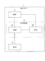
まず、本実施の形態に係る表示システム1の構成例について図1を用いて説明する。図1は、本実施の形態に係る表示システム1の構成例を示すブロック図である。
First, a configuration example of the
表示システム1は、例えば、車両等の移動体において用いられ、車両の運転を支援するシステムである。表示システム1は、車載機器であってもよいし、車両に持ち込まれる機器であってもよい。また、本実施の形態では、ユーザが車両の乗員、特に車両の運転者である例について説明するが、その限りではない。さらには、表示システム1は、ユーザが身体に装着に可能なウェラブルコンピュータ(例えば、後述するHMD)において用いられてもよい。
The
図1において、表示システム1は、取得部10、表示制御装置20、および表示部30を有する。また、表示制御装置20は、制御部201および判定部202を有する。
In FIG. 1, the
取得部10は、車両が走行する道路区間の情報を取得する。具体的には、取得部10は、所定のタイミングで、区間長情報および制限速度情報を取得する。区間長情報とは、道路区間の道のり(例えば、50m、1.2km等)を示す情報である。制限速度情報とは、道路区間の制限速度(例えば、60km/h、50km/h等)を示す情報である。
The
本実施の形態では、例として、区間長情報および制限速度情報は、地図情報に含まれる道路区間ごとに予め対応付けられており、地図情報とともに所定の記憶装置に格納されているとする。所定の記憶装置は、表示システム1内に備えられてもよいし、表示システム1外に備えられたデータベースでもよい。そして、取得部10は、例えば、車両が走行する道路区間が切り替わる度に、所定の記憶装置から区間長情報および制限速度情報を取得する。取得部は、たとえば、車両に搭載された、もしくは持ち込まれた機器のGPS(Grobal Positoning System)と、地図情報とに基づいて走行する道路区間を特定することで道路区間の区間長情報および制限速度情報を取得してもよいし、または、取得部は、道路に設置された設備から無線通信により車両が走行する道路区間の区間長情報および制限速度情報を取得してもよい。いずれにしても、車両が走行する道路区間を特定する方法、および、特定された道路区間の区間長情報および制限速度情報を取得する方法は公知技術で実現されるため、詳細な説明を省略する。
In this embodiment, as an example, it is assumed that the section length information and the speed limit information are associated in advance for each road section included in the map information, and are stored in a predetermined storage device together with the map information. The predetermined storage device may be provided in the
表示部30は、取得部10において取得された情報に基づいた所定画像を生成し、所定画像を表示媒体(図示せず)に表示させる。具体的には、表示部30は、制御部201の制御情報に基づいて、画像を生成し、生成した画像を表示媒体に投影する。表示媒体は、例えば、ヘッドアップディスプレイ(Head Up Display:HUD)である。かかる場合、表示部30は、所定画像を表示媒体に投射し、車両の乗員に虚像として認識させる。本開示では、所定画像を表示媒体に投射して乗員に虚像として認識させることと、所定画像を表示媒体に表示することとは同義であるとして、以下説明する。すなわち、以下の説明において、HUDへ所定画像が投影されて、乗員に虚像として視認される事象を、表示という。
The
表示部30は、例えば、プロジェクタ機能を有し、生成した画像を表示媒体であるHUDへ直接投影する。これにより、画像がHUDに表示される。なお、表示部30は、プロジェクタ機能を用いる代わりに、例えば、ホログラムの原理を用いてHUDに虚像を表示させてもよい。ホログラムを用いる場合、導光板の内部全反射条件を満たす平行光束群を内部全反射して導光する導光板を用いる方式でもよい。なお、導光板を用いた方式においては、プロジェクタのように画像データを直接的に投影するものではないが、説明の便宜上、プロジェクタ方式と同様に投影または表示という。
The
なお、表示媒体としては、HUDに限定されない。表示媒体は、例えば、LCD(Liquid Crystal Display)、HUD、HMD(Head‐Mounted DisplayまたはHelmet‐Mounted Display)、眼鏡型ディスプレイ(Smart Glasses)、ナビゲーション用ディスプレイ、メータディスプレイ、その他の専用のディスプレイなどが適用される。また、HUDは、例えば、車両のウインドシールドであってもよいし、別途設けられるガラス面、プラスチック面などであってもよい。また、ウインドシールドは、例えば、フロントガラスであってもよいし、車両のサイドガラスまたはリアガラスであってもよい。いずれの場合も、画像は表示媒体に表示される。 Note that the display medium is not limited to the HUD. Examples of display media include LCD (Liquid Crystal Display), HUD, HMD (Head-Mounted Display or Helmet-Mounted Display), glasses-type display (Smart Glasses), navigation display, meter display, and other dedicated displays. Applied. The HUD may be, for example, a windshield of a vehicle, or may be a separately provided glass surface, plastic surface, or the like. The windshield may be, for example, a windshield, a vehicle side glass, or a rear glass. In either case, the image is displayed on the display medium.
制御部201は、取得部10が第n(nは1以上の整数)の道路区間(以下、第n区間という)の情報を取得した場合、表示媒体に表示されたときに第n区間の制限速度を示す視認画像となる第nの所定画像を生成して表示媒体に表示するように表示部30を制御する。ここで、上記第n区間の情報には、第n区間の制限速度を示す第n区間の制限速度情報と、第n区間の区間長(以下、第n区間長という)を示す第nの区間長情報とが含まれている。
When the
制限速度を示す視認画像とは、制限速度の数字情報のみの画像であってもよいし、標識のように制限速度の数字情報を含む画像であってもよい(後述の図5参照)。また、制限速度を示す視認画像は、表示媒体に表示され、車両の乗員に視認される画像である。第nの所定画像は、表示部30において生成される画像である。すなわち、表示媒体に表示される制限速度を示す視認画像と、第nの所定画像とは実質的に内容が同じである。
The visual image indicating the speed limit may be an image including only speed limit numeric information, or may be an image including speed limit numeric information such as a sign (see FIG. 5 described later). The visual image indicating the speed limit is an image that is displayed on the display medium and is visually recognized by the vehicle occupant. The nth predetermined image is an image generated in the
以下、第1区間、第2区間を例に挙げて説明する。判定部202は、取得部10が第1区間の情報を取得した後、第2区間の情報を取得した場合、第2区間の区間長が設定区間長より短いか否かを判定し、第1区間の制限速度と第2区間の制限速度とが異なるか否かを判定する。ここで、上記第2区間の情報には、第2区間の制限速度を示す第2区間の制限速度情報と、第2区間長を示す第2の区間長情報とが含まれている。また、設定区間長とは、道路区間長が短いか長いかを判別するための閾値として予め設定された値(例えば、30m)である。
Hereinafter, the first section and the second section will be described as examples. When the
制御部201は、判定部202において、第2区間長が設定区間長よりも短くないと判定され、かつ、第1区間の制限速度と第2区間の制限速度とが異なると判定された場合、第1の所定画像を表示部30に生成させて表示媒体に表示させる制御から、表示媒体に表示されたときに第2区間の制限速度を示す視認画像となる第2の所定画像を表示部30に生成させて表示媒体に表示させる制御への切り替えを、予め定められた第1の切替方法により実行する。
When the
一方で、制御部201は、判定部202において第2区間長が設定区間長よりも短いと判定された場合、第1の所定画像を表示部30に生成させて表示媒体に表示させる制御から、第2の所定画像を表示部30に生成させて表示媒体に表示させる制御への切り替えを、第1の切替方法と異なる第2の切替方法により実行する。
On the other hand, when the
なお、制御部201は、上述した制御の切り替えの指示および切り替えた制御の内容を示す制御情報を表示部30へ出力することで、表示部30を制御する。
The
なお、表示システム1は、上述した表示媒体を含む構成であってもよい。また、表示システム1において、表示制御装置20と表示部30とを合わせたものを投影装置として構成してもよい。
The
なお、所定画像は、予めデザインが定められている画像であり、例えば、制限速度を示す道路標識であってもよいし、7セグメントディスプレイなどを用いて制限速度情報をデジタル表示として表現した画像であってもよい。 The predetermined image is an image whose design is determined in advance. For example, the predetermined image may be a road sign indicating a speed limit, or an image expressing speed limit information as a digital display using a 7-segment display or the like. There may be.
また、上述した第1の所定画像または第2の所定画像は、表示部30ではなく、表示制御装置20または図示しない他の構成要素によって生成されてもよい。
The first predetermined image or the second predetermined image described above may be generated not by the
表示システム1において生成される第1の所定画像または第2の所定画像は、例えば、虚像として運転者に視認される。このとき、第1の所定画像または第2の所定画像は、運転者の視界に重畳されるように表示媒体に投影されてもよい。なお、表示媒体に投影された画像が虚像として運転者に視認される原理は、公知技術であるため、説明を省略する。
The first predetermined image or the second predetermined image generated in the
以上、本実施の形態に係る表示システム1の構成例について説明した。
The configuration example of the
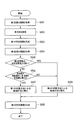
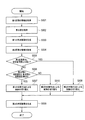
次に、本実施の形態に係る表示システム1の動作例1について図2を用いて説明する。図2は、本実施の形態に係る表示システム1の動作例1を示すフローチャートである。図2のフローは、車両が第1区間を走行した後、第2区間へ進入した場合の表示システムの処理フローである。取得部10は、車両が走行する道路区間が切り替わるごとに、切り替わった後の道路区間の情報(区間長情報および制限速度情報)を取得する。図2のフローにおいては、車両が走行する道路区間が切り替わる際に、切り替わる前の第2区間の情報が、切り替わった後の第1区間の情報として扱われ、S004以降の処理が行われる。また、以下の説明では道路リンクと道路区間とは同じ意味として説明する。
Next, an operation example 1 of the
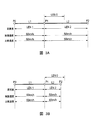
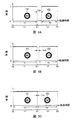
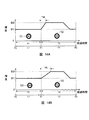
まず、取得部10は、第1区間の情報を取得する(ステップS001)。ここでいう第1区間の情報は、例えば、図3に示すノードP0とノードP1との間の道路リンクL1の情報である。この道路リンクL1の情報は、車両が走行する道路リンクが道路リンクL1に切り替わった時に取得される。また、道路リンクL1の情報には、第1区間長情報および第1区間の制限速度情報が含まれる。ここでは例として、第1区間の制限速度情報が示す第1区間の制限速度は、図3に示すように60km/hであるとする。また、第1区間の区間長は、図3に示す道路リンクL1の区間長LEN1である。なお、図3に示す比較速度については、後述の動作例2で説明する。
First, the
次に、制御部201は、第1区間の制限速度情報に基づいて、表示媒体に表示されたときに第1区間の制限速度(例えば、60km/h)を示す視認画像となる第1の所定画像を生成するように表示部30を制御する(ステップS002)。ここでいう視認画像は、例えば、後述する図5の第1の視認画像101である。
Next, based on the speed limit information of the first section, the
次に、表示部30は、制御部201からの制御によって、第1の所定画像を生成し、それを表示媒体に表示させる(ステップS003)。
Next, the
次に、取得部10は、第2区間の情報を取得する(ステップS004)。ここでいう第2区間の情報は、例えば、図3に示すノードP1とノードP2との間の道路リンクL2の情報である。この道路リンクL2の情報は、車両が走行する道路リンクが道路リンクL2に切り替わった時に取得される。また、道路リンクL2の情報には、第2の区間長情報および第2区間の制限速度情報が含まれる。ここでは例として、第2区間の制限速度情報が示す第2区間の制限速度は、図3に示すように50km/hであるとする。すなわち、ここでは、第1区間の制限速度と第2区間の制限速度とが異なるとする。
Next, the
なお、第1のタイミングと、第2のタイミングとは実質的に一致している。すなわち、道路リンクL1から道路リンクL2へ車両が走行する道路が切り替わる第1のタイミングと、第1の所定画像が表示媒体に表示されなくなる第2のタイミングとは一致するのが望ましいが、装置の処理時間の遅延などによって、必ずしも一致している必要はない。第1のタイミングより第2のタイミングが早くても、遅くてもよく、本開示の範囲を限定するものではない。 Note that the first timing and the second timing substantially coincide with each other. That is, it is desirable that the first timing at which the road on which the vehicle travels from the road link L1 to the road link L2 is switched coincides with the second timing at which the first predetermined image is not displayed on the display medium. It is not always necessary to agree with the processing time delay. The second timing may be earlier or later than the first timing, and does not limit the scope of the present disclosure.
次に、判定部202は、第2区間長が設定区間長より短いか否かを判定する(ステップS005)。ここでいう第2区間長は、図3に示す道路リンクL2の区間長LEN2である。また、設定区間長は、図3に示す設定区間長LEN0である。
Next, the
上記ステップS005における判定の結果、第2区間長が設定区間長より短くない場合(ステップS005:NO)、フローはステップS006へ進む。 If the result of determination in step S005 is that the second section length is not shorter than the set section length (step S005: NO), the flow proceeds to step S006.
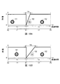
例えば図3Aは、道路リンクL2の区間長LEN2が設定区間長LEN0よりも短くない場合を示している。また、この場合の車両の走行例を図4Aに示す。図4Aでは、第1区間の制限速度SPD1が60km/hである道路リンクL1と、第2区間の制限速度SPD2が50km/hである道路リンクL2とがノードP1で接続している。車両は、矢印Kに示すように、道路リンクL1の走行後、ノードP1で右折し、道路リンクL2を走行する。この場合、後述のステップS006では、制限速度の切り替わりを運転者に認識させやすくする制御が行われる。 For example, FIG. 3A shows a case where the section length LEN2 of the road link L2 is not shorter than the set section length LEN0. Further, FIG. 4A shows an example of traveling of the vehicle in this case. In FIG. 4A, a road link L1 whose speed limit SPD1 in the first section is 60 km / h and a road link L2 whose speed limit SPD2 in the second section is 50 km / h are connected by a node P1. As shown by the arrow K, the vehicle turns right at the node P1 after traveling on the road link L1, and travels on the road link L2. In this case, in step S006, which will be described later, control is performed so that the driver can easily recognize the change in the speed limit.
一方、上記ステップS005における判定の結果、第2区間長が設定区間長より短い場合(ステップS005:YES)、フローはステップS008へ進む。また、後述するステップS006における判定の結果、第2区間の制限速度と第1区間の制限速度が等しい場合(ステップ006:NO)も、フローはステップS008へ進む。 On the other hand, if the result of determination in step S005 is that the second section length is shorter than the set section length (step S005: YES), the flow proceeds to step S008. Also, as a result of determination in step S006, which will be described later, also when the speed limit in the second section is equal to the speed limit in the first section (step 006: NO), the flow proceeds to step S008.
例えば図3Bは、道路リンクL2の区間長LEN2が設定区間長LEN0よりも短い場合を示している。また、この場合の車両の走行例を図4Bに示す。図4Bでは、第1区間の制限速度SPD1が60km/hである道路リンクL1と、第2区間の制限速度SPD2が50km/hである道路リンクL2とがノードP1で接続している。車両は、矢印Kに示すように、道路リンクL1の走行後、ノードP1で右折し、道路リンクL2を走行する。この場合、後述のステップS008では、制限速度の切り替わりによる視覚的な煩わしさを運転者に与えないようにする制御が行われる。制限速度が変化した場合は、変化したことを的確に運転者には認識させるべきではある。しかしながら、道路区間が短い場合には、頻繁に制限速度の変化の通知が行われてしまうことになり、反って運転者に煩わしくさせてしまうという問題がある。これを発生させないようにするためである。 For example, FIG. 3B shows a case where the section length LEN2 of the road link L2 is shorter than the set section length LEN0. Further, FIG. 4B shows an example of traveling of the vehicle in this case. In FIG. 4B, the road link L1 whose speed limit SPD1 in the first section is 60 km / h and the road link L2 whose speed limit SPD2 in the second section is 50 km / h are connected at the node P1. As shown by the arrow K, the vehicle turns right at the node P1 after traveling on the road link L1, and travels on the road link L2. In this case, in step S008 to be described later, control is performed so as not to give the driver visual inconvenience due to switching of the speed limit. If the speed limit changes, the driver should be made aware of the change. However, when the road section is short, a change in the speed limit is frequently notified, which causes a problem that the driver is troublesome. This is to prevent this from occurring.
また、第2区間の区間長が短くなく(ステップS005:NO)、かつ、第2区間の制限速度と第1区間の制限速度とが等しい場合(ステップS006:NO)も、制限速度の切り替わりによる視覚的な煩わしさを運転者に与えないようにする制御が行われる。第2区間の区間長が短くない場合でも、第2区間の制限速度が、第1区間の制限速度と等しい場合は、制限速度が変化していないため、これを顕著に通知してしまうと反って運転者に煩わしくさせてしまうという問題を回避するためである。 Further, when the section length of the second section is not short (step S005: NO) and the speed limit of the second section is equal to the speed limit of the first section (step S006: NO), the speed limit is switched. Control is performed so as not to give the driver visual inconvenience. Even if the section length of the second section is not short, if the speed limit of the second section is equal to the speed limit of the first section, the speed limit does not change. This is to avoid the problem of making the driver bothersome.
上記のとおり、ステップS005において、第2区間長が設定区間長より短くない場合(ステップS005:NO)、次に、判定部202は、第2区間の制限速度は第1区間の制限速度と異なるか判定する(ステップS006)。そして、判定の結果、第2区間の制限速度が第1区間の制限速度と異なる場合(ステップS006:YES)、フローはステップS007へ進む。
As described above, when the second section length is not shorter than the set section length in step S005 (step S005: NO), the
次に、制御部201は、判定部202において第2区間長が設定区間長より短くないと判定され(ステップS005:NO)、かつ、判定部202において第1区間の制限速度と第2区間の制限速度とが異なると判定された場合(ステップS006:YES)、第1の所定画像を表示部30に生成させて表示媒体に表示させる制御から、表示媒体に表示されたときに第2区間の制限速度を示す視認画像を表す第2の所定画像を表示部30に生成させて表示媒体に表示させる制御への切り替えを、予め定められた第1の切替方法により実行する(ステップS007)。
Next, the
第2の所定画像は、表示媒体に表示されたときに第2区間の制限速度(例えば、50km/h)を示す視認画像となる画像である。ここでいう視認画像は、例えば、後述する図5の第2の視認画像102である。なお、第1の切替方法による制御の切り替えの例については、図5Aを用いて後述する。
The second predetermined image is an image that becomes a visual image indicating the speed limit (eg, 50 km / h) of the second section when displayed on the display medium. The visual image here is, for example, a second
一方で、制御部201は、判定部202において第2区間長が設定区間長より短いと判定された場合(ステップS005:YES)、第1の所定画像を表示部30に生成させて表示媒体に表示させる制御から、第2の所定画像を表示部30に生成させて表示媒体に表示させる制御への切り替えを、第1の切替方法と異なる第2の切替方法により実行する(ステップS008)。
On the other hand, when the
また、制御部201は、判定部202において、第2の区間長が設定区間長よりも短くないと判定され、かつ、第1区間の制限速度と第2区間の制限速度とが等しいと判定された場合、第1の所定画像を表示部に生成させて表示媒体に表示させる制御から、第2の所定画像を表示部に生成させて表示媒体に表示させる制御への切替を第2の切替方法により実行する(ステップS008)。
In addition, the
なお、第2の切替方法による制御の切り替えの例については、図5B、図5Cを用いて後述する。 An example of control switching by the second switching method will be described later with reference to FIGS. 5B and 5C.
ステップS007、S008において、制御部201は、制御の切り替えの指示および切り替えた制御の内容を示す制御情報を表示部30へ出力する。
In steps S007 and S008, the
次に、表示部30は、制御部201からの制御情報に基づいて、第2の所定画像の生成を行い、その画像を表示媒体に投影する(ステップS009)。
Next, the
なお、図4では、交差点を右折する例を示したが、第1区間、第2区間の、区間長と制限速度の関係が上述のごとくであればよく、交差点を右左折する場合に限らず、交差点を直進する場合も含まれる。 In addition, although the example which turns right at an intersection was shown in FIG. 4, as long as the relationship between the section length and the speed limit of the 1st section and the 2nd section is as above-mentioned, it is not restricted to the case of turning right and left at the intersection. This includes the case of going straight through an intersection.
次に、図2のステップS007、S008で説明した、第1の切替方法、第2の切替方法による制御(表示媒体に表示される画像)の切り替えの具体例について、図5を用いて以下に説明する。 Next, a specific example of switching of the control (image displayed on the display medium) by the first switching method and the second switching method described in steps S007 and S008 in FIG. 2 will be described below with reference to FIG. explain.
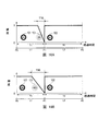
図5において、縦軸は、表示媒体に表示される画像の輝度(任意の値を基準とした相対値)を示し、横軸は、上述した所定画像が表示媒体に表示される時間を示す。図5において、ノードP0〜P2および道路リンクL1、L2は、それぞれ、図3および図4におけるものと同様である。また、時間T1は、第1区間の制限速度(例えば60km/h)を示す第1の視認画像101が表示媒体に表示される時間を示す。時間T2は、第2区間の制限速度(例えば50km/h)を示す第2の視認画像102が表示媒体に表示される時間を示す。
In FIG. 5, the vertical axis indicates the luminance (relative value based on an arbitrary value) of the image displayed on the display medium, and the horizontal axis indicates the time during which the predetermined image is displayed on the display medium. In FIG. 5, nodes P0 to P2 and road links L1 and L2 are the same as those in FIGS. 3 and 4, respectively. Moreover, time T1 shows the time when the 1st
また、図5において、第1の視認画像101および第2の視認画像102は、例えば、中央に制限速度が示される道路標識型の画像とする。なお、第1の視認画像101および第2の視認画像102は、表示媒体がHUDの場合には、虚像として乗員に視認される。
In FIG. 5, the first
図5に示すように、例えば、第1の切替方法は、制御部が、第1の所定画像を表示部に生成させて表示媒体に表示させる制御を停止した後、第1の時間の経過後に、制御部が、第2の所定画像を表示部に生成させて表示媒体に表示させる制御を開始する方法である。また、例えば、第2の切替方法は、制御部が、第1の所定画像を表示部に生成させて表示媒体に表示させる制御を停止した後、第2の時間の経過後に、制御部が、第2の所定画像を表示部に生成させて表示媒体に表示させる制御を開始する方法である。第2の時間は、ゼロ以上かつ第1の時間未満である。 As shown in FIG. 5, for example, in the first switching method, after the control unit stops the control of generating the first predetermined image on the display unit and displaying the first predetermined image on the display medium, the first switching method is performed. In this method, the control unit starts the control of generating the second predetermined image on the display unit and displaying the second predetermined image on the display medium. Further, for example, in the second switching method, after the control unit stops the control of generating the first predetermined image on the display unit and displaying the first predetermined image on the display medium, the control unit In this method, the second predetermined image is generated on the display unit and is displayed on the display medium. The second time is greater than or equal to zero and less than the first time.
図5を用いて具体例について説明する。図5Aは、第1の切替方法による制御の切り替えの具体例を説明する図である。図5B、図5Cは、第2の切替方法による制御の切り替えの具体例を説明する図である。 A specific example will be described with reference to FIG. FIG. 5A is a diagram for explaining a specific example of control switching by the first switching method. 5B and 5C are diagrams illustrating a specific example of control switching by the second switching method.
まず、図5Aを用いて第1の切替方法による制御の切り替えの具体例を説明する。図5Aは、判定部202において第2区間長が設定区間長よりも短くないと判定された場合における、制御の切り替えの具体例の説明に供するための図である。
First, a specific example of control switching by the first switching method will be described with reference to FIG. 5A. FIG. 5A is a diagram for explaining a specific example of control switching when the
時間T1の間、制御部201は、表示媒体に表示されたときに第1の視認画像101を表す第1の所定画像を生成して、所定の輝度で表示媒体に表示するように表示部30を制御する。これにより、第1の視認画像101が表示媒体に表示される。
During time T1, the
その後、道路リンクL2へ車両が進入し、判定部202において第2区間長LEN2が設定区間長LEN0よりも短くないと判定され、かつ、判定部202において第1区間の制限速度と第2区間の制限速度とが異なると判定されると、制御部201は、第1の視認画像101を表す第1の所定画像の生成を停止するように表示部30を制御することで、表示媒体への表示が停止される。これにより、第1の視認画像101は、道路リンクL2進入時において、表示媒体に表示されなくなる。
Thereafter, the vehicle enters the road link L2, the
そして、制御部201は、予め定められた第1の時間T30(例えば、0.5秒または1秒等)の経過後、表示媒体に表示されたときに第2の視認画像102を表す第2の所定画像を生成して、所定の輝度(例えば、第1の視認画像101と同じ輝度)で表示媒体に表示するように表示部30を制御する。これにより、第2の視認画像102が表示媒体に表示される。なお、制御部201は、予め生成された第2の視認画像102を表す第2の所定画像を所定の記憶装置から読み出し、所定の輝度で表示するように表示部30を制御してもよい。
Then, the
このように、第2区間長が設定区間長よりも短くなく、かつ、第1区間の制限速度と第2区間の制限速度とが異なる場合では、表示媒体において、第1の視認画像101の表示が消えてから予め定められた第1の時間T30が経過した後に、第2の視認画像102の表示が行われる。そのため、画像の切り替わりがより顕著になり、運転者は、画像の切り替わりを認識しやすくなる。例えば、運転者が、表示媒体を注視していなくても、たとえば周辺視野で画像の切り替わりを感じることができる。
As described above, when the second section length is not shorter than the set section length and the speed limit of the first section is different from the speed limit of the second section, the first
次に、図5Bを用いて第2の切替方法による制御の切り替えの具体例を説明する。図5Bは、判定部202において第2区間長が設定区間長よりも短いと判定された場合における、制御の切り替えの具体例の説明に供するための図である。
Next, a specific example of control switching by the second switching method will be described with reference to FIG. 5B. FIG. 5B is a diagram for explaining a specific example of control switching when the
図5Bは、第1の時間T30ではなく、第2の時間T40が適用される点で図5Aと異なる。その点以外は、図5Aと同様であるので、ここでの説明は省略する。予め定められた時間T40は、例えば、ゼロ以上かつ時間T30未満である。 FIG. 5B differs from FIG. 5A in that the second time T40 is applied instead of the first time T30. Except for this point, it is the same as FIG. The predetermined time T40 is, for example, zero or more and less than the time T30.
一般に、人間が知覚できる明暗の限界周波数である臨界融合周波数(CFF:Critical Flicker Frequency)は、30〜40Hzと言われている。時間T40は、このCFFに基づいて、例えば20msec以下の値に設定すればよい。または、図5Cに示すように時間T40をゼロに設定することで、第1の視認画像101から第2の視認画像102へ直ちに表示が切り替わるようにしてもよい。このようにすることで、運転者は、画像の切り替わりによる視覚的な煩わしさを、さらに感じにくくなる。
Generally, it is said that a critical fusion frequency (CFF: Critical Flicker Frequency), which is a light and dark limit frequency perceivable by humans, is 30 to 40 Hz. The time T40 may be set to a value of 20 msec or less, for example, based on this CFF. Alternatively, as shown in FIG. 5C, the display may be immediately switched from the first
このように、第2区間長が設定区間長よりも短い場合、または、第2区間の区間長が短くなく、かつ、第2区間の制限速度が、第1区間の制限速度と等しい場合では、表示媒体において、第1の視認画像101の表示が消えてから予め定められた時間T40が経過した後、第2の視認画像102の表示が行われる。そのため、第2区間長が設定区間長よりも短くなく、かつ、第1区間の制限速度と第2区間の制限速度が異なる場合と比べて画像の切り替わりが顕著にならず、運転者は、画像の切り替わりによる視覚的な煩わしさを感じにくくなる。
Thus, when the second section length is shorter than the set section length, or when the section length of the second section is not short and the speed limit of the second section is equal to the speed limit of the first section, On the display medium, the second
なお、上記説明においては、第2区間長が設定区間長よりも短く、かつ、道路リンクが切り替わっても制限速度が変化しない場合、第2の切替方法による制御の切り替えが行われるとして説明した。かかる場合、第2の切替方法では、第2の時間T40がゼロに設定されている場合が含まれる。T40がゼロである場合、制御部は、道路リンクL1に対応する制限速度情報の表示から、道路リンクL2に対応する制限速度情報の表示へ、データ処理を切り替えるが、ユーザにとっては実質的に表示の切替は起きていないように認識される。このように、時間T40がゼロに設定されることによって、運転者に対して視覚的な煩わしさを殆どまったく与えないという効果を奏する。 In the above description, when the second section length is shorter than the set section length and the speed limit does not change even when the road link is switched, the control switching by the second switching method is performed. In such a case, the second switching method includes a case where the second time T40 is set to zero. When T40 is zero, the control unit switches the data processing from the display of the speed limit information corresponding to the road link L1 to the display of the speed limit information corresponding to the road link L2, but is substantially displayed for the user. It is recognized that no switching has occurred. As described above, the time T40 is set to zero, so that there is an effect that the driver is hardly given any visual inconvenience.
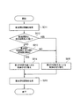
なお、図6に示すように、第2区間長が設定区間長よりも短くなく(ステップS005:NO)、かつ、道路リンクが切り替わっても制限速度が変化しない場合(ステップS006:NO)、第1の切替方法による切替方法および第2の切替方法とは異なる、第3の切替方法による制御の切り替え(ステップS010)を行ってもよい。すなわち、第2区間長が設定区間長よりも短い場合の切替方法(ステップS008)と、第2区間長が設定区間長よりも短くなく(ステップS005:NO)、かつ、道路リンクが切り替わっても制限速度が変化しない場合(ステップS006:NO)の切替方法とが異なってもよい。具体的には、第3の切替方法は、時間T40がゼロ以上時間T30未満と同様であるが、時間T40がゼロの場合である。すなわち、第3の切替方法は、制御部は、道路リンクL1に対応する制限速度情報の表示から、道路リンクL2に対応する制限速度情報の表示へ、データ処理を切り替えるだけであり、ユーザであるドライバにとっては実質的に表示の切替は起きていないように認識される。換言すれば、第3の切替方法によって制御を切り替える場合、制御を切り替える前と、制御を切り替えた後とで、表示媒体に表示される視認画像は変化していない。このように、表示媒体において、第1の視認画像101の表示が消えてから、実質的にゼロ時間経過後、第2の視認画像102の表示が行われることで、運転者に対して視覚的な煩わしさを殆ど与えないという効果を奏する。
As shown in FIG. 6, when the second section length is not shorter than the set section length (step S005: NO) and the speed limit does not change even when the road link is switched (step S006: NO), The control switching (step S010) by the third switching method, which is different from the switching method by the first switching method and the second switching method, may be performed. That is, even when the second section length is shorter than the set section length (step S008), the second section length is not shorter than the set section length (step S005: NO), and the road link is switched. When the speed limit does not change (step S006: NO), the switching method may be different. Specifically, the third switching method is the same as when the time T40 is zero or more and less than the time T30, but the time T40 is zero. That is, in the third switching method, the control unit only switches the data processing from the display of the speed limit information corresponding to the road link L1 to the display of the speed limit information corresponding to the road link L2, and is a user. The driver recognizes that display switching has not occurred substantially. In other words, when the control is switched by the third switching method, the visual image displayed on the display medium is not changed before the control is switched and after the control is switched. As described above, the display of the second
また、上記の説明においては、判定部により第2の区間長が設定区間長よりも短いと判定された場合には、第2の切替方法により切替を実行するとして説明したが、この限りではない。すなわち、判定部により第2の区間長が設定区間長よりも短く、かつ、第1区間の制限速度と第2区間の制限速度とが異なる場合には第2の切替方法により切替を実行し、判定部により第2の区間長が設定区間長よりも短く、かつ、第1区間の制限速度と第2区間の制限速度とが等しい場合には第3の切替方法により切替を実行してもよい。第3の切替方法は、ドライバにとっては切替が起きていないように認識される。 In the above description, when the determination unit determines that the second section length is shorter than the set section length, it is described that switching is performed by the second switching method, but this is not restrictive. . That is, when the second section length is shorter than the set section length by the determination unit and the speed limit of the first section is different from the speed limit of the second section, switching is performed by the second switching method, When the second section length is shorter than the set section length by the determination unit and the speed limit of the first section is equal to the speed limit of the second section, switching may be executed by the third switching method. . The third switching method is recognized by the driver as if switching has not occurred.
なお、車両が走行する道路リンクが、道路リンクL1から道路リンクL2へ切り替わる時点と、制限速度の表示が切り替わる時点とが実質的に一致することが望ましい。運転者に対して、リアルタイムで制限速度の情報変化を通知できるためである。しかしながら、本開示においては、車両が走行する道路リンクが道路リンクL1から道路リンクL2へ切り替わる時点と、制限速度の表示が切り替わる時点とは必ずしも一致する必要はなく、一定の時間だけずれることは許容され、本開示の範囲を限定するものではない。このことは、後述する他の具体例(例えば、図13〜図17)においても同様である。 It is desirable that the time when the road link on which the vehicle travels switches from the road link L1 to the road link L2 substantially coincides with the time when the display of the speed limit changes. This is because the driver can be notified of information on the speed limit information in real time. However, in the present disclosure, the time point when the road link on which the vehicle travels switches from the road link L1 to the road link L2 does not necessarily coincide with the time point when the display of the speed limit changes, and it is allowed to deviate by a certain time. And does not limit the scope of the present disclosure. The same applies to other specific examples (for example, FIGS. 13 to 17) described later.
以上、本実施の形態に係る表示システム1の動作例1について説明した。
The operation example 1 of the
次に、本実施の形態に係る表示システム1の動作例2について図7を用いて説明する。図7は、本実施の形態に係る表示システム1の動作例2を示すフローチャートである。図7のフローは、車両が走行する道路区間が切り替わる際に行われる。例えば、図7のフローは、第2区間から第3区間(第3の道路区間)へ車両が進入した場合の表示システムの処理フローである。以下の説明では、図2の動作例1と同様に、道路区間が道路リンクである場合を例とする。また、以下では、図2のステップS008、S009を経た後の処理を例に挙げて説明する。
Next, an operation example 2 of the
なお、本実施の形態に係る表示システム1の動作例2は、動作例1における第2の切替方法により制御の切り替えが実行された後の動作例である。動作例1における第2の切替方法により制御の切り替えが実行された後は、動作例1を繰り返すとする。
The operation example 2 of the
本実施の形態に係る表示システム1の動作例2において、判定部は、第2の切替方法により制御の切り替えが実行された後、取得部により第3区間の区間長である第3の区間長および第3区間の制限速度の情報が取得された場合、第3の区間長が設定区間長より短いか否かを判定し、第3の区間長が設定区間長よりも短くないと判定した場合、第3区間の制限速度が第1区間の制限速度と異なるか否かを判定し、制御部は、判定部により第3区間の制限速度が第1区間の制限速度と異なると判定された場合、第2の所定画像を表示部に生成させて表示媒体に表示させる制御から、表示媒体に表示されたときに第3区間の制限速度を示す視認画像となる第3の所定画像を表示部に生成させて表示媒体に表示させる制御への切り替えを第1の切替方法により実行する。具体的には、以下において説明する。
In the operation example 2 of the
まず、取得部10は、上述された動作例1において第2の切替方法により制御の切り替えが実行された後に、第3区間の情報を取得する(ステップS011)。ここでいう第3区間の情報は、例えば、図8に示すノードP2とノードP3との間の道路リンクL3の情報である。この道路リンクL3の情報は、車両が走行する道路リンクが道路リンクL3に切り替わった時に取得される。また、道路リンクL3の情報には、第3の道路区間の区間長(第3区間長)を示す第3の区間長情報と、第3の道路区間の制限速度を示す第3区間の制限速度情報とが含まれる。
First, the
次に、判定部202は、第3区間長が設定区間長より短いか否かを判定する(ステップS012)。ここでいう第3区間長は、図8Aまたは図8Bに示す道路リンクL3の区間長LEN3である。また、設定区間長は、図8に示す設定区間長LEN0である。なお、図8A、図8Bは共に、第3区間長が設定区間長より短くない場合を示している。
Next, the
上記ステップS012における判定の結果、第3区間長が設定区間長より短くない場合(ステップS012:NO)、フローはステップS013へ進む。一方、上記ステップS012における判定の結果、第3区間長が設定区間長より短い場合(ステップS012:YES)、フローはステップS015へ進む。 If the result of determination in step S012 is that the third section length is not shorter than the set section length (step S012: NO), the flow proceeds to step S013. On the other hand, if the result of determination in step S012 is that the third section length is shorter than the set section length (step S012: YES), the flow proceeds to step S015.
上記ステップS012において第3区間長が設定区間長より短くない場合(ステップS012:NO)、判定部202は、第3区間の制限速度が第1区間の制限速度と異なるか否かを判定する(ステップS013)。ここでは例として、道路リンクL1の制限速度として60km/hが設定されているとする(図8A、図8B参照)。
When the third section length is not shorter than the set section length in step S012 (step S012: NO), the
上記ステップS013における判定の結果、第3区間の制限速度が第1区間の制限速度と異なる場合(ステップS013:YES)、フローはステップS014へ進む。第3区間の制限速度が第1区間の制限速度と異なる場合は、例えば図8Aに示すように、道路リンクL3の制限速度が50km/hであり、道路リンクL1の制限速度が60km/hである場合である。また、この場合の車両の走行例を図9A、図9Bに示す。図9A、図9Bにおける各符号は図5と同様であるので、それらの説明は省略する。 If the result of determination in step S013 is that the speed limit in the third section is different from the speed limit in the first section (step S013: YES), the flow proceeds to step S014. When the speed limit of the third section is different from the speed limit of the first section, for example, as shown in FIG. 8A, the speed limit of the road link L3 is 50 km / h, and the speed limit of the road link L1 is 60 km / h. This is the case. Further, examples of traveling of the vehicle in this case are shown in FIGS. 9A and 9B. Since the reference numerals in FIGS. 9A and 9B are the same as those in FIG. 5, their descriptions are omitted.
上記ステップS013における判定の結果、第3区間の制限速度が第1区間の制限速度と等しい場合(ステップS013:NO)、フローはステップS015へ進む。第3区間の制限速度が第1区間の制限速度と等しい場合は、例えば図8Bに示すように、道路リンクL3の制限速度が60km/hであり、道路リンクL1の制限速度が60km/hである場合である。また、この場合の車両の走行例を図9C、図9Dに示す。図9C、図9Dにおける各符号は図5と同様であるので、それらの説明は省略する。 If the result of determination in step S013 is that the speed limit in the third section is equal to the speed limit in the first section (step S013: NO), the flow proceeds to step S015. When the speed limit of the third section is equal to the speed limit of the first section, for example, as illustrated in FIG. 8B, the speed limit of the road link L3 is 60 km / h, and the speed limit of the road link L1 is 60 km / h. This is the case. In addition, examples of traveling of the vehicle in this case are shown in FIGS. 9C and 9D. Since the reference numerals in FIGS. 9C and 9D are the same as those in FIG. 5, their descriptions are omitted.
そして、制御部201は、判定部202において第3区間の制限速度が第1区間の制限速度と異なると判定された場合(ステップS013:YES)、予め定められた第1の切替方法により、第2の所定画像を表示部30に生成させる制御から、第3の所定画像を表示部30に生成させる制御へ切り替える(ステップS014)。第3の所定画像は、表示媒体に表示されたときに第3区間の制限速度を示す視認画像となる画像である。ここでいう視認画像は、例えば、後述する図11Aの第3の視認画像103aである。なお、第1の切替方法による制御の切り替えの例については、図11Aを用いて後述する。
Then, when the
ステップS014、S015において、制御部201は、制御の切り替えの指示および切り替えた制御の内容を示す制御情報を表示部30へ出力する。
In steps S <b> 014 and S <b> 015, the
次に、表示部30は、制御部201からの制御情報に基づいて、第3の所定画像の生成を行い、その画像を表示媒体に投影する(ステップS016)。
Next, the
なお、上記の説明では、第3区間長が設定区間長よりも短い場合には、第2の切替方法による制御の切り替えが実行されるとして説明したが、その限りではない。例えば、図10に示すように、判定部202はさらに第3区間の制限速度が第2区間の制限速度と異なるか否かを判定してもよい(ステップS017)。図10では、第3区間長が設定区間長よりも短い場合(ステップS012:YES)において、第3区間の制限速度が第2区間の制限速度と異なるとき(ステップS017:YES)は、第2の切替方法による制御の切替を実行する(ステップS015)。その一方で、第3区間の制限速度が第2区間の制限速度と等しいとき(ステップS017:NO)には、上記動作例1で説明した第3の切替方法により制御の切替を実行してもよい(ステップS018)。
In the above description, when the third section length is shorter than the set section length, it has been described that the control switching by the second switching method is executed. For example, as shown in FIG. 10, the
第3の切替方法において、制御部201は、道路リンクL2に対応する制限速度情報の表示から、道路リンクL3に対応する制限速度情報の表示へ、データ処理を切り替えるだけであり、ユーザであるドライバにとっては実質的に表示の切替は起きていないように認識される。換言すれば、第3の切替方法によって制御を切り替える場合、制御を切り替える前と、制御を切り替えた後とで、表示媒体に表示される視認画像は変化していない。このように、表示媒体において、第2の視認画像の表示が消えてから、実質的にゼロ時間経過後、第3の視認画像の表示が行われることで、運転者に対して視覚的な煩わしさを殆ど与えないという効果を奏する。
In the third switching method, the
次に、図7のステップS014、S015で説明した、第1の切替方法、第2の切替方法による制御(表示媒体に表示される画像)の切り替えの具体例について、図11を用いて以下に説明する。 Next, a specific example of control (image displayed on the display medium) by the first switching method and the second switching method described in steps S014 and S015 in FIG. 7 will be described below with reference to FIG. explain.
図11において、縦軸は、表示媒体に表示される画像の輝度(任意の値を基準とした相対値)を示し、横軸は、上述した所定画像が表示媒体に表示される時間を示す。図11において、ノードP0〜P3および道路リンクL1〜L3は、それぞれ、図8および図9に対応する。また、時間T1は、第1区間の制限速度(例えば60km/h)を示す第1の視認画像101が表示媒体に表示される時間を示す。時間T2は、第2区間の制限速度(例えば50km/h)を示す第2の視認画像102が表示媒体に表示される時間を示す。時間T3aは、第3区間の制限速度(例えば50km/h)を示す第3の視認画像103aが表示媒体に表示される時間を示す。時間T3bは、第3区間の制限速度(例えば60km/h)を示す第3の視認画像103bが表示媒体に表示される時間を示す。
In FIG. 11, the vertical axis indicates the luminance (relative value based on an arbitrary value) of the image displayed on the display medium, and the horizontal axis indicates the time during which the predetermined image is displayed on the display medium. In FIG. 11, nodes P0 to P3 and road links L1 to L3 correspond to FIGS. 8 and 9, respectively. Moreover, time T1 shows the time when the 1st
また、図11において、第1の視認画像101、第2の視認画像102、第3の視認画像103a、103bは、例えば、中央に制限速度が示される道路標識型の画像とする。なお、これらの視認画像は、表示媒体がHUDの場合には、虚像として乗員に視認される。
In FIG. 11, the first
また、図11において、車両のノードP2進入時より前は図5Cと同様であるので、ここでの説明は省略する。なお、図11において、車両のノードP2進入時より前の画面表示の切り替えは図5Cに限定されず、例えば、図5Bと同じであってもよい。 Further, in FIG. 11, before the vehicle enters the node P2, it is the same as that in FIG. 5C, so the description thereof is omitted here. In FIG. 11, switching of the screen display before the time when the vehicle enters the node P2 is not limited to FIG. 5C, and may be the same as FIG. 5B, for example.
図11を用いて具体例について説明する。図11Aは、第1の切替方法による制御の切り替えの具体例を説明する図である。図11Bは、第2の切替方法による制御の切り替えの具体例を説明する図である。 A specific example will be described with reference to FIG. FIG. 11A is a diagram illustrating a specific example of control switching by the first switching method. FIG. 11B is a diagram illustrating a specific example of control switching by the second switching method.
まず、図11Aを用いて第1の切替方法による制御の切り替えの具体例を説明する。図11Aは、判定部202において第3区間長が設定区間長よりも短くないと判定され、かつ、第3区間の制限速度が第1区間の制限速度と異なると判定された場合における、制御の切り替えの具体例の説明に供するための図である。
First, a specific example of control switching by the first switching method will be described with reference to FIG. 11A. FIG. 11A shows the control in the case where the
時間T2の間、制御部201は、表示媒体に表示されたときに第2の視認画像102を表す第2の所定画像を生成して、所定の輝度で表示媒体に表示するように表示部30を制御する。これにより、第2の視認画像102が表示媒体に表示される。
During time T2, the
その後、道路リンクL3へ車両が進入すると、判定部202において、第3区間長LEN3が設定区間長LEN0よりも短くないと判定され、かつ、第3区間の制限速度50kmが第1区間の制限速度60km/hと異なると判定される。この場合、制御部201は、車両のノードP2到達時において、第2の視認画像102を表す第2の所定画像の生成を停止することで、表示媒体への表示を停止するように表示部30を制御する。これにより、第2の視認画像102は、車両のノードP2到達時において、表示媒体に表示されなくなる。
Thereafter, when the vehicle enters the road link L3, the
そして、制御部201は、予め定められた時間T30(例えば、0.5秒または1秒等)の経過後、表示媒体に表示されたときに第3の視認画像103aを表す第3の所定画像を生成して、所定の輝度(例えば、第2の視認画像102と同じ輝度)で表示媒体に表示するように表示部30を制御する。これにより、第3の視認画像103aが表示媒体に表示される。なお、制御部201は、予め生成された第3の視認画像103aを表す第3の所定画像を所定の記憶装置から読み出し、所定の輝度で表示するように表示部30を制御してもよい。
The
このように、第3区間長が設定区間長よりも短くなく、かつ、第3区間の制限速度が第1区間の制限速度と異なる場合では、表示媒体において、第2の視認画像102の表示が消えてから予め定められた時間T30が経過した後に、第3の視認画像103aの表示が行われる。そのため、画像の切り替わりがより顕著になり、運転者は、画像の切り替わりを認識しやすくなる。例えば、運転者が、表示媒体を注視していなくても、画像の切り替わりを感じることができる。
Thus, when the third section length is not shorter than the set section length and the speed limit of the third section is different from the speed limit of the first section, the display of the second
次に、図11Bを用いて第2の切替方法による制御の切り替えの具体例を説明する。図11Bは、判定部202において第3区間長が設定区間長よりも短いと判定された(図7のS012:YES)場合における、制御の切り替えの具体例の説明に供するための図である。または、図11Bは、判定部202において第3区間長が設定区間長よりも短くないと判定され(図7のS012:NO)、かつ、第3区間の制限速度が第1区間の制限速度と等しいと判定された(図7のS013:NO)場合における、制御の切り替えの具体例の説明に供するための図である。
Next, a specific example of control switching by the second switching method will be described with reference to FIG. 11B. FIG. 11B is a diagram for explaining a specific example of control switching when the
図11Bは、時間T30ではなく、時間T40が適用される点で図11Aと異なる。それ以外は、図11Aと同様であるので、ここでの説明は省略する。図11Bでは例として、予め定められた時間T40をゼロとしているが、図5Bと同様に、時間T40をゼロ以上かつ時間T30未満としてもよい。例えば、上述したとおり、時間T40は、CFFに基づいて、例えば20msec以下の値に設定してもよい。 FIG. 11B differs from FIG. 11A in that time T40 is applied instead of time T30. Other than that, it is the same as FIG. 11A, and the description is omitted here. In FIG. 11B, as an example, the predetermined time T40 is set to zero. However, similarly to FIG. 5B, the time T40 may be set to zero or more and less than time T30. For example, as described above, the time T40 may be set to a value of 20 msec or less based on the CFF, for example.
このように、第3区間長が設定区間長よりも短い場合、または、第3区間長が設定区間長よりも短くなく、かつ、第3区間の制限速度が第1区間の制限速度と等しい場合では、表示媒体において、第2の視認画像102の表示が消えてから予め定められた時間T40が経過した後、第3の視認画像103bの表示が行われる。そのため、第3区間長が設定区間長よりも短くなく、かつ、第3区間の制限速度が第1区間の制限速度と異なる場合と比べて、画像の切り替わりが顕著にならず、運転者は、画像の切り替わりによる視覚的な煩わしさを感じにくくなる。
As described above, when the third section length is shorter than the set section length, or when the third section length is not shorter than the set section length and the speed limit of the third section is equal to the speed limit of the first section. Then, on the display medium, the third
このように、動作例1における第2の切替方法により表示制御の切り替えが実行された後、すなわち、道路区間長の短い道路区間の次に、道路区間長の短くない道路区間に進入したときは、直前の道路区間長の短い道路区間の制限速度ではなく、さらにその前の、道路区間長の短くない道路区間の制限速度と、新たに取得された道路区間の制限速度とが比較される。 As described above, after the display control is switched by the second switching method in the operation example 1, that is, when the road section having a short road section length is entered next to the road section having a short road section length, The speed limit of the road section with a short road section length before the speed limit of the road section with a short road section length is compared with the speed limit of the road section with a short road section length before the speed limit of the newly acquired road section.
そして、上記比較結果が等しい場合には、変化が目立たない第2の切替方法による表示制御の切り替えが行われるので、区間ごとの制限速度表示は、その区間に該当する制限速度を行いつつ、短い区間の表示切り替えが頻繁に目立って行われるような煩わしさを排除することができる。 If the comparison results are equal, the display control is switched by the second switching method in which the change is not noticeable. Therefore, the speed limit display for each section is short while performing the speed limit corresponding to the section. It is possible to eliminate the annoyance that the display switching of the section is frequently performed conspicuously.
一方、上記比較結果が異なる場合には、区間ごとの制限速度表示は、その区間に該当する制限速度を行いつつ、短くない区間に車両が走行する道路が切り替わった時点で、変化が顕著な第1の切替方法による表示制御の切り替えが行われるので、制限速度の変化を運転者に認識させやすくすることができる。
On the other hand, when the above comparison results are different, the speed limit display for each section shows a noticeable change when the road on which the vehicle travels is switched to a non-short section while performing the speed limit corresponding to the section. Since the display control is switched by the
なお、車両が道路リンクL2から道路リンクL3へ進入する時点と、車両が走行する道路リンクが道路リンクL3に切り替わる時点とが一致することが望ましい。運転者に対して、リアルタイムで制限速度の情報変化を通知できるためである。しかしながら、本開示においては、車両が道路リンクL2から道路リンクL3へ進入する時点と、車両が走行する道路リンクが道路リンクL3に切り替わる時点とは必ずしも一致する必要はなく、一定の時間だけずれることは許容され、本開示の範囲を限定するものではない。このことは、後述する他の具体例(例えば、図13〜図17)においても同様である。 It is desirable that the time when the vehicle enters the road link L3 from the road link L2 coincides with the time when the road link on which the vehicle travels switches to the road link L3. This is because the driver can be notified of information on the speed limit information in real time. However, in the present disclosure, the time point when the vehicle enters the road link L3 from the road link L2 and the time point when the road link on which the vehicle travels switch to the road link L3 do not necessarily coincide with each other, and are shifted by a certain time. Is allowed and is not intended to limit the scope of the present disclosure. The same applies to other specific examples (for example, FIGS. 13 to 17) described later.
以上、本実施の形態に係る表示システム1の動作例2について説明した。
The operation example 2 of the
以上、動作例1、2について説明してきたが、上述した動作例1(図2)および動作例2(図7)を、図12に示すフローチャートに置き換えてもよい。例えば、図12のフローに示すように、判定部202が判定用の値として比較速度(例えば、図3、図8参照)を保持し、制御部201は、第1の切替方法による制御の切り替えの後に、判定部202が保持する比較速度を切り替え後の制限速度に更新するようにしてもよい。以下、図12のフローについて説明する。
The operation examples 1 and 2 have been described above, but the above-described operation example 1 (FIG. 2) and operation example 2 (FIG. 7) may be replaced with the flowchart shown in FIG. For example, as shown in the flow of FIG. 12, the
図12は、図2における第2区間を第n区間とし、図2におけるステップS004〜ステップS009の処理を、ステップS101〜ステップS106に置き換えて記載したものである。さらに、第1の切替方法による制御の切り替えであるステップS104の後に、第n区間の制限速度で比較速度を更新する処理をステップS107として追加したものである。 FIG. 12 shows the second section in FIG. 2 as the n-th section, and the processes in steps S004 to S009 in FIG. 2 are replaced with steps S101 to S106. Further, after step S104, which is control switching by the first switching method, processing for updating the comparison speed with the speed limit of the nth section is added as step S107.
図12のフローは、車両が走行する道路区間が切り替わるたびに行われる。まず、車両が走行する道路区間が切り替わった場合、切り替わった後の道路区間の情報が第n区間の情報として取得され(ステップS101)、第n区間長が設定区間長より短いか否かが判定される(ステップS102)。 The flow in FIG. 12 is performed every time the road section on which the vehicle travels is switched. First, when the road section on which the vehicle travels is switched, information on the road section after switching is acquired as information on the nth section (step S101), and it is determined whether the nth section length is shorter than the set section length. (Step S102).
第n区間長が設定区間長より短い場合は(ステップS102:YES)、第2の切替方法による制御の切り替えが行われる(ステップS105)。一方、第n区間長が設定区間長より短くない場合は(ステップS102:NO)、第n区間の制限速度が比較速度と異なるか否かが判定される(ステップS103)。 When the n-th section length is shorter than the set section length (step S102: YES), the control is switched by the second switching method (step S105). On the other hand, if the nth section length is not shorter than the set section length (step S102: NO), it is determined whether or not the speed limit of the nth section is different from the comparison speed (step S103).
第n区間の制限速度が比較速度と同じである場合(ステップS103:NO)、第2の切替方法による制御の切り替えが行われる(ステップS105)。一方、第n区間の制限速度が比較速度と異なる場合(ステップS103:YES)、第1の切替方法による制御の切り替えが行われる(ステップS104)。 When the speed limit in the n-th section is the same as the comparison speed (step S103: NO), the control is switched by the second switching method (step S105). On the other hand, when the speed limit in the n-th section is different from the comparison speed (step S103: YES), the control is switched by the first switching method (step S104).
第1の切替方法による表示切り替え(ステップS104)の後、判定部202が保持する比較速度が更新される(ステップS107)。すなわち、切り替え後の制限速度が新たな比較速度として判定部202に保持されることで、比較速度が更新される。その一方で、第2の切替方法による表示切り替え(ステップS105)の後は、比較速度の更新は行われない。つまり、区間長の短い道路区間に切り替わった場合は、第1の切替方法による表示切り替えは行われないので、比較速度が更新されることがない。
After the display switching by the first switching method (step S104), the comparison speed held by the
第nの所定画像が生成される(ステップS106)。 An nth predetermined image is generated (step S106).
以上のように図12のフローによれば、直前の区間長の短くない道路区間の制限速度と、新たに取得した制限速度が異なる場合に、変化が顕著な第1の切替方法による表示制御の切り替えが行われ、区間長の短い道路区間の前後は変化が目立たない第2の切替方法による表示制御の切り替えが行われるようにすることができる。以上、図12のフローについて説明した。 As described above, according to the flow of FIG. 12, when the speed limit of the road section that is not short in the immediately preceding section length is different from the newly acquired speed limit, the display control by the first switching method that is noticeable changes. Switching is performed, and display control can be switched by the second switching method in which the change is not conspicuous before and after a road section having a short section length. The flow in FIG. 12 has been described above.
また、上記動作例1、2では、図2のステップS007、S008および図7のステップS014、S015における、第1の切替方法、第2の切替方法による制御(表示媒体に表示される画像)の切り替えの具体例について、図5および図11を用いて説明した。以下では、それ以外の具体例1〜5について説明する。なお、以下の具体例1〜5では、車両が道路リンクL1から道路リンクL2へ進入した場合を例として説明するが、車両が道路リンクL2から道路リンクL3へ進入した場合にも同様に適用できるものとする。 In the operation examples 1 and 2, the control (image displayed on the display medium) by the first switching method and the second switching method in steps S007 and S008 in FIG. 2 and steps S014 and S015 in FIG. A specific example of switching has been described with reference to FIGS. Below, the other specific examples 1-5 are demonstrated. In the following specific examples 1 to 5, the case where the vehicle enters the road link L2 from the road link L1 will be described as an example, but the same applies to the case where the vehicle enters the road link L3 from the road link L2. Shall.
<具体例1>
図13を用いて具体例1について説明する。図13Aは、第1の切替方法による制御の切り替えの具体例を説明する図である。図13Bは、第2の切替方法による制御の切り替えの具体例を説明する図である。
<Specific example 1>
Specific example 1 will be described with reference to FIG. FIG. 13A is a diagram for describing a specific example of control switching by the first switching method. FIG. 13B is a diagram for describing a specific example of control switching by the second switching method.
まず、図13Aを用いて第1の切替方法による制御の切り替えの具体例を説明する。 First, a specific example of control switching by the first switching method will be described with reference to FIG. 13A.
時間T1の間、制御部201は、表示媒体に表示されたときに第1の視認画像101を表す第1の所定画像を生成して、第1の輝度B1で表示媒体に表示するように表示部30を制御する。これにより、第1の視認画像101が表示媒体に表示される。
During time T1, the
その後、道路リンクL2へ車両が進入し、判定部202により第2区間長が設定区間長よりも短くないと判定され、かつ、判定部202により第1区間の制限速度と第2区間の制限速度とが異なると判定されると、制御部201は、車両が走行する道路リンクが切り替わった時において、第1の視認画像101を表す第1の所定画像の生成を停止することで、第1の視認画像101の表示媒体への表示を停止するように表示部30を制御する。これにより、第1の視認画像101は、車両が走行する道路リンクが切り替わった時において、表示媒体に表示されなくなる。
Thereafter, the vehicle enters the road link L2, the
なお、車両が走行する道路リンクが切り替わった時は、たとえば、車両がノードP1に到達した時であってもよいし、車両が実質的にノードP1に到達した時、すなわち、ノードP1に到達した後所定時間経過後であってもよい。車両が走行する道路リンクが切り替わった時の定義は設計事項によるため、本開示の範囲を限定するものではない。以下の説明においても同様である。 The road link on which the vehicle travels may be switched, for example, when the vehicle reaches the node P1, or when the vehicle substantially reaches the node P1, that is, reaches the node P1. It may be after a predetermined time has passed. Since the definition when the road link on which the vehicle travels is switched depends on the design matters, the scope of the present disclosure is not limited. The same applies to the following description.
また、制御部201は、表示媒体に表示されたときに第2の視認画像102を表す第2の所定画像を生成して、第1の輝度B1との差の絶対値がM1である第2の輝度B2で表示媒体に表示するように表示部30を制御する。これにより、第2の視認画像102が表示媒体に表示される。ここで、絶対値M1は、後述する図13Bの絶対値M2よりも大きい値である。図13Aでは例として、第2の輝度B2は、第1の輝度B1より大きい値としている。
Further, the
そして、第2の視認画像102の表示後、制御部201は、所定のタイミングで第2の輝度B2を徐々に第1の輝度B1へ戻すように表示部30を制御する。
Then, after displaying the second
次に、図13Bを用いて第2の切替方法による制御の切り替えの具体例を説明する。 Next, a specific example of control switching by the second switching method will be described with reference to FIG. 13B.
時間T1の間、制御部201は、表示媒体に表示されたときに第1の視認画像101を表す第1の所定画像を生成して、第1の輝度B1で表示媒体に表示するように表示部30を制御する。これにより、第1の視認画像101が表示媒体に表示される。
During time T1, the
その後、道路リンクL2へ車両が進入し、判定部202により第2区間長が設定区間長よりも短いと判定されると、制御部201は、車両が走行する道路リンクが切り替わった時において、第1の視認画像101を表す第1の所定画像の生成を停止することで、第1の視認画像101の表示媒体への表示を停止するように表示部30を制御する。これにより、第1の視認画像101は、車両が走行する道路リンクが切り替わった時において、表示媒体に表示されなくなる。
Thereafter, when the vehicle enters the road link L2 and the
また、制御部201は、表示媒体に表示されたときに第2の視認画像102を表す第2の所定画像を生成して、第1の輝度B1との差の絶対値がM2である第3の輝度B3で表示媒体に表示するように表示部30を制御する。これにより、第2の視認画像102が表示媒体に表示される。ここで、絶対値M2は、上述した図13Aの絶対値M1よりも小さい値である。図13Bでは例として、第3の輝度B3は、第1の輝度B1より大きく、第2の輝度B2より小さい値としている。
Further, the
そして、第2の視認画像102の表示後、制御部201は、所定のタイミングで第3の輝度B3を徐々に第1の輝度B1へ戻すように表示部30を制御する。
Then, after displaying the second
このように、第2区間長が設定区間長よりも短くなく、かつ、第1区間の制限速度と第2区間の制限速度とが異なる場合では、表示媒体において、第1の視認画像101から第2の視認画像102への切り替えの際、第2区間長が設定区間長よりも短い場合と比べて輝度の変化の幅が大きくなる。そのため、画像の切り替わりがより顕著になり、運転者は、画像の切り替わりを認識しやすくなる。例えば、運転者が、表示媒体を注視していなくても、画像の切り替わりを感じることができる。一方、第2区間長が設定区間長よりも短い場合では、表示媒体において、第1の視認画像101から第2の視認画像102への切り替えの際、第2区間長が設定区間長よりも短くなく、かつ、第1区間の制限速度と第2区間の制限速度とが異なる場合と比べて、輝度の変化の幅が小さくなる。そのため、相対的に画像の切り替わりが顕著にならず、運転者は、画像の切り替わりによる視覚的な煩わしさを感じにくくなる。
As described above, when the second section length is not shorter than the set section length and the speed limit of the first section is different from the speed limit of the second section, the first
なお、上記説明では、第2の輝度B2および第3の輝度B3がともに第1の輝度B1よりも大きい場合を例として説明したが、これに限定されない。すなわち、本具体例では、絶対値M2が絶対値M1より小さいという条件を満たせば、第2の輝度B2および第3の輝度B3が第1の輝度B1より小さくてもよいし、第3の輝度B3が第1の輝度B1と同じであってもよいし、第2の輝度B2および第3の輝度B3のうち一方が第1の輝度B1より大きく、もう一方が第1の輝度B1より小さい場合であってもよい。 In the above description, the case where both the second luminance B2 and the third luminance B3 are larger than the first luminance B1 has been described as an example. However, the present invention is not limited to this. That is, in this specific example, as long as the condition that the absolute value M2 is smaller than the absolute value M1 is satisfied, the second luminance B2 and the third luminance B3 may be smaller than the first luminance B1, or the third luminance B3 may be the same as the first luminance B1, or one of the second luminance B2 and the third luminance B3 is larger than the first luminance B1 and the other is smaller than the first luminance B1 It may be.
<具体例2>
図14を用いて具体例2について説明する。図14Aは、第1の切替方法による制御の切り替えの具体例を説明する図である。図14Bは、第2の切替方法による制御の切り替えの具体例を説明する図である。
<Specific example 2>
Specific example 2 will be described with reference to FIG. FIG. 14A is a diagram illustrating a specific example of control switching by the first switching method. FIG. 14B is a diagram illustrating a specific example of control switching by the second switching method.
まず、図14Aを用いて第1の切替方法による制御の切り替えの具体例を説明する。 First, a specific example of control switching by the first switching method will be described with reference to FIG. 14A.
時間T1の間、制御部201は、表示媒体に表示されたときに第1の視認画像101を表す第1の所定画像を生成して、第1の輝度B1で表示媒体に表示するように表示部30を制御する。これにより、第1の視認画像101が表示媒体に表示される。
During time T1, the
その後、道路リンクL2へ車両が進入し、判定部202により第2区間長が設定区間長よりも短くないと判定され、かつ、判定部202により第1区間の制限速度と第2区間の制限速度とが異なると判定されると、制御部201は、車両が走行する道路リンクが切り替わった時において、第1の視認画像101を表す第1の所定画像の生成を停止することで、第1の視認画像101の表示媒体への表示を停止するように表示部30を制御する。これにより、第1の視認画像101は、車両が走行する道路リンクが切り替わった時において、表示媒体に表示されなくなる。
Thereafter, the vehicle enters the road link L2, the
また、制御部201は、表示媒体に表示されたときに第2の視認画像102を表す第2の所定画像を生成して、予め定められた時間T50において第1の輝度B1から第2の輝度B2まで徐々に輝度を増加させて表示媒体に表示するように表示部30を制御する。これにより、第2の視認画像102が表示媒体に表示される。ここで、時間T50は、後述する図14Bの時間T60よりも小さい値である。なお、図14Aでは例として、第2の輝度B2は、第1の輝度B1より大きい値としているが、第1の輝度B1より小さい値であってもよい。
In addition, the
そして、第2の視認画像102の表示後、制御部201は、所定のタイミングで第2の輝度B2を徐々に第1の輝度B1へ戻すように表示部30を制御する。
Then, after displaying the second
次に、図14Bを用いて第2の切替方法による制御の切り替えの具体例を説明する。 Next, a specific example of control switching by the second switching method will be described with reference to FIG. 14B.
時間T1の間、制御部201は、表示媒体に表示されたときに第1の視認画像101を表す第1の所定画像を生成して、第1の輝度B1で表示媒体に表示するように表示部30を制御する。これにより、第1の視認画像101が表示媒体に表示される。
During time T1, the
その後、道路リンクL2へ車両が進入し、判定部202により第2区間長が設定区間長よりも短いと判定されると、制御部201は、車両が走行する道路リンクが切り替わった時において、第1の視認画像101を表す第1の所定画像の生成を停止することで、第1の視認画像101の表示媒体への表示を停止するように表示部30を制御する。これにより、第1の視認画像101は、車両が走行する道路リンクが切り替わった時において、表示媒体に表示されなくなる。
Thereafter, when the vehicle enters the road link L2 and the
また、制御部201は、表示媒体に表示されたときに第2の視認画像102を表す第2の所定画像を生成して、予め定められた時間T60において第1の輝度B1から第2の輝度B2まで徐々に輝度を増加させて表示媒体に表示するように表示部30を制御する。これにより、第2の視認画像102が表示媒体に表示される。ここで、時間T60は、上述した図14Aの時間T50よりも大きい値である。なお、図14Bでは例として、第2の輝度B2は、第1の輝度B1より大きい値としているが、第1の輝度B1より小さい値であってもよい。
Further, the
そして、第2の視認画像102の表示後、制御部201は、所定のタイミングで第2の輝度B2を徐々に第1の輝度B1へ戻すように表示部30を制御する。
Then, after displaying the second
このように、第2区間長が設定区間長よりも短くなく、かつ、第1区間の制限速度と第2区間の制限速度とが異なる場合では、表示媒体において、第1の視認画像101から第2の視認画像102への切り替えの際、第2区間長が設定区間長よりも短い場合と比べて輝度の変化が急峻である。そのため、画像の切り替わりがより顕著になり、運転者は、画像の切り替わりを認識しやすくなる。例えば、運転者が、表示媒体を注視していなくても、画像の切り替わりを感じることができる。一方、第2区間長が設定区間長よりも短い場合では、表示媒体において、第1の視認画像101から第2の視認画像102への切り替えの際、第2区間長が設定区間長よりも短くなく、かつ、第1区間の制限速度と第2区間の制限速度とが異なる場合と比べて、輝度の変化が緩慢である。そのため、相対的に画像の切り替わりが顕著にならず、運転者は、画像の切り替わりによる視覚的な煩わしさを感じにくくなる。
As described above, when the second section length is not shorter than the set section length and the speed limit of the first section is different from the speed limit of the second section, the first
なお、上記説明では、第2の輝度B2は第1の輝度B1よりも大きい場合を例として説明したが、これに限定されない。すなわち、本具体例では、時間T60が時間T50よりも大きい値であるという条件を満たせば、第2の輝度B2は、第1の輝度B1よりも小さくてもよい。 In the above description, the case where the second luminance B2 is greater than the first luminance B1 has been described as an example. However, the present invention is not limited to this. That is, in this specific example, the second luminance B2 may be smaller than the first luminance B1 as long as the condition that the time T60 is larger than the time T50 is satisfied.
<具体例3>
図15を用いて具体例3について説明する。図15Aは、第1の切替方法による制御の切り替えの具体例を説明する図である。図15Bは、第2の切替方法による制御の切り替えの具体例を説明する図である。
<Specific example 3>
Specific example 3 will be described with reference to FIG. FIG. 15A is a diagram illustrating a specific example of control switching by the first switching method. FIG. 15B is a diagram illustrating a specific example of control switching by the second switching method.
まず、図15Aを用いて第1の切替方法による制御の切り替えの具体例を説明する。 First, a specific example of control switching by the first switching method will be described with reference to FIG. 15A.
時間T1の間、制御部201は、表示媒体に表示されたときに第1の視認画像101を表す第1の所定画像を生成して、所定の輝度で表示媒体に表示するように表示部30を制御する。これにより、第1の視認画像101が表示媒体に表示される。
During time T1, the
その後、道路リンクL2へ車両が進入し、判定部202により第2区間長が設定区間長よりも短くないと判定され、かつ、判定部202により第1区間の制限速度と第2区間の制限速度とが異なると判定されると、制御部201は、車両が走行する道路リンクが切り替わった時において、第1の視認画像101を表す第1の所定画像の生成を停止することで、上記表示媒体への表示を停止するように表示部30を制御する。これにより、第1の視認画像101は、車両が走行する道路リンクが切り替わった時において、表示媒体に表示されなくなる。
Thereafter, the vehicle enters the road link L2, the
また、制御部201は、表示媒体に表示されたときに第2の視認画像102を表す第2の所定画像を生成して、予め定められた時間T70において徐々に輝度を増加させて表示媒体に表示するように表示部30を制御する。これにより、第2の視認画像102が表示媒体に表示される。ここで、時間T70は、後述する図15Bの時間T80よりも小さい値であるが、例えば、上述したCFFに基づいて設定された値20msecよりも大きい。すなわち、20msec<T70<T80である。なお、図15Aでは例として、第2の視認画像102の輝度は、第1の視認画像101と同じ輝度まで増加するとしたが、第1の視認画像101の輝度より大きい所定の輝度まで増加してもよい。
Further, the
次に、図15Bを用いて第2の切替方法による制御の切り替えの具体例を説明する。 Next, a specific example of control switching by the second switching method will be described with reference to FIG. 15B.
時間T1の間、制御部201は、表示媒体に表示されたときに第1の視認画像101を表す第1の所定画像を生成して、所定の輝度で表示媒体に表示するように表示部30を制御する。これにより、第1の視認画像101が表示媒体に表示される。
During time T1, the
その後、道路リンクL2へ車両が進入し、判定部202により第2区間長が設定区間長よりも短いと判定されると、制御部201は、車両が走行する道路リンクが切り替わった時において、第1の視認画像101を表す第1の所定画像の生成を停止することで、第1の視認画像101の表示媒体への表示を停止するように表示部30を制御する。これにより、第1の視認画像101は、車両が走行する道路リンクが切り替わった時において、表示媒体に表示されなくなる。
Thereafter, when the vehicle enters the road link L2 and the
また、制御部201は、表示媒体に表示されたときに第2の視認画像102を表す第2の所定画像を生成して、予め定められた時間T80において徐々に輝度を増加させて表示媒体に表示するように表示部30を制御する。これにより、第2の視認画像102が表示媒体に表示される。ここで、時間T80は、上述した図15Aの時間T70よりも大きい値である。なお、図15Bでは例として、第2の視認画像102の輝度は、第1の視認画像101と同じ輝度まで増加するとしたが、第1の視認画像101の輝度より大きい所定の輝度まで増加してもよい。
In addition, the
このように、第2区間長が設定区間長よりも短くなく、かつ、第1区間の制限速度と第2区間の制限速度とが異なる場合では、表示媒体において、第1の視認画像101から第2の視認画像102への切り替えの際、第2区間長が設定区間長よりも短い場合と比べて輝度の変化が急峻である。そのため、画像の切り替わりがより顕著になり、運転者は、画像の切り替わりを認識しやすくなる。例えば、運転者が、表示媒体を注視していなくても、画像の切り替わりを感じることができる。一方、第2区間長が設定区間長よりも短い場合では、表示媒体において、第1の視認画像101から第2の視認画像102への切り替えの際、第2区間長が設定区間長よりも短くなく、かつ、第1区間の制限速度と第2区間の制限速度とが異なる場合と比べて、輝度の変化が緩慢である。そのため、相対的に画像の切り替わりが顕著にならず、運転者は、画像の切り替わりによる視覚的な煩わしさを感じにくくなる。
As described above, when the second section length is not shorter than the set section length and the speed limit of the first section is different from the speed limit of the second section, the first
<具体例4>
図16を用いて具体例4について説明する。図16Aは、第1の切替方法による制御の切り替えの具体例を説明する図である。図16Bは、第2の切替方法による制御の切り替えの具体例を説明する図である。
<Specific Example 4>
Specific example 4 will be described with reference to FIG. FIG. 16A is a diagram illustrating a specific example of control switching by the first switching method. FIG. 16B is a diagram illustrating a specific example of control switching by the second switching method.
本具体例では、時間T1における所定のタイミングで、取得部10により道路リンクL2に対応付けられた第2の区間長情報が取得され、判定部202により第2区間長が設定区間長よりも短くなく、かつ、第1区間の制限速度と第2区間の制限速度とが異なると判定される場合について、具体的に説明する。所定のタイミングとは、例えば、車両が道路リンクL2に進入する時点の数秒前または十数秒前である。第2の区間長情報の取得方法としては、道路リンクL1を走行中に、道路リンクの接続情報が格納された地図情報データベースなどを参照することで、道路リンクL1に接続された道路リンクL2の区間長情報を事前に取得する。また、第1のリンクに複数の道路リンクが接続されている場合は、ナビゲーション情報から自車の走行予定の道路リンクの情報を取得して、道路リンクL2に関する情報を取得してもよい。
In this specific example, the second section length information associated with the road link L2 is acquired by the
まず、図16Aを用いて第1の切替方法による制御の切り替えの具体例を説明する。 First, a specific example of control switching by the first switching method will be described with reference to FIG. 16A.
時間T1のうち、時間T70以前の間、制御部201は、表示媒体に表示されたときに第1の視認画像101を表す第1の所定画像を生成して、所定の輝度で表示媒体に表示するように表示部30を制御する。これにより、第1の視認画像101が表示媒体に表示される。
During time T1, before time T70, the
その後、車両が走行する道路リンクが切り替わる時より前の所定のタイミングで判定部202により第2区間長が設定区間長よりも短くないと判定され、かつ、判定部202により第1区間の制限速度と第2区間の制限速度とが異なると判例されると、制御部201は、予め定められた時間T70において徐々に輝度を減少させて第1の視認画像101を表す第1の所定画像の表示を停止することで、車両が走行する道路リンクが切り替わった時において、第1の視認画像101の表示媒体への表示を停止するように表示部30を制御する。時間T70は、上記具体例3で説明した値である。これにより、第1の視認画像101は、車両が走行する道路リンクが切り替わった時において、表示媒体に表示されなくなる。
Thereafter, the
また、道路リンクL2へ車両が進入すると、制御部201は、表示媒体に表示されたときに第2の視認画像102を表す第2の所定画像を生成して、所定の輝度で表示媒体に表示するように表示部30を制御する。これにより、第2の視認画像102が表示媒体に表示される。図16Aでは例として、第2の視認画像102の輝度は、第1の視認画像101と同じ輝度としたが、第1の視認画像101の輝度より大きい所定の輝度であってもよい。
When the vehicle enters the road link L2, the
次に、図16Bを用いて第2の切替方法による制御の切り替えの具体例を説明する。 Next, a specific example of control switching by the second switching method will be described with reference to FIG. 16B.
時間T1のうち、時間T80以前の間、制御部201は、表示媒体に表示されたときに第1の視認画像101を表す第1の所定画像を生成して、所定の輝度で表示媒体に表示するように表示部30を制御する。これにより、第1の視認画像101が表示媒体に表示される。
During time T1, before time T80, the
その後、車両が走行する道路リンクが切り替わる時より前の所定のタイミングで判定部202により第2区間長が設定区間長よりも短いと判定されると、制御部201は、予め定められた時間T80において徐々に輝度を減少させて第1の視認画像101を表す第1の所定画像の表示を停止することで、車両が走行する道路リンクが切り替わる時において、第1の視認画像101の表示媒体への表示を停止するように表示部30を制御する。時間T80は、上記具体例3で説明した値である。これにより、第1の視認画像101は、車両が走行する道路リンクが切り替わる時において、表示媒体に表示されなくなる。
Thereafter, when the
また、道路リンクL2へ車両が進入すると、制御部201は、表示媒体に表示されたときに第2の視認画像102を表す第2の所定画像を生成して、所定の輝度で表示媒体に表示するように表示部30を制御する。これにより、第2の視認画像102が表示媒体に表示される。図16Bでは例として、第2の視認画像102の輝度は、第1の視認画像101と同じ輝度としたが、第1の視認画像101の輝度より大きい所定の輝度であってもよい。
When the vehicle enters the road link L2, the
このように、第2区間長が設定区間長よりも短くなく、かつ、第1区間の制限速度と第2区間の制限速度とが異なる場合では、表示媒体において、第1の視認画像101から第2の視認画像102への切り替えの際、第2区間長が設定区間長よりも短い場合と比べて輝度の変化が急峻である。そのため、画像の切り替わりがより顕著になり、運転者は、画像の切り替わりを認識しやすくなる。例えば、運転者が、表示媒体を注視していなくても、画像の切り替わりを感じることができる。一方、第2区間長が設定区間長よりも短い場合では、表示媒体において、第1の視認画像101から第2の視認画像102への切り替えの際、第2区間長が設定区間長よりも短くなく、かつ、第1区間の制限速度と第2区間の制限速度とが異なる場合と比べて、輝度の変化が緩慢である。そのため、相対的に画像の切り替わりが顕著にならず、運転者は、画像の切り替わりによる視覚的な煩わしさを感じにくくなる。
As described above, when the second section length is not shorter than the set section length and the speed limit of the first section is different from the speed limit of the second section, the first
<具体例5>
図17を用いて具体例5について説明する。本具体例は、上述した具体例3と具体例4とを組み合わせた例である。図17Aは、第1の切替方法による制御の切り替えの具体例を説明する図である。図17Bは、第2の切替方法による制御の切り替えの具体例を説明する図である。
<Specific Example 5>
Specific example 5 will be described with reference to FIG. This specific example is an example in which the specific example 3 and the specific example 4 described above are combined. FIG. 17A is a diagram illustrating a specific example of control switching by the first switching method. FIG. 17B is a diagram illustrating a specific example of control switching by the second switching method.
まず、図17Aを用いて第1の切替方法による制御の切り替えの具体例を説明する。 First, a specific example of control switching by the first switching method will be described with reference to FIG. 17A.
時間T1のうち、時間T70以前の間、制御部201は、表示媒体に表示されたときに第1の視認画像101を表す第1の所定画像を生成して、所定の輝度で表示媒体に表示するように表示部30を制御する。これにより、第1の視認画像101が表示媒体に表示される。
During time T1, before time T70, the
その後、車両が走行する道路リンクが切り替わる時より前の所定のタイミングで判定部202により第2区間長が設定区間長よりも短くなく、かつ、第1区間の制限速度と第2区間の制限速度とが異なると判定されると、制御部201は、時間T70において徐々に輝度を減少させて第1の視認画像101を表す第1の所定画像の表示を停止することで、車両が走行する道路リンクが切り替わる時において、第1の視認画像101の表示媒体への表示を停止するように表示部30を制御する。これにより、第1の視認画像101は、車両が走行する道路リンクが切り替わる時において、表示媒体に表示されなくなる。
Thereafter, the second section length is not shorter than the set section length by the
また、道路リンクL2へ車両が進入すると、制御部201は、表示媒体に表示されたときに第2の視認画像102を表す第2の所定画像を生成し、時間T70において徐々に輝度を増加させて表示媒体に表示するように表示部30を制御する。これにより、第2の視認画像102が表示媒体に表示される。
When the vehicle enters the road link L2, the
なお、本具体例において、時間T70は、後述する図17Bの時間T80よりも小さい値であるが、例えば、上述したCFFに基づいて設定された値20msecよりも大きい。すなわち、20msec/2<T70<T80である。
In this specific example, the time T70 is a value smaller than a time T80 in FIG. 17B described later, but is larger than, for example, a
次に、図17Bを用いて第2の切替方法による制御の切り替えの具体例を説明する。 Next, a specific example of control switching by the second switching method will be described with reference to FIG. 17B.
時間T1のうち、時間T80以前の間、制御部201は、表示媒体に表示されたときに第1の視認画像101を表す第1の所定画像を生成して、所定の輝度で表示媒体に表示するように表示部30を制御する。これにより、第1の視認画像101が表示媒体に表示される。
During time T1, before time T80, the
その後、車両が走行する道路リンクが切り替わる時より前の所定のタイミングで判定部202により第2区間長が設定区間長よりも短いと判定されると、制御部201は、時間T80において徐々に輝度を減少させて第1の視認画像101を表す第1の所定画像の表示を停止することで、車両が走行する道路リンクが切り替わる時において、第1の視認画像101の表示媒体への表示を停止するように表示部30を制御する。これにより、第1の視認画像101は、車両が走行する道路リンクが切り替わる時において、表示媒体に表示されなくなる。
Thereafter, when the
また、道路リンクL2へ車両が進入すると、制御部201は、表示媒体に表示されたときに第2の視認画像102を表す第2の所定画像を生成して、時間T80において徐々に輝度を増加させて表示媒体に表示するように表示部30を制御する。これにより、第2の視認画像102が表示媒体に表示される。
When the vehicle enters the road link L2, the
このように、第2区間長が設定区間長よりも短くなく、かつ、第1区間の制限速度と第2区間の制限速度とが異なる場合では、表示媒体において、第1の視認画像101から第2の視認画像102への切り替えの際、第2区間長が設定区間長よりも短い場合と比べて輝度の変化が急峻である。そのため、画像の切り替わりがより顕著になり、運転者は、画像の切り替わりを認識しやすくなる。例えば、運転者が、表示媒体を注視していなくても、画像の切り替わりを感じることができる。一方、第2区間長が設定区間長よりも短い場合では、表示媒体において、第1の視認画像101から第2の視認画像102への切り替えの際、第2区間長が設定区間長よりも短くなく、かつ、第1区間の制限速度と第2区間の制限速度とが異なる場合と比べて、輝度の変化が緩慢である。そのため、相対的に画像の切り替わりが顕著にならず、運転者は、画像の切り替わりによる視覚的な煩わしさを感じにくくなる。
As described above, when the second section length is not shorter than the set section length and the speed limit of the first section is different from the speed limit of the second section, the first
以上説明したように、本実施の形態では、車両が進入した第2区間の区間長が設定区間長よりも短くなく、かつ、第1区間の制限速度と第2区間の制限速度とが異なる場合、画像の切り替わりがより顕著になり、運転者は、画像の切り替わりを認識しやすくなる。また、本実施の形態では、車両が進入した第2区間の区間長が設定区間長よりも短い場合、画像の切り替わりが顕著にならず、運転者は、画像の切り替わりによる視覚的な煩わしさを感じにくくなる。したがって、本実施の形態では、表示媒体に表示される制限速度情報の視認性を改善できる。 As described above, in the present embodiment, the section length of the second section in which the vehicle has entered is not shorter than the set section length, and the speed limit of the first section is different from the speed limit of the second section. The image switching becomes more prominent, and the driver can easily recognize the image switching. Further, in the present embodiment, when the section length of the second section in which the vehicle has entered is shorter than the set section length, the switching of the image does not become remarkable, and the driver does not have the visual troublesomeness due to the switching of the image. It becomes difficult to feel. Therefore, in this embodiment, the visibility of the speed limit information displayed on the display medium can be improved.
以上、本発明の実施の形態について説明したが、本発明は上記実施の形態に限定されず、種々の変形が可能である。以下、変形例について説明する。 Although the embodiments of the present invention have been described above, the present invention is not limited to the above-described embodiments, and various modifications can be made. Hereinafter, modified examples will be described.
(変形例1)
上記実施の形態では、制限速度を表す画像(例えば、第1の視認画像または第2の視認画像)の形状を道路標識型としたが、画像の形状はこれに限定されない。画像のその他の例について、図18を用いて説明する。
(Modification 1)
In the above embodiment, the shape of the image representing the speed limit (for example, the first visual image or the second visual image) is the road sign type, but the shape of the image is not limited to this. Another example of the image will be described with reference to FIG.
図18A、図18Bは、それぞれ、円形のスピードメータ401の近傍に、画像402、画像403が表示されている例を示している。画像402、画像403は、それぞれ、スピードメータ401の円周に沿った形状である。図18Aに示す画像402は、例えば、車両が走行中の道路リンクの制限速度が60km/hであることを示している。図18Bに示す画像403は、例えば、車両が走行中の道路リンクの制限速度が40km/hであることを示している。
18A and 18B show examples in which an
図18C、図18Dは、それぞれ、長さの異なる複数のバーで構成されたスピードメータ404の近傍に、画像405、画像406が表示されている例を示している。画像405、画像406は、それぞれ、スピードメータ404の各バーに対して垂直なバーである。図18Cに示す画像405は、例えば、車両が走行中の道路リンクの制限速度が60km/hであることを示している。図18Dに示す画像406は、例えば、車両が走行中の道路リンクの制限速度が40km/hであることを示している。なお、上記説明において、画像402は画像101に、画像403は画像102に、画像405は画像101に、画像406は画像102に対応する。
18C and 18D show examples in which an
(変形例2)
上記実施の形態では、例えば図2のステップS005において、1つの設定区間長を用いて第2区間長の判定を行うことにより判定結果を2つに分類したが、複数の設定区間長を用いて判定を行うことにより3つ以上に分類してもよい。例えば、2つの設定区間長に基づいて判定結果が3つに分類される場合、各判定結果に対応して予め定められた長さの異なる3つの時間間隔(例えば、図5Aの時間T30、図5Bの時間T40、図5Cの時間T40)に基づいて画像の切り替え制御が行われてもよい。このように本変形例によれば、第2区間長の長さに応じて画像の切り替えの間隔を調整できるので、画像の切り替わりの顕著さを調整することができる。なお、本変形例は、他の具体例にも適用できる。
(Modification 2)
In the above embodiment, for example, in step S005 of FIG. 2, the determination result is classified into two by determining the second section length using one set section length, but using a plurality of set section lengths. You may classify | categorize into 3 or more by performing determination. For example, when the determination results are classified into three based on two set section lengths, three time intervals having different predetermined lengths corresponding to each determination result (for example, time T30 in FIG. 5A, FIG. Image switching control may be performed based on time T40 of 5B and time T40 of FIG. 5C. As described above, according to the present modification, the image switching interval can be adjusted according to the length of the second section length, so that the conspicuousness of the image switching can be adjusted. This modification can also be applied to other specific examples.
(変形例3)
上記実施の形態では、制限速度情報は地図情報の道路リンクごとに予め対応付けられて所定の記憶装置に格納されており、取得部10が所定の記憶装置からその制限速度情報を取得するとしたが、これに限定されない。例えば、制限速度情報は、路車間通信により取得されてもよいし、道路標識などの画像情報から取得されてもよい。後者の場合、例えば、取得部10は、車載カメラにより撮像された道路標識(制限速度を示す道路標識)の画像情報を取得する。そして、取得部10または図示しない画像処理部は、上記画像情報に対して画像解析を行い、制限速度情報を抽出する。
(Modification 3)
In the above embodiment, the speed limit information is associated with each road link of the map information in advance and stored in a predetermined storage device, and the
(変形例4)
第1の切替方法は、上記実施の形態の具体例およびその他の具体例1〜5で説明した方法に限定されない。例えば、第2の視認画像102は、第1の視認画像101よりも拡大して表示されてもよい。または、例えば、第2の視認画像102は、第1の視認画像101の色とは異なる色で表示されてもよい。または、例えば、第2の視認画像102は、第1の視認画像101とは異なる形状で表示されてもよい。または、例えば、第2の視認画像102は、所定の動きを伴って表示されてもよい。これにより、運転者は、画像の切り替わりを認識しやすくなる。
(Modification 4)
The first switching method is not limited to the methods described in the specific examples of the embodiment and other specific examples 1 to 5. For example, the second
(変形例5)
上記実施の形態では、制御部201は、表示部30に対して、第1の視認画像101または第2の視認画像102を生成してディスプレイに表示するように制御したが、これに限定されない。例えば、制御部201は、予め生成された第1の視認画像101または第2の視認画像102を所定の記憶装置から読み出してディスプレイに表示するように表示部30を制御してもよい。
(Modification 5)
In the above embodiment, the
(変形例6)
上記実施の形態では、車両が進入した道路区間の区間長および制限速度情報に基づいて、第1の切替方法または第2の切替方法のいずれかによる制御の切り替えが行われるとしたが、これに限定されない。例えば、車両が道路区間を通過する時間が設定時間よりも短いか否かに応じて、第1の切替方法または第2の切替方法のいずれかによる制御の切り替えが行われてもよい。この場合の例を以下に説明する。
(Modification 6)
In the above embodiment, the control switching is performed by either the first switching method or the second switching method based on the section length of the road section in which the vehicle has entered and the speed limit information. It is not limited. For example, switching of control by either the first switching method or the second switching method may be performed depending on whether or not the time during which the vehicle passes through the road section is shorter than the set time. An example of this case will be described below.
例えば、第1区間を走行中の車両が第2区間へ進入する場合、取得部10は、第2区間の制限速度情報および第2の区間長情報に加えて、車両の走行速度を示す車速情報を取得する。次に、判定部202は、車速情報が示す走行速度と、第2の区間長情報が示す第2区間長とに基づいて、車両が第2区間を通過する時間(以下、予測通過時間という)を算出する。次に、判定部202は、算出した予測通過時間が予め定められた設定時間よりも短いか否かを判定する。予測通過時間が設定区間長よりも短くない場合、制御部201は、第1の切替方法による制御の切り替えを行う。一方、予測通過時間が設定区間長よりも短い場合、制御部201は、第1の切替方法と異なる第2の切替方法による制御の切り替えを行う。
For example, when a vehicle traveling in the first section enters the second section, the
このように本変形例によれば、区間長の代わりに予測通過時間を用いることで、実施の形態1と同様の効果を得ることができる。 Thus, according to the present modification, the same effect as in the first embodiment can be obtained by using the predicted transit time instead of the section length.
以上、本発明の実施の形態1の変形例について説明した。なお、上述した変形例は、任意に組み合わせてもよい。
In the above, the modification of
(実施の形態2)
本発明の実施の形態2について、図面を参照して説明する。
(Embodiment 2)
A second embodiment of the present invention will be described with reference to the drawings.
本実施の形態に係る表示システム1の構成例について図19を用いて説明する。図19は、本実施の形態に係る表示システム1の構成例を示すブロック図である。なお、以下では、実施の形態1の構成例(例えば、図1参照)との差異について説明する。
A configuration example of the
表示システム1は、例えば車両内の機器として、緯度経度を受信するGPS受信機や、方位情報を得るジャイロセンサや、車両から得る自車の速度情報や、地図情報を用いてマップマッチングなどの処理を行い、車両の位置を示す位置情報を検知する検知部40をさらに有する。
The
取得部10は、道路区間の区間長情報および制限速度情報を取得する。ここでは例として、取得部10は、車両が第1区間に進入した場合、第1区間長を示す第1区間長情報と、第1区間の制限速度を示す第1区間の制限速度情報を取得する。その後、取得部10は、車両が第1区間から第2区間へ進入した場合、第2区間長を示す第2の区間長情報と、第2区間の制限速度を示す第2区間の制限速度情報を取得する。
The
制御部201は、検知部40により車両が第1区間に存在することが検知された場合、取得部10により取得された第1区間の制限速度情報に基づいて、表示媒体に表示されたときに第1区間の制限速度を示す視認画像となる第1の所定画像を生成して表示媒体に表示するように表示部30を制御する。
When the
判定部202は、検知部40により第1区間から第2区間への車両の移動が検知され、その検知結果を制御部201から通知された場合、取得部10により取得された第2の区間長情報が示す第2区間長が予め定められた設定区間長よりも短いか否かを判定する。また、第1区間の制限速度と第2区間の制限速度とが異なるか否かを判定する。なお、ここでいう「車両の移動」とは、過去における車両の移動、または、未来における車両の移動のいずれであってもよい。すなわち、車両の移動の検知は、車両が区間を移動したことを検知する場合でも、車両が区間を移動する予定であることを検知する場合でもよい。
The
そして、制御部201は、判定部202において第2区間長が設定区間長よりも短くないと判定され、かつ、判定部202において第1区間の制限速度と第2区間の制限速度とが異なると判定された場合、第1の所定画像を表示部に生成させて表示媒体に表示させる制御から、表示媒体に表示されたときに第2区間の制限速度(取得部10により取得された第2区間の制限速度情報に示される)を示す視認画像となる第2の所定画像を表示部に生成させて表示媒体に表示させる制御への切り替えを第1の切替方法により実行する。なお、ここでいう切り替えのタイミングは、車両が第1区間から第2区間に移動した瞬間でもよいし、所定時間の経過前後でもよい。
Then, the
また、制御部201は、判定部202において第2区間長が設定区間長よりも短いと判定された場合、第1の所定画像を表示部に生成させて表示媒体に表示させる制御から、第2の所定画像を表示部に生成させる制御への切り替えを第1の切替方法とは異なる第2の切替方法により実行する。
In addition, when the
以上、本実施の形態は、実施の形態1と同様の効果を得ることができる。 As described above, the present embodiment can obtain the same effects as those of the first embodiment.
なお、本実施の形態では、制御部201は、検知部40の検知結果の情報を、取得部10を介して取得してもよい。また、本実施の形態では、上述した実施の形態1の変形例を任意に組み合わせて適用してもよい。
In the present embodiment, the
上述した表示システム1、表示制御装置20の各部の機能は、コンピュータプログラムにより実現され得る。
The functions of the respective units of the
図20は、各部の機能をプログラムにより実現するコンピュータのハードウェア構成を示す図である。このコンピュータ1000は、入力ボタン、タッチパッドなどの入力装置1001、ディスプレイ、スピーカなどの出力装置1002、CPU(Central Processing Unit)1003、ROM(Read Only Memory)1004、RAM(Random Access Memory)1005を備える。また、コンピュータ1000は、ハードディスク装置、SSD(Solid State Drive)などの記憶装置1006、DVD−ROM(Digital Versatile Disk Read Only Memory)、USB(Universal Serial Bus)メモリ、SDメモリーカードなどの記録媒体から情報を読み取る読取装置1007、ネットワークを介して通信を行う送受信装置1008を備える。上述した各部は、バス1009により接続される。
FIG. 20 is a diagram illustrating a hardware configuration of a computer that realizes the functions of the respective units by a program. The
そして、読取装置1007は、上記各部の機能を実現するためのプログラムを記録した記録媒体からそのプログラムを読み取り、記憶装置1006に記憶させる。あるいは、送受信装置1008が、ネットワークに接続されたサーバ装置と通信を行い、サーバ装置からダウンロードした上記各部の機能を実現するためのプログラムを記憶装置1006に記憶させる。
Then, the
そして、CPU1003が、記憶装置1006に記憶されたプログラムをRAM1005にコピーし、そのプログラムに含まれる命令をRAM1005から順次読み出して実行することにより、上記各部の機能が実現される。また、プログラムを実行する際、RAM1005または記憶装置1006には、各実施の形態で述べた各種処理で得られた情報が記憶され、適宜利用される。
Then, the
本発明は、ユーザ(例えば、車両等の乗員、または、表示デバイスを装着したユーザ等)に対して提供される情報の表示を制御する表示制御装置、表示制御方法、表示制御プログラム、および投影装置に有用である。 The present invention relates to a display control device, a display control method, a display control program, and a projection device that control the display of information provided to a user (for example, a passenger such as a vehicle or a user wearing a display device). Useful for.
1 表示システム
10 取得部
20 表示制御装置
30 表示部
40 検知部
101、103 第1の視認画像
102 第2の視認画像
401、404 スピードメータ
402、403、405、406 画像
1000 コンピュータ
1001 入力装置
1002 出力装置
1003 CPU
1004 ROM
1005 RAM
1006 記憶装置
1007 読取装置
1008 送受信装置
1009 バス
DESCRIPTION OF
1004 ROM
1005 RAM
1006
Claims (15)
前記取得部により取得された情報に基づいた所定画像を生成し、前記所定画像を表示媒体に表示させる表示部と、
を含む表示システムにおける表示制御装置であって、
前記取得部により第1区間の制限速度の情報が取得された場合、前記表示媒体に表示されたときに前記第1区間の制限速度を示す視認画像となる第1の所定画像を生成して、前記表示媒体に表示するように前記表示部を制御する制御部と、
前記取得部により前記第1区間の制限速度の情報が取得された後、第2区間の区間長である第2の区間長および前記第2区間の制限速度の情報が取得された場合、前記第2の区間長が予め定められた設定区間長より短いか否かを判定し、前記第1区間の制限速度と前記第2区間の制限速度とが異なるか否かを判定する判定部と、
を備え、
前記制御部は、
前記判定部により前記第2の区間長が前記設定区間長よりも短くないと判定され、かつ、前記判定部により前記第1区間の制限速度と前記第2区間の制限速度とが異なると判定された場合、前記第1の所定画像を前記表示部に生成させて前記表示媒体に表示させる制御から、前記表示媒体に表示されたときに前記第2区間の制限速度を示す視認画像となる第2の所定画像を前記表示部に生成させて前記表示媒体に表示させる制御への切り替えを第1の切替方法により実行し、
前記判定部により前記第2の区間長が前記設定区間長よりも短いと判定された場合、前記第1の所定画像を前記表示部に生成させて前記表示媒体に表示させる制御から、前記第2の所定画像を前記表示部に生成させて前記表示媒体に表示させる制御への切り替えを前記第1の切替方法と異なる第2の切替方法により実行し、
前記判定部により前記第2の区間長が前記設定区間長よりも短くないと判定され、かつ、前記判定部により前記第1区間の制限速度と前記第2区間の制限速度とが等しいと判定された場合、前記第1の所定画像を前記表示部に生成させて前記表示媒体に表示させる制御から、前記第2の所定画像を前記表示部に生成させて前記表示媒体に表示させる制御への切り替えを、前記第2の切替方法または前記第1の切替方法および前記第2の切替方法とは異なる第3の切替方法により実行し、
前記第3の切替方法によって制御を切り替える場合、制御を切り替える前と、制御を切り替えた後とで、前記表示媒体に表示される視認画像は変化していない、
表示制御装置。 An acquisition unit for acquiring information on a section length and a speed limit of a section of a road on which the vehicle travels;
A display unit that generates a predetermined image based on the information acquired by the acquisition unit and displays the predetermined image on a display medium;
A display control apparatus in a display system including:
When the information on the speed limit of the first section is acquired by the acquisition unit, a first predetermined image that is a visual image indicating the speed limit of the first section when displayed on the display medium is generated, A control unit for controlling the display unit to display on the display medium;
After the information on the speed limit of the first section is acquired by the acquisition unit, the second section length that is the section length of the second section and the information on the speed limit of the second section are acquired. A determination unit that determines whether or not the section length of 2 is shorter than a predetermined set section length, and determines whether or not the speed limit of the first section is different from the speed limit of the second section;
With
The controller is
The determination unit determines that the second section length is not shorter than the set section length, and the determination unit determines that the speed limit of the first section is different from the speed limit of the second section. In this case, from the control of generating the first predetermined image on the display unit and displaying the first predetermined image on the display medium, a second visual image indicating the speed limit of the second section is displayed when displayed on the display medium. Switching to control for generating the predetermined image on the display unit and displaying it on the display medium by the first switching method,
When the determination unit determines that the second section length is shorter than the set section length, the control unit causes the display unit to generate the first predetermined image and display it on the display medium. the predetermined image is performed by a second switching method for switching different from the first method for switching the control to be displayed on the display medium by generating on the display unit of,
The determination unit determines that the second section length is not shorter than the set section length, and the determination unit determines that the speed limit of the first section is equal to the speed limit of the second section. Switching from the control to generate the first predetermined image on the display unit and display it on the display medium, to the control to generate the second predetermined image on the display unit and display on the display medium. By a third switching method different from the second switching method or the first switching method and the second switching method,
When the control is switched by the third switching method, the visual image displayed on the display medium is not changed between before switching the control and after switching the control.
Display control device.
前記第2の切替方法により制御の切り替えが実行された後、前記取得部により第3区間の区間長である第3の区間長および前記第3区間の制限速度の情報が取得された場合、前記第3の区間長が前記設定区間長より短いか否かを判定し、
前記第3の区間長が前記設定区間長よりも短くないと判定した場合、前記第3区間の制限速度が前記第1区間の制限速度と異なるか否かを判定し、
前記制御部は、
前記判定部により前記第3の区間長が前記設定区間長より短くなく、かつ、前記第3区間の制限速度が前記第1区間の制限速度と異なると判定された場合、前記第2の所定画像を前記表示部に生成させて前記表示媒体に表示させる制御から、前記表示媒体に表示されたときに前記第3区間の制限速度を示す視認画像となる第3の所定画像を前記表示部に生成させて前記表示媒体に表示させる制御への切り替えを前記第1の切替方法により実行する、
請求項1に記載の表示制御装置。 The determination unit
After the control switching is executed by the second switching method, when the information about the third section length that is the section length of the third section and the speed limit of the third section is acquired by the acquisition unit, It is determined whether the third section length is shorter than the set section length,
If it is determined that the third section length is not shorter than the set section length, it is determined whether the speed limit of the third section is different from the speed limit of the first section;
The controller is
When the determination unit determines that the third section length is not shorter than the set section length and that the speed limit of the third section is different from the speed limit of the first section, the second predetermined image From the control for generating the image on the display unit and displaying the image on the display medium, the display unit generates a third predetermined image that becomes a visual image indicating the speed limit of the third section when displayed on the display medium. Switching to control to be displayed on the display medium by the first switching method,
The display control apparatus according to claim 1.
前記判定部により前記第3の区間長が前記設定区間長より短くなく、かつ、前記第3区間の制限速度が前記第1区間の制限速度と異ならないと判定された場合、前記第2の所定画像を前記表示部に生成させて前記表示媒体に表示させる制御から、前記第3の所定画像を前記表示部に生成させて前記表示媒体に表示させる制御への切り替えを前記第2の切替方法により実行する、
請求項2に記載の表示制御装置。 The controller is
If the determination unit determines that the third section length is not shorter than the set section length and the speed limit of the third section is not different from the speed limit of the first section, the second predetermined length Switching from the control for generating an image on the display unit and displaying the image on the display medium to the control for generating the third predetermined image on the display unit and displaying on the display medium is performed by the second switching method. Run,
The display control apparatus according to claim 2 .
前記第2の切替方法は、前記制御部が、前記第1の所定画像を前記表示部に生成させて前記表示媒体に表示させる制御を停止した後、第2の時間の経過後に、前記制御部が、前記第2の所定画像を前記表示部に生成させて前記表示媒体に表示させる制御を開始する方法であり、
前記第2の時間は、ゼロ以上かつ前記第1の時間未満である、
請求項1に記載の表示制御装置。 In the first switching method, the control unit stops the control of generating the first predetermined image on the display unit and displaying the first predetermined image on the display medium, and then, after a lapse of a first time, the control unit Is a method of starting the control to cause the display unit to generate the second predetermined image and display the second predetermined image on the display medium,
In the second switching method, the control unit stops the control of generating the first predetermined image on the display unit and displaying the first predetermined image on the display medium, and then after the second time has elapsed, the control unit Is a method of starting the control to cause the display unit to generate the second predetermined image and display the second predetermined image on the display medium,
The second time is greater than or equal to zero and less than the first time;
The display control apparatus according to claim 1.
前記第2の切替方法は、前記制御部が、前記第1の輝度の前記第1の所定画像を前記表示部に生成させて前記表示媒体に表示させる制御を停止した後、前記制御部が、前記第2の輝度と異なる第3の輝度の前記第2の所定画像を前記表示部に生成させて前記表示媒体に表示させる制御を開始する方法であり、
前記第1の輝度と前記第2の輝度との差分は、前記第1の輝度と前記第3の輝度との差分より大きい、
請求項1に記載の表示制御装置。 In the first switching method, after the control unit stops the control to cause the display unit to generate the first predetermined image having the first luminance and display the first predetermined image on the display medium, the control unit A method of starting control to cause the display unit to generate the second predetermined image having a second luminance different from the first luminance and display the second predetermined image on the display medium;
In the second switching method, after the control unit stops the control of causing the display unit to generate the first predetermined image having the first luminance and displaying the first predetermined image on the display medium, the control unit includes: A method of starting control to cause the display unit to generate the second predetermined image having a third luminance different from the second luminance and display the second predetermined image on the display medium;
The difference between the first luminance and the second luminance is greater than the difference between the first luminance and the third luminance;
The display control apparatus according to claim 1.
請求項5記載の表示制御装置。 The first luminance and the third luminance are the same.
The display control apparatus according to claim 5 .
前記第2の切替方法は、前記制御部が、前記第1の輝度の前記第1の所定画像を前記表示部に生成させて前記表示媒体に表示させる制御を停止した後、第4の時間において前記第2の輝度まで徐々に輝度が増加するように前記第2の所定画像を前記表示部に生成させて前記表示媒体に表示させる制御を開始する方法であり、
前記第4の時間は、前記第3の時間より長い、
請求項1に記載の表示制御装置。 In the first switching method, the control unit stops the control of generating the first predetermined image having the first luminance on the display unit and displaying the first predetermined image on the display medium. In a method of starting control for generating the second predetermined image on the display unit and displaying the display medium on the display medium so that the luminance gradually increases to a second luminance greater than the first luminance in a time period 3. Yes,
In the fourth time, the control unit stops the control for causing the display unit to generate the first predetermined image having the first luminance and displaying the first predetermined image on the display medium. A method of starting control to generate the second predetermined image on the display unit and display the display medium on the display medium so that the luminance gradually increases to the second luminance.
The fourth time is longer than the third time;
The display control apparatus according to claim 1.
前記第2の切替方法は、前記制御部が、前記第1の輝度の前記第1の所定画像を前記表示部に生成させて前記表示媒体に表示させる制御を停止した後、第6の時間において前記第1の輝度まで徐々に輝度が増加するように前記第2の所定画像を前記表示部に生成させて前記表示媒体に表示させる制御を開始する方法であり、
前記第5の時間は、20msecを超える所定の時間であり、
前記第6の時間は、前記第5の時間より長い、
請求項1に記載の表示制御装置。 In the first switching method, the control unit stops the control of generating the first predetermined image having the first luminance on the display unit and displaying the first predetermined image on the display medium, and then at the fifth time. It is a method of starting control to cause the display unit to generate the second predetermined image so that the luminance gradually increases to the first luminance and to display the second predetermined image on the display medium,
In the second time, the control unit stops the control of causing the display unit to generate the first predetermined image having the first luminance and displaying the first predetermined image on the display medium. A method of starting control of generating the second predetermined image on the display unit and displaying the display medium on the display medium so that the luminance gradually increases to the first luminance;
The fifth time is a predetermined time exceeding 20 msec,
The sixth time is longer than the fifth time;
The display control apparatus according to claim 1.
前記第2の切替方法は、前記制御部が、第1の輝度の前記第1の所定画像を前記表示部に生成させる制御を停止する際、前記第1の所定画像の輝度が第8の時間において前記第1の輝度未満の所定輝度まで徐々に減少するように前記表示部を制御した後、前記制御部が、前記第1の輝度の前記第2の所定画像を前記表示部に生成させて前記表示媒体に表示させる制御を開始する方法であり、
前記第7の時間は、20msecを超える所定の時間であり、
前記第8の時間は、前記第7の時間より長い、
請求項1に記載の表示制御装置。 In the first switching method, when the control unit stops the control of causing the display unit to generate the first predetermined image having the first luminance and displaying the first predetermined image on the display medium, the first predetermined image is displayed. After the display unit is controlled to gradually decrease to a predetermined luminance less than the first luminance at a seventh time, the control unit displays the second predetermined image having the first luminance. It is a method of starting control to be generated on the display unit and displayed on the display medium,
In the second switching method, when the control unit stops the control to cause the display unit to generate the first predetermined image having the first luminance, the luminance of the first predetermined image is the eighth time. And controlling the display unit so as to gradually decrease to a predetermined luminance less than the first luminance, and then the control unit causes the display unit to generate the second predetermined image having the first luminance. It is a method of starting control to display on the display medium,
The seventh time is a predetermined time exceeding 20 msec,
The eighth time is longer than the seventh time;
The display control apparatus according to claim 1.
車両の位置情報を検知する検知部と、
前記取得部により取得された情報に基づいた所定画像を生成し、前記所定画像を表示媒体に虚像として表示させる表示部と、
を含む表示システムにおける表示制御装置であって、
前記検知部により前記車両が第1区間に存在することが検知され、前記取得部により前記第1区間の制限速度の情報が取得された場合、前記表示媒体に表示されたときに前記第1区間の制限速度を示す視認画像となる第1の所定画像を生成して前記表示媒体に表示するように前記表示部を制御する制御部と、
前記検知部により前記第1区間から第2区間への前記車両の移動が検知され、前記取得部により前記第2区間の区間長である第2の区間長および前記第2区間の制限速度の情報が取得された場合、前記第2の区間長が予め定められた設定区間長より短いか否かを判定し、前記第1区間の制限速度と前記第2区間の制限速度とが異なるか否かを判定する判定部と、
を備え、
前記制御部は、
前記判定部により前記第2の区間長が前記設定区間長よりも短くないと判定され、かつ、前記判定部により前記第1区間の制限速度と前記第2区間の制限速度とが異なると判定された場合、前記第1の所定画像を前記表示部に生成させて前記表示媒体に表示させる制御から、前記表示媒体に表示されたときに前記第2区間の制限速度を示す視認画像となる第2の所定画像を前記表示部に生成させて前記表示媒体に表示させる制御への切り替えを第1の切替方法により実行し、
前記判定部により前記第2の区間長が前記設定区間長よりも短いと判定された場合、前記第1の所定画像を前記表示部に生成させて前記表示媒体に表示させる制御から、前記第2の所定画像を前記表示部に生成させる制御への切り替えを前記第1の切替方法とは異なる第2の切替方法により実行し、
前記判定部により前記第2の区間長が前記設定区間長よりも短くないと判定され、かつ、前記判定部により前記第1区間の制限速度と前記第2区間の制限速度とが等しいと判定された場合、前記第1の所定画像を前記表示部に生成させて前記表示媒体に表示させる制御から、前記第2の所定画像を前記表示部に生成させて前記表示媒体に表示させる制御への切り替えを、前記第2の切替方法または前記第1の切替方法および前記第2の切替方法とは異なる第3の切替方法により実行し、
前記第3の切替方法によって制御を切り替える場合、制御を切り替える前と、制御を切り替えた後とで、前記表示媒体に表示される視認画像は変化していない、
表示制御装置。 An acquisition unit for acquiring information on a section length of a road section and a speed limit;
A detector for detecting vehicle position information;
A display unit that generates a predetermined image based on the information acquired by the acquisition unit and displays the predetermined image as a virtual image on a display medium;
A display control apparatus in a display system including:
When the detection unit detects that the vehicle is present in the first section and the acquisition unit acquires the information on the speed limit of the first section, the first section is displayed when displayed on the display medium. A control unit that controls the display unit to generate and display a first predetermined image that becomes a visual image indicating the speed limit of the display on the display medium;
Movement of the vehicle from the first section to the second section is detected by the detection unit, and information on a second section length that is a section length of the second section and a speed limit of the second section is detected by the acquisition unit. Is acquired, it is determined whether or not the second section length is shorter than a predetermined set section length, and whether or not the speed limit of the first section is different from the speed limit of the second section. A determination unit for determining
With
The controller is
The determination unit determines that the second section length is not shorter than the set section length, and the determination unit determines that the speed limit of the first section is different from the speed limit of the second section. In this case, from the control of generating the first predetermined image on the display unit and displaying the first predetermined image on the display medium, a second visual image indicating the speed limit of the second section is displayed when displayed on the display medium. Switching to control for generating the predetermined image on the display unit and displaying it on the display medium by the first switching method,
When the determination unit determines that the second section length is shorter than the set section length, the control unit causes the display unit to generate the first predetermined image and display it on the display medium. the run by different second switching method from the first switching method of switching between the predetermined image to control to generate on the display unit,
The determination unit determines that the second section length is not shorter than the set section length, and the determination unit determines that the speed limit of the first section is equal to the speed limit of the second section. Switching from the control to generate the first predetermined image on the display unit and display it on the display medium, to the control to generate the second predetermined image on the display unit and display on the display medium. By a third switching method different from the second switching method or the first switching method and the second switching method,
When the control is switched by the third switching method, the visual image displayed on the display medium is not changed between before switching the control and after switching the control.
Display control device.
前記判定部により前記第2の区間長が前記設定区間長よりも短くないと判定された場合の前記切り替え、及び、前記判定部により前記第2の区間長が前記設定区間長よりも短いと判定された場合の前記切り替えを、前記車両が前記第1区間から前記第2区間へ移動した時に行う、
請求項10に記載の表示制御装置。 The controller is
The switching in the case where the determination unit determines that the second section length is not shorter than the set section length, and the determination unit determines that the second section length is shorter than the set section length. The switching when the vehicle is moved when the vehicle moves from the first section to the second section,
The display control apparatus according to claim 10 .
前記判定部により前記第2の区間長が前記設定区間長よりも短くないと判定された場合の前記切り替え、及び、前記判定部により前記第2の区間長が前記設定区間長よりも短いと判定された場合の前記切り替えを、前記車両が前記第1区間から前記第2区間へ移動してから所定時間経過後に行う、
請求項10に記載の表示制御装置。 The controller is
The switching in the case where the determination unit determines that the second section length is not shorter than the set section length, and the determination unit determines that the second section length is shorter than the set section length. The switching in the case of being performed is performed after a predetermined time has elapsed since the vehicle moved from the first section to the second section,
The display control apparatus according to claim 10 .
前記取得部により取得された情報に基づいた所定画像を生成し、前記所定画像を表示媒体に表示させる表示部と、
を含む表示システムにおける表示制御方法であって、
前記取得部により第1区間の制限速度の情報が取得された場合、前記表示媒体に表示されたときに前記第1区間の制限速度を示す視認画像となる第1の所定画像を生成して、前記表示媒体に表示するように前記表示部を制御し、
前記取得部により前記第1区間の制限速度の情報が取得された後、第2区間の区間長である第2の区間長および前記第2区間の制限速度の情報が取得された場合、前記第2の区間長が予め定められた設定区間長より短いか否かを判定し、前記第1区間の制限速度と前記第2区間の制限速度とが異なるか否かを判定し、
前記第2の区間長が前記設定区間長よりも短くないと判定し、かつ、前記第1区間の制限速度と前記第2区間の制限速度とが異なると判定した場合、前記第1の所定画像を前記表示部に生成させて前記表示媒体に表示させる制御から、前記表示媒体に表示されたときに前記第2区間の制限速度を示す視認画像となる第2の所定画像を前記表示部に生成させて前記表示媒体に表示させる制御への切り替えを第1の切替方法により実行し、
前記第2の区間長が前記設定区間長よりも短いと判定した場合、前記第1の所定画像を前記表示部に生成させて前記表示媒体に表示させる制御から、前記第2の所定画像を前記表示部に生成させて前記表示媒体に表示させる制御への切り替えを前記第1の切替方法と異なる第2の切替方法により実行し、
前記第2の区間長が前記設定区間長よりも短くないと判定し、かつ、前記第1区間の制限速度と前記第2区間の制限速度とが等しいと判定した場合、前記第1の所定画像を前記表示部に生成させて前記表示媒体に表示させる制御から、前記第2の所定画像を前記表示部に生成させて前記表示媒体に表示させる制御への切り替えを、前記第2の切替方法または前記第1の切替方法および前記第2の切替方法とは異なる第3の切替方法により実行し、
前記第3の切替方法によって制御を切り替える場合、制御を切り替える前と、制御を切り替えた後とで、前記表示媒体に表示される視認画像は変化していない、
表示制御方法。 An acquisition unit for acquiring information on a section length and a speed limit of a section of a road on which the vehicle travels;
A display unit that generates a predetermined image based on the information acquired by the acquisition unit and displays the predetermined image on a display medium;
A display control method in a display system including:
When the information on the speed limit of the first section is acquired by the acquisition unit, a first predetermined image that is a visual image indicating the speed limit of the first section when displayed on the display medium is generated, Controlling the display unit to display on the display medium;
After the information on the speed limit of the first section is acquired by the acquisition unit, the second section length that is the section length of the second section and the information on the speed limit of the second section are acquired. 2 determines whether or not the section length of 2 is shorter than a predetermined set section length, determines whether or not the speed limit of the first section is different from the speed limit of the second section,
When it is determined that the second section length is not shorter than the set section length and it is determined that the speed limit of the first section is different from the speed limit of the second section, the first predetermined image From the control for generating the image on the display unit and displaying it on the display medium, the display unit generates a second predetermined image that becomes a visual image indicating the speed limit of the second section when displayed on the display medium. Switching to control to be displayed on the display medium by the first switching method,
When it is determined that the second section length is shorter than the set section length, the second predetermined image is controlled by causing the display unit to generate the first predetermined image and displaying it on the display medium. run the second switching method different switch to control to display on the display medium by generating on the display unit and the first switching method,
When it is determined that the second section length is not shorter than the set section length and it is determined that the speed limit of the first section is equal to the speed limit of the second section, the first predetermined image Switching from the control for generating the display unit to display on the display medium to the control for generating the second predetermined image on the display unit and displaying on the display medium, the second switching method or Executing by a third switching method different from the first switching method and the second switching method;
When the control is switched by the third switching method, the visual image displayed on the display medium is not changed between before switching the control and after switching the control.
Display control method.
前記取得部により取得された情報に基づいた所定画像を生成し、前記所定画像を表示媒体に表示させる表示部と、
を含む表示システムにおけるコンピュータに実行させる表示制御プログラムであって、
前記コンピュータに対して、
前記取得部により第1区間の制限速度の情報が取得された場合、前記表示媒体に表示されたときに前記第1区間の制限速度を示す視認画像となる第1の所定画像を生成して、前記表示媒体に表示するように前記表示部を制御する処理と、
前記取得部により前記第1区間の制限速度の情報が取得された後、第2区間の区間長である第2の区間長および前記第2区間の制限速度の情報が取得された場合、前記第2の区間長が予め定められた設定区間長より短いか否かを判定し、前記第1区間の制限速度と前記第2区間の制限速度とが異なるか否かを判定する処理と、
前記第2の区間長が前記設定区間長よりも短くないと判定し、かつ、前記第1区間の制限速度と前記第2区間の制限速度とが異なると判定した場合、前記第1の所定画像を前記表示部に生成させて前記表示媒体に表示させる制御から、前記表示媒体に表示されたときに前記第2区間の制限速度を示す視認画像となる第2の所定画像を前記表示部に生成させて前記表示媒体に表示させる制御への切り替えを第1の切替方法により実行する処理と、
前記第2の区間長が前記設定区間長よりも短いと判定した場合、前記第1の所定画像を前記表示部に生成させて前記表示媒体に表示させる制御から、前記第2の所定画像を前記表示部に生成させて前記表示媒体に表示させる制御への切り替えを前記第1の切替方法と異なる第2の切替方法により実行する処理と、
前記第2の区間長が前記設定区間長よりも短くないと判定し、かつ、前記第1区間の制限速度と前記第2区間の制限速度とが等しいと判定した場合、前記第1の所定画像を前記表示部に生成させて前記表示媒体に表示させる制御から、前記第2の所定画像を前記表示部に生成させて前記表示媒体に表示させる制御への切り替えを、前記第2の切替方法または前記第1の切替方法および前記第2の切替方法とは異なる第3の切替方法により実行する処理と、を実行させ、
前記第3の切替方法によって制御を切り替える場合、制御を切り替える前と、制御を切り替えた後とで、前記表示媒体に表示される視認画像は変化していない、
表示制御プログラム。 An acquisition unit for acquiring information on a section length and a speed limit of a section of a road on which the vehicle travels;
A display unit that generates a predetermined image based on the information acquired by the acquisition unit and displays the predetermined image on a display medium;
A display control program to be executed by a computer in a display system including:
For the computer
When the information on the speed limit of the first section is acquired by the acquisition unit, a first predetermined image that is a visual image indicating the speed limit of the first section when displayed on the display medium is generated, Processing for controlling the display unit to display on the display medium;
After the information on the speed limit of the first section is acquired by the acquisition unit, the second section length that is the section length of the second section and the information on the speed limit of the second section are acquired. Determining whether the section length of 2 is shorter than a predetermined set section length, and determining whether the speed limit of the first section is different from the speed limit of the second section;
When it is determined that the second section length is not shorter than the set section length and it is determined that the speed limit of the first section is different from the speed limit of the second section, the first predetermined image From the control for generating the image on the display unit and displaying it on the display medium, the display unit generates a second predetermined image that becomes a visual image indicating the speed limit of the second section when displayed on the display medium. A process of switching to control to be displayed on the display medium by the first switching method;
When it is determined that the second section length is shorter than the set section length, the second predetermined image is controlled by causing the display unit to generate the first predetermined image and displaying it on the display medium. A process of switching to a control to be generated on the display unit and displayed on the display medium by a second switching method different from the first switching method ;
When it is determined that the second section length is not shorter than the set section length and it is determined that the speed limit of the first section is equal to the speed limit of the second section, the first predetermined image Switching from the control for generating the display unit to display on the display medium to the control for generating the second predetermined image on the display unit and displaying on the display medium, the second switching method or A third switching method that is different from the first switching method and the second switching method, and
When the control is switched by the third switching method, the visual image displayed on the display medium is not changed between before switching the control and after switching the control.
Display control program.
前記取得部により取得された情報に基づいた所定画像を生成し、前記所定画像を表示媒体に表示させる表示部と、
前記取得部により第1区間の制限速度の情報が取得された場合、前記表示媒体に表示されたときに前記第1区間の制限速度を示す視認画像となる第1の所定画像を生成して、前記表示媒体に表示するように前記表示部を制御する制御部と、
前記取得部により前記第1区間の制限速度の情報が取得された後、第2区間の区間長である第2の区間長および前記第2区間の制限速度の情報が取得された場合、前記第2の区間長が予め定められた設定区間長より短いか否かを判定し、前記第1区間の制限速度と前記第2区間の制限速度とが異なるか否かを判定する判定部と、
を備え、
前記制御部は、
前記判定部により前記第2の区間長が前記設定区間長よりも短くないと判定され、かつ、前記判定部により前記第1区間の制限速度と前記第2区間の制限速度とが異なると判定された場合、前記第1の所定画像を前記表示部に生成させて前記表示媒体に表示させる制御から、前記表示媒体に表示されたときに前記第2区間の制限速度を示す視認画像となる第2の所定画像を前記表示部に生成させて前記表示媒体に表示させる制御への切り替えを第1の切替方法により実行し、
前記判定部により前記第2の区間長が前記設定区間長よりも短いと判定された場合、前記第1の所定画像を前記表示部に生成させて前記表示媒体に表示させる制御から、前記第2の所定画像を前記表示部に生成させて前記表示媒体に表示させる制御への切り替えを前記第1の切替方法と異なる第2の切替方法により実行し、
前記判定部により前記第2の区間長が前記設定区間長よりも短くないと判定され、かつ、前記判定部により前記第1区間の制限速度と前記第2区間の制限速度とが等しいと判定された場合、前記第1の所定画像を前記表示部に生成させて前記表示媒体に表示させる制御から、前記第2の所定画像を前記表示部に生成させて前記表示媒体に表示させる制御への切り替えを、前記第2の切替方法または前記第1の切替方法および前記第2の切替方法とは異なる第3の切替方法により実行し、
前記第3の切替方法によって制御を切り替える場合、制御を切り替える前と、制御を切り替えた後とで、前記表示媒体に表示される視認画像は変化していない、
投影装置。 A projection device in a display system including an acquisition unit that acquires information on a section length and a speed limit of a section of a road on which a vehicle travels,
A display unit that generates a predetermined image based on the information acquired by the acquisition unit and displays the predetermined image on a display medium;
When the information on the speed limit of the first section is acquired by the acquisition unit, a first predetermined image that is a visual image indicating the speed limit of the first section when displayed on the display medium is generated, A control unit for controlling the display unit to display on the display medium;
After the information on the speed limit of the first section is acquired by the acquisition unit, the second section length that is the section length of the second section and the information on the speed limit of the second section are acquired. A determination unit that determines whether or not the section length of 2 is shorter than a predetermined set section length, and determines whether or not the speed limit of the first section is different from the speed limit of the second section;
With
The controller is
The determination unit determines that the second section length is not shorter than the set section length, and the determination unit determines that the speed limit of the first section is different from the speed limit of the second section. In this case, from the control of generating the first predetermined image on the display unit and displaying the first predetermined image on the display medium, a second visual image indicating the speed limit of the second section is displayed when displayed on the display medium. Switching to control for generating the predetermined image on the display unit and displaying it on the display medium by the first switching method,
When the determination unit determines that the second section length is shorter than the set section length, the control unit causes the display unit to generate the first predetermined image and display it on the display medium. the predetermined image is performed by a second switching method for switching different from the first method for switching the control to be displayed on the display medium by generating on the display unit of,
The determination unit determines that the second section length is not shorter than the set section length, and the determination unit determines that the speed limit of the first section is equal to the speed limit of the second section. Switching from the control to generate the first predetermined image on the display unit and display it on the display medium, to the control to generate the second predetermined image on the display unit and display on the display medium. By a third switching method different from the second switching method or the first switching method and the second switching method,
When the control is switched by the third switching method, the visual image displayed on the display medium is not changed between before switching the control and after switching the control.
Projection device.
Priority Applications (3)
| Application Number | Priority Date | Filing Date | Title |
|---|---|---|---|
| JP2014127328A JP6347326B2 (en) | 2014-06-20 | 2014-06-20 | Display control device, display control method, display control program, and projection device |
| US14/730,213 US9418548B2 (en) | 2014-06-20 | 2015-06-03 | Display control device, display control method, non-transitory computer-readable recording medium, and projecting device |
| EP15171025.8A EP2958095B1 (en) | 2014-06-20 | 2015-06-08 | Display control device, display control method, display control program, and projecting device |
Applications Claiming Priority (1)
| Application Number | Priority Date | Filing Date | Title |
|---|---|---|---|
| JP2014127328A JP6347326B2 (en) | 2014-06-20 | 2014-06-20 | Display control device, display control method, display control program, and projection device |
Publications (2)
| Publication Number | Publication Date |
|---|---|
| JP2016006602A JP2016006602A (en) | 2016-01-14 |
| JP6347326B2 true JP6347326B2 (en) | 2018-06-27 |
Family
ID=53489785
Family Applications (1)
| Application Number | Title | Priority Date | Filing Date |
|---|---|---|---|
| JP2014127328A Expired - Fee Related JP6347326B2 (en) | 2014-06-20 | 2014-06-20 | Display control device, display control method, display control program, and projection device |
Country Status (3)
| Country | Link |
|---|---|
| US (1) | US9418548B2 (en) |
| EP (1) | EP2958095B1 (en) |
| JP (1) | JP6347326B2 (en) |
Families Citing this family (9)
| Publication number | Priority date | Publication date | Assignee | Title |
|---|---|---|---|---|
| KR20160049721A (en) * | 2014-10-28 | 2016-05-10 | 현대자동차주식회사 | Display system of vehicle and control method thereof |
| JP6062473B2 (en) * | 2015-03-17 | 2017-01-18 | 本田技研工業株式会社 | Road sign judgment device and road sign judgment method |
| JP6154839B2 (en) * | 2015-03-18 | 2017-06-28 | 本田技研工業株式会社 | Road sign judgment device and road sign judgment method |
| US9754555B2 (en) * | 2015-08-06 | 2017-09-05 | Mediatek Inc. | Method for adjusting display of electronic device and electronic device capable of adjusting display |
| US20170140647A1 (en) * | 2015-11-17 | 2017-05-18 | Continental Automotive Systems, Inc. | Traffic law indicator for vehicle |
| JP6631572B2 (en) * | 2017-03-21 | 2020-01-15 | 株式会社デンソー | Display control device for vehicle and display unit for vehicle |
| US20190325237A1 (en) * | 2018-04-19 | 2019-10-24 | Here Global B.V. | Method, apparatus, and system for traffic sign learning near a ramp |
| US11333505B2 (en) * | 2019-09-18 | 2022-05-17 | Here Global B.V. | Method and system to generate updated map data for parallel roads |
| JP2022049270A (en) * | 2020-09-16 | 2022-03-29 | セイコーエプソン株式会社 | Image reading device |
Family Cites Families (7)
| Publication number | Priority date | Publication date | Assignee | Title |
|---|---|---|---|---|
| JP4123054B2 (en) * | 2003-05-22 | 2008-07-23 | 日産自動車株式会社 | Speed limit information providing apparatus and speed limit information providing program |
| US7501939B1 (en) * | 2005-08-10 | 2009-03-10 | Yazaki North America, Inc. | Display device with dimmable segments |
| JP2008221973A (en) * | 2007-03-12 | 2008-09-25 | Xanavi Informatics Corp | Vehicle speed controller |
| JP5092774B2 (en) | 2008-02-05 | 2012-12-05 | 株式会社デンソー | Speed limit notification device and program for speed limit notification device |
| DE102009006658B4 (en) * | 2008-08-13 | 2018-12-13 | Johnson Controls Gmbh | display device |
| JP6034666B2 (en) * | 2012-11-07 | 2016-11-30 | 矢崎総業株式会社 | Liquid crystal display |
| JP6053460B2 (en) * | 2012-11-07 | 2016-12-27 | 矢崎総業株式会社 | Liquid crystal display |
-
2014
- 2014-06-20 JP JP2014127328A patent/JP6347326B2/en not_active Expired - Fee Related
-
2015
- 2015-06-03 US US14/730,213 patent/US9418548B2/en active Active
- 2015-06-08 EP EP15171025.8A patent/EP2958095B1/en active Active
Also Published As
| Publication number | Publication date |
|---|---|
| US9418548B2 (en) | 2016-08-16 |
| EP2958095A1 (en) | 2015-12-23 |
| JP2016006602A (en) | 2016-01-14 |
| US20150367779A1 (en) | 2015-12-24 |
| EP2958095B1 (en) | 2020-10-21 |
Similar Documents
| Publication | Publication Date | Title |
|---|---|---|
| JP6347326B2 (en) | Display control device, display control method, display control program, and projection device | |
| JP6562239B2 (en) | Display control apparatus, display control method, display control program, and projection apparatus | |
| EP3843063B1 (en) | Augmented reality display system | |
| JP6452065B2 (en) | Display control apparatus and display control program | |
| JP6593803B2 (en) | Image display device | |
| KR102306790B1 (en) | Device and method to visualize content | |
| US20160207539A1 (en) | Method for executing vehicle function using wearable device and vehicle for carrying out the same | |
| JPWO2016067574A1 (en) | Display control apparatus and display control program | |
| FI124068B (en) | A method to improve driving safety | |
| JP6653439B2 (en) | Display control device, projection device, display control program, and recording medium | |
| JP2019174456A (en) | Image control device, display device, vehicle, image control method, and program | |
| JP6396672B2 (en) | Information display device and information display method | |
| JP2017071284A (en) | Display control device, projection device, and display control program | |
| JP2018083441A (en) | Information display method and information display device | |
| JP5866498B2 (en) | Display control device, projection device, display control program, and recording medium | |
| JP7435691B2 (en) | Vehicle control device, method, program, and vehicle display device | |
| JP2022041244A (en) | On-vehicle display device, method, and program | |
| WO2017042923A1 (en) | Display control device, display device, and display control method | |
| JP2014037172A (en) | Display controller and display control method for head-up display | |
| JP2020016583A (en) | Display device for vehicle | |
| EP2957448B1 (en) | Display control apparatus, display control method, display control program, and display apparatus | |
| JP6384794B2 (en) | Display control device, display control method, display control program, and projection device | |
| JP6939147B2 (en) | Driving information guidance device and computer program | |
| JP2020158020A (en) | Display system and program | |
| JP6878606B2 (en) | Control devices, control methods, programs and recording media |
Legal Events
| Date | Code | Title | Description |
|---|---|---|---|
| A621 | Written request for application examination |
Free format text: JAPANESE INTERMEDIATE CODE: A621 Effective date: 20161227 |
|
| A977 | Report on retrieval |
Free format text: JAPANESE INTERMEDIATE CODE: A971007 Effective date: 20171016 |
|
| A131 | Notification of reasons for refusal |
Free format text: JAPANESE INTERMEDIATE CODE: A131 Effective date: 20171024 |
|
| A521 | Request for written amendment filed |
Free format text: JAPANESE INTERMEDIATE CODE: A523 Effective date: 20171116 |
|
| TRDD | Decision of grant or rejection written | ||
| A01 | Written decision to grant a patent or to grant a registration (utility model) |
Free format text: JAPANESE INTERMEDIATE CODE: A01 Effective date: 20180508 |
|
| A61 | First payment of annual fees (during grant procedure) |
Free format text: JAPANESE INTERMEDIATE CODE: A61 Effective date: 20180515 |
|
| R151 | Written notification of patent or utility model registration |
Ref document number: 6347326 Country of ref document: JP Free format text: JAPANESE INTERMEDIATE CODE: R151 |
|
| LAPS | Cancellation because of no payment of annual fees |