EP2604883A2 - Composite disc rotor - Google Patents
Composite disc rotor Download PDFInfo
- Publication number
- EP2604883A2 EP2604883A2 EP12197106.3A EP12197106A EP2604883A2 EP 2604883 A2 EP2604883 A2 EP 2604883A2 EP 12197106 A EP12197106 A EP 12197106A EP 2604883 A2 EP2604883 A2 EP 2604883A2
- Authority
- EP
- European Patent Office
- Prior art keywords
- coupling
- head part
- disc rotor
- positions
- main body
- Prior art date
- Legal status (The legal status is an assumption and is not a legal conclusion. Google has not performed a legal analysis and makes no representation as to the accuracy of the status listed.)
- Granted
Links
- 239000002131 composite material Substances 0.000 title claims abstract description 56
- 230000008878 coupling Effects 0.000 claims abstract description 134
- 238000010168 coupling process Methods 0.000 claims abstract description 134
- 238000005859 coupling reaction Methods 0.000 claims abstract description 134
- 238000003825 pressing Methods 0.000 claims abstract description 44
- 230000002093 peripheral effect Effects 0.000 claims description 8
- 229910052751 metal Inorganic materials 0.000 claims description 4
- 239000002184 metal Substances 0.000 claims description 4
- 230000007797 corrosion Effects 0.000 claims description 3
- 238000005260 corrosion Methods 0.000 claims description 3
- 238000006073 displacement reaction Methods 0.000 claims description 3
- 230000000149 penetrating effect Effects 0.000 claims description 2
- 238000004519 manufacturing process Methods 0.000 description 7
- 239000000463 material Substances 0.000 description 7
- 239000000956 alloy Substances 0.000 description 6
- 229910045601 alloy Inorganic materials 0.000 description 5
- 125000006850 spacer group Chemical group 0.000 description 4
- OKTJSMMVPCPJKN-UHFFFAOYSA-N Carbon Chemical compound [C] OKTJSMMVPCPJKN-UHFFFAOYSA-N 0.000 description 2
- XEEYBQQBJWHFJM-UHFFFAOYSA-N Iron Chemical compound [Fe] XEEYBQQBJWHFJM-UHFFFAOYSA-N 0.000 description 2
- FYYHWMGAXLPEAU-UHFFFAOYSA-N Magnesium Chemical compound [Mg] FYYHWMGAXLPEAU-UHFFFAOYSA-N 0.000 description 2
- 229910000639 Spring steel Inorganic materials 0.000 description 2
- 229910052782 aluminium Inorganic materials 0.000 description 2
- XAGFODPZIPBFFR-UHFFFAOYSA-N aluminium Chemical compound [Al] XAGFODPZIPBFFR-UHFFFAOYSA-N 0.000 description 2
- 229910052799 carbon Inorganic materials 0.000 description 2
- 239000000919 ceramic Substances 0.000 description 2
- 238000005520 cutting process Methods 0.000 description 2
- 229910001234 light alloy Inorganic materials 0.000 description 2
- 229910052749 magnesium Inorganic materials 0.000 description 2
- 239000011777 magnesium Substances 0.000 description 2
- 238000005096 rolling process Methods 0.000 description 2
- 229910000975 Carbon steel Inorganic materials 0.000 description 1
- 229910001018 Cast iron Inorganic materials 0.000 description 1
- 229910001315 Tool steel Inorganic materials 0.000 description 1
- 238000005452 bending Methods 0.000 description 1
- 239000010962 carbon steel Substances 0.000 description 1
- 230000008602 contraction Effects 0.000 description 1
- 238000005242 forging Methods 0.000 description 1
- 229910052742 iron Inorganic materials 0.000 description 1
- 239000007769 metal material Substances 0.000 description 1
- 230000001105 regulatory effect Effects 0.000 description 1
- 239000010935 stainless steel Substances 0.000 description 1
- 229910001220 stainless steel Inorganic materials 0.000 description 1
- 239000000725 suspension Substances 0.000 description 1
- 238000009423 ventilation Methods 0.000 description 1
Images


Classifications
-
- F—MECHANICAL ENGINEERING; LIGHTING; HEATING; WEAPONS; BLASTING
- F16—ENGINEERING ELEMENTS AND UNITS; GENERAL MEASURES FOR PRODUCING AND MAINTAINING EFFECTIVE FUNCTIONING OF MACHINES OR INSTALLATIONS; THERMAL INSULATION IN GENERAL
- F16D—COUPLINGS FOR TRANSMITTING ROTATION; CLUTCHES; BRAKES
- F16D65/00—Parts or details
- F16D65/02—Braking members; Mounting thereof
- F16D65/12—Discs; Drums for disc brakes
- F16D65/123—Discs; Drums for disc brakes comprising an annular disc secured to a hub member; Discs characterised by means for mounting
-
- F—MECHANICAL ENGINEERING; LIGHTING; HEATING; WEAPONS; BLASTING
- F16—ENGINEERING ELEMENTS AND UNITS; GENERAL MEASURES FOR PRODUCING AND MAINTAINING EFFECTIVE FUNCTIONING OF MACHINES OR INSTALLATIONS; THERMAL INSULATION IN GENERAL
- F16D—COUPLINGS FOR TRANSMITTING ROTATION; CLUTCHES; BRAKES
- F16D65/00—Parts or details
- F16D65/02—Braking members; Mounting thereof
- F16D65/12—Discs; Drums for disc brakes
-
- F—MECHANICAL ENGINEERING; LIGHTING; HEATING; WEAPONS; BLASTING
- F16—ENGINEERING ELEMENTS AND UNITS; GENERAL MEASURES FOR PRODUCING AND MAINTAINING EFFECTIVE FUNCTIONING OF MACHINES OR INSTALLATIONS; THERMAL INSULATION IN GENERAL
- F16D—COUPLINGS FOR TRANSMITTING ROTATION; CLUTCHES; BRAKES
- F16D65/00—Parts or details
- F16D65/02—Braking members; Mounting thereof
- F16D2065/13—Parts or details of discs or drums
- F16D2065/1304—Structure
- F16D2065/1316—Structure radially segmented
-
- F—MECHANICAL ENGINEERING; LIGHTING; HEATING; WEAPONS; BLASTING
- F16—ENGINEERING ELEMENTS AND UNITS; GENERAL MEASURES FOR PRODUCING AND MAINTAINING EFFECTIVE FUNCTIONING OF MACHINES OR INSTALLATIONS; THERMAL INSULATION IN GENERAL
- F16D—COUPLINGS FOR TRANSMITTING ROTATION; CLUTCHES; BRAKES
- F16D65/00—Parts or details
- F16D65/02—Braking members; Mounting thereof
- F16D2065/13—Parts or details of discs or drums
- F16D2065/1304—Structure
- F16D2065/1328—Structure internal cavities, e.g. cooling channels
-
- F—MECHANICAL ENGINEERING; LIGHTING; HEATING; WEAPONS; BLASTING
- F16—ENGINEERING ELEMENTS AND UNITS; GENERAL MEASURES FOR PRODUCING AND MAINTAINING EFFECTIVE FUNCTIONING OF MACHINES OR INSTALLATIONS; THERMAL INSULATION IN GENERAL
- F16D—COUPLINGS FOR TRANSMITTING ROTATION; CLUTCHES; BRAKES
- F16D65/00—Parts or details
- F16D65/02—Braking members; Mounting thereof
- F16D2065/13—Parts or details of discs or drums
- F16D2065/134—Connection
- F16D2065/1348—Connection resilient
-
- F—MECHANICAL ENGINEERING; LIGHTING; HEATING; WEAPONS; BLASTING
- F16—ENGINEERING ELEMENTS AND UNITS; GENERAL MEASURES FOR PRODUCING AND MAINTAINING EFFECTIVE FUNCTIONING OF MACHINES OR INSTALLATIONS; THERMAL INSULATION IN GENERAL
- F16D—COUPLINGS FOR TRANSMITTING ROTATION; CLUTCHES; BRAKES
- F16D65/00—Parts or details
- F16D65/02—Braking members; Mounting thereof
- F16D2065/13—Parts or details of discs or drums
- F16D2065/134—Connection
- F16D2065/1356—Connection interlocking
- F16D2065/1364—Connection interlocking with relative movement axially
-
- F—MECHANICAL ENGINEERING; LIGHTING; HEATING; WEAPONS; BLASTING
- F16—ENGINEERING ELEMENTS AND UNITS; GENERAL MEASURES FOR PRODUCING AND MAINTAINING EFFECTIVE FUNCTIONING OF MACHINES OR INSTALLATIONS; THERMAL INSULATION IN GENERAL
- F16D—COUPLINGS FOR TRANSMITTING ROTATION; CLUTCHES; BRAKES
- F16D65/00—Parts or details
- F16D65/02—Braking members; Mounting thereof
- F16D2065/13—Parts or details of discs or drums
- F16D2065/134—Connection
- F16D2065/1392—Connection elements
-
- F—MECHANICAL ENGINEERING; LIGHTING; HEATING; WEAPONS; BLASTING
- F16—ENGINEERING ELEMENTS AND UNITS; GENERAL MEASURES FOR PRODUCING AND MAINTAINING EFFECTIVE FUNCTIONING OF MACHINES OR INSTALLATIONS; THERMAL INSULATION IN GENERAL
- F16D—COUPLINGS FOR TRANSMITTING ROTATION; CLUTCHES; BRAKES
- F16D65/00—Parts or details
- F16D65/02—Braking members; Mounting thereof
- F16D65/12—Discs; Drums for disc brakes
- F16D65/125—Discs; Drums for disc brakes characterised by the material used for the disc body
- F16D65/126—Discs; Drums for disc brakes characterised by the material used for the disc body the material being of low mechanical strength, e.g. carbon, beryllium; Torque transmitting members therefor
Definitions
- the invention is related to a composite disc rotor for a disc brake of a high-performance vehicle such as racing car and sports car. Specifically, the invention is related to a composite disc rotor capable of reducing a number of parts to thus reduce a cost while securing sufficient durability and reliability.
- a high force is applied to a disc rotor, which is provided in a disc brake for braking a vehicle, upon braking, it is necessary to secure sufficient strength and rigidity, so that a weight thereof is apt to increase.
- the disc rotor is provided at a side closer to a road surface than a spring incorporated to a suspension, i.e., with the disc rotor performs as unspring weight, it is required to reduce the weight even if only slightly, for a ride quality or traveling stability.
- a composite disc rotor in which an inner peripheral edge part of a disc main body and an outer peripheral edge part of a coupling bracket referred to as a bell are connected by a plurality of sets of coupling units at a plurality of equally-spaced positions in a circumferential direction so that high brake torque which is applied upon braking can be transmitted (refer to Patent Documents 1 to 5).
- the circumferential direction in the present specification means a circumferential direction of the disc rotor, unless particularly mentioned.
- An axial direction in the specification means an axial direction of the disc rotor, unless particularly mentioned.
- a radial direction in the specification means a radial direction of the disc rotor, unless particularly mentioned.
- the disc main body is made of a light material having sufficient wear resistance such as ceramic composite material or carbon composite material.
- the disc main body may be formed of cast iron.
- entire shape of the disc main body is a circular ring shape, and both side surfaces thereof in the axial direction perform as a pair of friction surfaces to which pads are pushed upon the braking.
- the coupling bracket is made of a light alloy such as aluminum-based alloy, magnesium-based alloy and the like and, entire shape of the coupling bracket is a circular ring shape or a circular disc shape having a step portion which is provided at a central portion in the radial direction.
- the coupling bracket is coupled and fixed to a hub together with a wheel at an assembled state of the disc brake.
- the hub is a rotating-side bearing ring member consisting of a rolling bearing unit for wheel support.
- each coupling unit couples the disc main body and the coupling bracket so that the brake torque can be transmitted therebetween and a difference of amounts of thermal expansion and contraction based on temperature changes can be absorbed.
- a composite disc rotor comprising:
- the pressing portion may include a spring portion provided between the projection and the coupling bracket so as to urge the projection away from the coupling bracket in the axial direction.
- the composite disc rotor may be configured such that: the connection portion surrounds three sides of the torque receiving portion of each bobbin and has a folded-back shape, at least two pressing portions are extended from opposed positions of the connection portion, which are bent from at least one edge of the connection portion to an opposite side to the torque receiving portion, and a part of each of the pressing portions is contacted to both circumferential side portions of each of the notches
- the composite disc rotor may be configured such that: the spring portions are formed by folding back tip half parts of a pair of the pressing portions which are extended from an edge of the connection portion at a side of the head part in the axial direction, toward the head part, and the spring portions are held between the head part and the pressing portions with being elastically compressed in the axial direction.
- the composite disc rotor may be configured such that: the respective pressing portions are extended from four positions of the connecting portion, two of the four positions are the opposed positions of the connection portion in the edge thereof at the side of the head part in the axial direction, the other two of the four positions are opposed positions of the connection portion in an opposite edge thereof at an opposite side of the head part, and the respective pressing portions interpose both circumferential sides of each notch of the coupling bracket from both axial sides.
- the composite disc rotor may be configured such that: the respective pressing portions are extended from two positions of the connecting portion, the two positions are the opposed positions of the connection portion in the edge thereof at the side of the head part in the axial direction, and both the pressing portions are contacted to one axial surface of both circumferential sides of each notch.
- the composite disc rotor may be configured such that: the pressing portion is extended from an edge of the connection portion at a side of the head part in the axial direction, an extension part is extended inward in the radial direction from the pressing portion, and the extension part includes an engaging part which is engaged with an inner end portion of the head part in the radial direction so as to restrict a displacement of the clip outward in the radial direction.
- the composite disc rotor may be configured such that: at least a part of an inner surface of each of the through holes of the bobbins is formed with female screw, and each of the coupling bolts is screwed with the female screw.
- the composite disc rotor may be configured such that each of the clips is integrally formed of a metal sheet having a resilience and corrosion resistance.
- FIGs. 1 to 18 show a first embodiment of the invention.
- a composite disc rotor 1 of this embodiment has a disc main body 2, a coupling bracket 3 and a plurality of sets of coupling units 4.
- An entire shape of the disc main body 2 is a circular ring shape.
- the disc main body 2 is formed by a light material having sufficient strength, rigidity and wear resistance such as ceramic composite and carbon composite. Both side surfaces of the disc main body 2 in an axial direction perform as a pair of friction surfaces 5 to which pads are pushed upon braking.
- a coupling part 6 is provided at an inner peripheral edge of the disc main body 2 so that it more extends in a radially inner side than the friction surfaces 5.
- the coupling part 6 has a flange part 7 and thick parts 8 (coupling portions).
- the flange part 7 has an inward flange shape and is formed to continue over a whole circumference at an inner side part of an inner periphery of the disc main body 2.
- the inner side is a central side in a width direction of a vehicle with being mounted to the vehicle.
- the respective thick parts 8 are formed at a plurality of equally-spaced positions in a circumferential direction (a plurality of circumferential positions) so that each thick part continues to an outer side surface of the flange part 7 in the width direction and the inner periphery of the disc main body 2.
- the thick parts are formed at 10 positions.
- the respective thick parts 8 are formed with coupling holes 9 at central portions thereof so that the respective coupling holes penetrate the thick parts 8 in an axial direction of the disc main body 2.
- ventilation slots 10 through which both inner and outer circumferential surfaces of the disc main body 2 communicate with each other are formed at parts of the disc main body 2 between the respective thick parts 8 in the circumferential direction.
- the composite disc rotor 1 is a ventilated disc.
- an entire shape of the coupling bracket 3 is a circular ring shape.
- the coupling bracket 3 is formed by performing the forging and necessary cutting operations for a light alloy material such as aluminum-based alloy and magnesium-based alloy.
- An outer diameter of the coupling bracket 3 is slightly smaller than an inner diameter of the part of the disc main body 2 where the friction surfaces 5 are formed, and is sufficiently larger than a diameter of an inscribed circle of the respective thick parts 8 of the flange part 7.
- the coupling bracket 3 is formed with a step part 11 at its radially central portion, and includes an attachment plate part 12 that is positioned at an inner diameter-side than the step part 11 and a coupling plate part 13 that is positioned at an outer diameter-side than the step part 11.
- the attachment plate part 12 is formed with attachment holes 14 at a plurality of circumferentially equally-spaced positions in a radially central portion thereof.
- the attachment holes 14 are formed at five positions in the present embodiment.
- Bolts or studs (not shown) are inserted into the attachment holes 14 to couple and fix the composite disc rotor 1 to a rotating-side flange of a rolling bearing unit of a wheel support.
- the coupling plate part 13 is formed with notches 15 at a plurality of circumferentially equally-spaced positions thereof. Each of the notches 15 is opened to an outer peripheral edge of the coupling bracket 3.
- the notches 15 are formed at 10 positions in the present embodiment. The number of the notches 15 is the same as that of the coupling holes 9.
- the respective coupling holes 9 are located at substantially central positions of the respective notches 15 in the radial direction at a state where the disc main body 2 and the coupling bracket 2 are concentrically combined.
- the notched 15 are positioned at the plurality of circumferential positions of the thick parts 8. That is, the respective coupling holes 9 are matched with the respective notches 15 at a state where the disc main body 2 and the coupling bracket 2 are combined.
- a thickness of the parts of the coupling plate part 13 where the respective notches 15 are formed is made to be larger than the other parts circumferentially spaced from the parts, thereby securing the compatibility between the lightweight object and the necessary strength and rigidity.
- the respective coupling units 4 are placed between the respective thick parts 8.
- the respective coupling parts 4 are placed between the respective notches 15.
- Each of the coupling units 4 includes a bobbin 16, a clip 17, a coupling bolt 18. Further, a washer 19 through which the coupling bolt 18 is inserted is provided for each of the coupling units 4.
- the bobbin 16 is formed by performing the cutting operation for a metal material having sufficient strength and rigidity such as iron-based alloy, for example carbon steel, high-speed tool steel and stainless steel.
- the bobbin includes a head part 20 and a pipe part 21 in order from an axially inner side.
- a cross sectional shape of the head part 20 in the axial direction of the disc rotor 2 has a rounded rectangular shape.
- the head part 20 includes a torque receiving portion 22 and a pair of projections 23a, 23b each of which having an outward flange shape.
- a width size of the torque receiving portion 22 is the same as or slightly smaller than a width size of each of the notches 15 formed at the coupling bracket 3.
- the torque receiving portion 22 can be inserted into each notch 15 from the outer peripheral edge-side opening. After the torque receiving portion 22 is inserted, it does not rattle. Also, the projections 23a, 23b are formed to protrude from both axial end portions of the torque receiving portion 22 in both circumferential directions.
- An interval D (refer to Fig. 17 ) between the projections 23a, 23b is slightly larger than a size that is obtained by summing a thickness T (refer to Fig. 3 ) of the part of the coupling bracket 3 where each of the notches 15 are formed and two times of a thickness t (refer to Fig. 18 ) of a metal plate configuring the clip 17 (D>T+2t).
- the pipe part 21 can be fitted into each coupling hole 9 formed at each of the thick portions 8 of the coupling part 6 of the disc main body 2 so as not to be ratted.
- an inner diameter of the pipe part 21 is slightly larger than an outer diameter (screw thread diameter) of a screw rod part 24 of the coupling bolt 18 and is sufficiently smaller than a diameter of a head part 25 of the coupling bolt 18.
- a central portion of the torque receiving portion 22 is formed with a screw hole 26 into which the screw rod part 24 is screw-engaged and which is concentric with an inner periphery of the pipe part 21.
- the coupling hole 9 penetrates the head part 25 and the pipe part 21.
- the coupling hole may be formed as a hole without being formed with the screw rod part 24, and the coupling bolt 18 may be screwed with a nut (not shown).
- the clip 17 is integrally made by a stainless spring steel plate having elasticity and corrosion resistance.
- the clip 17 includes a spacer portion 27 and a pair of spring parts 28.
- the spacer portion 27 has a connection portion 29 and four pressing portions 30b at a part held between the head part 20 of the bobbin 16 and an inner surface and a peripheral part of each notch 15.
- the connection portion 29 is formed by folding back the spring steel plate into a U shape.
- the connection portion 29 surrounds three sides, which are radially inner side and both circumferential sides, of the torque receiving portion 22 of the bobbin 16, except for a radially outer side.
- the respective pressing portions 30b are formed by bending the opposed parts of the connection portion 29 from both axial edges thereof in an opposite side to the torque receiving portion 22 and are provided in a pair for each of the opposed parts.
- An interval between the respective pressing portions 30b at a free state of the clip 17 is the same as or slightly smaller than the thickness T of the part of the coupling bracket 3 where the notches 15 are formed. Therefore, the respective pressing portions 30b elastically interpose both circumferential sides of the part of the coupling bracket 3 where the notches 15 are formed from both axial sides.
- both the spring parts 28 are formed by folding back tip half parts of the pressing portions 30b, 30b of the respective pressing portions 30b, which are positioned at an opposite side (inner side) to the pipe part 21, toward the head part 20 (toward the inner side).
- the spring parts 28 have a central portion that is bent into a substantially partially cylindrical shape and a flat tip, respectively, and are opposed to the pressing portions 30b, 30b at a slight gap therebetween.
- the spring parts 28 are held with being axially elastically compressed between the projection 23a of the head part 20 and both the pressing plates 30b at an assembled state of the composite disc rotor 1. An axial elastic force is applied between the projection 23a and the coupling bracket 3 having the bobbin 16 coupled and fixed thereto.
- the pressing portions 30a of the respective pressing portions 30b which are positioned at the pipe part 21-side (outer side).
- the pressing portions 30a are provided with extension parts 31 extended therefrom in the radial direction to a more inner side than the head part 20. Tips of the respective extension parts 31 are formed with engaging parts 32 that are engaged with radially inner end edges of the outer-side flange part 23b.
- the respective bobbins 16 are coupled and fixed to the disc main body 2 by the respective coupling bolts 18 and the coupling bracket 3 is elastically supported to the head parts 20 of the respective bobbins 16 by the respective clips 17.
- the respective coupling bolts 18 are inserted into the coupling holes 9 of the coupling part 6 of the disc main body 2 from the outer side to the inner side, the respective tips thereof are screw-engaged and further tightened into the screw holes 26, 26 of the respective bobbins 16.
- the respective bobbins 16 are coupled and fixed to the disc main body 2.
- the respective bobbins 16 and the respective clips 17, 17 are engaged into the notches 15 of the coupling bracket 3 before the respective bobbins 16 are coupled and fixed to the disc main body 2. Therefore, at a state where the respective bobbins 16 are coupled and fixed to the disc main body 2, the disc main body 2 and the coupling bracket 3 are coupled so that the torque can be transmitted therebetween through the respective coupling units 4 and they can be slightly relatively displaced.
- the composite disc rotor 1 of this embodiment is configured and assembled as described above, it is possible to secure the sufficient durability and reliability and to reduce the number of parts while suppressing the manufacturing costs of the respective parts, thereby reducing the cost thereof.
- each of the coupling units 4 has a gap corresponding to a difference (D-T-2t) between the interval D between the projections 23a, 23b and the sum of the thickness T of the part of the coupling bracket 3 forming each notch 15 and two times of the thickness t of the metal plate configuring the clip 17.
- both the disc main body 2 and the coupling bracket 3 are relatively displaced while elastically deforming the spring parts 28 of the clips 17 provided in the respective coupling units 4.
- both the disc main body 2 and the coupling bracket 3 are relatively displaced while elastically deforming the spring parts 28 of the clips 17 provided in the respective coupling units 4.
- the respective coupling units 4 do not have a part whose material yield is poor and manufacturing cost is high, such as the circular ring-shaped plate spring disclosed in Patent Document 5. Also, since the respective clips 17, 17 are provided with the spacer portions 27 and the spring parts 28, it is possible to reduce the number of parts and to thus reduce the cost, which results from the easiness of the part manufacturing, the part management and the assembling operation.
- FIGs. 19 and 20 show a second embodiment of the present invention.
- a clip 17a for the composite disc rotor of this embodiment includes a pair of pressing portions 30b that is formed only at one axial edge of the connection portion 29, excluding the pressing portions 30a from the clip 17 of the first embodiment refer to Figs. 10 and 18 ).
- a pair of spring parts 28 is provided which continues from tip edges of both the pressing portions 30b.
- both the pressing portions 30b are contacted to one axial surface (inner surface) of both circumferential sides of each notch 15 (for example, refer to Figs. 8 , 9 , 14 and 16 ) of the coupling bracket 3.
- the coupling part 6 (refer to Figs. 1 and 2 ) of the coupling bracket 3 and the disc main body 2 does not rattle even when the size precision is not strictly regulated.
- the clip 17a shown in Figs. 19 and 20 with the same engaging parts 32 (for example, refer to Figs. 10 and 18 ) as those of the clip 17 of the first embodiment by extending the pressing portions 30b, 30b.
- the disc main body and the coupling bracket can be coupled by each coupling unit so that the brake torque can be transmitted and the disc main body and the coupling bracket can be slightly relatively displaced based on the moment.
- the respective coupling units do not have a part whose material yield is poor and manufacturing cost is high, such as a circular ring-shaped plate spring disclosed in Patent Document 5. Also, since each clip is provided with the spacer portion and the spring part, it is possible to reduce the number of parts and to thus reduce the cost, which results from the easiness of the part manufacturing, the part management and the assembling operation.
- each coupling unit for coupling the disc main body and the coupling bracket which are separately configured.
- the materials and shapes of the disc main body and the coupling bracket are not limited to the shown structures and the various materials and shapes can be adopted.
- the coupling part (refer to Figs. 1 and 2 , for example) of the coupling bracket 3 and the disc main body 2 slightly rattle, it may be possible to configure the composite disc rotor by using a clip 17b that has the engaging parts 32 for preventing the diametrical deviation but does not have the spring parts 28 (for example, refer to Figs. 10 and 18 ) for preventing the rattling.
Abstract
Description
- The invention is related to a composite disc rotor for a disc brake of a high-performance vehicle such as racing car and sports car. Specifically, the invention is related to a composite disc rotor capable of reducing a number of parts to thus reduce a cost while securing sufficient durability and reliability.
- Since a high force is applied to a disc rotor, which is provided in a disc brake for braking a vehicle, upon braking, it is necessary to secure sufficient strength and rigidity, so that a weight thereof is apt to increase. On one hand, since the disc rotor is provided at a side closer to a road surface than a spring incorporated to a suspension, i.e., with the disc rotor performs as unspring weight, it is required to reduce the weight even if only slightly, for a ride quality or traveling stability. Therefore, a composite disc rotor has been known in which an inner peripheral edge part of a disc main body and an outer peripheral edge part of a coupling bracket referred to as a bell are connected by a plurality of sets of coupling units at a plurality of equally-spaced positions in a circumferential direction so that high brake torque which is applied upon braking can be transmitted (refer to
Patent Documents 1 to 5). In addition, the circumferential direction in the present specification means a circumferential direction of the disc rotor, unless particularly mentioned. An axial direction in the specification means an axial direction of the disc rotor, unless particularly mentioned. A radial direction in the specification means a radial direction of the disc rotor, unless particularly mentioned. - In the composite disc rotor, the disc main body is made of a light material having sufficient wear resistance such as ceramic composite material or carbon composite material. Also, as disclosed in
Patent Document 1, the disc main body may be formed of cast iron. In any case, entire shape of the disc main body is a circular ring shape, and both side surfaces thereof in the axial direction perform as a pair of friction surfaces to which pads are pushed upon the braking. In addition, the coupling bracket is made of a light alloy such as aluminum-based alloy, magnesium-based alloy and the like and, entire shape of the coupling bracket is a circular ring shape or a circular disc shape having a step portion which is provided at a central portion in the radial direction. The coupling bracket is coupled and fixed to a hub together with a wheel at an assembled state of the disc brake. The hub is a rotating-side bearing ring member consisting of a rolling bearing unit for wheel support. Also, each coupling unit couples the disc main body and the coupling bracket so that the brake torque can be transmitted therebetween and a difference of amounts of thermal expansion and contraction based on temperature changes can be absorbed. - The basic structure of the composite disc rotor is as described above. In the conventional structure disclosed in
Patent Documents Patent Document 5, the cost is increased. - [Patent Document 1]
JP-A-2004-530848 - [Patent Document 2]
JP-A-2006-528332 - [Patent Document 3]
EP 1 013 956 B2 - [Patent Document 4]
EP 1 930 617 B1 - [Patent Document 5]
EP 1 970 591 B1 - It is therefore one advantageous aspect of the present invention to provide a composite disc rotor capable of securing sufficient durability and reliability and reducing the number of parts while suppressing the manufacturing costs of respective parts, thereby reducing the cost thereof.
- According to one aspect of the invention, there is provided a composite disc rotor comprising:
- a disc main body, having a ring shape, having a pair of friction surfaces which are opposite each other in an axial direction of the disc main body and to which pads are pushed upon braking, including a plurality of coupling portions at a plurality of circumferential positions of the disc main body, each of the coupling portions being disposed inner side in a radial direction of the disc main body and being formed with a coupling through hole;
- a coupling bracket, having a plurality of notches which are opened in an outer peripheral edge of the coupling bracket and disposed at the plurality of circumferential positions; and
- a plurality of coupling units, disposed at the plurality of circumferential positions, and each of which includes a bobbin including a head part and a pipe part, a clip and a coupling bolt, wherein
- the head part includes a torque receiving portion inserted in each of the notches and a projection projected in a circumferential direction of the disc main body from an end of the torque receiving portion in the axial direction,
- the pipe part is extended from the head part and is fitted in the coupling through hole,
- each of the bobbins is formed with a through hole penetrating the head part and the pipe part,
- each of the clip includes a connecting portion between the torque receiving portion and a inner surface of each of the notches and a pressing portion extended from the connecting portion in the circumferential direction between the head part and the coupling bracket, and
- each of the coupling bolts is inserted into each of the through holes of the bobbins to fix the coupling bracket to the coupling unit, so that a torque applied to the friction surfaces is transmitted to the coupling bracket via the bobbin.
- The pressing portion may include a spring portion provided between the projection and the coupling bracket so as to urge the projection away from the coupling bracket in the axial direction.
- The composite disc rotor may be configured such that: the connection portion surrounds three sides of the torque receiving portion of each bobbin and has a folded-back shape, at least two pressing portions are extended from opposed positions of the connection portion, which are bent from at least one edge of the connection portion to an opposite side to the torque receiving portion, and a part of each of the pressing portions is contacted to both circumferential side portions of each of the notches
- The composite disc rotor may be configured such that: the spring portions are formed by folding back tip half parts of a pair of the pressing portions which are extended from an edge of the connection portion at a side of the head part in the axial direction, toward the head part, and the spring portions are held between the head part and the pressing portions with being elastically compressed in the axial direction.
- The composite disc rotor may be configured such that: the respective pressing portions are extended from four positions of the connecting portion, two of the four positions are the opposed positions of the connection portion in the edge thereof at the side of the head part in the axial direction, the other two of the four positions are opposed positions of the connection portion in an opposite edge thereof at an opposite side of the head part, and the respective pressing portions interpose both circumferential sides of each notch of the coupling bracket from both axial sides.
- The composite disc rotor may be configured such that: the respective pressing portions are extended from two positions of the connecting portion, the two positions are the opposed positions of the connection portion in the edge thereof at the side of the head part in the axial direction, and both the pressing portions are contacted to one axial surface of both circumferential sides of each notch.
- The composite disc rotor may be configured such that: the pressing portion is extended from an edge of the connection portion at a side of the head part in the axial direction, an extension part is extended inward in the radial direction from the pressing portion, and the extension part includes an engaging part which is engaged with an inner end portion of the head part in the radial direction so as to restrict a displacement of the clip outward in the radial direction.
- The composite disc rotor may be configured such that: at least a part of an inner surface of each of the through holes of the bobbins is formed with female screw, and each of the coupling bolts is screwed with the female screw.
- The composite disc rotor may be configured such that each of the clips is integrally formed of a metal sheet having a resilience and corrosion resistance.
-
-
Fig. 1 is a perspective view showing a composite disc rotor according to a first embodiment of the invention, which is seen from an inner side at an assembled state. -
Fig. 2 is a perspective view showing the composite disc rotor shown inFig. 1 , which is seen from an outer side at the assembled state. -
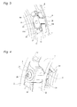
Fig. 3 is an enlarged view of an X part inFig. 1 . -
Fig. 4 is an enlarged view of a Y part inFig. 2 . -
Fig. 5 is an orthographic view seen from the inner side at the assembled state. -
Fig. 6 is an orthographic view of the composite disc rotor shown inFig. 1 seen from a radial direction at the assembled state. -
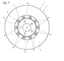
Fig. 7 is an orthographic view of the composite disc rotor shown inFig. 1 seen from the outer side at the assembled state. -
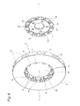
Fig. 8 is a perspective view of the composite disc rotor shown inFig. 1 seen from the inner side at a state where a disc main body and an attachment plate part are separated. -
Fig. 9 is a perspective view of the composite disc rotor shown inFig. 1 seen from the outer side at the state where the disc main body and the attachment plate part are separated. -
Fig. 10A is a perspective view of constitutional parts of a coupling unit of the composite disc rotor shown inFig. 1 seen from the inner side, andFig. 10B is a perspective view seen from the outer side. -
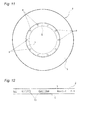
Fig. 11 is an orthographic view of the disc main body that is taken out, which is seen from the inner side. -
Fig. 12 is an orthographic view of the disc main body that is taken out, which is seen from the radial direction. -
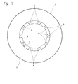
Fig. 13 is an orthographic view of the disc main body that is taken out, which is seen from the outer side. -
Fig. 14 is an orthographic view of a coupling bracket of the composite disc rotor shown inFig. 1 that is taken out, which is seen from the inner side. -
Fig. 15 is an orthographic view of the coupling bracket that is taken out, which is seen from a radial direction. -
Fig. 16 is an orthographic view of the coupling bracket that is taken out, which is seen from the outer side. -
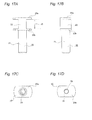
Fig. 17A is an orthographic view of a bobbin of the composite disc rotor shown inFig. 1 seen from the radial direction,Fig. 17B is an orthographic view of the bobbin seen from the circumferential direction,Fig. 17C is an orthographic view of the bobbin seen from the outer side andFig. 17D is an orthographic view of the bobbin seen from the inner side. -
Fig. 18A is an orthographic view of a clip of the composite disc rotor shown inFig. 1 seen from the radially outer side,Fig. 18B is an orthographic view of the clip seen from the inner side,Fig.18C is an orthographic view of the clip seen from the outer side andFig.18D is an orthographic view of the clip seen from the circumferential direction. -
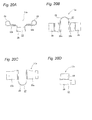
Fig. 19A is a perspective view of a clip according to a second embodiment of the invention, which is seen from the inner side, andFig. 19B is a perspective view of the clip according to the second embodiment of the invention, which is seen from the outer side. -
Fig. 20A is an orthographic view of the clip according to the second embodiment of the invention, which is seen from a radially outer side,Fig. 20B is an orthographic view of the clip seen from the inner side,Fig. 20C is an orthographic view of the clip seen from the outer side andFig. 20D is an orthographic view of the clip seen from the circumferential direction. -
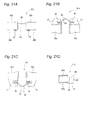
Fig. 21A is an orthographic view of a clip according to a reference example, which is seen from the radially outer side,Fig. 21B is an orthographic view of the clip seen from the inner side,Fig. 21C is an orthographic view of the clip seen from the outer side andFig. 21D is an orthographic view of the clip seen from the circumferential direction. -
Figs. 1 to 18 show a first embodiment of the invention. Acomposite disc rotor 1 of this embodiment has a discmain body 2, acoupling bracket 3 and a plurality of sets ofcoupling units 4. - An entire shape of the disc
main body 2 is a circular ring shape. The discmain body 2 is formed by a light material having sufficient strength, rigidity and wear resistance such as ceramic composite and carbon composite. Both side surfaces of the discmain body 2 in an axial direction perform as a pair offriction surfaces 5 to which pads are pushed upon braking. Also, acoupling part 6 is provided at an inner peripheral edge of the discmain body 2 so that it more extends in a radially inner side than the friction surfaces 5. Thecoupling part 6 has aflange part 7 and thick parts 8 (coupling portions). Theflange part 7 has an inward flange shape and is formed to continue over a whole circumference at an inner side part of an inner periphery of the discmain body 2. Her, the inner side is a central side in a width direction of a vehicle with being mounted to the vehicle. Also, the respectivethick parts 8 are formed at a plurality of equally-spaced positions in a circumferential direction (a plurality of circumferential positions) so that each thick part continues to an outer side surface of theflange part 7 in the width direction and the inner periphery of the discmain body 2. In the present embodiment, the thick parts are formed at 10 positions. The respectivethick parts 8 are formed withcoupling holes 9 at central portions thereof so that the respective coupling holes penetrate thethick parts 8 in an axial direction of the discmain body 2. Also, in the present embodiment,ventilation slots 10 through which both inner and outer circumferential surfaces of the discmain body 2 communicate with each other are formed at parts of the discmain body 2 between the respectivethick parts 8 in the circumferential direction. Thereby, thecomposite disc rotor 1 is a ventilated disc. - Also, an entire shape of the
coupling bracket 3 is a circular ring shape. Thecoupling bracket 3 is formed by performing the forging and necessary cutting operations for a light alloy material such as aluminum-based alloy and magnesium-based alloy. An outer diameter of thecoupling bracket 3 is slightly smaller than an inner diameter of the part of the discmain body 2 where the friction surfaces 5 are formed, and is sufficiently larger than a diameter of an inscribed circle of the respectivethick parts 8 of theflange part 7. Also, thecoupling bracket 3 is formed with astep part 11 at its radially central portion, and includes anattachment plate part 12 that is positioned at an inner diameter-side than thestep part 11 and acoupling plate part 13 that is positioned at an outer diameter-side than thestep part 11. Theattachment plate part 12 is formed with attachment holes 14 at a plurality of circumferentially equally-spaced positions in a radially central portion thereof. The attachment holes 14 are formed at five positions in the present embodiment. Bolts or studs (not shown) are inserted into the attachment holes 14 to couple and fix thecomposite disc rotor 1 to a rotating-side flange of a rolling bearing unit of a wheel support. Also, thecoupling plate part 13 is formed withnotches 15 at a plurality of circumferentially equally-spaced positions thereof. Each of thenotches 15 is opened to an outer peripheral edge of thecoupling bracket 3. Thenotches 15 are formed at 10 positions in the present embodiment. The number of thenotches 15 is the same as that of the coupling holes 9. Also, therespective coupling holes 9 are located at substantially central positions of therespective notches 15 in the radial direction at a state where the discmain body 2 and thecoupling bracket 2 are concentrically combined. In other words, the notched 15 are positioned at the plurality of circumferential positions of thethick parts 8. That is, therespective coupling holes 9 are matched with therespective notches 15 at a state where the discmain body 2 and thecoupling bracket 2 are combined. In this embodiment, a thickness of the parts of thecoupling plate part 13 where therespective notches 15 are formed is made to be larger than the other parts circumferentially spaced from the parts, thereby securing the compatibility between the lightweight object and the necessary strength and rigidity. - In the
composite disc rotor 1, therespective coupling units 4 are placed between the respectivethick parts 8. In other words, therespective coupling parts 4 are placed between therespective notches 15. Thereby, the discmain body 2 and thecoupling bracket 3 are combined so that the brake torque can be transmitted therebetween and the slight oscillating displacement can be made in a direction along which central axes thereof can be deviated. - Each of the
coupling units 4 includes abobbin 16, aclip 17, acoupling bolt 18. Further, awasher 19 through which thecoupling bolt 18 is inserted is provided for each of thecoupling units 4. - The
bobbin 16 is formed by performing the cutting operation for a metal material having sufficient strength and rigidity such as iron-based alloy, for example carbon steel, high-speed tool steel and stainless steel. The bobbin includes ahead part 20 and apipe part 21 in order from an axially inner side. A cross sectional shape of thehead part 20 in the axial direction of thedisc rotor 2 has a rounded rectangular shape. Thehead part 20 includes atorque receiving portion 22 and a pair ofprojections torque receiving portion 22 is the same as or slightly smaller than a width size of each of thenotches 15 formed at thecoupling bracket 3. Therefore, thetorque receiving portion 22 can be inserted into eachnotch 15 from the outer peripheral edge-side opening. After thetorque receiving portion 22 is inserted, it does not rattle. Also, theprojections torque receiving portion 22 in both circumferential directions. An interval D (refer toFig. 17 ) between theprojections Fig. 3 ) of the part of thecoupling bracket 3 where each of thenotches 15 are formed and two times of a thickness t (refer toFig. 18 ) of a metal plate configuring the clip 17 (D>T+2t). Also, thepipe part 21 can be fitted into eachcoupling hole 9 formed at each of thethick portions 8 of thecoupling part 6 of the discmain body 2 so as not to be ratted. Also, an inner diameter of thepipe part 21 is slightly larger than an outer diameter (screw thread diameter) of ascrew rod part 24 of thecoupling bolt 18 and is sufficiently smaller than a diameter of ahead part 25 of thecoupling bolt 18. Also, a central portion of thetorque receiving portion 22 is formed with ascrew hole 26 into which thescrew rod part 24 is screw-engaged and which is concentric with an inner periphery of thepipe part 21. Thecoupling hole 9 penetrates thehead part 25 and thepipe part 21. In addition, the coupling hole may be formed as a hole without being formed with thescrew rod part 24, and thecoupling bolt 18 may be screwed with a nut (not shown). - Also, the
clip 17 is integrally made by a stainless spring steel plate having elasticity and corrosion resistance. Theclip 17 includes aspacer portion 27 and a pair ofspring parts 28. Thespacer portion 27 has aconnection portion 29 and fourpressing portions 30b at a part held between thehead part 20 of thebobbin 16 and an inner surface and a peripheral part of eachnotch 15. Theconnection portion 29 is formed by folding back the spring steel plate into a U shape. The connection portion 29surrounds three sides, which are radially inner side and both circumferential sides, of thetorque receiving portion 22 of thebobbin 16, except for a radially outer side. Also, the respectivepressing portions 30b are formed by bending the opposed parts of theconnection portion 29 from both axial edges thereof in an opposite side to thetorque receiving portion 22 and are provided in a pair for each of the opposed parts. An interval between the respectivepressing portions 30b at a free state of theclip 17 is the same as or slightly smaller than the thickness T of the part of thecoupling bracket 3 where thenotches 15 are formed. Therefore, the respectivepressing portions 30b elastically interpose both circumferential sides of the part of thecoupling bracket 3 where thenotches 15 are formed from both axial sides. - In addition, both the
spring parts 28 are formed by folding back tip half parts of thepressing portions pressing portions 30b, which are positioned at an opposite side (inner side) to thepipe part 21, toward the head part 20 (toward the inner side). In this embodiment, thespring parts 28 have a central portion that is bent into a substantially partially cylindrical shape and a flat tip, respectively, and are opposed to thepressing portions spring parts 28 are held with being axially elastically compressed between theprojection 23a of thehead part 20 and both thepressing plates 30b at an assembled state of thecomposite disc rotor 1. An axial elastic force is applied between theprojection 23a and thecoupling bracket 3 having thebobbin 16 coupled and fixed thereto. - Also, in this embodiment, the
pressing portions 30a of the respectivepressing portions 30b, which are positioned at the pipe part 21-side (outer side). Thepressing portions 30a are provided withextension parts 31 extended therefrom in the radial direction to a more inner side than thehead part 20. Tips of therespective extension parts 31 are formed with engagingparts 32 that are engaged with radially inner end edges of the outer-side flange part 23b. Thus, theclip 17 is prevented from being displaced in the radially outer direction in eachnotch 15, irrespective of the centrifugal force that is applied when thecomposite disc rotor 1 rotates. - The
respective bobbins 16 are coupled and fixed to the discmain body 2 by therespective coupling bolts 18 and thecoupling bracket 3 is elastically supported to thehead parts 20 of therespective bobbins 16 by the respective clips 17. In a state where therespective coupling bolts 18 are inserted into the coupling holes 9 of thecoupling part 6 of the discmain body 2 from the outer side to the inner side, the respective tips thereof are screw-engaged and further tightened into the screw holes 26, 26 of therespective bobbins 16. Thereby, therespective bobbins 16 are coupled and fixed to the discmain body 2. Therespective bobbins 16 and therespective clips notches 15 of thecoupling bracket 3 before therespective bobbins 16 are coupled and fixed to the discmain body 2. Therefore, at a state where therespective bobbins 16 are coupled and fixed to the discmain body 2, the discmain body 2 and thecoupling bracket 3 are coupled so that the torque can be transmitted therebetween through therespective coupling units 4 and they can be slightly relatively displaced. - Since the
composite disc rotor 1 of this embodiment is configured and assembled as described above, it is possible to secure the sufficient durability and reliability and to reduce the number of parts while suppressing the manufacturing costs of the respective parts, thereby reducing the cost thereof. - That is, according to the
composite disc rotor 1 of the present embodiment, thetorque receiving portions 22 of thebobbins 16 of therespective coupling units 4 and therespective notches 15 are coupled, so that it is possible to transmit the sufficiently high torque between the discmain body 2 and thecoupling bracket 3. Also, each of thecoupling units 4 has a gap corresponding to a difference (D-T-2t) between the interval D between theprojections coupling bracket 3 forming eachnotch 15 and two times of the thickness t of the metal plate configuring theclip 17. When the moment in the direction of inclining the central axes of both the discmain body 2 and thecoupling bracket 3 is applied therebetween, both the discmain body 2 and thecoupling bracket 3 are relatively displaced while elastically deforming thespring parts 28 of theclips 17 provided in therespective coupling units 4. Hence, it is possible to prevent the excessive force from being applied to therespective coupling units 4 by the moment that is applied upon the braking. As a result, it is possible to secure the reliability and durability of thecomposite disc rotor 1 having therespective coupling units 4 incorporated thereto. Also, at a normal state, the coupling part between both the discmain body 2 and thecoupling bracket 3 does not rattle due to the elastic force of therespective spring parts 28. - Also, according to the
composite disc rotor 1 of this embodiment, therespective coupling units 4 do not have a part whose material yield is poor and manufacturing cost is high, such as the circular ring-shaped plate spring disclosed inPatent Document 5. Also, since therespective clips spacer portions 27 and thespring parts 28, it is possible to reduce the number of parts and to thus reduce the cost, which results from the easiness of the part manufacturing, the part management and the assembling operation. -
Figs. 19 and20 show a second embodiment of the present invention. Aclip 17a for the composite disc rotor of this embodiment includes a pair ofpressing portions 30b that is formed only at one axial edge of theconnection portion 29, excluding thepressing portions 30a from theclip 17 of the first embodiment refer toFigs. 10 and18 ). Also, a pair ofspring parts 28 is provided which continues from tip edges of both thepressing portions 30b. In a state where thecomposite disc rotor 1 includes theclips 17a, both thepressing portions 30b are contacted to one axial surface (inner surface) of both circumferential sides of each notch 15 (for example, refer toFigs. 8 ,9 ,14 and16 ) of thecoupling bracket 3. - According to the structure of the second embodiment, unlike the
clip 17 of the first embodiment, it is not necessary to strictly match the interval between the outerpressing portions 30a and the innerpressing portions 30b and the thickness T (refer toFig. 3 ) of the part of thecoupling bracket 3 where thenotches 15 are formed. That is, when the interval is larger than the thickness T, thecoupling bracket 3 rattles between the respectivepressing plates 30a. On the other hand, when the interval is smaller than the thickness T, it is difficult to mount theclips 17 to therespective notches 15. Compared to this, when theclip 17a of this embodiment is used, the coupling part 6 (refer toFigs. 1 and2 ) of thecoupling bracket 3 and the discmain body 2 does not rattle even when the size precision is not strictly regulated. - Also, although not shown, it may be possible to provide the
clip 17a shown inFigs. 19 and20 with the same engaging parts 32 (for example, refer toFigs. 10 and18 ) as those of theclip 17 of the first embodiment by extending thepressing portions - Since the other configurations and operations are the same as those of the first embodiment, except for the shape of the
clip 17a, the overlapping illustration and description are omitted. - According to the invention configured as described above, it is possible to provide a composite disc rotor capable of securing sufficient durability and reliability and reducing the number of parts while suppressing the manufacturing costs of respective parts, thereby reducing the cost thereof.
- First, according to the composite disc rotor of the invention, the disc main body and the coupling bracket can be coupled by each coupling unit so that the brake torque can be transmitted and the disc main body and the coupling bracket can be slightly relatively displaced based on the moment. Hence, it is possible to prevent the excessive force from being applied to the respective coupling units by the moment that is applied upon the braking and to secure the reliability and durability of the composite disc rotor having the respective coupling units incorporated thereto.
- Also, according to the composite disc rotor of the invention, the respective coupling units do not have a part whose material yield is poor and manufacturing cost is high, such as a circular ring-shaped plate spring disclosed in
Patent Document 5. Also, since each clip is provided with the spacer portion and the spring part, it is possible to reduce the number of parts and to thus reduce the cost, which results from the easiness of the part manufacturing, the part management and the assembling operation. - The features of the invention are the structure of each coupling unit for coupling the disc main body and the coupling bracket, which are separately configured. The materials and shapes of the disc main body and the coupling bracket are not limited to the shown structures and the various materials and shapes can be adopted.
- Also, if it doesn't care that the coupling part (refer to
Figs. 1 and2 , for example) of thecoupling bracket 3 and the discmain body 2 slightly rattle, it may be possible to configure the composite disc rotor by using aclip 17b that has the engagingparts 32 for preventing the diametrical deviation but does not have the spring parts 28 (for example, refer toFigs. 10 and18 ) for preventing the rattling.
Claims (9)
- A composite disc rotor comprising:a disc main body, having a ring shape, having a pair of friction surfaces which are opposite each other in an axial direction of the disc main body and to which pads are pushed upon braking, including a plurality of coupling portions at a plurality of circumferential positions of the disc main body, each of the coupling portions being disposed inner side in a radial direction of the disc main body and being formed with a coupling through hole;a coupling bracket, having a plurality of notches which are opened in an outer peripheral edge of the coupling bracket and disposed at the plurality of circumferential positions; anda plurality of coupling units, disposed at the plurality of circumferential positions, and each of which includes a bobbin including a head part and a pipe part, a clip and a coupling bolt, whereinthe head part includes a torque receiving portion inserted in each of the notches and a projection projected in a circumferential direction of the disc main body from an end of the torque receiving portion in the axial direction,the pipe part is extended from the head part and is fitted in the coupling through hole,each of the bobbins is formed with a through hole penetrating the head part and the pipe part,each of the clip includes a connecting portion between the torque receiving portion and a inner surface of each of the notches and a pressing portion extended from the connecting portion in the circumferential direction between the head part and the coupling bracket, andeach of the coupling bolts is inserted into each of the through holes of the bobbins to fix the coupling bracket to the coupling unit, so that a torque applied to the friction surfaces is transmitted to the coupling bracket via the bobbin.
- The composite disc rotor according to claim 1, wherein
the pressing portion includes a spring portion provided between the projection and the coupling bracket so as to urge the projection away from the coupling bracket in the axial direction. - The composite disc rotor according to claim 2, wherein
the connection portion surrounds three sides of the torque receiving portion of each bobbin and has a folded-back shape,
at least two pressing portions are extended from opposed positions of the connection portion, which are bent from at least one edge of the connection portion to an opposite side to the torque receiving portion, and
a part of each of the pressing portions is contacted to both circumferential side portions of each of the notches - The composite disc rotor according to claim 3, wherein
the spring portions are formed by folding back tip half parts of a pair of the pressing portions which are extended from an edge of the connection portion at a side of the head part in the axial direction, toward the head part, and
the spring portions are held between the head part and the pressing portions with being elastically compressed in the axial direction. - The composite disc rotor according to claim 3, wherein
the respective pressing portions are extended from four positions of the connecting portion,
two of the four positions are the opposed positions of the connection portion in the edge thereof at the side of the head part in the axial direction,
the other two of the four positions are opposed positions of the connection portion in an opposite edge thereof at an opposite side of the head part, and
the respective pressing portions interpose both circumferential sides of each notch of the coupling bracket from both axial sides. - The composite disc rotor according to claim 3, wherein
the respective pressing portions are extended from two positions of the connecting portion,
the two positions are the opposed positions of the connection portion in the edge thereof at the side of the head part in the axial direction, and
both the pressing portions are contacted to one axial surface of both circumferential sides of each notch. - The composite disc rotor according to claim 1, wherein
the pressing portion is extended from an edge of the connection portion at a side of the head part in the axial direction,
an extension part is extended inward in the radial direction from the pressing portion, and
the extension part includes an engaging part which is engaged with an inner end portion of the head part in the radial direction so as to restrict a displacement of the clip outward in the radial direction. - The composite disc rotor according to claim 1, wherein
at least a part of an inner surface of each of the through holes of the bobbins is formed with female screw, and
each of the coupling bolts is screwed with the female screw. - The composite disc rotor according to claim 1, wherein
each of the clips is integrally formed of a metal sheet having a resilience and corrosion resistance.
Applications Claiming Priority (1)
| Application Number | Priority Date | Filing Date | Title |
|---|---|---|---|
| JP2011275527A JP5791487B2 (en) | 2011-12-16 | 2011-12-16 | Composite type disc rotor |
Publications (3)
| Publication Number | Publication Date |
|---|---|
| EP2604883A2 true EP2604883A2 (en) | 2013-06-19 |
| EP2604883A3 EP2604883A3 (en) | 2018-04-04 |
| EP2604883B1 EP2604883B1 (en) | 2019-11-13 |
Family
ID=47602914
Family Applications (1)
| Application Number | Title | Priority Date | Filing Date |
|---|---|---|---|
| EP12197106.3A Active EP2604883B1 (en) | 2011-12-16 | 2012-12-14 | Composite disc rotor |
Country Status (4)
| Country | Link |
|---|---|
| US (1) | US9657794B2 (en) |
| EP (1) | EP2604883B1 (en) |
| JP (1) | JP5791487B2 (en) |
| CN (1) | CN103161855B (en) |
Cited By (3)
| Publication number | Priority date | Publication date | Assignee | Title |
|---|---|---|---|---|
| WO2019130188A1 (en) * | 2017-12-29 | 2019-07-04 | Freni Brembo S.P.A. | Brake disc for a disc brake and method |
| EP3910210A1 (en) * | 2020-05-15 | 2021-11-17 | ArvinMeritor Technology, LLC | Brake rotor |
| EP4105513A4 (en) * | 2020-02-12 | 2023-12-27 | Yantai Winhere Auto-Part Manufacturing Co., Ltd | Composite brake disc connecting assembly, and composite brake disc |
Families Citing this family (9)
| Publication number | Priority date | Publication date | Assignee | Title |
|---|---|---|---|---|
| US8671949B2 (en) | 2009-06-23 | 2014-03-18 | 3M Innovative Properties Company | Headgear-earwear assembly and a method of assembling same |
| EP2886902B1 (en) * | 2013-12-20 | 2016-12-07 | Brembo SGL Carbon Ceramic Brakes GmbH | Connecting means for brake disc assembly |
| WO2017049187A1 (en) * | 2015-09-16 | 2017-03-23 | Peformance Friction Corporation | Floating rotor disc with compressible retention ring fastener |
| US9964164B1 (en) | 2017-02-01 | 2018-05-08 | Consolidated Metco, Inc. | Disc brake tone ring |
| KR101921996B1 (en) * | 2017-03-27 | 2018-11-28 | 스톨츠 주식회사 | Brake system with adjustable tension |
| IT201700046888A1 (en) * | 2017-05-02 | 2018-11-02 | Campagnolo Srl | Bicycle brake disc assembly |
| DE102017116681B3 (en) * | 2017-07-24 | 2018-10-31 | Dr. Ing. H.C. F. Porsche Aktiengesellschaft | brake disc |
| DE102017121633A1 (en) * | 2017-09-19 | 2019-03-21 | Saf-Holland Gmbh | Multi-part brake rotor |
| KR20200079641A (en) * | 2018-12-26 | 2020-07-06 | 엘지이노텍 주식회사 | Motor |
Citations (5)
| Publication number | Priority date | Publication date | Assignee | Title |
|---|---|---|---|---|
| JP2004530848A (en) | 2001-06-13 | 2004-10-07 | フレニ・ブレンボ エス・ピー・エー | Disc for composite disc brake |
| EP1013956B1 (en) | 1998-12-23 | 2005-09-28 | DaimlerChrysler AG | Brake unit |
| JP2006528332A (en) | 2003-05-14 | 2006-12-14 | ダイムラークライスラー・アクチェンゲゼルシャフト | Brake disc with friction ring and connecting element |
| EP1970591B1 (en) | 2007-03-10 | 2010-02-17 | Audi Ag | Spring element for composite brake discs |
| EP1930617B1 (en) | 2006-12-09 | 2010-09-29 | Dr. Ing. h.c. F. Porsche AG | Spring for a composite brake disc and composite brake disc |
Family Cites Families (6)
| Publication number | Priority date | Publication date | Assignee | Title |
|---|---|---|---|---|
| DE19839763B4 (en) * | 1998-09-02 | 2006-06-29 | Knorr-Bremse Systeme für Nutzfahrzeuge GmbH | brake disc |
| US6604613B2 (en) * | 2000-03-24 | 2003-08-12 | Performance Friction Corporation | Brake hub with floating rotor and mounting flange allowing simplified rotor removal and replacement |
| DE102004048916A1 (en) * | 2004-10-06 | 2006-04-13 | Herbert Alber | Brake ring for high performance brake unit, comprising guiding sleeve suitable for positioning of additional spring element |
| JP4758852B2 (en) * | 2006-08-29 | 2011-08-31 | 本田技研工業株式会社 | Brake structure of wheel rotation device |
| SE531597C2 (en) * | 2007-10-05 | 2009-06-02 | Scania Cv Abp | Connection device for connection between a brake disc and a hub and method of mounting |
| KR101020548B1 (en) | 2008-09-03 | 2011-03-09 | 주식회사 데크 | Mounting unit and brake disk applied with the mounting unit |
-
2011
- 2011-12-16 JP JP2011275527A patent/JP5791487B2/en active Active
-
2012
- 2012-12-14 EP EP12197106.3A patent/EP2604883B1/en active Active
- 2012-12-14 US US13/714,824 patent/US9657794B2/en active Active
- 2012-12-17 CN CN201210549967.6A patent/CN103161855B/en active Active
Patent Citations (5)
| Publication number | Priority date | Publication date | Assignee | Title |
|---|---|---|---|---|
| EP1013956B1 (en) | 1998-12-23 | 2005-09-28 | DaimlerChrysler AG | Brake unit |
| JP2004530848A (en) | 2001-06-13 | 2004-10-07 | フレニ・ブレンボ エス・ピー・エー | Disc for composite disc brake |
| JP2006528332A (en) | 2003-05-14 | 2006-12-14 | ダイムラークライスラー・アクチェンゲゼルシャフト | Brake disc with friction ring and connecting element |
| EP1930617B1 (en) | 2006-12-09 | 2010-09-29 | Dr. Ing. h.c. F. Porsche AG | Spring for a composite brake disc and composite brake disc |
| EP1970591B1 (en) | 2007-03-10 | 2010-02-17 | Audi Ag | Spring element for composite brake discs |
Cited By (6)
| Publication number | Priority date | Publication date | Assignee | Title |
|---|---|---|---|---|
| WO2019130188A1 (en) * | 2017-12-29 | 2019-07-04 | Freni Brembo S.P.A. | Brake disc for a disc brake and method |
| EP3732382B1 (en) | 2017-12-29 | 2021-10-20 | BREMBO S.p.A. | Brake disc for a disc brake and method |
| US11268584B2 (en) | 2017-12-29 | 2022-03-08 | Freni Brembo S.P.A. | Brake disc for a disc brake and method |
| EP4105513A4 (en) * | 2020-02-12 | 2023-12-27 | Yantai Winhere Auto-Part Manufacturing Co., Ltd | Composite brake disc connecting assembly, and composite brake disc |
| EP3910210A1 (en) * | 2020-05-15 | 2021-11-17 | ArvinMeritor Technology, LLC | Brake rotor |
| US11629765B2 (en) | 2020-05-15 | 2023-04-18 | Arvinmeritor Technology, Llc | Brake rotor |
Also Published As
| Publication number | Publication date |
|---|---|
| JP5791487B2 (en) | 2015-10-07 |
| US20130153344A1 (en) | 2013-06-20 |
| US9657794B2 (en) | 2017-05-23 |
| CN103161855B (en) | 2016-06-08 |
| JP2013124758A (en) | 2013-06-24 |
| CN103161855A (en) | 2013-06-19 |
| EP2604883A3 (en) | 2018-04-04 |
| EP2604883B1 (en) | 2019-11-13 |
Similar Documents
| Publication | Publication Date | Title |
|---|---|---|
| EP2604883B1 (en) | Composite disc rotor | |
| EP2543905B1 (en) | Brake assembly having a mounting clip | |
| US7963375B2 (en) | Pole wheel which can be connected to a wheel hub of a motor vehicle | |
| US7871134B2 (en) | Wheel hub comprising axial recesses formed between the holes for lug bolts | |
| US8684144B2 (en) | Shaft brake disc, in particular for a rail vehicle | |
| JP5855398B2 (en) | Disc brake pad assembly | |
| US20120085603A1 (en) | Brake Disk | |
| EP2098383B1 (en) | Disc rotor pilot | |
| JP2008542108A (en) | Wheel carrier for vehicles with disc brake | |
| JP2016098912A (en) | Shim assembly for disc brake | |
| CN111173864A (en) | Composite brake disc connecting assembly and composite brake disc | |
| US10533619B2 (en) | Brake disk | |
| WO2004063592A1 (en) | Brake disc assembly | |
| CN111480020A (en) | Brake disc-hub connection | |
| EP3521651B1 (en) | Brake disc assembly | |
| EP3523551B1 (en) | A wheel brake arrangement | |
| US20190203784A1 (en) | Disc brake rotor having a damping element | |
| US7650975B2 (en) | Clutch disk arrangement for a multi-disk clutch | |
| US5601173A (en) | Liner support disc for supporting friction liners, especially for a motor vehicle | |
| JP2011207298A (en) | Inner ring of bearing device for wheel | |
| JP5085591B2 (en) | Combination shim plate for disc brake | |
| JP4932651B2 (en) | Opposite piston type disc brake | |
| JP2009133356A (en) | Floating caliper type disc brake | |
| US10920839B2 (en) | Disc brake rotor | |
| JP2007278334A (en) | Anti-rattling spring for disc brake |
Legal Events
| Date | Code | Title | Description |
|---|---|---|---|
| PUAI | Public reference made under article 153(3) epc to a published international application that has entered the european phase |
Free format text: ORIGINAL CODE: 0009012 |
|
| AK | Designated contracting states |
Kind code of ref document: A2 Designated state(s): AL AT BE BG CH CY CZ DE DK EE ES FI FR GB GR HR HU IE IS IT LI LT LU LV MC MK MT NL NO PL PT RO RS SE SI SK SM TR |
|
| AX | Request for extension of the european patent |
Extension state: BA ME |
|
| PUAL | Search report despatched |
Free format text: ORIGINAL CODE: 0009013 |
|
| AK | Designated contracting states |
Kind code of ref document: A3 Designated state(s): AL AT BE BG CH CY CZ DE DK EE ES FI FR GB GR HR HU IE IS IT LI LT LU LV MC MK MT NL NO PL PT RO RS SE SI SK SM TR |
|
| AX | Request for extension of the european patent |
Extension state: BA ME |
|
| RIC1 | Information provided on ipc code assigned before grant |
Ipc: F16D 65/12 20060101AFI20180227BHEP |
|
| STAA | Information on the status of an ep patent application or granted ep patent |
Free format text: STATUS: REQUEST FOR EXAMINATION WAS MADE |
|
| 17P | Request for examination filed |
Effective date: 20180913 |
|
| RBV | Designated contracting states (corrected) |
Designated state(s): AL AT BE BG CH CY CZ DE DK EE ES FI FR GB GR HR HU IE IS IT LI LT LU LV MC MK MT NL NO PL PT RO RS SE SI SK SM TR |
|
| GRAP | Despatch of communication of intention to grant a patent |
Free format text: ORIGINAL CODE: EPIDOSNIGR1 |
|
| STAA | Information on the status of an ep patent application or granted ep patent |
Free format text: STATUS: GRANT OF PATENT IS INTENDED |
|
| INTG | Intention to grant announced |
Effective date: 20190621 |
|
| GRAS | Grant fee paid |
Free format text: ORIGINAL CODE: EPIDOSNIGR3 |
|
| GRAA | (expected) grant |
Free format text: ORIGINAL CODE: 0009210 |
|
| STAA | Information on the status of an ep patent application or granted ep patent |
Free format text: STATUS: THE PATENT HAS BEEN GRANTED |
|
| AK | Designated contracting states |
Kind code of ref document: B1 Designated state(s): AL AT BE BG CH CY CZ DE DK EE ES FI FR GB GR HR HU IE IS IT LI LT LU LV MC MK MT NL NO PL PT RO RS SE SI SK SM TR |
|
| REG | Reference to a national code |
Ref country code: CH Ref legal event code: EP Ref country code: AT Ref legal event code: REF Ref document number: 1201980 Country of ref document: AT Kind code of ref document: T Effective date: 20191115 |
|
| REG | Reference to a national code |
Ref country code: DE Ref legal event code: R096 Ref document number: 602012065615 Country of ref document: DE |
|
| REG | Reference to a national code |
Ref country code: IE Ref legal event code: FG4D |
|
| REG | Reference to a national code |
Ref country code: NL Ref legal event code: MP Effective date: 20191113 |
|
| REG | Reference to a national code |
Ref country code: LT Ref legal event code: MG4D |
|
| PG25 | Lapsed in a contracting state [announced via postgrant information from national office to epo] |
Ref country code: PT Free format text: LAPSE BECAUSE OF FAILURE TO SUBMIT A TRANSLATION OF THE DESCRIPTION OR TO PAY THE FEE WITHIN THE PRESCRIBED TIME-LIMIT Effective date: 20200313 Ref country code: BG Free format text: LAPSE BECAUSE OF FAILURE TO SUBMIT A TRANSLATION OF THE DESCRIPTION OR TO PAY THE FEE WITHIN THE PRESCRIBED TIME-LIMIT Effective date: 20200213 Ref country code: FI Free format text: LAPSE BECAUSE OF FAILURE TO SUBMIT A TRANSLATION OF THE DESCRIPTION OR TO PAY THE FEE WITHIN THE PRESCRIBED TIME-LIMIT Effective date: 20191113 Ref country code: NL Free format text: LAPSE BECAUSE OF FAILURE TO SUBMIT A TRANSLATION OF THE DESCRIPTION OR TO PAY THE FEE WITHIN THE PRESCRIBED TIME-LIMIT Effective date: 20191113 Ref country code: SE Free format text: LAPSE BECAUSE OF FAILURE TO SUBMIT A TRANSLATION OF THE DESCRIPTION OR TO PAY THE FEE WITHIN THE PRESCRIBED TIME-LIMIT Effective date: 20191113 Ref country code: LV Free format text: LAPSE BECAUSE OF FAILURE TO SUBMIT A TRANSLATION OF THE DESCRIPTION OR TO PAY THE FEE WITHIN THE PRESCRIBED TIME-LIMIT Effective date: 20191113 Ref country code: PL Free format text: LAPSE BECAUSE OF FAILURE TO SUBMIT A TRANSLATION OF THE DESCRIPTION OR TO PAY THE FEE WITHIN THE PRESCRIBED TIME-LIMIT Effective date: 20191113 Ref country code: NO Free format text: LAPSE BECAUSE OF FAILURE TO SUBMIT A TRANSLATION OF THE DESCRIPTION OR TO PAY THE FEE WITHIN THE PRESCRIBED TIME-LIMIT Effective date: 20200213 Ref country code: ES Free format text: LAPSE BECAUSE OF FAILURE TO SUBMIT A TRANSLATION OF THE DESCRIPTION OR TO PAY THE FEE WITHIN THE PRESCRIBED TIME-LIMIT Effective date: 20191113 Ref country code: GR Free format text: LAPSE BECAUSE OF FAILURE TO SUBMIT A TRANSLATION OF THE DESCRIPTION OR TO PAY THE FEE WITHIN THE PRESCRIBED TIME-LIMIT Effective date: 20200214 Ref country code: LT Free format text: LAPSE BECAUSE OF FAILURE TO SUBMIT A TRANSLATION OF THE DESCRIPTION OR TO PAY THE FEE WITHIN THE PRESCRIBED TIME-LIMIT Effective date: 20191113 |
|
| PG25 | Lapsed in a contracting state [announced via postgrant information from national office to epo] |
Ref country code: IS Free format text: LAPSE BECAUSE OF FAILURE TO SUBMIT A TRANSLATION OF THE DESCRIPTION OR TO PAY THE FEE WITHIN THE PRESCRIBED TIME-LIMIT Effective date: 20200313 Ref country code: HR Free format text: LAPSE BECAUSE OF FAILURE TO SUBMIT A TRANSLATION OF THE DESCRIPTION OR TO PAY THE FEE WITHIN THE PRESCRIBED TIME-LIMIT Effective date: 20191113 Ref country code: RS Free format text: LAPSE BECAUSE OF FAILURE TO SUBMIT A TRANSLATION OF THE DESCRIPTION OR TO PAY THE FEE WITHIN THE PRESCRIBED TIME-LIMIT Effective date: 20191113 |
|
| PG25 | Lapsed in a contracting state [announced via postgrant information from national office to epo] |
Ref country code: AL Free format text: LAPSE BECAUSE OF FAILURE TO SUBMIT A TRANSLATION OF THE DESCRIPTION OR TO PAY THE FEE WITHIN THE PRESCRIBED TIME-LIMIT Effective date: 20191113 |
|
| PG25 | Lapsed in a contracting state [announced via postgrant information from national office to epo] |
Ref country code: EE Free format text: LAPSE BECAUSE OF FAILURE TO SUBMIT A TRANSLATION OF THE DESCRIPTION OR TO PAY THE FEE WITHIN THE PRESCRIBED TIME-LIMIT Effective date: 20191113 Ref country code: DK Free format text: LAPSE BECAUSE OF FAILURE TO SUBMIT A TRANSLATION OF THE DESCRIPTION OR TO PAY THE FEE WITHIN THE PRESCRIBED TIME-LIMIT Effective date: 20191113 Ref country code: RO Free format text: LAPSE BECAUSE OF FAILURE TO SUBMIT A TRANSLATION OF THE DESCRIPTION OR TO PAY THE FEE WITHIN THE PRESCRIBED TIME-LIMIT Effective date: 20191113 Ref country code: CZ Free format text: LAPSE BECAUSE OF FAILURE TO SUBMIT A TRANSLATION OF THE DESCRIPTION OR TO PAY THE FEE WITHIN THE PRESCRIBED TIME-LIMIT Effective date: 20191113 |
|
| REG | Reference to a national code |
Ref country code: CH Ref legal event code: PL |
|
| REG | Reference to a national code |
Ref country code: DE Ref legal event code: R097 Ref document number: 602012065615 Country of ref document: DE |
|
| REG | Reference to a national code |
Ref country code: AT Ref legal event code: MK05 Ref document number: 1201980 Country of ref document: AT Kind code of ref document: T Effective date: 20191113 |
|
| REG | Reference to a national code |
Ref country code: BE Ref legal event code: MM Effective date: 20191231 |
|
| PG25 | Lapsed in a contracting state [announced via postgrant information from national office to epo] |
Ref country code: SM Free format text: LAPSE BECAUSE OF FAILURE TO SUBMIT A TRANSLATION OF THE DESCRIPTION OR TO PAY THE FEE WITHIN THE PRESCRIBED TIME-LIMIT Effective date: 20191113 Ref country code: MC Free format text: LAPSE BECAUSE OF FAILURE TO SUBMIT A TRANSLATION OF THE DESCRIPTION OR TO PAY THE FEE WITHIN THE PRESCRIBED TIME-LIMIT Effective date: 20191113 Ref country code: SK Free format text: LAPSE BECAUSE OF FAILURE TO SUBMIT A TRANSLATION OF THE DESCRIPTION OR TO PAY THE FEE WITHIN THE PRESCRIBED TIME-LIMIT Effective date: 20191113 |
|
| PLBE | No opposition filed within time limit |
Free format text: ORIGINAL CODE: 0009261 |
|
| STAA | Information on the status of an ep patent application or granted ep patent |
Free format text: STATUS: NO OPPOSITION FILED WITHIN TIME LIMIT |
|
| 26N | No opposition filed |
Effective date: 20200814 |
|
| GBPC | Gb: european patent ceased through non-payment of renewal fee |
Effective date: 20200213 |
|
| PG25 | Lapsed in a contracting state [announced via postgrant information from national office to epo] |
Ref country code: FR Free format text: LAPSE BECAUSE OF NON-PAYMENT OF DUE FEES Effective date: 20200113 Ref country code: IE Free format text: LAPSE BECAUSE OF NON-PAYMENT OF DUE FEES Effective date: 20191214 Ref country code: LU Free format text: LAPSE BECAUSE OF NON-PAYMENT OF DUE FEES Effective date: 20191214 |
|
| PG25 | Lapsed in a contracting state [announced via postgrant information from national office to epo] |
Ref country code: BE Free format text: LAPSE BECAUSE OF NON-PAYMENT OF DUE FEES Effective date: 20191231 Ref country code: AT Free format text: LAPSE BECAUSE OF FAILURE TO SUBMIT A TRANSLATION OF THE DESCRIPTION OR TO PAY THE FEE WITHIN THE PRESCRIBED TIME-LIMIT Effective date: 20191113 Ref country code: CH Free format text: LAPSE BECAUSE OF NON-PAYMENT OF DUE FEES Effective date: 20191231 Ref country code: LI Free format text: LAPSE BECAUSE OF NON-PAYMENT OF DUE FEES Effective date: 20191231 Ref country code: SI Free format text: LAPSE BECAUSE OF FAILURE TO SUBMIT A TRANSLATION OF THE DESCRIPTION OR TO PAY THE FEE WITHIN THE PRESCRIBED TIME-LIMIT Effective date: 20191113 |
|
| PG25 | Lapsed in a contracting state [announced via postgrant information from national office to epo] |
Ref country code: IT Free format text: LAPSE BECAUSE OF FAILURE TO SUBMIT A TRANSLATION OF THE DESCRIPTION OR TO PAY THE FEE WITHIN THE PRESCRIBED TIME-LIMIT Effective date: 20191113 Ref country code: GB Free format text: LAPSE BECAUSE OF NON-PAYMENT OF DUE FEES Effective date: 20200213 |
|
| PG25 | Lapsed in a contracting state [announced via postgrant information from national office to epo] |
Ref country code: CY Free format text: LAPSE BECAUSE OF FAILURE TO SUBMIT A TRANSLATION OF THE DESCRIPTION OR TO PAY THE FEE WITHIN THE PRESCRIBED TIME-LIMIT Effective date: 20191113 |
|
| PG25 | Lapsed in a contracting state [announced via postgrant information from national office to epo] |
Ref country code: MT Free format text: LAPSE BECAUSE OF FAILURE TO SUBMIT A TRANSLATION OF THE DESCRIPTION OR TO PAY THE FEE WITHIN THE PRESCRIBED TIME-LIMIT Effective date: 20191113 Ref country code: HU Free format text: LAPSE BECAUSE OF FAILURE TO SUBMIT A TRANSLATION OF THE DESCRIPTION OR TO PAY THE FEE WITHIN THE PRESCRIBED TIME-LIMIT; INVALID AB INITIO Effective date: 20121214 |
|
| PG25 | Lapsed in a contracting state [announced via postgrant information from national office to epo] |
Ref country code: TR Free format text: LAPSE BECAUSE OF FAILURE TO SUBMIT A TRANSLATION OF THE DESCRIPTION OR TO PAY THE FEE WITHIN THE PRESCRIBED TIME-LIMIT Effective date: 20191113 |
|
| PG25 | Lapsed in a contracting state [announced via postgrant information from national office to epo] |
Ref country code: MK Free format text: LAPSE BECAUSE OF FAILURE TO SUBMIT A TRANSLATION OF THE DESCRIPTION OR TO PAY THE FEE WITHIN THE PRESCRIBED TIME-LIMIT Effective date: 20191113 |
|
| P01 | Opt-out of the competence of the unified patent court (upc) registered |
Effective date: 20230512 |
|
| PGFP | Annual fee paid to national office [announced via postgrant information from national office to epo] |
Ref country code: DE Payment date: 20231031 Year of fee payment: 12 |