EP1970591B1 - Spring element for composite brake discs - Google Patents
Spring element for composite brake discs Download PDFInfo
- Publication number
- EP1970591B1 EP1970591B1 EP07024574A EP07024574A EP1970591B1 EP 1970591 B1 EP1970591 B1 EP 1970591B1 EP 07024574 A EP07024574 A EP 07024574A EP 07024574 A EP07024574 A EP 07024574A EP 1970591 B1 EP1970591 B1 EP 1970591B1
- Authority
- EP
- European Patent Office
- Prior art keywords
- brake disc
- segments
- spring element
- ring
- bowl
- Prior art date
- Legal status (The legal status is an assumption and is not a legal conclusion. Google has not performed a legal analysis and makes no representation as to the accuracy of the status listed.)
- Active
Links
- 239000002131 composite material Substances 0.000 title claims description 12
- 239000000463 material Substances 0.000 claims description 5
- 238000013016 damping Methods 0.000 claims description 2
- 239000002184 metal Substances 0.000 claims 5
- 229910000831 Steel Inorganic materials 0.000 claims 1
- 238000004026 adhesive bonding Methods 0.000 claims 1
- 239000010959 steel Substances 0.000 claims 1
- 239000000919 ceramic Substances 0.000 description 3
- 229910010293 ceramic material Inorganic materials 0.000 description 3
- 229910001060 Gray iron Inorganic materials 0.000 description 2
- 229910000838 Al alloy Inorganic materials 0.000 description 1
- OKTJSMMVPCPJKN-UHFFFAOYSA-N Carbon Chemical compound [C] OKTJSMMVPCPJKN-UHFFFAOYSA-N 0.000 description 1
- 229910000639 Spring steel Inorganic materials 0.000 description 1
- XAGFODPZIPBFFR-UHFFFAOYSA-N aluminium Chemical compound [Al] XAGFODPZIPBFFR-UHFFFAOYSA-N 0.000 description 1
- 229910052782 aluminium Inorganic materials 0.000 description 1
- 229910052799 carbon Inorganic materials 0.000 description 1
- 238000010276 construction Methods 0.000 description 1
Images

Classifications
-
- F—MECHANICAL ENGINEERING; LIGHTING; HEATING; WEAPONS; BLASTING
- F16—ENGINEERING ELEMENTS AND UNITS; GENERAL MEASURES FOR PRODUCING AND MAINTAINING EFFECTIVE FUNCTIONING OF MACHINES OR INSTALLATIONS; THERMAL INSULATION IN GENERAL
- F16D—COUPLINGS FOR TRANSMITTING ROTATION; CLUTCHES; BRAKES
- F16D65/00—Parts or details
- F16D65/02—Braking members; Mounting thereof
- F16D65/12—Discs; Drums for disc brakes
- F16D65/123—Discs; Drums for disc brakes comprising an annular disc secured to a hub member; Discs characterised by means for mounting
-
- F—MECHANICAL ENGINEERING; LIGHTING; HEATING; WEAPONS; BLASTING
- F16—ENGINEERING ELEMENTS AND UNITS; GENERAL MEASURES FOR PRODUCING AND MAINTAINING EFFECTIVE FUNCTIONING OF MACHINES OR INSTALLATIONS; THERMAL INSULATION IN GENERAL
- F16D—COUPLINGS FOR TRANSMITTING ROTATION; CLUTCHES; BRAKES
- F16D65/00—Parts or details
- F16D65/02—Braking members; Mounting thereof
- F16D65/12—Discs; Drums for disc brakes
- F16D65/125—Discs; Drums for disc brakes characterised by the material used for the disc body
- F16D65/126—Discs; Drums for disc brakes characterised by the material used for the disc body the material being of low mechanical strength, e.g. carbon, beryllium; Torque transmitting members therefor
-
- F—MECHANICAL ENGINEERING; LIGHTING; HEATING; WEAPONS; BLASTING
- F16—ENGINEERING ELEMENTS AND UNITS; GENERAL MEASURES FOR PRODUCING AND MAINTAINING EFFECTIVE FUNCTIONING OF MACHINES OR INSTALLATIONS; THERMAL INSULATION IN GENERAL
- F16D—COUPLINGS FOR TRANSMITTING ROTATION; CLUTCHES; BRAKES
- F16D65/00—Parts or details
- F16D65/02—Braking members; Mounting thereof
- F16D2065/13—Parts or details of discs or drums
- F16D2065/1304—Structure
- F16D2065/1316—Structure radially segmented
-
- F—MECHANICAL ENGINEERING; LIGHTING; HEATING; WEAPONS; BLASTING
- F16—ENGINEERING ELEMENTS AND UNITS; GENERAL MEASURES FOR PRODUCING AND MAINTAINING EFFECTIVE FUNCTIONING OF MACHINES OR INSTALLATIONS; THERMAL INSULATION IN GENERAL
- F16D—COUPLINGS FOR TRANSMITTING ROTATION; CLUTCHES; BRAKES
- F16D65/00—Parts or details
- F16D65/02—Braking members; Mounting thereof
- F16D2065/13—Parts or details of discs or drums
- F16D2065/134—Connection
- F16D2065/1348—Connection resilient
-
- F—MECHANICAL ENGINEERING; LIGHTING; HEATING; WEAPONS; BLASTING
- F16—ENGINEERING ELEMENTS AND UNITS; GENERAL MEASURES FOR PRODUCING AND MAINTAINING EFFECTIVE FUNCTIONING OF MACHINES OR INSTALLATIONS; THERMAL INSULATION IN GENERAL
- F16D—COUPLINGS FOR TRANSMITTING ROTATION; CLUTCHES; BRAKES
- F16D65/00—Parts or details
- F16D65/02—Braking members; Mounting thereof
- F16D2065/13—Parts or details of discs or drums
- F16D2065/134—Connection
- F16D2065/1356—Connection interlocking
- F16D2065/1364—Connection interlocking with relative movement axially
-
- F—MECHANICAL ENGINEERING; LIGHTING; HEATING; WEAPONS; BLASTING
- F16—ENGINEERING ELEMENTS AND UNITS; GENERAL MEASURES FOR PRODUCING AND MAINTAINING EFFECTIVE FUNCTIONING OF MACHINES OR INSTALLATIONS; THERMAL INSULATION IN GENERAL
- F16D—COUPLINGS FOR TRANSMITTING ROTATION; CLUTCHES; BRAKES
- F16D65/00—Parts or details
- F16D65/02—Braking members; Mounting thereof
- F16D2065/13—Parts or details of discs or drums
- F16D2065/134—Connection
- F16D2065/1392—Connection elements
Definitions
- the invention relates to spring elements for composite brake discs.
- carbon ceramic brake discs are made in two-piece form with a ceramic cylindrical ring friction ring attached to a metallic pot.
- the metallic pot is in turn attached to a hub on the wheel shaft (hub) by means of screw fittings.
- For attachment of the friction ring to the pot usually combinations of screws and nuts are used, wherein the pressure surface between the screw head or the nut and the ceramic friction ring is enlarged by washers.
- biased washers spring rings, disc springs
- brake discs with a brake ring of gray cast iron material are made in two parts, wherein according to the patent EP 0 718 521 B1 Preferably, both the brake disk ring and the brake disk pot are made of a gray cast iron material.
- a composite brake disc 5 preferably comprises a brake disc ring 2 and a brake disc hub 3 and a spring ring 1, either according to Fig. 1 on the outside of the brake disk hub 3, that is, on the side remote from the brake disk ring 2, or between the brake disk chamber 3 and the brake disk ring 2 may be arranged, wherein the brake disk ring and the brake disk hub are interconnected by screws and nuts, not shown here.
- the portions 11 are facing away from the brake disk ring, and the portions 12 facing the brake disk ring (according to FIG Fig. 1 ) or directly on the brake disc ring.
- Another preferred embodiment is to provide such spring elements, which are each held by at least two of the screws 4 used as fastening elements and thereby are also against rotation.
- the spring element 1 alternately in succession at least four stages 13, so that in each case at least two sections 11, 11 'in the circumferential direction of an upper level 21 and the circumferentially adjacent portions 12, 12', 12 "to a lower level 22nd nestling, wherein the upper level 2) and the lower level 22 are parallel and have a vertical distance of 1 mm to 10 mm, and the fitting to the upper level sections 11 have holes 111 for mounting screws 4, and the ratio of the sum the arc lengths of the upper-level cling portions 11 to the sum of the arc lengths of the lower-cling portions 12 are from 1: 1 to 1: 5.
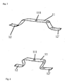
- the step between sections 11 and 12 can either be without a return be executed as in Fig. 2 represented, or with recesses in the form of a rounded "Z" according to the Fig. 3 , wherein each two adjacent stages are mirror images of each other.
- This embodiment offers the advantage that under a resilient load no thrust is exerted in the circumferential direction, which leads to a bulge in the sections 11 and 12.
- the spring element (1) forms a closed ring.
- the composite brake discs according to the invention provide an overall improved braking comfort, wherein the spring force by appropriate choice of material thickness, the step height, the execution of the stage and the type of spring steel used for the spring element individually on the intended use (the vehicle in question, the desired sporty or comfortable note) can be adjusted.
Landscapes
- Engineering & Computer Science (AREA)
- General Engineering & Computer Science (AREA)
- Mechanical Engineering (AREA)
- Braking Arrangements (AREA)
Description
Die Erfindung betrifft Federelemente für zusammengesetzte Bremsscheiben.The invention relates to spring elements for composite brake discs.
Üblicherweise werden Carbon-Keramik-Bremsscheiben in zweiteiliger Form ausgeführt, wobei ein keramischer zylinderringförmiger Reibring an einem metallischen Topf befestigt wird. Der metallische Topf wird seinerseits an einer Nabe an der Radwelle (Radnabe) mit Hilfe von Verschraubungen befestigt. Zur Befestigung des Reibringes an dem Topf werden üblicherweise Kombinationen von Schrauben und Muttern eingesetzt, wobei die Druckfläche zwischen dem Schraubenkopf oder der Mutter und dem keramischen Reibring durch Beilagscheiben vergrößert wird. Dabei werden in vorteilhafter Weise auch vorgespannte Beilagscheiben (Federringe, Tellerfedern) eingesetzt.Typically, carbon ceramic brake discs are made in two-piece form with a ceramic cylindrical ring friction ring attached to a metallic pot. The metallic pot is in turn attached to a hub on the wheel shaft (hub) by means of screw fittings. For attachment of the friction ring to the pot usually combinations of screws and nuts are used, wherein the pressure surface between the screw head or the nut and the ceramic friction ring is enlarged by washers. In this case, biased washers (spring rings, disc springs) are used in an advantageous manner.
Auch Bremsscheiben mit einem Bremsring aus Grauguss-Material werden zweiteilig ausgeführt, wobei gemäß der Patentschrift
Eine derartige Befestigung mit Schrauben und Muttern sowie Tellerfedern ist beispielsweise aus der Patentschrift
Aus der Patentanmeldung
Wegen der mechanischen Eigenschaften von keramischen Werkstoffen ist es erforderlich, die Auflagefläche der federnden Beilagscheiben so zu gestalten, dass die bei der Befestigung der Bremsscheibe und im Betrieb der Bremse entstehenden Drücke, die auf den keramischen Werkstoff wirken, so gering gehalten werden, dass keine Schädigung der keramischen Werkstoffe auftreten kann.Because of the mechanical properties of ceramic materials, it is necessary to design the bearing surface of the resilient washers so that the resulting in the attachment of the brake disc and during operation of the brake pressures acting on the ceramic material are kept so low that no damage the ceramic materials can occur.
Die Aufgabe wird durch die im Anspruch 1 beschriebenen Merkmale gelöst. Bevorzugte Ausführungsformen sind in den Unteransprüchen angegeben.The object is solved by the features described in
Die mit der vorliegenden Erfindung erzielten Vorteile sind eine Erleichterung der Montage dadurch, dass weniger federnde Teile, in einer bevorzugten Ausführungsform nur ein federndes Teil pro Bremsscheibe eingesetzt werden muss, eine wirksame axiale Dämpfung der zusammengesetzten Bremsscheibe, eine Reduktion der Flächenpressung im Auflagebereich, die besonders bei einem Bremsscheibentopf aus Aluminium oder Aluminiumlegierungen erwünscht ist, und ein radiales Spiel durch federnde Verformung des Federringes in radialer Richtung. Das Maß dieser zulässigen Verformung kann leicht durch geeignete Wahl von Federeigenschaften und Materialdicke sowie Ausführung der Stufen der Federelemente eingestellt werden.The advantages achieved by the present invention are facilitated by the fact that less resilient parts, in a preferred embodiment, only one resilient part per brake disc must be used, effective axial damping of the composite brake disc, a reduction of the surface pressure in the support area, the particular in a brake disk pot made of aluminum or aluminum alloys is desired, and a radial clearance by resilient deformation of the spring ring in the radial direction. The extent of this allowable deformation can be easily adjusted by a suitable choice of spring properties and material thickness and execution of the stages of the spring elements.
Ausführungsbeispiele der Erfindung werden durch die Zeichnungen dargestellt. Dabei zeigen
- Fig. 1 eine
- perspektivische Ansicht einer zusammengesetzten Bremsscheibe mit verbundenem Bremsscheibentopf und Bremsscheibenring sowie einem Federring, wobei der Federring auf die Außenseite des Bremsscheibentopfes aufgelegt ist,
- Fig.2
- einen Schnitt durch ein Federelement, bei dem die Stufe ohne Rücksprung ausgeführt ist, und
- Fig. 3
- einen Schnitt durch ein Federelement, bei dem Z-förmige Stufen mit Rücksprüngen ausgebildet sind.
- Fig. 1 a
- perspective view of a composite brake disc with a connected brake disc hub and brake disc ring and a spring ring, wherein the spring ring is placed on the outside of the brake disc hub,
- Fig.2
- a section through a spring element, in which the step is executed without a jump, and
- Fig. 3
- a section through a spring element, in which Z-shaped steps are formed with recesses.
Eine zusammengesetzte Bremsscheibe 5 umfasst in bevorzugter Weise einen Bremsscheibenring 2 und einen Bremsscheibentopf 3 sowie einen Federring 1, der entweder gemäß
Eine andere bevorzugte Ausführungsform ist, solche Federelemente vorzusehen, die jeweils durch mindestens zwei der als Befestigungselemente verwendeten Schrauben 4 gehalten werden und dadurch auch verdrehsicher sind.Another preferred embodiment is to provide such spring elements, which are each held by at least two of the
Erfindungsgemäß weist das Federelement 1 abwechselnd hintereinander mindestens vier Stufen 13 auf, derart dass sich jeweils mindestens zwei Abschnitte 11, 11' in Umfangsrichtung an eine obere Ebene 21 und jeweils die in Umfangsrichtung benachbarten Abschnitte 12, 12', 12" an eine untere Ebene 22 anschmiegen, wobei die obere Ebene 2) und die untere Ebene 22 parallel stehen und einen senkrechten Abstand von 1 mm bis 10 mm aufweisen, und die sich an die obere Ebene anschmiegenden Abschnitte 11 weisen Bohrungen 111 für Befestigungsschrauben 4 auf, und das Verhältnis der Summe der Bogenlängen der sich an die obere Ebene anschmiegenden Abschnitte 11 zu der Summe der Bogenlängen der sich an die untere Ebene anschmiegenden Abschnitte 12 beträgt von 1:1 bis 1:5.According to the invention, the
Die Stufe zwischen den Abschnitten 11 und 12 kann entweder ohne Rücksprung ausgeführt sein, wie in
Das Federelement (1) bildet einen geschlossenen Ring.The spring element (1) forms a closed ring.
Die zusammengesetzten Bremsscheiben gemäß der Erfindung bieten insgesamt einen verbesserten Bremskomfort, wobei die Federkraft durch geeignete Wahl der Materialstärke, der Stufenhöhe, der Ausführung der Stufe und der Art des verwendeten Federstahls für das Federelement individuell auf den Verwendungszweck (das betreffende Fahrzeug, die gewünschte sportliche oder komfortable Note) eingestellt werden kann.The composite brake discs according to the invention provide an overall improved braking comfort, wherein the spring force by appropriate choice of material thickness, the step height, the execution of the stage and the type of spring steel used for the spring element individually on the intended use (the vehicle in question, the desired sporty or comfortable note) can be adjusted.
Claims (6)
- Composite brake disc (5) comprising a brake disc ring (2) and a metal brake disc bowl (3) and at least one spring element (1) for axial damping and for attaching the brake disc ring (2) to the metal brake disc bowl (3), characterized in that the spring element (1) forms a closed ring and has at least four steps (13) in it that successively alternate so that each segment of one set of at least two segments (11, 11') in the circumferential direction lies on an upper plane (21) and each of the adjacent segments (12, 12', 12") in the circumferential direction lies on a lower plane (22), the spring element (1) bearing on the metal brake disc bowl (3) through the segments lying on the lower plane, and the upper (21) and lower (22) planes lying parallel and spaced perpendicularly 1 mm to 10 mm apart; in that the segments (11) lying on the upper plane have holes (111) for fixing screws (4); and in that the ratio of the sum of the lengths of arc of the segments (11) lying on the upper plane to the sum of the lengths of arc of the segments (12) lying on the lower plane is from 1:1 to 1:5.
- Composite brake disc (5) according to Claim 1, characterized in that the material of the spring element is steel.
- Composite brake disc (5) according to Claim 1, characterized in that the steps (13) in the spring element have a Z-shaped profile, with every two adjacent Z-shaped steps (13, 13') formed as a mirror-inverted pair.
- Composite brake disc (5) according to Claim 1, characterized in that the spring element (1) bears on the metal brake disc bowl (3) through the segments lying on the lower plane, and fixing screws (4) are passed through the holes (111), through holes or gaps (31) in the metal brake disc bowl (3) and through holes or gaps (21) in the brake disc ring (2) and are fixed with a nut or fastener (42) on the side of the brake disc ring (2) facing away from the screw head (41) so as to exert a force on the segment (11) of the spring element (1) in the direction towards the brake disc ring (2).
- Composite brake disc (5) according to Claim 4, characterized in that a least a part of the segments (12) is attached to the brake disc bowl (3).
- Composite brake disc (5) according to Claim 5, characterized in that the segments (12) are attached to the brake disc bowl (3) by gluing and/or screwing.
Applications Claiming Priority (1)
| Application Number | Priority Date | Filing Date | Title |
|---|---|---|---|
| DE102007011743A DE102007011743A1 (en) | 2007-03-10 | 2007-03-10 | Spring element for composite brake discs |
Publications (2)
| Publication Number | Publication Date |
|---|---|
| EP1970591A1 EP1970591A1 (en) | 2008-09-17 |
| EP1970591B1 true EP1970591B1 (en) | 2010-02-17 |
Family
ID=39441833
Family Applications (1)
| Application Number | Title | Priority Date | Filing Date |
|---|---|---|---|
| EP07024574A Active EP1970591B1 (en) | 2007-03-10 | 2007-12-19 | Spring element for composite brake discs |
Country Status (3)
| Country | Link |
|---|---|
| US (1) | US20080271965A1 (en) |
| EP (1) | EP1970591B1 (en) |
| DE (2) | DE102007011743A1 (en) |
Cited By (1)
| Publication number | Priority date | Publication date | Assignee | Title |
|---|---|---|---|---|
| EP2604883A2 (en) | 2011-12-16 | 2013-06-19 | Akebono Brake Industry Co., Ltd. | Composite disc rotor |
Families Citing this family (6)
| Publication number | Priority date | Publication date | Assignee | Title |
|---|---|---|---|---|
| US8950556B2 (en) | 2011-03-31 | 2015-02-10 | Gunite Corporation | Disk brake hub assembly |
| US9566957B2 (en) * | 2011-03-31 | 2017-02-14 | Gunite Corporation | Disk brake hub assembly |
| US9897154B2 (en) | 2011-03-31 | 2018-02-20 | Gunite Corporation | Disk brake hub assembly |
| DE102011084946A1 (en) | 2011-10-21 | 2013-04-25 | Bayerische Motoren Werke Aktiengesellschaft | Automotive brake disc |
| EP2740961B1 (en) * | 2012-12-10 | 2017-02-15 | Brembo SGL Carbon Ceramic Brakes GmbH | Connecting means for brake disc |
| DE102013215997B4 (en) | 2013-08-13 | 2022-06-30 | Bayerische Motoren Werke Aktiengesellschaft | Brake disc for a vehicle |
Family Cites Families (10)
| Publication number | Priority date | Publication date | Assignee | Title |
|---|---|---|---|---|
| US3754624A (en) * | 1971-09-17 | 1973-08-28 | Bendix Corp | Flexible key for disc brake |
| US4049085A (en) * | 1976-08-10 | 1977-09-20 | Safety Racing Equipment, Incorporated | Caliper brake with assembly for rotor attachment to hub |
| DE4446017C2 (en) | 1994-12-22 | 1999-07-08 | Porsche Ag | Two-piece brake disc, especially internally ventilated brake disc |
| GB2340564A (en) | 1998-08-15 | 2000-02-23 | T & N Technology Ltd | Disc brake |
| DE10046705C1 (en) * | 2000-09-21 | 2002-07-25 | Knorr Bremse Systeme | Brake disc / hub connection for vehicle disc brakes |
| EP1395760B1 (en) * | 2001-06-13 | 2004-08-25 | Freni Brembo S.p.A. | Composite disk for a disk brake |
| US7104368B2 (en) * | 2002-01-14 | 2006-09-12 | Freni Brembo S.P.A | Disk-brake disk |
| DE20207605U1 (en) * | 2002-05-15 | 2003-01-16 | Franke, Edgar, 72275 Alpirsbach | Suspension mat to support seats |
| US7374023B2 (en) * | 2002-05-27 | 2008-05-20 | Yutaka Giken Co., Ltd. | Floating-type brake disk |
| US7654365B2 (en) * | 2006-02-21 | 2010-02-02 | Lamb Roger A | Two-piece floating disc brake assembly |
-
2007
- 2007-03-10 DE DE102007011743A patent/DE102007011743A1/en not_active Withdrawn
- 2007-12-19 DE DE502007002859T patent/DE502007002859D1/en active Active
- 2007-12-19 EP EP07024574A patent/EP1970591B1/en active Active
-
2008
- 2008-03-10 US US12/045,279 patent/US20080271965A1/en not_active Abandoned
Cited By (1)
| Publication number | Priority date | Publication date | Assignee | Title |
|---|---|---|---|---|
| EP2604883A2 (en) | 2011-12-16 | 2013-06-19 | Akebono Brake Industry Co., Ltd. | Composite disc rotor |
Also Published As
| Publication number | Publication date |
|---|---|
| EP1970591A1 (en) | 2008-09-17 |
| DE502007002859D1 (en) | 2010-04-01 |
| DE102007011743A1 (en) | 2008-09-11 |
| US20080271965A1 (en) | 2008-11-06 |
Similar Documents
| Publication | Publication Date | Title |
|---|---|---|
| EP1970591B1 (en) | Spring element for composite brake discs | |
| DE60105206T2 (en) | WASHER OF COMPOSITE MATERIAL FOR A DISC BRAKE | |
| EP1819935B1 (en) | Caliper for a disk brake | |
| EP1930617B1 (en) | Spring for a composite brake disc and composite brake disc | |
| EP2028387B1 (en) | Brake discs/collar connection | |
| EP2553290A1 (en) | Brake disc | |
| EP0872659B1 (en) | Brake disc, in particular internally ventilated brake disc | |
| DE19830666B4 (en) | Brake disc, in particular for a motor vehicle | |
| DE2106208C3 (en) | ||
| DE102008018326B4 (en) | Fastening device for a friction ring of a brake unit | |
| DE19807184C1 (en) | Brake disk for commercial vehicle | |
| EP0912839A2 (en) | Brake disk unit | |
| EP1747385B1 (en) | Brake disk/hub assembly with displaceable brake disks | |
| DE102008014857B4 (en) | Brake disc / hub connection | |
| DE10148681B4 (en) | Brake disc for a disc brake | |
| WO2011085748A1 (en) | Retaining arrangement for retaining a brake disk on a wheel hub of a motor vehicle | |
| DE102013001322B4 (en) | Support member and friction ring of a brake disc, brake disc and method for producing a brake disc | |
| DE102011010866B4 (en) | Brake discs / hub connection and brake disc | |
| DE10221455A1 (en) | Vehicle wheel hub has bearer sector of friction body clamped axially against hub by wheel bearing | |
| DE19652106C2 (en) | Clutch disc for friction clutches | |
| EP1645768B1 (en) | Carbon ceramic brake disc | |
| DE29823371U1 (en) | Two-piece brake disc | |
| WO2014194896A1 (en) | Wheel bearing having an axial stabilizing ring | |
| DE10107983A1 (en) | Internally ventilated, cast brake disc | |
| EP1967756B1 (en) | Wheel bolt bushing for a ceramic brake disc |
Legal Events
| Date | Code | Title | Description |
|---|---|---|---|
| PUAI | Public reference made under article 153(3) epc to a published international application that has entered the european phase |
Free format text: ORIGINAL CODE: 0009012 |
|
| AK | Designated contracting states |
Kind code of ref document: A1 Designated state(s): AT BE BG CH CY CZ DE DK EE ES FI FR GB GR HU IE IS IT LI LT LU LV MC MT NL PL PT RO SE SI SK TR |
|
| AX | Request for extension of the european patent |
Extension state: AL BA HR MK RS |
|
| 17P | Request for examination filed |
Effective date: 20090317 |
|
| 17Q | First examination report despatched |
Effective date: 20090417 |
|
| AKX | Designation fees paid |
Designated state(s): DE FR GB IT |
|
| GRAP | Despatch of communication of intention to grant a patent |
Free format text: ORIGINAL CODE: EPIDOSNIGR1 |
|
| GRAS | Grant fee paid |
Free format text: ORIGINAL CODE: EPIDOSNIGR3 |
|
| GRAA | (expected) grant |
Free format text: ORIGINAL CODE: 0009210 |
|
| AK | Designated contracting states |
Kind code of ref document: B1 Designated state(s): DE FR GB IT |
|
| REG | Reference to a national code |
Ref country code: GB Ref legal event code: FG4D Free format text: NOT ENGLISH |
|
| REF | Corresponds to: |
Ref document number: 502007002859 Country of ref document: DE Date of ref document: 20100401 Kind code of ref document: P |
|
| PLBE | No opposition filed within time limit |
Free format text: ORIGINAL CODE: 0009261 |
|
| STAA | Information on the status of an ep patent application or granted ep patent |
Free format text: STATUS: NO OPPOSITION FILED WITHIN TIME LIMIT |
|
| 26N | No opposition filed |
Effective date: 20101118 |
|
| PG25 | Lapsed in a contracting state [announced via postgrant information from national office to epo] |
Ref country code: IT Free format text: LAPSE BECAUSE OF NON-PAYMENT OF DUE FEES Effective date: 20101219 |
|
| REG | Reference to a national code |
Ref country code: FR Ref legal event code: PLFP Year of fee payment: 9 |
|
| REG | Reference to a national code |
Ref country code: FR Ref legal event code: PLFP Year of fee payment: 10 |
|
| REG | Reference to a national code |
Ref country code: FR Ref legal event code: PLFP Year of fee payment: 11 |
|
| P01 | Opt-out of the competence of the unified patent court (upc) registered |
Effective date: 20230529 |
|
| PGFP | Annual fee paid to national office [announced via postgrant information from national office to epo] |
Ref country code: GB Payment date: 20231218 Year of fee payment: 17 |
|
| PGFP | Annual fee paid to national office [announced via postgrant information from national office to epo] |
Ref country code: IT Payment date: 20231227 Year of fee payment: 17 Ref country code: FR Payment date: 20231220 Year of fee payment: 17 Ref country code: DE Payment date: 20231231 Year of fee payment: 17 |