EP2604823A2 - Method and system for separating CO2 from N2 and O2 in a turbine engine system - Google Patents
Method and system for separating CO2 from N2 and O2 in a turbine engine system Download PDFInfo
- Publication number
- EP2604823A2 EP2604823A2 EP12195675.9A EP12195675A EP2604823A2 EP 2604823 A2 EP2604823 A2 EP 2604823A2 EP 12195675 A EP12195675 A EP 12195675A EP 2604823 A2 EP2604823 A2 EP 2604823A2
- Authority
- EP
- European Patent Office
- Prior art keywords
- gases
- mixture
- directing
- compressor
- accordance
- Prior art date
- Legal status (The legal status is an assumption and is not a legal conclusion. Google has not performed a legal analysis and makes no representation as to the accuracy of the status listed.)
- Withdrawn
Links
Images

Classifications
-
- F—MECHANICAL ENGINEERING; LIGHTING; HEATING; WEAPONS; BLASTING
- F02—COMBUSTION ENGINES; HOT-GAS OR COMBUSTION-PRODUCT ENGINE PLANTS
- F02C—GAS-TURBINE PLANTS; AIR INTAKES FOR JET-PROPULSION PLANTS; CONTROLLING FUEL SUPPLY IN AIR-BREATHING JET-PROPULSION PLANTS
- F02C3/00—Gas-turbine plants characterised by the use of combustion products as the working fluid
- F02C3/20—Gas-turbine plants characterised by the use of combustion products as the working fluid using a special fuel, oxidant, or dilution fluid to generate the combustion products
-
- F—MECHANICAL ENGINEERING; LIGHTING; HEATING; WEAPONS; BLASTING
- F01—MACHINES OR ENGINES IN GENERAL; ENGINE PLANTS IN GENERAL; STEAM ENGINES
- F01K—STEAM ENGINE PLANTS; STEAM ACCUMULATORS; ENGINE PLANTS NOT OTHERWISE PROVIDED FOR; ENGINES USING SPECIAL WORKING FLUIDS OR CYCLES
- F01K23/00—Plants characterised by more than one engine delivering power external to the plant, the engines being driven by different fluids
- F01K23/02—Plants characterised by more than one engine delivering power external to the plant, the engines being driven by different fluids the engine cycles being thermally coupled
- F01K23/06—Plants characterised by more than one engine delivering power external to the plant, the engines being driven by different fluids the engine cycles being thermally coupled combustion heat from one cycle heating the fluid in another cycle
- F01K23/10—Plants characterised by more than one engine delivering power external to the plant, the engines being driven by different fluids the engine cycles being thermally coupled combustion heat from one cycle heating the fluid in another cycle with exhaust fluid of one cycle heating the fluid in another cycle
-
- F—MECHANICAL ENGINEERING; LIGHTING; HEATING; WEAPONS; BLASTING
- F02—COMBUSTION ENGINES; HOT-GAS OR COMBUSTION-PRODUCT ENGINE PLANTS
- F02C—GAS-TURBINE PLANTS; AIR INTAKES FOR JET-PROPULSION PLANTS; CONTROLLING FUEL SUPPLY IN AIR-BREATHING JET-PROPULSION PLANTS
- F02C3/00—Gas-turbine plants characterised by the use of combustion products as the working fluid
- F02C3/34—Gas-turbine plants characterised by the use of combustion products as the working fluid with recycling of part of the working fluid, i.e. semi-closed cycles with combustion products in the closed part of the cycle
-
- F—MECHANICAL ENGINEERING; LIGHTING; HEATING; WEAPONS; BLASTING
- F05—INDEXING SCHEMES RELATING TO ENGINES OR PUMPS IN VARIOUS SUBCLASSES OF CLASSES F01-F04
- F05D—INDEXING SCHEME FOR ASPECTS RELATING TO NON-POSITIVE-DISPLACEMENT MACHINES OR ENGINES, GAS-TURBINES OR JET-PROPULSION PLANTS
- F05D2260/00—Function
- F05D2260/20—Heat transfer, e.g. cooling
- F05D2260/205—Cooling fluid recirculation, i.e. after cooling one or more components is the cooling fluid recovered and used elsewhere for other purposes
-
- F—MECHANICAL ENGINEERING; LIGHTING; HEATING; WEAPONS; BLASTING
- F05—INDEXING SCHEMES RELATING TO ENGINES OR PUMPS IN VARIOUS SUBCLASSES OF CLASSES F01-F04
- F05D—INDEXING SCHEME FOR ASPECTS RELATING TO NON-POSITIVE-DISPLACEMENT MACHINES OR ENGINES, GAS-TURBINES OR JET-PROPULSION PLANTS
- F05D2260/00—Function
- F05D2260/60—Fluid transfer
- F05D2260/61—Removal of CO2
-
- Y—GENERAL TAGGING OF NEW TECHNOLOGICAL DEVELOPMENTS; GENERAL TAGGING OF CROSS-SECTIONAL TECHNOLOGIES SPANNING OVER SEVERAL SECTIONS OF THE IPC; TECHNICAL SUBJECTS COVERED BY FORMER USPC CROSS-REFERENCE ART COLLECTIONS [XRACs] AND DIGESTS
- Y02—TECHNOLOGIES OR APPLICATIONS FOR MITIGATION OR ADAPTATION AGAINST CLIMATE CHANGE
- Y02E—REDUCTION OF GREENHOUSE GAS [GHG] EMISSIONS, RELATED TO ENERGY GENERATION, TRANSMISSION OR DISTRIBUTION
- Y02E20/00—Combustion technologies with mitigation potential
- Y02E20/16—Combined cycle power plant [CCPP], or combined cycle gas turbine [CCGT]
- Y02E20/18—Integrated gasification combined cycle [IGCC], e.g. combined with carbon capture and storage [CCS]
-
- Y—GENERAL TAGGING OF NEW TECHNOLOGICAL DEVELOPMENTS; GENERAL TAGGING OF CROSS-SECTIONAL TECHNOLOGIES SPANNING OVER SEVERAL SECTIONS OF THE IPC; TECHNICAL SUBJECTS COVERED BY FORMER USPC CROSS-REFERENCE ART COLLECTIONS [XRACs] AND DIGESTS
- Y02—TECHNOLOGIES OR APPLICATIONS FOR MITIGATION OR ADAPTATION AGAINST CLIMATE CHANGE
- Y02E—REDUCTION OF GREENHOUSE GAS [GHG] EMISSIONS, RELATED TO ENERGY GENERATION, TRANSMISSION OR DISTRIBUTION
- Y02E20/00—Combustion technologies with mitigation potential
- Y02E20/34—Indirect CO2mitigation, i.e. by acting on non CO2directly related matters of the process, e.g. pre-heating or heat recovery
Definitions
- the field of the invention relates generally to turbine engine systems, and more particularly, to turbine engine systems in power generation plants.
- Turbine engines produce mechanical energy using a working fluid supplied to the engines. More specifically, in known turbine engines, the working fluid may be air that is compressed and delivered, along with fuel and oxygen, to a combustor, wherein the fuel-air mixture is ignited. As the fuel-air mixture bums, its energy is released into the working fluid as heat. The temperature rise causes a corresponding increase in the pressure of the working fluid, and following combustion, the working fluid expands as it is discharged from the combustor downstream towards at least one turbine. As the working fluid flows past each turbine, the turbine is rotated and converts the heat energy to mechanical energy in the form of thrust or shaft power connected to a generator.
- the working fluid may be air that is compressed and delivered, along with fuel and oxygen, to a combustor, wherein the fuel-air mixture is ignited. As the fuel-air mixture bums, its energy is released into the working fluid as heat. The temperature rise causes a corresponding increase in the pressure of the working fluid, and following combustion, the working fluid expands as it is discharged
- NOx oxides of nitrogen
- HC unburned hydrocarbons
- CO carbon monoxide
- CO 2 carbon dioxide
- At least some known gas turbine engines operate with reduced combustion temperatures and/or Selective Catalytic Reduction (SCR) equipment.
- SCR Selective Catalytic Reduction
- any benefits gained through using known SCR equipment may be outweighed by the cost of the equipment and/or the cost of disposing the NOx.
- an oxidation catalyst may be used.
- at least some known gas turbine engines channel turbine exhaust through a gas separation unit to separate CO 2 from nitrogen (N 2 ), the major component when using air as the working fluid, and at least one CO 2 compressor. Again however, the benefits gained through the use of such equipment may be outweighed by the costs of the equipment.
- a method of separating carbon dioxide (CO 2 ) from nitrogen (N 2 ) and oxygen (O 2 ) in a turbine engine system includes a first compressor coupled to a turbine expander by a rotatable shaft, and a combustor coupled in flow communication to the compressor and the first turbine.
- the method includes directing an air stream into an air separation unit (ASU), separating N 2 from the air stream in the ASU to form an oxygen (O 2 ) rich air stream, and directing the O 2 rich air stream to the combustor to mix with a fuel for combustion forming hot combustion gases, containing O 2 and CO 2 , which are used to rotate the turbine.
- ASU air separation unit
- the method also includes directing turbine exhaust gases to a heat recovery steam generator (HRSG) to create steam, directing exhaust from the HRSG to a condenser to separate water from a mixture of O 2 and CO 2 gases, and directing the mixture of O 2 and CO 2 gases to a separation system, where the CO 2 is separated from the O 2 gases and removed from the separation system.
- HRSG heat recovery steam generator
- a system in separating CO 2 and N 2 in a turbine engine apparatus includes an air separation unit (ASU) for separating N 2 from an air stream that forms an oxygen (O 2 ) rich air stream, a heat recovery steam generator (HRSG), and a condenser to separate water from a mixture of O 2 and CO 2 gases from the HRSG.
- ASU air separation unit
- HRSG heat recovery steam generator
- condenser to separate water from a mixture of O 2 and CO 2 gases from the HRSG.
- the system also includes a separation system where the CO 2 is separated from the O 2 gases and removed from the separation system.
- Novel methods of producing a carbon dioxide (CO 2 ) rich stream and a nitrogen (N 2 ) rich stream from combustion of a hydrocarbon fuel source (natural gas, oil, coal) are disclosed.
- Applications of the novel methods involve electricity production, enhanced oil recovery, carbon capture, and sequestration.
- the methods disclosed provide separation of CO 2 and N 2 gases which are products of a combustion process. Methods and systems for separating N 2 and CO 2 from the working air and/or exhaust in turbine engine systems in power generation plants are described below in detail.
- oxygen (O 2 ) is separated from a CO 2 and O 2 mixture in the exhaust of the turbine engine system, and may be recycled back to the oxyfuel combuster of the turbine engine system. Removing the N 2 from the working air reduces NOx emissions.
- the CO 2 removed from the exhaust may be sequestered for use in enhanced oil recovery.
- a stream of removed CO 2 may contain no O 2 or less that 1 percent of O 2 .
- Advantages of the methods and systems described below include removing O 2 from a CO 2 stream with lower energy and lower costs than known methods. With O 2 removed from a CO 2 stream, the CO 2 stream may be used for injection in an oil well for enhanced oil recovery. Streams of CO 2 that do include O 2 can be detrimental to oil recovery because of the reactivity of O 2 .
- advantages of the methods and systems may include improved flexibility of operation of a power generation plant, a safer power generation plant because of reduced CO emissions and a reduced need for the use of CO oxidation catalysts.
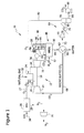
- FIG. 1 is a schematic illustration of an exemplary combined-cycle power generation plant 10 that includes a gas turbine engine 12.
- Gas turbine engine 12 includes a compressor 14 that is coupled to a turbine expander 16 (also referred to in the art as a "turbine") via a rotatable shaft 18.
- Compressor 14 receives air at locally atmospheric pressures and temperatures.
- Turbine expander 16 is coupled to a first electrical generator 20 via a first rotor 22.
- Gas turbine engine 12 also includes a combustor 24 coupled in flow communication with compressor 14.
- Combustor 24 receives at least a portion of recirculated CO 2 compressed by compressor 14 via a conduit 26.
- an air separation unit (ASU) 28 is coupled in flow communication with combustor 24 by a conduit 27.
- ASU air separation unit
- ASU 28 separates N 2 from an air stream 30 and makes air stream 30 rich in O 2 .
- the O 2 rich air stream 30 is directed into combustor 24.
- the N 2 is directed to a compressor 31 through a conduit 29 for compression and sequestration, e.g., by injection underground.
- Combustor 24 is also coupled in flow communication with at least one fuel source 32 and receives fuel from the fuel source, for example, natural gas. The air and fuel are mixed and combusted within combustor 24 which produces hot combustion gases.
- Turbine expander 16 is coupled in flow communication with combustor 24, and turbine expander 16 receives the hot combustion gases via a combustion gas conduit 34. Turbine expander 16 converts the heat energy within the gases to rotational energy. The rotational energy is transmitted to generator 20 via rotor 36, wherein generator 20 converts the rotational energy to electrical energy for transmission to at least one load, including, but not limited to, an electrical power grid.
- plant 10 also includes a steam turbine engine 40. More specifically, steam turbine engine 40 includes a steam turbine 42 coupled to a second electrical generator 44 via a second rotor 46. Power plant 10 also includes a steam generation system 48.
- system 48 includes a heat recovery steam generator (HRSG) 50 that is coupled in flow communication with turbine 16 via at least one conduit 52. HRSG 50 receives exhaust gases from turbine expander 16 via exhaust gas conduit 52. The exhaust from turbine includes O 2 , H 2 O, and CO 2 . HRSG 50 is coupled in flow communication with steam turbine 42 via a steam conduit 54.
- HRSG heat recovery steam generator
- Conduit 54 channels steam from HRSG 50 to steam turbine 42 which converts the thermal energy in the steam to rotational energy.
- the rotational energy is transmitted to generator 44 via rotor 46, wherein generator 44 converts the rotational energy to electrical energy for transmission to at least one load, including, but not limited to, the electrical power grid.
- the exhaust steam from turbine 42 is directed to a condenser 56 where the exhaust steam is condensed to water.
- a pump 58 is coupled in flow communication with condenser 56. Pump 58 pumps the condensed water through a conduit 60 that is coupled in flow communication with HRSG 50.
- the exhaust of the HRSG 50 is directed to a condenser 62 through a conduit 64 that is that is coupled to HRSG 50 and condenser 62.
- Exhaust from HRSG 50 includes O 2 , H 2 O, and CO 2 .
- Water is removed from condenser 62 through an outlet conduit 66.
- a portion of CO 2 is recirculated back to compressor 14 through a conduit 68.
- a separation system 69 is used to separate the excess O 2 from CO 2 by compressing the mixture of CO 2 and O 2 and cooling the compressed mixture.
- Separation system 69 includes a compressor 70, a heat exchanger 74, and a separator 78.
- the remainder of the CO 2 and O 2 is directed to compressor 70 through conduit 72 to compress the CO 2 and O 2 mixture.
- the compressed CO 2 and O 2 mixture is directed to heat exchanger 74 through a conduit 76 to cool down the mixture to temperatures of between about minus 60°C to about minus 120°C.
- the cooled CO 2 and O 2 mixture is directed to separator 78 through a conduit 80 where the CO 2 is separated as either a liquid or a solid.
- a non-condensable O 2 rich stream is recycled to combustor 24 from separator 78 through a conduit 82.
- the liquid/solid CO 2 is pumped from separator 78 through conduit 84 by pump 86 for sequestration.
- a CO 2 and O 2 separation system 90 replaces separation system 69 described above.
- separation system 90 includes a first chamber 92 that includes a oxygen transfer material, for example, a metal-metal oxide material, to remove O 2 from the CO 2 and O 2 mixture described above. Any suitable metal-metal oxide may be used, for example, a Cu-CuO material and the like.
- the oxygen transfer material is oxidized by the O 2 thereby removing the O 2 from the CO 2 and O 2 mixture.
- the CO 2 is removed from first chamber 92 through an outlet conduit 94 for sequestration.
- the oxidized material is directed to a second chamber 96 through a conduit 98 where the oxidized material is reduced by reacting with a fuel, for example natural gas.
- O 2 is removed from the oxidized material by the fuel.
- the fuel and 02 is removed from second chamber 96 through an outlet conduit 100 and recirculated to combustor 24 (shown in Figure 1 ).
- the reduced material is recycled to first chamber 92 through conduit 102.
- O 2 may be removed from the CO 2 and O 2 mixture by adding hydrogen (H 2 ) and combusting the mixture using a burner of catalytic oxidizer.
- the H 2 may be generated bypassing a small amount of fuel, for example natural gas, through a reformer.
- the H 2 may be generated by using electricity generated from generator 20 (shown in Figure 1 ) split water.
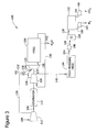
- FIG 3 is a schematic illustration of an exemplary stoichiometric exhaust gas recirculation system (SEGR) 110.
- SEGR 110 includes a first compressor 112 connected to a generator 114 by a first rotatable shaft 116.
- a second compressor 118 is also connected to generator 114 by a second rotatable shaft 120, and to a gas turbine expander 122 by a third rotatable shaft 124.
- a combustor 126 is coupled in flow communication with first compressor 112, and with second compressor 118.
- Combustor 126 receives at least a portion of air compressed by compressors 112 and 118 and via air conduits 128 and 130.
- Combustor 126 is also coupled in flow communication with at least one fuel source 132 and receives fuel from the fuel source, for example, natural gas. The air and fuel are mixed and combusted within combustor 126 which produces hot combustion gases.
- Turbine expander 122 is coupled in flow communication with combustor 126, and turbine expander 122 receives the hot combustion gases via a combustion gas conduit 134. Turbine expander 122 converts the heat energy within the gases to rotational energy.
- SEGR 110 also includes a heat recovery steam generator (HRSG) 136 coupled in flow communication to turbine 122 by an exhaust conduit 138.
- HRSG 136 receives exhaust gases from turbine 122 via exhaust gas conduit 138.
- the exhaust from turbine 112 includes N 2 , H 2 O, and CO 2 .
- HRSG 136 is coupled in flow communication with second compressor 118 via a conduit 140.
- the exhaust gases may be recirculated to second compressor 118 through conduit 140 Water collected in HRSG 136 is removed through outlet conduit 142.
- a portion of the exhaust gases from second compressor 118 is directed to a high pressure HRSG 144 via a conduit 146.
- a separation system 147 is used to separate the excess N 2 from CO 2 from the exhaust gases by compressing the exhaust gases and cooling the compressed gases. Separation system 147 includes HRSG 144, a compressor 148, an intermediate cooler 150, and a separator 152.
- the exhaust gases are directed from HRSG 144 to a compressor 148 via a conduit 154 where the gases are compressed to about 1000 psi to about 2000 psi (about 6,895 kPa to about 13710 kPa).
- the compressed gases are directed to intermediate cooler 150 through a conduit 156 to cool down the gases.
- the cooled gases are directed to separator 152 through a conduit 158 where the CO 2 may be separated using a physical solvent, for example dimethyl-ether-polyethylene-glycol (DEPG) or methyl alcohol, by absorption.
- a non-condensable N 2 rich stream is removed from separator 152 through a conduit 160 to a compressor 162 for sequestration.
- the CO 2 is removed from separator 152 through conduit 164 to a compressor 166 for sequestration.
- intermediate cooler 150 cools the gases to temperatures of between about minus 60°C to about minus 120°C.
- the cooled gases containing CO 2 and N 2 is directed to separator 152 through conduit 158 where the CO 2 is separated as either a liquid or a solid.
- a non-condensable N 2 rich stream is removed from separator 152 through a conduit 160 to a compressor 162 for sequestration.
- the liquid/solid CO 2 is pumped from separator 152 through conduit 164 to a compressor 166 for sequestration.
- approximating language may be applied to modify any quantitative representation that may vary without resulting in a change in the basic function to which it is related. Accordingly, a value modified by a term or terms, such as “about” and “substantially,” may not be limited to the precise value specified, in some cases.
- the modifier "about” used in connection with a quantity is inclusive of the stated value and has the meaning dictated by the context (for example, includes the degree of error associated with the measurement of the particular quantity).
Abstract
Description
- The field of the invention relates generally to turbine engine systems, and more particularly, to turbine engine systems in power generation plants.
- Turbine engines produce mechanical energy using a working fluid supplied to the engines. More specifically, in known turbine engines, the working fluid may be air that is compressed and delivered, along with fuel and oxygen, to a combustor, wherein the fuel-air mixture is ignited. As the fuel-air mixture bums, its energy is released into the working fluid as heat. The temperature rise causes a corresponding increase in the pressure of the working fluid, and following combustion, the working fluid expands as it is discharged from the combustor downstream towards at least one turbine. As the working fluid flows past each turbine, the turbine is rotated and converts the heat energy to mechanical energy in the form of thrust or shaft power connected to a generator.
- Air pollution concerns worldwide have led to stricter emissions standards both domestically and internationally. Pollutant emissions from at least some gas turbines are subject to government standards that regulate the emission of oxides of nitrogen (NOx), unburned hydrocarbons (HC), carbon monoxide (CO), and carbon dioxide (CO2). Air has been used as a working fluid because it is readily available, free, and has predictable compressibility, heat capacity, and reactivity (oxygen content) properties. However, because of the high percentage of nitrogen in air, during the combustion process, nitrogen oxides are formed. In addition, carbon contained in the fuel may combine with oxygen contained in the air to form carbon monoxide and/or carbon dioxide.
- To facilitate reducing NOx emissions, at least some known gas turbine engines operate with reduced combustion temperatures and/or Selective Catalytic Reduction (SCR) equipment. However, operating at reduced combustion temperatures reduces the overall efficiency of the gas turbine engine. Moreover, any benefits gained through using known SCR equipment may be outweighed by the cost of the equipment and/or the cost of disposing the NOx. Similarly, to facilitate reducing CO emissions an oxidation catalyst may be used. To facilitate reducing CO2 emissions, at least some known gas turbine engines channel turbine exhaust through a gas separation unit to separate CO2 from nitrogen (N2), the major component when using air as the working fluid, and at least one CO2 compressor. Again however, the benefits gained through the use of such equipment may be outweighed by the costs of the equipment.
- In one aspect, a method of separating carbon dioxide (CO2) from nitrogen (N2) and oxygen (O2) in a turbine engine system is provided. The turbine engine system includes a first compressor coupled to a turbine expander by a rotatable shaft, and a combustor coupled in flow communication to the compressor and the first turbine. The method includes directing an air stream into an air separation unit (ASU), separating N2 from the air stream in the ASU to form an oxygen (O2) rich air stream, and directing the O2 rich air stream to the combustor to mix with a fuel for combustion forming hot combustion gases, containing O2 and CO2, which are used to rotate the turbine. In some embodiments, the method also includes directing turbine exhaust gases to a heat recovery steam generator (HRSG) to create steam, directing exhaust from the HRSG to a condenser to separate water from a mixture of O2 and CO2 gases, and directing the mixture of O2 and CO2 gases to a separation system, where the CO2 is separated from the O2 gases and removed from the separation system.
- In another aspect, a system in separating CO2 and N2 in a turbine engine apparatus is provided. The system includes an air separation unit (ASU) for separating N2 from an air stream that forms an oxygen (O2) rich air stream, a heat recovery steam generator (HRSG), and a condenser to separate water from a mixture of O2 and CO2 gases from the HRSG. The system also includes a separation system where the CO2 is separated from the O2 gases and removed from the separation system.
- Embodiments of the present invention will now be described, by way of example only, with reference to the accompanying drawings, in which:
-
Figure 1 is a schematic illustration of an exemplary combined cycle power generation plant. -
Figure 2 is a schematic illustration of a CO2 separation system. -
Figure 3 is a schematic illustration of a stoichieometric exhaust gas recirculation system. - Novel methods of producing a carbon dioxide (CO2) rich stream and a nitrogen (N2) rich stream from combustion of a hydrocarbon fuel source (natural gas, oil, coal) are disclosed. Applications of the novel methods involve electricity production, enhanced oil recovery, carbon capture, and sequestration. The methods disclosed provide separation of CO2 and N2 gases which are products of a combustion process. Methods and systems for separating N2 and CO2 from the working air and/or exhaust in turbine engine systems in power generation plants are described below in detail. In addition, oxygen (O2) is separated from a CO2 and O2 mixture in the exhaust of the turbine engine system, and may be recycled back to the oxyfuel combuster of the turbine engine system. Removing the N2 from the working air reduces NOx emissions. Also, the CO2 removed from the exhaust may be sequestered for use in enhanced oil recovery. A stream of removed CO2 may contain no O2 or less that 1 percent of O2. Advantages of the methods and systems described below include removing O2 from a CO2 stream with lower energy and lower costs than known methods. With O2 removed from a CO2 stream, the CO2 stream may be used for injection in an oil well for enhanced oil recovery. Streams of CO2 that do include O2 can be detrimental to oil recovery because of the reactivity of O2. In addition, advantages of the methods and systems may include improved flexibility of operation of a power generation plant, a safer power generation plant because of reduced CO emissions and a reduced need for the use of CO oxidation catalysts.
-
Figure 1 is a schematic illustration of an exemplary combined-cyclepower generation plant 10 that includes a gas turbine engine 12. Gas turbine engine 12 includes acompressor 14 that is coupled to a turbine expander 16 (also referred to in the art as a "turbine") via arotatable shaft 18.Compressor 14 receives air at locally atmospheric pressures and temperatures.Turbine expander 16 is coupled to a firstelectrical generator 20 via a first rotor 22. Gas turbine engine 12 also includes acombustor 24 coupled in flow communication withcompressor 14. Combustor 24 receives at least a portion of recirculated CO2 compressed bycompressor 14 via aconduit 26. In addition, an air separation unit (ASU) 28 is coupled in flow communication withcombustor 24 by aconduit 27. ASU 28 separates N2 from anair stream 30 and makesair stream 30 rich in O2. The O2rich air stream 30 is directed intocombustor 24. The N2 is directed to acompressor 31 through aconduit 29 for compression and sequestration, e.g., by injection underground. - Combustor 24 is also coupled in flow communication with at least one
fuel source 32 and receives fuel from the fuel source, for example, natural gas. The air and fuel are mixed and combusted withincombustor 24 which produces hot combustion gases.Turbine expander 16 is coupled in flow communication withcombustor 24, andturbine expander 16 receives the hot combustion gases via acombustion gas conduit 34. Turbine expander 16 converts the heat energy within the gases to rotational energy. The rotational energy is transmitted togenerator 20 viarotor 36, whereingenerator 20 converts the rotational energy to electrical energy for transmission to at least one load, including, but not limited to, an electrical power grid. - In the exemplary embodiment,
plant 10 also includes asteam turbine engine 40. More specifically,steam turbine engine 40 includes asteam turbine 42 coupled to a secondelectrical generator 44 via asecond rotor 46.Power plant 10 also includes asteam generation system 48. In the exemplary embodiment,system 48 includes a heat recovery steam generator (HRSG) 50 that is coupled in flow communication withturbine 16 via at least oneconduit 52. HRSG 50 receives exhaust gases from turbine expander 16 viaexhaust gas conduit 52. The exhaust from turbine includes O2, H2O, and CO2. HRSG 50 is coupled in flow communication withsteam turbine 42 via asteam conduit 54. - Conduit 54 channels steam from HRSG 50 to
steam turbine 42 which converts the thermal energy in the steam to rotational energy. The rotational energy is transmitted togenerator 44 viarotor 46, whereingenerator 44 converts the rotational energy to electrical energy for transmission to at least one load, including, but not limited to, the electrical power grid. The exhaust steam fromturbine 42 is directed to acondenser 56 where the exhaust steam is condensed to water. Apump 58 is coupled in flow communication withcondenser 56.Pump 58 pumps the condensed water through aconduit 60 that is coupled in flow communication withHRSG 50. - In addition, the exhaust of the
HRSG 50 is directed to acondenser 62 through aconduit 64 that is that is coupled toHRSG 50 andcondenser 62. Exhaust fromHRSG 50 includes O2, H2O, and CO2. Water is removed fromcondenser 62 through anoutlet conduit 66. A portion of CO2 is recirculated back tocompressor 14 through aconduit 68. Aseparation system 69 is used to separate the excess O2 from CO2 by compressing the mixture of CO2 and O2 and cooling the compressed mixture.Separation system 69 includes acompressor 70, aheat exchanger 74, and aseparator 78. - The remainder of the CO2 and O2 is directed to
compressor 70 throughconduit 72 to compress the CO2 and O2 mixture. The compressed CO2 and O2 mixture is directed toheat exchanger 74 through aconduit 76 to cool down the mixture to temperatures of between about minus 60°C to about minus 120°C. The cooled CO2 and O2 mixture is directed toseparator 78 through aconduit 80 where the CO2 is separated as either a liquid or a solid. A non-condensable O2 rich stream is recycled to combustor 24 fromseparator 78 through aconduit 82. The liquid/solid CO2 is pumped fromseparator 78 throughconduit 84 bypump 86 for sequestration. - In another embodiment, a CO2 and O2 separation system 90 replaces
separation system 69 described above. Referring also toFigure 2 ,separation system 90 includes afirst chamber 92 that includes a oxygen transfer material, for example, a metal-metal oxide material, to remove O2 from the CO2 and O2 mixture described above. Any suitable metal-metal oxide may be used, for example, a Cu-CuO material and the like. The oxygen transfer material is oxidized by the O2 thereby removing the O2 from the CO2 and O2 mixture. The CO2 is removed fromfirst chamber 92 through anoutlet conduit 94 for sequestration. The oxidized material is directed to asecond chamber 96 through aconduit 98 where the oxidized material is reduced by reacting with a fuel, for example natural gas. The O2 is removed from the oxidized material by the fuel. The fuel and 02 is removed fromsecond chamber 96 through anoutlet conduit 100 and recirculated to combustor 24 (shown inFigure 1 ). The reduced material is recycled tofirst chamber 92 throughconduit 102. In another embodiment, O2 may be removed from the CO2 and O2 mixture by adding hydrogen (H2) and combusting the mixture using a burner of catalytic oxidizer. The H2 may be generated bypassing a small amount of fuel, for example natural gas, through a reformer. Also, the H2 may be generated by using electricity generated from generator 20 (shown inFigure 1 ) split water. -
Figure 3 is a schematic illustration of an exemplary stoichiometric exhaust gas recirculation system (SEGR) 110.SEGR 110 includes afirst compressor 112 connected to agenerator 114 by a firstrotatable shaft 116. Asecond compressor 118 is also connected togenerator 114 by a second rotatable shaft 120, and to agas turbine expander 122 by a thirdrotatable shaft 124. Acombustor 126 is coupled in flow communication withfirst compressor 112, and withsecond compressor 118.Combustor 126 receives at least a portion of air compressed bycompressors air conduits -
Combustor 126 is also coupled in flow communication with at least onefuel source 132 and receives fuel from the fuel source, for example, natural gas. The air and fuel are mixed and combusted withincombustor 126 which produces hot combustion gases.Turbine expander 122 is coupled in flow communication withcombustor 126, andturbine expander 122 receives the hot combustion gases via acombustion gas conduit 134.Turbine expander 122 converts the heat energy within the gases to rotational energy. -
SEGR 110 also includes a heat recovery steam generator (HRSG) 136 coupled in flow communication toturbine 122 by anexhaust conduit 138.HRSG 136 receives exhaust gases fromturbine 122 viaexhaust gas conduit 138. The exhaust fromturbine 112 includes N2, H2O, and CO2.HRSG 136 is coupled in flow communication withsecond compressor 118 via aconduit 140. The exhaust gases may be recirculated tosecond compressor 118 throughconduit 140 Water collected inHRSG 136 is removed throughoutlet conduit 142. - A portion of the exhaust gases from
second compressor 118 is directed to ahigh pressure HRSG 144 via aconduit 146. A separation system 147 is used to separate the excess N2 from CO2 from the exhaust gases by compressing the exhaust gases and cooling the compressed gases. Separation system 147 includesHRSG 144, acompressor 148, anintermediate cooler 150, and aseparator 152. The exhaust gases are directed fromHRSG 144 to acompressor 148 via aconduit 154 where the gases are compressed to about 1000 psi to about 2000 psi (about 6,895 kPa to about 13710 kPa). - The compressed gases are directed to
intermediate cooler 150 through aconduit 156 to cool down the gases. The cooled gases are directed toseparator 152 through aconduit 158 where the CO2 may be separated using a physical solvent, for example dimethyl-ether-polyethylene-glycol (DEPG) or methyl alcohol, by absorption. A non-condensable N2 rich stream is removed fromseparator 152 through aconduit 160 to acompressor 162 for sequestration. The CO2 is removed fromseparator 152 throughconduit 164 to acompressor 166 for sequestration. - In another embodiment,
intermediate cooler 150 cools the gases to temperatures of between about minus 60°C to about minus 120°C. The cooled gases containing CO2 and N2 is directed toseparator 152 throughconduit 158 where the CO2 is separated as either a liquid or a solid. A non-condensable N2 rich stream is removed fromseparator 152 through aconduit 160 to acompressor 162 for sequestration. The liquid/solid CO2 is pumped fromseparator 152 throughconduit 164 to acompressor 166 for sequestration. - As used herein, approximating language may be applied to modify any quantitative representation that may vary without resulting in a change in the basic function to which it is related. Accordingly, a value modified by a term or terms, such as "about" and "substantially," may not be limited to the precise value specified, in some cases. The modifier "about" used in connection with a quantity is inclusive of the stated value and has the meaning dictated by the context (for example, includes the degree of error associated with the measurement of the particular quantity). "Optional" or "optionally" means that the subsequently described event or circumstance may or may not occur, or that the subsequently identified material may or may not be present, and that the description includes instances where the event or circumstance occurs or where the material is present, and instances where the event or circumstance does not occur or the material is not present. The singular forms "a", "an" and "the" include plural referents unless the context clearly dictates otherwise. All ranges disclosed herein are inclusive of the recited endpoint and independently combinable. As used herein, the phrases "adapted to," "configured to," and the like refer to elements that are sized, arranged or manufactured to form a specified structure or to achieve a specified result.
- Exemplary embodiments of a system for separating O2, CO2 and N2 from a turbine engine are described above in detail. The system is not limited to the specific embodiments described herein, but rather, components of the system may be utilized independently and separately from other components described herein. Although specific features of various embodiments of the invention may be shown in some drawings and not in others, this is for convenience only. In accordance with the principles of the invention, any feature of a drawing may be referenced and/or claimed in combination with any feature of any other drawing.
- This written description uses examples to disclose the invention, including the best mode, and also to enable any person skilled in the art to practice the invention, including making and using any devices or systems and performing any incorporated methods. The patentable scope of the invention is defined by the claims, and may include other examples that occur to those skilled in the art. Such other examples are intended to be within the scope of the claims if they have structural elements that do not differ from the literal language of the claims, or if they include equivalent structural elements with insubstantial differences from the literal language of the claims.
Claims (18)
- A method of separating carbon dioxide (CO2) and nitrogen (N2) in a turbine engine system (12), the turbine engine system comprising a first compressor (14) coupled to a turbine expander (16) by a rotatable shaft (18), and a combustor (24) coupled in flow communication to the compressor and the turbine, said method comprising:directing an air stream (30) into an air separation unit (ASU) (28);separating N2 from the air stream in the ASU to form an oxygen (O2) rich air stream;directing the O2 rich air stream to the combustor to mix with a fuel (32) for combustion forming hot combustion gases containing O2 and CO2, which are used to rotate the turbine;directing turbine expander exhaust gases to a heat recovery steam generator (HRSG) (50) to create steam;directing HRSG exhaust to a condenser (56) to separate water from a mixture of O2 and CO2 gases; anddirecting the mixture of O2 and CO2 gases to a separation system (69) where the CO2 is separated from the O2 gas and removed from the separation system.
- The method in accordance with claim 1, further comprising directing the separated N2 from the ASU (28) to a second compressor (31) to compress the N2.
- The method in accordance with claim 1 or 2, wherein the separation system (69) comprises a compressor (70), a heat exchanger (74) and a separator (78), and said directing the mixture of O2 and CO2 gases to a separation system comprises compressing the mixture of O2 and CO2 gases with the compressor, cooling the mixture of O2 and CO2 gases to a temperature of about minus 60°C to about minus 120°C, and separating non-condensable O2 from liquid or solid CO2.
- The method in accordance with claim 3, wherein the separated CO2 is directed to a compressor (86) to compress the CO2.
- The method in accordance with claim 1 or 2, wherein the separation system (90) comprises a first chamber (92) that has therein an oxygen transfer material and a second chamber (96) coupled to a fuel source, and said directing the mixture of O2 and CO2 gases to a separation system comprises:directing the mixture of O2 and CO2 gases to the first chamber where the O2 is removed from the mixture of O2 and CO2 gases by oxidation of the oxygen transfer material; andremoving the CO2 from the first chamber.
- The method in accordance with claim 5, further comprising directing the oxidized material to the second chamber (96) where the O2 is removed from the oxidized material by reducing the oxidized material with the fuel; and
removing the O2 rich fuel from the second chamber and directing the O2 rich fuel to the combustor (24). - The method in accordance with claim 1 or 2, wherein the separation system comprises (147) a high pressure HRSG (144), a compressor (148), an intermediate cooler (150), and a separator (152), and wherein the air stream is directed into the first compressor (112) and bypassing the ASU, and directing turbine expander (122) exhaust gases to a heat recovery steam generator (HRSG) (136) further comprises:removing water from the HRSG (136);directing cooled gases from the turbine that contain a mixture of N2 and CO2 to a second compressor (118); anddirecting exhaust gases from the second compressor to the high pressure HRSG.
- The method in accordance with claim 7, further comprising:compressing the mixture of N2 and CO2 gases with the separation system compressor (148) to a pressure of about 1000 psi to about 2000 psi;cooling the mixture of N2 and CO2 gases;directing the cooled mixture of N2 and CO2 gases to the separator (152); andseparating the CO2 from the mixture of N2 and CO2 gases with a physical solvent by absorption or as a liquid or a solid.
- The method in accordance with claim 8, further comprising:removing the CO2 from the separator (152); andremoving the N2 from the separator.
- The method in accordance with claim 8 or 9, wherein the physical solvent comprises at least one of dimethyl-ether-polyethylene-glycol (DEPG) and methyl alcohol.
- The method in accordance with claim 8 or 9, further comprising:wherein cooling the mixture of N2 and CO2 gases comprises cooling to a temperature of about minus 60°C to about minus 120°C;and wherein separating the CO2 from the mixture of N2 and CO2 gases comprise separating a liquid or a solid.
- A system for separating CO2 and N2 from combustion products within a turbine engine apparatus (12), said system comprising:an air separation unit (ASU) (28) for separating N2 from an air stream (30) that forms an oxygen (O2) rich air stream;a heat recovery steam generator (HRSG) (50) that produces an exhaust stream;a condenser (56) to separate water from a mixture of O2 and CO2 gases from the HRSG exhaust stream; anda separation system (69) where the CO2 is separated from the O2 gases and removed from the separation system (69).
- The system in accordance with claim 12, wherein the separation system comprises:a compressor (70);a heat exchanger (74) configured to cool a mixture of O2 and CO2 gases to a temperature of about minus 60°C to about minus 120°C; anda separator (78) configured to separate non-condensable O2 from liquid or solid CO2.
- The system in accordance with claim 12, wherein the separation system (69) comprises:a first chamber (92) that has therein an oxygen transfer material, the first chamber (92) is configured to remove O2 from the mixture of O2 and CO2 gases by oxidation of the oxygen transfer material; anda second chamber (96) coupled to a fuel source, the second chamber configured to reduce the oxidized oxygen transfer material by a reaction with the fuel.
- The system in accordance with claim 12, wherein the separation system comprises a high pressure HRSG (144), a compressor (148), an intermediate cooler (150), and a separator (152).
- The system in accordance with claim 15, wherein the system does not include an ASU to separate N2, and wherein:the compressor (148) is configured to compress a mixture of N2 and CO2 gases to a pressure of about 1000 psi to about 2000 psi;the intermediate cooler (150) is configured to cool the mixture of N2 and CO2 gases; andthe separator (152) is configured to include a physical solvent to separate the CO2 from the mixture of N2 and CO2 gases by absorption.
- The system in accordance with claim 16, wherein the physical solvent comprises at least one of dimethyl-ether-polyethylene-glycol (DEPG) and methyl alcohol.
- The system in accordance with claim 15, wherein the system does not include an ASU to separate N2, wherein:the compressor (148) is configured to compress a mixture of N2 and CO2 gases to a pressure of about 1000 psi to about 2000 psi;the intermediate cooler (150) is configured to cool the mixture of N2 and CO2 gases to a temperature of about minus 60°C to about minus 120°C; andthe separator (152) is configured to separate the CO2 from the mixture of N2 and CO2 gases as a liquid or a solid.
Applications Claiming Priority (1)
| Application Number | Priority Date | Filing Date | Title |
|---|---|---|---|
| US13/324,466 US20130145773A1 (en) | 2011-12-13 | 2011-12-13 | Method and system for separating co2 from n2 and o2 in a turbine engine system |
Publications (2)
| Publication Number | Publication Date |
|---|---|
| EP2604823A2 true EP2604823A2 (en) | 2013-06-19 |
| EP2604823A3 EP2604823A3 (en) | 2017-09-20 |
Family
ID=47296993
Family Applications (1)
| Application Number | Title | Priority Date | Filing Date |
|---|---|---|---|
| EP12195675.9A Withdrawn EP2604823A3 (en) | 2011-12-13 | 2012-12-05 | Method and system for separating CO2 from N2 and O2 in a turbine engine system |
Country Status (5)
| Country | Link |
|---|---|
| US (2) | US20130145773A1 (en) |
| EP (1) | EP2604823A3 (en) |
| JP (1) | JP6169840B2 (en) |
| CN (1) | CN103161575A (en) |
| RU (1) | RU2012153420A (en) |
Cited By (1)
| Publication number | Priority date | Publication date | Assignee | Title |
|---|---|---|---|---|
| CN112483350A (en) * | 2020-11-26 | 2021-03-12 | 清华四川能源互联网研究院 | Compressed air energy storage and exhaust comprehensive utilization system and method |
Families Citing this family (16)
| Publication number | Priority date | Publication date | Assignee | Title |
|---|---|---|---|---|
| EA027439B1 (en) * | 2010-07-02 | 2017-07-31 | Эксонмобил Апстрим Рисерч Компани | Integrated power generation systems (embodiments) and method of generating power |
| US9103285B2 (en) * | 2011-01-03 | 2015-08-11 | General Electric Company | Purge system, system including a purge system, and purge method |
| EP2644851A1 (en) * | 2012-03-29 | 2013-10-02 | Alstom Technology Ltd | Method for operating a combined cycle power plant and combined cycle power plant for using such method |
| DE102013200101A1 (en) * | 2013-01-07 | 2014-07-10 | Siemens Aktiengesellschaft | Gas turbine system for generating electrical power by oxyfuel combustion process, has carbon dioxide supply line and fuel supply line to respectively supply carbon dioxide containing fluid medium and gas fuel, over combustion chamber |
| JP6220586B2 (en) * | 2013-07-22 | 2017-10-25 | 8 リバーズ キャピタル,エルエルシー | Gas turbine equipment |
| JP6250332B2 (en) | 2013-08-27 | 2017-12-20 | 8 リバーズ キャピタル,エルエルシー | Gas turbine equipment |
| JP6545436B2 (en) * | 2014-04-03 | 2019-07-17 | 一般財団法人電力中央研究所 | CO2 recovery type closed cycle gasification power generation system |
| US9951689B2 (en) * | 2014-07-17 | 2018-04-24 | Saudi Arabian Oil Company | Integrated calcium looping combined cycle for sour gas applications |
| JP6746689B2 (en) | 2015-09-01 | 2020-08-26 | 8 リバーズ キャピタル,エルエルシー | System and method for power production using a nested CO2 cycle |
| DE102016221394A1 (en) * | 2016-10-31 | 2018-05-03 | Robert Bosch Gmbh | A waste heat recovery system having a working fluid circuit and method of operating such a waste heat recovery system |
| GB2563818A (en) * | 2017-05-05 | 2019-01-02 | Ceox Ltd | Mechanical/electrical power generation system |
| JP7025310B2 (en) * | 2018-09-14 | 2022-02-24 | 一般財団法人電力中央研究所 | Gas turbine combined cycle power generation system, gas turbine combined cycle power generation method |
| CN109812304B (en) * | 2019-03-06 | 2023-08-29 | 上海发电设备成套设计研究院有限责任公司 | Peak regulation power generation system and method integrating carbon dioxide circulation and liquefied air energy storage |
| US11193421B2 (en) * | 2019-06-07 | 2021-12-07 | Saudi Arabian Oil Company | Cold recycle process for gas turbine inlet air cooling |
| JP7351648B2 (en) * | 2019-06-13 | 2023-09-27 | 三菱重工業株式会社 | complex plant |
| GB201917011D0 (en) * | 2019-11-22 | 2020-01-08 | Rolls Royce Plc | Power generation system with carbon capture |
Family Cites Families (14)
| Publication number | Priority date | Publication date | Assignee | Title |
|---|---|---|---|---|
| US4434613A (en) * | 1981-09-02 | 1984-03-06 | General Electric Company | Closed cycle gas turbine for gaseous production |
| US4498289A (en) * | 1982-12-27 | 1985-02-12 | Ian Osgerby | Carbon dioxide power cycle |
| JPH07213860A (en) * | 1994-01-28 | 1995-08-15 | Mitsubishi Heavy Ind Ltd | Co2 recovering method and device therefor |
| JP2710267B2 (en) * | 1994-07-12 | 1998-02-10 | 工業技術院長 | Apparatus for separating carbon dioxide from carbon dioxide-containing gas and combustion apparatus having carbon dioxide separation function |
| JPH0914831A (en) * | 1995-06-27 | 1997-01-17 | Mitsubishi Heavy Ind Ltd | Co2 recovering device and recovering method |
| US5724805A (en) * | 1995-08-21 | 1998-03-10 | University Of Massachusetts-Lowell | Power plant with carbon dioxide capture and zero pollutant emissions |
| JPH11169661A (en) * | 1997-12-12 | 1999-06-29 | Ishikawajima Harima Heavy Ind Co Ltd | Carbon dioxide recovering device |
| KR101263494B1 (en) * | 2002-10-17 | 2013-05-13 | 엔테그리스, 아이엔씨. | Method for Purifying Carbon Dioxide |
| WO2006037320A1 (en) * | 2004-10-08 | 2006-04-13 | Union Engineering A/S | Method for recovery of carbon dioxide from a gas |
| US7266940B2 (en) * | 2005-07-08 | 2007-09-11 | General Electric Company | Systems and methods for power generation with carbon dioxide isolation |
| US7824574B2 (en) * | 2006-09-21 | 2010-11-02 | Eltron Research & Development | Cyclic catalytic upgrading of chemical species using metal oxide materials |
| US7966829B2 (en) * | 2006-12-11 | 2011-06-28 | General Electric Company | Method and system for reducing CO2 emissions in a combustion stream |
| DE102009014447A1 (en) * | 2009-03-23 | 2010-09-30 | Man Turbo Ag | Power plant for IGSC process |
| US20110265445A1 (en) * | 2010-04-30 | 2011-11-03 | General Electric Company | Method for Reducing CO2 Emissions in a Combustion Stream and Industrial Plants Utilizing the Same |
-
2011
- 2011-12-13 US US13/324,466 patent/US20130145773A1/en not_active Abandoned
-
2012
- 2012-12-05 EP EP12195675.9A patent/EP2604823A3/en not_active Withdrawn
- 2012-12-07 JP JP2012267848A patent/JP6169840B2/en not_active Expired - Fee Related
- 2012-12-12 RU RU2012153420/06A patent/RU2012153420A/en not_active Application Discontinuation
- 2012-12-13 CN CN201210541022XA patent/CN103161575A/en active Pending
-
2016
- 2016-01-19 US US15/000,641 patent/US20160131029A1/en not_active Abandoned
Non-Patent Citations (1)
| Title |
|---|
| None |
Cited By (2)
| Publication number | Priority date | Publication date | Assignee | Title |
|---|---|---|---|---|
| CN112483350A (en) * | 2020-11-26 | 2021-03-12 | 清华四川能源互联网研究院 | Compressed air energy storage and exhaust comprehensive utilization system and method |
| CN112483350B (en) * | 2020-11-26 | 2022-03-01 | 清华四川能源互联网研究院 | Compressed air energy storage and exhaust comprehensive utilization system and method |
Also Published As
| Publication number | Publication date |
|---|---|
| JP6169840B2 (en) | 2017-07-26 |
| US20130145773A1 (en) | 2013-06-13 |
| US20160131029A1 (en) | 2016-05-12 |
| EP2604823A3 (en) | 2017-09-20 |
| CN103161575A (en) | 2013-06-19 |
| JP2013124662A (en) | 2013-06-24 |
| RU2012153420A (en) | 2014-06-20 |
Similar Documents
| Publication | Publication Date | Title |
|---|---|---|
| US20160131029A1 (en) | Method and system for separating co2 from n2 and o2 in a turbine engine system | |
| EP2588729B1 (en) | Low emission triple-cycle power generation systems and methods | |
| CA2801494C (en) | Stoichiometric combustion of enriched air with exhaust gas recirculation | |
| JP5128243B2 (en) | Power plants using gas turbines for power generation and methods for reducing CO2 emissions | |
| AU2011305628B2 (en) | System and method for high efficiency power generation using a nitrogen gas working fluid | |
| EP2588732B1 (en) | Low emission triple-cycle power generation systems and methods | |
| US20090193809A1 (en) | Method and system to facilitate combined cycle working fluid modification and combustion thereof | |
| CA2732273C (en) | System and method of operating a power generation system with an alternative working fluid | |
| US20100024378A1 (en) | System and method of operating a gas turbine engine with an alternative working fluid | |
| WO2014124161A1 (en) | System and method for catalyst heat utilization for gas turbine with exhaust gas recirculation | |
| MX2013009834A (en) | Low emission turbine systems incorporating inlet compressor oxidant control apparatus and methods related thereto. | |
| JP2011530033A (en) | System and method for operating a gas turbine engine with an alternative working fluid | |
| US10765994B2 (en) | System and method of recovering carbon dioxide from an exhaust gas stream | |
| US11925894B2 (en) | System and method of recovering carbon dioxide from an exhaust gas stream | |
| US8869502B2 (en) | Fuel reformer system for a turbomachine system |
Legal Events
| Date | Code | Title | Description |
|---|---|---|---|
| PUAI | Public reference made under article 153(3) epc to a published international application that has entered the european phase |
Free format text: ORIGINAL CODE: 0009012 |
|
| AK | Designated contracting states |
Kind code of ref document: A2 Designated state(s): AL AT BE BG CH CY CZ DE DK EE ES FI FR GB GR HR HU IE IS IT LI LT LU LV MC MK MT NL NO PL PT RO RS SE SI SK SM TR |
|
| AX | Request for extension of the european patent |
Extension state: BA ME |
|
| RIC1 | Information provided on ipc code assigned before grant |
Ipc: F02C 3/20 20060101AFI20170418BHEP Ipc: F01K 23/10 20060101ALI20170418BHEP Ipc: F02C 3/34 20060101ALI20170418BHEP |
|
| PUAL | Search report despatched |
Free format text: ORIGINAL CODE: 0009013 |
|
| AK | Designated contracting states |
Kind code of ref document: A3 Designated state(s): AL AT BE BG CH CY CZ DE DK EE ES FI FR GB GR HR HU IE IS IT LI LT LU LV MC MK MT NL NO PL PT RO RS SE SI SK SM TR |
|
| AX | Request for extension of the european patent |
Extension state: BA ME |
|
| RIC1 | Information provided on ipc code assigned before grant |
Ipc: F02C 3/20 20060101AFI20170811BHEP Ipc: F02C 3/34 20060101ALI20170811BHEP Ipc: F01K 23/10 20060101ALI20170811BHEP |
|
| STAA | Information on the status of an ep patent application or granted ep patent |
Free format text: STATUS: THE APPLICATION IS DEEMED TO BE WITHDRAWN |
|
| 18D | Application deemed to be withdrawn |
Effective date: 20180321 |