EP2604387A2 - Pneumatisches Werkzeug mit Rotationsfunktion im Uhrzeigersinn und gegen den Uhrzeigersinn - Google Patents
Pneumatisches Werkzeug mit Rotationsfunktion im Uhrzeigersinn und gegen den Uhrzeigersinn Download PDFInfo
- Publication number
- EP2604387A2 EP2604387A2 EP12196458.9A EP12196458A EP2604387A2 EP 2604387 A2 EP2604387 A2 EP 2604387A2 EP 12196458 A EP12196458 A EP 12196458A EP 2604387 A2 EP2604387 A2 EP 2604387A2
- Authority
- EP
- European Patent Office
- Prior art keywords
- valve
- passage
- housing
- axis
- air
- Prior art date
- Legal status (The legal status is an assumption and is not a legal conclusion. Google has not performed a legal analysis and makes no representation as to the accuracy of the status listed.)
- Withdrawn
Links
Images


Classifications
-
- B—PERFORMING OPERATIONS; TRANSPORTING
- B25—HAND TOOLS; PORTABLE POWER-DRIVEN TOOLS; MANIPULATORS
- B25B—TOOLS OR BENCH DEVICES NOT OTHERWISE PROVIDED FOR, FOR FASTENING, CONNECTING, DISENGAGING OR HOLDING
- B25B21/00—Portable power-driven screw or nut setting or loosening tools; Attachments for drilling apparatus serving the same purpose
-
- F—MECHANICAL ENGINEERING; LIGHTING; HEATING; WEAPONS; BLASTING
- F04—POSITIVE - DISPLACEMENT MACHINES FOR LIQUIDS; PUMPS FOR LIQUIDS OR ELASTIC FLUIDS
- F04B—POSITIVE-DISPLACEMENT MACHINES FOR LIQUIDS; PUMPS
- F04B7/00—Piston machines or pumps characterised by having positively-driven valving
-
- B—PERFORMING OPERATIONS; TRANSPORTING
- B25—HAND TOOLS; PORTABLE POWER-DRIVEN TOOLS; MANIPULATORS
- B25B—TOOLS OR BENCH DEVICES NOT OTHERWISE PROVIDED FOR, FOR FASTENING, CONNECTING, DISENGAGING OR HOLDING
- B25B21/00—Portable power-driven screw or nut setting or loosening tools; Attachments for drilling apparatus serving the same purpose
- B25B21/02—Portable power-driven screw or nut setting or loosening tools; Attachments for drilling apparatus serving the same purpose with means for imparting impact to screwdriver blade or nut socket
- B25B21/026—Impact clutches
Definitions
- This invention relates to a pneumatic tool, and more particularly to a pneumatic tool having clockwise and counterclockwise rotation function.
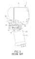
- the air-guiding retainer 13 is disposed in the housing 11, extends along a direction parallel to the X-axis, and is in fluid communication with the first and second passages 122, 123.
- the rotary valve 14 is rotatable about the X-axis in the air-guiding retainer 13, is in fluid communication with the intake passage 112, and has first and second outlets 141, 142.
- the pin 15 extends into the housing 11 along a Y-axis, and is operable to move in the housing 11 to drive rotation of the rotary valve 14.
- the trigger unit 16 is disposed pivotally on the handle 111, and is operable to allow compressed air to flow into the intake passage 112.
- the rotary valve 14 is rotated by the pin 15 between a first position whereat the first outlet 141 is in fluid communication with the first passage 122 so that compressed air flows into the air chamber 120 via the first passage 122 to drive clockwise rotation of the pneumatic tool 1, and a second position whereat the second outlet 142 is in fluid communication with the second passage 123 so that compressed air flows into the air chamber 120 via the second passage 123 to drive counterclockwise rotation of the pneumatic tool 1.
- the air-guiding retainer 13 and the rotary valve 14 are arranged along the direction parallel to the X-axis, they occupy a relatively large space in the housing 11. Furthermore, such an arrangement of the air-guiding retainer 13 and the rotary valve 14 increases largely the width of the handle 111, thereby resulting in difficulties in gripping the handle 111.
- the object of this invention is to provide a pneumatic tool having clockwise and counterclockwise rotation function, which can reduce the space occupied in a housing by a valve unit and which allows smooth flow of compressed air from an intake passage into an air cylinder.
- a pneumatic tool includes a housing, an air cylinder, a valve unit, and a controlling unit.
- the housing has an intake passage adapted to be connected with a compressed air source.
- the air cylinder is disposed in the housing, and includes a cylinder wall centered at an X-axis and defining an air chamber, a valve seat centered at a Z-axis perpendicular to the X-axis and connected to the cylinder wall, a first passage, and a second passage.
- the first and second passages are formed in the cylinder wall, and are in fluid communication with the air chamber and the valve seat.
- the valve unit includes a rotary valve that is disposed in the valve seat and that has an intermediate passage.
- the rotary valve is rotatable about the Z-axis between a first position whereat the intermediate passage is in fluid communication with the first passage in the air cylinder, and a second position whereat the intermediate passage is in fluid communication with the second passage in the air cylinder.
- the controlling unit includes a movable pin disposed movably on the housing and operable to move in the housing along a Y-axis perpendicular to the X-axis and the Z-axis to thereby drive rotation of the rotary valve.
- the rotary valve Since the rotary valve is rotatable about the Z-axis, the space occupied in the housing by the valve unit is reduced significantly, and compressed air can flow smoothly from the intake passage into the air cylinder.
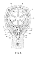
- the preferred embodiment of a pneumatic tool having clockwise and counterclockwise rotation function includes a housing 2, a driving unit 3, an air cylinder 4, a rotor unit 5, a valve unit 6, and a controlling unit 7.
- the air cylinder 4 is disposed in the rear seat 22 of the housing 2, and includes a cylinder wall 41 centered at the X-axis and defining an air chamber 41, a valve seat 42 centered at a Z-axis perpendicular to the X-axis and connected to the cylinder wall 41, first and second passages 43, 44 formed in the cylinder wall 41 and in fluid communication with the air chamber 40 and the valve seat 42, and a projection 45 formed on the cylinder wall 41 and adjacent to the valve seat 42.
- the valve seat 42 has a first opening 421 formed at a side thereof, and a second opening 422 (see Fig. 7 ) formed at an opposite side thereof.
- the controlling unit 7 includes a movable pin 71, a pushing member 72, a positioning member 73, and a resilient member 74.
- the movable pin 71 is movable in the housing body 221 of the housing 2 in a Y-axis perpendicular to the X-axis and the Z-axis, and has a hole 711 formed therethrough.
- the pushing member 72 is disposed between the rotary valve 61 and the movable pin 71 along the X-axis, and has a rack 721 formed at an end thereof and engaging the teeth 611, and an engaging portion 722 formed at an opposite end thereof. The pushing member 72 is obstructed by the projection 45 to maintain engagement between the rack 721 and the teeth 611.
- the positioning member 73 has an engaging portion 731 inserted fittingly into the engaging portion 722 of the pushing member 72, and an intermediate portion extending through the hole 711 of the movable pin 71.
- the resilient member 74 is disposed in a recess 732 of the positioning member 73, and has two ends abutting respectively against the front seat 21 and the positioning member 73 for biasing the engaging portion 731 of the positioning member 73 to move along the direction parallel to the X-axis so as to engage the engaging portion 722 of the pushing member 72, thereby allowing for synchronous movement of the movable in 71, the pushing member 72, and the positioning member 73 along the Y-axis.
- the pneumatic tool of this invention has the following advantages:
Landscapes
- Engineering & Computer Science (AREA)
- Mechanical Engineering (AREA)
- General Engineering & Computer Science (AREA)
- Portable Power Tools In General (AREA)
- Self-Closing Valves And Venting Or Aerating Valves (AREA)
Applications Claiming Priority (1)
| Application Number | Priority Date | Filing Date | Title |
|---|---|---|---|
| TW100146185A TW201323164A (zh) | 2011-12-14 | 2011-12-14 | 具有正、逆轉功能的氣動工具 |
Publications (1)
| Publication Number | Publication Date |
|---|---|
| EP2604387A2 true EP2604387A2 (de) | 2013-06-19 |
Family
ID=47602876
Family Applications (1)
| Application Number | Title | Priority Date | Filing Date |
|---|---|---|---|
| EP12196458.9A Withdrawn EP2604387A2 (de) | 2011-12-14 | 2012-12-11 | Pneumatisches Werkzeug mit Rotationsfunktion im Uhrzeigersinn und gegen den Uhrzeigersinn |
Country Status (3)
| Country | Link |
|---|---|
| US (1) | US20130156622A1 (de) |
| EP (1) | EP2604387A2 (de) |
| TW (1) | TW201323164A (de) |
Cited By (3)
| Publication number | Priority date | Publication date | Assignee | Title |
|---|---|---|---|---|
| EP2894010A3 (de) * | 2014-01-09 | 2015-08-19 | Basso Industry Corp. | Mehrstufige Auslöseranordnung zur Verwendung in einem Druckluftwerkzeug |
| GB2536101A (en) * | 2015-03-06 | 2016-09-07 | Snap On Incorporated | Reversing mechanism for a power tool |
| EP3666472A1 (de) * | 2018-11-21 | 2020-06-17 | Basso Industry Corp. | Pneumatisches werkzeug |
Families Citing this family (3)
| Publication number | Priority date | Publication date | Assignee | Title |
|---|---|---|---|---|
| TWI481484B (zh) * | 2014-03-27 | 2015-04-21 | Basso Ind Corp | An air intake switching device with airtight effect |
| US10328564B2 (en) * | 2015-02-27 | 2019-06-25 | Snap-On Incorporated | Controlling incoming air for a multi-directional rotational motor in a single rotational direction |
| US11541525B2 (en) | 2020-06-22 | 2023-01-03 | Snap-On Incorporated | Reversing mechanism for a power tool |
Citations (1)
| Publication number | Priority date | Publication date | Assignee | Title |
|---|---|---|---|---|
| TWI319346B (en) | 2006-12-27 | 2010-01-11 | Basso Ind Corp | Rotating direction changing structure of a pneumatic tool |
-
2011
- 2011-12-14 TW TW100146185A patent/TW201323164A/zh unknown
-
2012
- 2012-12-11 EP EP12196458.9A patent/EP2604387A2/de not_active Withdrawn
- 2012-12-12 US US13/711,766 patent/US20130156622A1/en not_active Abandoned
Patent Citations (1)
| Publication number | Priority date | Publication date | Assignee | Title |
|---|---|---|---|---|
| TWI319346B (en) | 2006-12-27 | 2010-01-11 | Basso Ind Corp | Rotating direction changing structure of a pneumatic tool |
Cited By (11)
| Publication number | Priority date | Publication date | Assignee | Title |
|---|---|---|---|---|
| EP2894010A3 (de) * | 2014-01-09 | 2015-08-19 | Basso Industry Corp. | Mehrstufige Auslöseranordnung zur Verwendung in einem Druckluftwerkzeug |
| GB2536101A (en) * | 2015-03-06 | 2016-09-07 | Snap On Incorporated | Reversing mechanism for a power tool |
| CN105936032A (zh) * | 2015-03-06 | 2016-09-14 | 施耐宝公司 | 用于动力工具的换向机构 |
| CN105936032B (zh) * | 2015-03-06 | 2018-07-13 | 施耐宝公司 | 用于动力工具的换向机构 |
| AU2017200447B2 (en) * | 2015-03-06 | 2018-11-01 | Snap-On Incorporated | Reversing mechanism for a power tool |
| GB2571860A (en) * | 2015-03-06 | 2019-09-11 | Snap On Tools Corp | Reversing mechanism for a power tool |
| GB2536101B (en) * | 2015-03-06 | 2019-10-30 | Snap On Tools Corp | Reversing mechanism for a power tool |
| GB2571860B (en) * | 2015-03-06 | 2019-12-04 | Snap On Tools Corp | Reversing mechanism for a power tool |
| US10590770B2 (en) | 2015-03-06 | 2020-03-17 | Snap-On Incorporated | Reversing mechanism for a power tool |
| EP3666472A1 (de) * | 2018-11-21 | 2020-06-17 | Basso Industry Corp. | Pneumatisches werkzeug |
| US11364613B2 (en) | 2018-11-21 | 2022-06-21 | Basso Industry Corp. | Pneumatic tool |
Also Published As
| Publication number | Publication date |
|---|---|
| TW201323164A (zh) | 2013-06-16 |
| US20130156622A1 (en) | 2013-06-20 |
Similar Documents
| Publication | Publication Date | Title |
|---|---|---|
| EP2604387A2 (de) | Pneumatisches Werkzeug mit Rotationsfunktion im Uhrzeigersinn und gegen den Uhrzeigersinn | |
| US7802633B2 (en) | Reversible valve assembly for a pneumatic tool | |
| US7594549B2 (en) | Rotating direction switching device for a pneumatic tool | |
| US20070267206A1 (en) | Single-hand operable structure for controlling forward/backward intake of a straight pneumatic wrench | |
| EP2639013B1 (de) | Pneumatisch angetriebener Ratschenschlüssel | |
| TWI477362B (zh) | A single tool is used to switch the pneumatic tool that reverses and adjusts the speed | |
| US20140020923A1 (en) | Pneumatic tool | |
| US9322417B2 (en) | Motor assembly for pneumatic tool | |
| US20030010513A1 (en) | Single push button reverse valve system for a pneumatic tool | |
| TW201632319A (zh) | 用於動力工具的換向機構 | |
| TWM518145U (zh) | 單手換向及調速的氣動工具 | |
| US20030010514A1 (en) | Single push button reverse valve system for a pneumatic tool | |
| EP3725463B1 (de) | Pneumatisches werkzeug | |
| US20120325510A1 (en) | Impact wrench with improved redirection switch | |
| CN102581377B (zh) | 往复切割工具 | |
| CN102581378B (zh) | 切割工具 | |
| JP5153273B2 (ja) | 空気動力工具用の切換バルブ・アセンブリ | |
| JP2008073841A5 (de) | ||
| US20160236338A1 (en) | Reversing control mechanism of pneumatic tools | |
| CN102581379B (zh) | 往复切割工具 | |
| US9630309B2 (en) | Handle body for pneumatic tool | |
| US20140083257A1 (en) | Power driven ratchet wrench having an eccentric yoke | |
| TW201720589A (zh) | 單手換向及調速的氣動工具 | |
| EP3666472B1 (de) | Pneumatisches werkzeug | |
| TWI538786B (zh) | 正反轉切換機構 |
Legal Events
| Date | Code | Title | Description |
|---|---|---|---|
| PUAI | Public reference made under article 153(3) epc to a published international application that has entered the european phase |
Free format text: ORIGINAL CODE: 0009012 |
|
| AK | Designated contracting states |
Kind code of ref document: A2 Designated state(s): AL AT BE BG CH CY CZ DE DK EE ES FI FR GB GR HR HU IE IS IT LI LT LU LV MC MK MT NL NO PL PT RO RS SE SI SK SM TR |
|
| AX | Request for extension of the european patent |
Extension state: BA ME |
|
| STAA | Information on the status of an ep patent application or granted ep patent |
Free format text: STATUS: REQUEST FOR EXAMINATION WAS MADE |
|
| 17P | Request for examination filed |
Effective date: 20130604 |
|
| RBV | Designated contracting states (corrected) |
Designated state(s): AL AT BE BG CH CY CZ DE DK EE ES FI FR GB GR HR HU IE IS IT LI LT LU LV MC MK MT NL NO PL PT RO RS SE SI SK SM TR |
|
| R17P | Request for examination filed (corrected) |
Effective date: 20130531 |
|
| RBV | Designated contracting states (corrected) |
Designated state(s): AL AT BE BG CH CY CZ DE DK EE ES FI FR GB GR HR HU IE IS IT LI LT LU LV MC MK MT NL NO PL PT RO RS SE SI SK SM TR |
|
| STAA | Information on the status of an ep patent application or granted ep patent |
Free format text: STATUS: THE APPLICATION HAS BEEN WITHDRAWN |
|
| 18W | Application withdrawn |
Effective date: 20151030 |