EP2603738B1 - Mischvorrichtung zur mischung von verbrennungsluft und gas sowie feuerungseinrichtung - Google Patents
Mischvorrichtung zur mischung von verbrennungsluft und gas sowie feuerungseinrichtung Download PDFInfo
- Publication number
- EP2603738B1 EP2603738B1 EP11730250.5A EP11730250A EP2603738B1 EP 2603738 B1 EP2603738 B1 EP 2603738B1 EP 11730250 A EP11730250 A EP 11730250A EP 2603738 B1 EP2603738 B1 EP 2603738B1
- Authority
- EP
- European Patent Office
- Prior art keywords
- gas
- nozzle
- mixing device
- gasket
- gas inlet
- Prior art date
- Legal status (The legal status is an assumption and is not a legal conclusion. Google has not performed a legal analysis and makes no representation as to the accuracy of the status listed.)
- Active
Links
- 238000002485 combustion reaction Methods 0.000 title claims description 11
- 238000010304 firing Methods 0.000 title claims description 4
- 238000007789 sealing Methods 0.000 claims description 7
- 230000004323 axial length Effects 0.000 claims description 6
- 230000001105 regulatory effect Effects 0.000 claims description 6
- 239000000203 mixture Substances 0.000 claims description 2
- 239000007789 gas Substances 0.000 description 160
- 230000007704 transition Effects 0.000 description 7
- 238000012549 training Methods 0.000 description 5
- 239000003570 air Substances 0.000 description 4
- 238000013461 design Methods 0.000 description 4
- 230000002349 favourable effect Effects 0.000 description 4
- VNWKTOKETHGBQD-UHFFFAOYSA-N methane Chemical compound C VNWKTOKETHGBQD-UHFFFAOYSA-N 0.000 description 4
- 239000000853 adhesive Substances 0.000 description 3
- 230000001070 adhesive effect Effects 0.000 description 3
- 238000009434 installation Methods 0.000 description 3
- 239000000463 material Substances 0.000 description 3
- 239000003345 natural gas Substances 0.000 description 3
- 239000011324 bead Substances 0.000 description 2
- 238000010276 construction Methods 0.000 description 2
- 238000011161 development Methods 0.000 description 2
- 230000018109 developmental process Effects 0.000 description 2
- 229920002943 EPDM rubber Polymers 0.000 description 1
- 229920000459 Nitrile rubber Polymers 0.000 description 1
- 239000012080 ambient air Substances 0.000 description 1
- 230000015572 biosynthetic process Effects 0.000 description 1
- 238000006243 chemical reaction Methods 0.000 description 1
- 238000004891 communication Methods 0.000 description 1
- 230000006835 compression Effects 0.000 description 1
- 238000007906 compression Methods 0.000 description 1
- 239000012530 fluid Substances 0.000 description 1
- 238000005755 formation reaction Methods 0.000 description 1
- 238000010438 heat treatment Methods 0.000 description 1
- 239000007788 liquid Substances 0.000 description 1
- 238000004519 manufacturing process Methods 0.000 description 1
- 238000000034 method Methods 0.000 description 1
- 230000002093 peripheral effect Effects 0.000 description 1
- 229920001296 polysiloxane Polymers 0.000 description 1
- 239000003566 sealing material Substances 0.000 description 1
Images


Classifications
-
- F—MECHANICAL ENGINEERING; LIGHTING; HEATING; WEAPONS; BLASTING
- F23—COMBUSTION APPARATUS; COMBUSTION PROCESSES
- F23D—BURNERS
- F23D14/00—Burners for combustion of a gas, e.g. of a gas stored under pressure as a liquid
- F23D14/02—Premix gas burners, i.e. in which gaseous fuel is mixed with combustion air upstream of the combustion zone
- F23D14/04—Premix gas burners, i.e. in which gaseous fuel is mixed with combustion air upstream of the combustion zone induction type, e.g. Bunsen burner
-
- F—MECHANICAL ENGINEERING; LIGHTING; HEATING; WEAPONS; BLASTING
- F23—COMBUSTION APPARATUS; COMBUSTION PROCESSES
- F23K—FEEDING FUEL TO COMBUSTION APPARATUS
- F23K5/00—Feeding or distributing other fuel to combustion apparatus
- F23K5/002—Gaseous fuel
- F23K5/007—Details
-
- F—MECHANICAL ENGINEERING; LIGHTING; HEATING; WEAPONS; BLASTING
- F23—COMBUSTION APPARATUS; COMBUSTION PROCESSES
- F23K—FEEDING FUEL TO COMBUSTION APPARATUS
- F23K2400/00—Pretreatment and supply of gaseous fuel
- F23K2400/20—Supply line arrangements
Definitions
- the invention relates to a mixing device for premixing combustion air and gas with a device for gas supply having a gas outlet and a nozzle, wherein on the nozzle or a nozzle disposed on the bypass element, a gas inlet is provided and the gas path from the gas outlet to the gas inlet through a is sealed from the gas outlet to the gas inlet extending seal. Furthermore, the invention relates to a firing device with a gas burner with a combustion chamber, a blower and a mixing device, wherein the mixture of combustion air and gas provided by the mixing device is supplied to the combustion chamber of the gas burner by means of the blower.
- a mixing device having the features of claim 1.
- a device for Gas supply can be used here a gas control device.
- the gas control may also be located at the nozzle or in front of the gas valve and the gas supply device may be a (safety) gas valve.
- any training is understood, to which a seal can be brought into abutment, wherein a gas inlet nozzle can be formed in a corresponding training in the interior of the nozzle or the bridging element as a wall.
- gas regulator is defined as any device capable of providing the gas provided by the gas line in desired amounts.
- die is meant any component that fluidly mixes combustion air with gas within a housing, i. general mixing devices even without “nozzle function” are also included.
- the term “gas path” is understood to mean the flow path of the gas.
- the “gas outlet” is determined by a range at which the gas leaves the gas regulator or the gas valve. Although in the following only training with gas control device are described, it is understood that for this purpose in all versions, the gas valve can be used. The gas flow control then takes place, for example, at the nozzle.
- the gas inlet nozzle may be arranged indirectly via a bridging element on the nozzle in a preferred embodiment. It is therefore not necessary to form the gas inlet nozzle directly to the nozzle, but the bridging element can take any shape and bridge any distances between the gas regulator and the nozzle. In a preferred embodiment, the gas inlet nozzle protrudes outward beyond an edge plane of the nozzle or of the bridging element, so that the seal can be brought into contact with the nozzle on the outside or on the inside.
- any design of the nozzle in which a portion of the respective nozzle over an edge plane of the component, on which the nozzle is arranged, protrudes.
- a gas path is provided from the gas control valve to the nozzle, wherein the gas inlet can be arranged on the bridging element so that it is substantially aligned with the gas outlet of the gas control valve and axially protrudes from a peripheral plane of the bridging element.
- the invention includes the possible alternatives to provide the gas control device either an additional gas outlet, the outside is at least partially enclosed by the seal, or form the gas outlet on the gas control device as an outlet and the gasket seal inside to secure the gas outlet.
- the gas outlet nozzle is saved and the manufacturing costs as well as the assembly time are reduced.
- the seal can be arranged either outside or inside.
- the gas outlet nozzle and the gas inlet nozzle each may be substantially tubular and formed with substantially identical diameters, so that the seal can surround the respective nozzle surface fitting.
- the fixed in diameter seal acts at such a favorable training with substantially identical forces on the outer surfaces of the nozzle.
- "essentially tubular" also includes oval formations.
- a nozzle may be formed oval-shaped and with a larger passage area than the opposite tubular nozzle.
- the gas outlet and gas inlet ports are arranged in a manner that their respective axially facing axial outer edges are spaced apart, the distance being preferably between 0.5 and 3 mm, more preferably between 1 and 2 mm, even more preferably 1 mm.
- the direction in which the gas outlet nozzle and the gas inlet nozzle face one another is generally defined as "axial"; in a rohrfömigen training of the nozzle would be “axial” thus the axial longitudinal direction of the tube.
- large distances of several centimeters can be ensured if, for example, the bridging element is formed by the seal itself.
- the spacing of the outer edges allows a flexible arrangement of the components, which will indeed be formed substantially flush with respect to the nozzle, but need not necessarily be exactly defined.
- a certain offset of the nozzle can be compensated by the elasticity of the seal.
- the spacing of the connecting pieces is selected to be small so that the gas flow from the gas outlet or gas outlet nozzle into the inlet nozzle remains substantially unaffected.
- the nozzle can be arranged butting, whereby the best aerodynamic result is achieved, however, however, given a radial freedom of movement.
- the seal may be formed as a preformed seal, which compensates for the corresponding offset of several centimeters. Smaller tolerances are additionally possible by the elasticity of the sealing material, preferably silicone, NBR or EPDM. In addition to elasticity, these materials have the compelling advantage of being gas-resistant.
- a simple adhesive bond between the outer surfaces the neck and the inside of the seal or the inner surface of the gas outlet and the gas inlet nozzle and the outer surfaces of the seal may be provided.
- the sockets have in their outwardly projecting portions on outside lamellae or external thread, can engage in the corresponding recesses of the seal on the inside or an internal thread.
- the lamellae or the thread can be provided correspondingly on the inside on the gas outlet or the gas inlet stub.
- Such attachment is advantageous because it prevents slipping of the seal on the one hand, but at the same time a high gas tightness is ensured with a releasably secured seal.
- a mounting with fins on the nozzle and corresponding recesses on the seals the gas-tightness is guaranteed even at several points of contact between nozzle and seal.
- Each projecting portion of the nozzle may be between 4 and 50 mm long, in a preferred embodiment between 25 and 30 mm long, in order to ensure a sufficient contact surface, so that the gas-tightness between seal and nozzle is ensured.
- the axial length of the seal can be greater than the length between gas regulator and nozzle or bridging element to be bridged length, so that the seal forms a bead in its axial central region.
- This additional material of the seal in the axial direction ensures the possibility of compensation of relative movements of the gas control device relative to the nozzle or the bridging element, so that a seal is ensured, even if the nozzles are not arranged exactly in alignment.
- the axial length of the seal may further be formed such that at least one, but preferably both of the axial end portions of the seal on the respective subsequent assembly (gas regulator, nozzle, bridging element) is applied. In this way, on the one hand additional sealing surfaces are created in the radial direction, on the other hand experiences the seal always a compression in the axial direction, so that unintentional release is excluded.
- the gas outlet can be releasably attached to the gas regulator and the gas inlet nozzle releasably secured to the nozzle or the bridging element, alternatively, however, the nozzles can also be an integral part of these units.
- the detachable arrangement can be realized for example by a screw. It is advantageous in terms of mounting capability, since the individual components can be prepared and assembled independently. An integral construction, for example, in that the respective nozzle is injection-molded directly onto the component with, shortens the assembly, since additional attachment steps of the nozzle on the respective unit omitted.
- a diaphragm is additionally arranged in the gas path from the gas control device to the nozzle or the bridging element, which limits the amount of gas flow.
- liquid gas can also be provided by gas control devices.
- the heating is often installed very early in the construction process, so that first liquefied gas and later natural gas can be fired.
- Liquefied gas is so highly caloric that the amount supplied via the gas regulator must be limited.
- One solution would be to adjust the gas control unit according consuming, but what special knowledge of the installer are necessary. According to the invention, therefore, a diaphragm arranged in the gas path is proposed which has a reduced cross-section and thus limits the gas flow in a predefined manner.
- the aperture When switching to natural gas, the aperture can be easily removed.
- the panel on the outside may be surrounded by the seal, so that a seal of the gas path in this area can be provided with a single seal and its sealing surfaces to the gas outlet and the gas inlet nozzle.
- the aperture can be inserted into the seal, knotted or injected beforehand.
- the bezel is formed as a disk with an internal hole that can be placed in any direction within the gasket. The bezel can be included in the initial installation of the gas control unit to be able to easily, inexpensively and quickly mounted to realize a conversion to LPG. Special knowledge of the installer is not necessary.
- the seal may be formed with a projection which, when installed, can press against a flange section of the panel and thus fix it in the gas inlet connection.
- the gas inlet into the nozzle is thus defined limited.
- the bezel is fixed in the components and can be pre-inserted into the gas inlet nozzle or gasket for easier installation. Handling for the installer is thus once again simplified.
- Claim 14 further determines the firing device comprising a mixing device according to the invention.
- the dimensions given here are, for example, by measuring means Caliper verifiable.
- Fig. 1 is a detailed view of a mixing device in which a gas control device 1 and a nozzle 3, in particular a Venturi nozzle, are provided.
- a gas control device On the way to the burner in the nozzle 3, the supplied from the gas control device or the gas valve 1 (hereinafter referred to only as a gas control device) provided in a predetermined amount of gas with ambient air.
- the gas control device 1 has at the gas outlet 2 on a built-in gas control device 1 tubular gas outlet 7, which protrudes in the axial direction to the nozzle 3 outwards.
- a gas inlet 2 'in the form of a gas inlet nozzle 5 is provided which extends over an edge plane the nozzle 3 protrudes in the axial direction to the outside.
- the gas inlet nozzle 5 is screwed into the nozzle 3 and thus releasably secured thereto.
- the gas inlet 5 can be integrally integrated in the nozzle 3.
- a seal 6 is provided which sealingly surrounds the gas outlet port 7 and the gas inlet port 5 on the outside over a predetermined axial length and seals the gas path from the gas outlet 2 of the gas control device 1 to the nozzle 3.
- the nozzle 5, 7 may have a smooth surface, so that the seal 6 is easily pushed. An additional attachment of the seal 6 is not necessary, since the fixed positioning of the gas control device 1 and the nozzle 3 causes acting on the seal 6 no external forces.
- the sockets 5, 7 are axially spaced to ensure the greatest possible tolerance compensation of the components to each other.
- the axial length of the seal 6 is greater than the distance between the gas control device 1 and the nozzle 3, so that the seal forms a bead 11.
- This additional material ensures on the one hand a simple installation, on the other hand, the axial end portions of the seal 6 are brought to the gas control device 1 and the nozzle 3 with an edge-contact surface 10 for concern. In this way, in addition to a secure attachment creates an additional seal on the radially extending surfaces.
- the seal 6 may additionally be attached to the nozzle 5, 7 by means of adhesive.
- Fig. 2 an alternative arrangement is shown in which the gas inlet nozzle 5 is arranged on a bridging element 4, which is in direct connection to the nozzle 3.
- the sockets 5, 7 are shown with a small distance in the axial direction, but may also be in abutment with each other.
- the seal 6 is in each case pushed on the outside over the outwardly projecting portions of the connecting pieces 5, 7.
- the seal 6 rests with its axial end portion on the bridging element 4, so that axial edge contact surfaces 10 are ensured.
- the seal 6 has at its axial end portion in the region of the gas inlet nozzle 5 a plurality of, in the example shown, three mutually axially spaced bearing surfaces 9, formed by the fact that run inside the seal two full recesses.
- the gas outlet 7 has, in the outwardly projecting portion fins 8, engage in the corresponding recesses on the inside of the seal 6.
- the seal 6 is pushed over the fins 8, so that a latching connection with sealing bearing surfaces 9 between the fins 8 and the recesses of the seal 6 is ensured.
- the gas outlet port 7 and the gas inlet port 5 are each formed tubular with identical diameters, so that the gas path from the gas control device 1 to the bridging element 4 and the nozzle 3 is favorable in terms of flow.
- a further alternative embodiment is shown, wherein the seal 6 is sealingly attached on the inside to the gas outlet 2 of the gas control device 1.
- the seal 6 is screwed into the gas outlet of the gas control device until it abuts with its axial end to the gas regulator and forms a radial sealing surface 10 in addition to the seal over the thread.
- the gas inlet nozzle 5 at the gas inlet 2 ' which can be arranged arbitrarily on a bridging element 4 or a nozzle 3, has a radial distance (offset) v to the gas outlet 2.
- the distance v may be several cm, so that the seal 6 is formed as a preformed seal, which bridges the distance v via a sloping section and is just connected to the gas inlet 5. If the orientation of the seal 6 to the nozzle 3 is not correct, the seal 6 can be rotated over the thread until it fits axially into the gas inlet 5 of the nozzle 3. The axial end portion of the seal 6 is sealingly attached to the inside of the gas inlet nozzle 5, optionally selected one of the above-described fins, threads or adhesive joints can be.
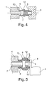
- Fig. 4 an embodiment of the invention is shown, wherein in the gas path of the gas control device 1 to the nozzle 3, a diaphragm 12 is arranged, which has a relation to the nozzle 5, 7 reduced cross-section.
- the panel is surrounded on the outside by the seal 6.
- the aperture 12 is inserted into the gas inlet nozzle 5, but it may also be made shorter and be held exclusively by the seal 6.
- the flange portion of the aperture 12 is buttoned into a recess of the seal 6.
- Fig. 5 discloses an alternative embodiment of the arrangement of a diaphragm 12, wherein the seal 6 is formed with a projection 13 which presses against the flange portion of the aperture 12 and thus fixed to the gas inlet port 5 of the bridging element 4 (or nozzle 3).
- the aperture 12 is inserted with its part opposite the flange portion in the gas inlet 5.
- Fig. 6 shows an alternative embodiment of the solution according to Fig. 2 , wherein the seal 6 on the gas control device 1 according to Fig. 1 is arranged.
- the bridging element 4 is bridged from the gas outlet 2 of the gas regulating device to the gas inlet 2 'of the bridging element 4, the nozzle 3 (not shown, but as shown in FIG Fig. 5 ) is directly in fluid communication with the bridging element 4.
- the seal 6 encloses the bridging element 4 on both sides, wherein the respective ends of the seal 6 surround the outer edges of the bridging element 4.
- the seal is asymmetrical and thus ensures an arrangement over the entire outer edge of the bridging element 4.
- the gas control device 1 and the nozzle 3 are arranged on a holding device, not shown, such that the seal 6 is free from external forces and stresses after assembly.
- the invention is not limited in its execution to the above-mentioned preferred embodiments. Rather, a number of variants is conceivable, which makes use of the illustrated solution even with fundamentally different types of use.
- the gasket may be skewed onto a stub in addition to a louvered latch.
- a design of the gas inlet nozzle 5 through the inner wall of the nozzle 3 and the bridging element 4 is also included for all versions.
Landscapes
- Engineering & Computer Science (AREA)
- Chemical & Material Sciences (AREA)
- Combustion & Propulsion (AREA)
- Mechanical Engineering (AREA)
- General Engineering & Computer Science (AREA)
- Feeding And Controlling Fuel (AREA)
Description
- Die Erfindung betrifft eine Mischvorrichtung zur Vormischung von Verbrennungsluft und Gas mit einem einen Gasauslass aufweisenden Vorrichtung zur Gaszuführung und einer Düse, wobei an der Düse oder einem an der Düse angeordneten Überbrückungselement ein Gaseinlass vorgesehen ist und der Gasweg von dem Gasauslass zu dem Gaseinlass durch eine sich von dem Gasauslass zu dem Gaseinlass erstreckende Dichtung abgedichtet ist. Ferner betrifft die Erfindung eine Feuerungseinrichtung mit einem Gasbrenner mit Brennkammer, einem Gebläse und einer Mischvorrichtung, wobei das durch die Mischvorrichtung bereitgestellte Gemisch aus Verbrennungsluft und Gas der Brennkammer des Gasbrenners mittels dem Gebläse zugeführt wird.
- Aus dem Stand der Technik sind Mischvorrichtungen zum Mischen von Gas und Verbrennungsluft bekannt. Beispielsweise offenbart die
DE 10 2005 007 123 B3 eine aus Gasregelgerät und Venturidüse gebildete Mischeinheit, bei der ein Gasauslassstutzen des Gasregelgeräts in eine entsprechende Ausnehmung des Gehäuses der Venturidüse eingesteckt wird, um eine gasdichte Verbindung der beiden Bauteile zu gewährleisten. Das Gasregelgerät und die Venturidüse sind starr miteinander verbunden. Die möglichen Toleranzen der einzelnen Bauteile sind somit sehr gering. Um bei der Anordnung der verschiedenen Bauteile eine größere Gestaltungsfreiheit zu gewährleisten, wäre es jedoch wünschenswert, eine flexiblere Verbindungsmöglichkeit realisieren zu könnenUS 2007/0218776 A1 offenbart eine Mischvorrichtung gemäß dem Oberbegriff von Anspruch 1. - Es ist demzufolge die Aufgabe der vorliegenden Erfindung, eine montagefreundliche Mischvorrichtung bereitzustellen, bei der das Gasregelgerät und die Düse zwar gasdicht, jedoch mit möglichem Toleranzausgleich und somit nicht notwendigerweise unmittelbar und starr miteinander verbunden sind.
- Die vorliegende Aufgabe wird durch eine Mischvorrichtung mit den Merkmalen des Anspruchs 1 gelöst. Als Vorrichtung zur Gaszuführung kann hierbei ein Gasregelgerät verwendet werden. Alternativ kann die Gasregelung auch an der Düse oder vor dem Gasventil angeordnet und die Vorrichtung zur Gaszuführung ein (Sicherheits)-Gasventil sein.
- Als Gaseinlass wird jede Ausbildung verstanden, an die eine Dichtung zur Anlage gebracht werden kann, wobei ein Gaseinlassstutzen in einer entsprechenden Ausbildung auch im Inneren der Düse oder des Überbrückungselements als Wandung ausgebildet sein kann. Das Merkmal "Gasregelgerät" ist definiert als jede Vorrichtung, die geeignet ist, das durch die Gasleitung bereitgestellte Gas in gewünschten Mengen zur Verfügung zu stellen. Als "Düse" ist jedes Bauteil zu verstehen, das strömungstechnisch Verbrennungsluft mit Gas innerhalb eines Gehäuses mischt, d.h. allgemeine Mischeinrichtungen auch ohne "Düsenfunktion" sind ebenfalls umfasst. Als "Gasweg" wird der Strömungsweg des Gases verstanden. Der "Gasauslass" wird durch einen Bereich bestimmt, bei dem das Gas das Gasregelgerät bzw. das Gasventil verlässt. Auch wenn im Folgenden lediglich Ausbildungen mit Gasregelgerät beschrieben sind, versteht sich, dass hierfür in allen Ausführungen auch das Gasventil zum Einsatz gebracht werden kann. Die Gasmengenregelung erfolgt dann beispielsweise an der Düse.
- Zur Erhöhung der Flexibilität der Anordnung der verschiedenen Bauteile und zur Gewährleistung eines höheren Toleranzausgleichs kann in einer bevorzugten Weiterbildung der Gaseinlassstutzen mittelbar über ein Überbrückungselement an der Düse angeordnet sein. Es ist demzufolge nicht notwendig, den Gaseinlassstutzen unmittelbar an der Düse auszubilden, vielmehr kann das Überbrückungselement beliebige Gestalten annehmen und etwaige Abstände zwischen dem Gasregelgerät und der Düse überbrücken. In einer bevorzugten Ausführung steht der Gaseinlassstutzen über eine Randebene der Düse bzw. des Überbrückungselements nach außen hervor, so dass die Dichtung an den Stutzen außen- oder innenseitig zur Anlage gebracht werden kann. Als "nach außen hin hervorstehend" wird vorliegend jede Ausbildung der Stutzen verstanden, bei der ein Abschnitt des jeweiligen Stutzens über eine Randebene des Bauteils, an dem der Stutzen angeordnet ist, hervorsteht. Bei der Verwendung eines Überbrückungselements wird ein Gasweg von dem Gasregelventil zur Düse bereitgestellt, wobei der Gaseinlassstutzen derart am Überbrückungselement angeordnet sein kann, dass er im Wesentlichen fluchtend zu dem Gasauslassstutzen des Gasregelventils verläuft und aus einer Randebene des Überbrückungselements axial hervorsteht. Durch die Verwendung eines Überbrückungselements können das Gasregelgerät und die Düse in verschiedenen Höhenebenen und somit unabhängig voneinander angeordnet sein, wodurch die Gestaltungsfreiheit bei der Anordnung der verschiedenen Bauteile flexibler und der Toleranzausgleich größer werden.
- Die Erfindung umfasst die möglichen Alternativen, am Gasregelgerät wahlweise einen zusätzlichen Gasauslassstutzen vorzusehen, der außenseitig zumindest abschnittsweise von der Dichtung umschlossen ist, oder den Gasauslass an dem Gasregelgerät als Auslassöffnung auszubilden und die Dichtung innenseitig an dem Gasauslass dichtend zu befestigen. Bei einer Ausbildung mit innenseitig an dem Gasauslass befestigter Dichtung wir der Gasauslassstutzen eingespart und die Herstellungskoten sowie die Montagezeit verringert. Am Gaseinlass bzw. Gaseinlassstutzen kann die Dichtung wahlweise außenseitig oder innenseitig angeordnet werden.
- In einer Ausführungsform mit zwei Stutzen können der Gasauslassstutzen und der Gaseinlassstutzen jeweils im Wesentlichen rohrförmig und mit im Wesentlichen identischen Durchmessern ausgebildet sein, so dass die Dichtung die jeweiligen Stutzen flächig anliegend umschließen kann. Die in ihrem Durchmesser festgelegte Dichtung wirkt bei einer derartig günstigen Ausbildung mit im Wesentlichen identischen Kräften auf die Außenflächen der Stutzen. "Im Wesentlichen rohrförmig" schließt jedoch auch ovale Ausbildungen mit ein. Ferner kann ein Stutzen ovalförmig und mit größerer Durchtrittsfläche ausgebildet sein als der gegenüberliegende rohrförmige Stutzen.
- Vorzugsweise sind der Gasauslass- und der Gaseinlassstutzen in einer Weise angeordnet, dass ihre jeweiligen, zueinander weisenden axialen Außenkanten beabstandet sind, wobei der Abstand vorzugsweise zwischen 0,5 und 3 mm, weiter bevorzugt zwischen 1 und 2 mm, noch bevorzugter 1 mm beträgt. Als "axial" ist vorliegend generell diejenige Richtung bestimmt, in die der Gasauslassstutzen und der Gaseinlassstutzen zueinander weisen; bei einer rohrfömigen Ausbildung der Stutzen wäre "axial" somit die axiale Längsrichtung des Rohres. Alternativ können auch große Abstände von mehreren Zentimetern gewährleistet sein, wenn beispielsweise das Überbrückungselement von der Dichtung selbst gebildet ist. Die Beabstandung der Außenkanten ermöglicht eine flexible Anordnung der Bauteile, die zwar bezüglich der Stutzen im Wesentlichen fluchtend ausgebildet sein wird, jedoch nicht notwendigerweise exakt festgelegt sein muss. Ein gewisser Versatz der Stutzen kann durch die Elastizität der Dichtung ausgeglichen werden. Der Abstand der Stutzen wird jedoch soweit möglich gering gewählt, so dass die Gasströmung von dem Gasauslass bzw. Gasauslassstutzen in den Einlassstutzen im Wesentlichen unbeeinflusst bleibt. In einer günstigen Ausführung können die Stutzen stoßend angeordnet sein, wodurch das strömungstechnisch beste Ergebnis erzielt wird, gleichwohl jedoch eine radiale Bewegungsfreiheit gegeben ist.
- In einer alternativen Ausbildung kann bewusst ein Versatz zwischen Gasauslass bzw. Gasauslassstutzen und Gaseinlassstutzen vorgesehen sein, der über die Dichtung ausgleichbar ist. Hierzu kann die Dichtung als vorgeformte Dichtung ausgebildet sein, die den entsprechenden Versatz von mehreren Zentimetern ausgleicht. Kleinere Toleranzen sind zusätzlich durch die Elastizität des Dichtungswerkstoffs, vorzugsweise Silikon, NBR oder EPDM möglich. Diese Materialien bieten neben der Elastizität den zwingenden Vorteil, gasbeständig zu sein.
- Zur Befestigung der Dichtung an den Stutzen bzw. dem Gaseinlassstutzen und dem Gasauslass kann eine einfache Klebeverbindung zwischen den Außenflächen der Stutzen und der Innenseite der Dichtung bzw. der Innenfläche des Gasauslasses und des Gaseinlassstutzens und den Außenflächen der Dichtung vorgesehen sein. In einer bevorzugten Ausführung weisen die Stutzen in ihren nach außen hin hervorstehenden Abschnitten außenseitige Lamellen bzw. Außengewinde auf, in die entsprechenden Ausnehmungen der Dichtung auf deren Innenseite bzw. ein Innengewinde eingreifen können. Bei einer innenseitigen Anordnung der Dichtung können die Lamellen bzw. das Gewinde entsprechend innenseitig an dem Gasauslass bzw. dem Gaseinlassstutzen vorgesehen sein. Eine derartige Befestigung ist deshalb vorteilhaft, da hierdurch zum einen ein Abrutschen der Dichtung verhindert ist, gleichzeitig wird jedoch eine hohe Gasdichtheit mit einer lösbar befestigten Dichtung gewährleistet. Bei einer Befestigung mit Lamellen an den Stutzen und entsprechenden Ausnehmungen an den Dichtungen wird die Gasdichtheit sogar an mehreren Berührungspunkten zwischen Stutzen und Dichtung gewährleistet. Der jeweils hervorstehende Abschnitt der Stutzen kann zwischen 4 und 50 mm lang, in einer bevorzugten Ausbildung zwischen 25 und 30 mm lang sein, um eine ausreichende Anlagefläche zu gewährleisten, so dass die Gasdichtheit zwischen Dichtung und Stutzen gewährleistet ist.
- In einer Weiterbildung kann die axiale Länge der Dichtung größer sein als die Länge zwischen Gasregelgerät und Düse oder Überbrückungselement zu überbrückende Länge, so dass die Dichtung in ihrem axialen Mittelbereich eine Wulst bildet. Dieses Zusatzmaterial der Dichtung in axialer Richtung gewährleistet die Ausgleichsmöglichkeit von Relativbewegungen des Gasregelgeräts gegenüber der Düse bzw. dem Überbrückungselement, so dass eine Abdichtung gewährleistet ist, selbst wenn die Stutzen nicht exakt fluchtend angeordnet sind. Die axiale Länge der Dichtung kann ferner derart ausgebildet sein, dass zumindest einer, jedoch vorzugsweise beide der axialen Endabschnitte der Dichtung an der jeweils anschließenden Baueinheit (Gasregelgerät, Düse, Überbrückungselement) anliegt. Auf diese Weise werden zum einen zusätzliche Dichtflächen in radialer Richtung geschaffen, zum anderen erfährt die Dichtung stets eine Stauchung in axialer Richtung, so dass ein unbeabsichtigtes Lösen ausgeschlossen ist.
- In einer Ausführung der Erfindung kann der Gasauslassstutzen lösbar an dem Gasregelgerät und der Gaseinlassstutzen lösbar an der Düse oder dem Überbrückungselement befestigt sein, alternativ können die Stutzen jedoch auch jeweils integraler Bestandteil dieser Baueinheiten sein. Die lösbare Anordnung kann beispielsweise durch eine Verschraubung realisiert werden. Sie ist hinsichtlich der Montagefähigkeit vorteilhaft, da die einzelnen Bauteile unabhängig voneinander vorbereitet und montiert werden können. Eine integrale Bauweise, beispielsweise, indem der jeweilige Stutzen im Spritzgussverfahren direkt an das Bauteil mit angespritzt wird, verkürzt die Montage, da zusätzliche Befestigungsschritte der Stutzen an der jeweiligen Baueinheit entfallen.
- Erfindungsgemäß ist zusätzlich im Gasweg von dem Gasregelgerät zu der Düse oder dem Überbrückungselement eine Blende angeordnet sein, welche die Menge des Gasflusses beschränkt. Neben Erdgasen können von Gasregelgeräten auch Flüssiggase bereitgestellt werden. Beispielsweise wird bei Neubauten die Heizung häufig sehr früh im Bauprozess installiert, so dass zunächst Flüssiggas und erst später Erdgas verfeuert werden kann. Flüssiggas ist jedoch derart hochkalorisch, dass die über das Gasregelgerät zugeführte Menge begrenzt werden muss. Eine Lösung wäre, das Gasregelgerät entsprechend aufwendig einzustellen, wozu jedoch besondere Kenntnisse des Installateurs nötig sind. Erfindungsgemäß wird deshalb eine im Gasweg angeordnete Blende vorgeschlagen, die einen verringerten Querschnitt aufweist und somit den Gasfluss vordefiniert begrenzt. Bei einer Umstellung auf Erdgas kann die Blende leicht wieder entfernt werden. Bei Schraub- oder Steckverbindungen zwischen Gasregelgerät und Düse, wie sie im Stand der Technik verwendet werden, ist eine derart einfache Einbringung eines Zusatzbauteils, das nicht im Detail auf die Abmaße der verwendeten Bauteile abgestimmt sein muss, nicht möglich. Besonders günstig ist ferner, dass die Blende außenseitig von der Dichtung umgeben sein kann, so dass eine Abdichtung des Gaswegs in diesem Bereich mit einer einzigen Dichtung und deren Dichtflächen an den Gasauslass und dem Gaseinlassstutzen bereitgestellt werden kann. Hierzu kann die Blende in die Dichtung eingelegt, eingeknüpft oder vorab eingespritzt sein. In einer einfach zu handhabenden Form ist die Blende als Scheibe mit Innenloch ausgebildet, die in beliebiger Richtung innerhalb der Dichtung angeordnet werden kann. Die Blende kann bei der Erstinstallation dem Gasregelgerät beigelegt werden, um einfach, kostengünstig und schnell montierbar eine Umstellung auf Flüssiggas realisieren zu können. Besondere Kenntnisse des Installateurs sind nicht nötig.
- Erfindungsgemäß ist die Dichtung mit einem Vorsprung ausgebildet sein, der im eingebauten Zustand gegen einen Flanschabschnitt der Blende drücken und diese somit in dem Gaseinlassstutzen fixieren kann. Der Gaseinlass in die Düse ist somit definiert begrenzt. Die Blende ist fest in den Bauteilen angeordnet und kann zum leichteren Einbau vorab in den Gaseinlassstutzen oder die Dichtung eingesteckt werden. Die Handhabung für den Installateur ist somit noch einmal vereinfacht.
- Patentanspruch 14 bestimmt ferner die Feuerungseinrichtung, die eine erfindungsgemäße Mischvorrichtung umfasst.
- Die vorliegend angegebenen Maße sind beispielsweise durch Messen mittels Messschieber nachprüfbar.
- Andere vorteilhafte Weiterbildungen der Erfindung sind in den Unteransprüchen gekennzeichnet bzw. werden nachstehend zusammen mit der Beschreibung der bevorzugten Ausführung der Erfindung anhand der Figuren näher dargestellt. Es zeigen beispielhaft schematisch und ohne notwendige Richtigkeit der Größenverhältnisse:
- Fig. 1
- eine Schnittansicht des Übergangs von dem Gasauslass zu der Düse;
- Fig. 2
- eine Schnittansicht des Übergangs von dem Gasauslass zu einem Überbrückungselement;
- Fig. 3
- eine Schnittansicht eines Übergangs von dem Gasauslass zu der Düse mit seitlichem Versatz;
- Fig. 4.
- eine Schnittansicht eines Übergangs mit Blende;
- Fig. 5
- eine Schnittansicht eines Übergangs mit Blende in einer alternativen Ausführung;
- Fig. 6 .
- eine Schnittansicht des Übergangs von dem Gasauslass zu einem Überbrückungselement in einer alternativen Ausführung.
-
Fig. 1 ist eine Detailansicht einer Mischvorrichtung, bei der ein Gasregelgerät 1 sowie eine Düse 3, insbesondere eine Venturidüse, vorgesehen sind. Auf dem Weg zu dem Brenner wird in der Düse 3 das aus dem Gasregelgerät bzw. dem Gasventil 1(im Folgenden nur noch als Gasregelgerät bezeichnet) in vorbestimmter Menge bereitgestellte Gas mit Umgebungsluft vorgemischt. Das Gasregelgerät 1 weist am Gasauslass 2 einen in dem Gasregelgerät 1 integrierten rohrförmigen Gasauslassstutzen 7 auf, der in axialer Richtung zur Düse 3 hin nach außen hervorsteht. An der Düse 3 ist ein Gaseinlass 2' in Form eines Gaseinlassstutzens 5 vorgesehen, der über eine Randebene der Düse 3 in axialer Richtung nach außen hin hervorsteht. Der Gaseinlassstutzen 5 ist in die Düse 3 eingeschraubt und somit lösbar daran befestigt. Alternativ kann der Gaseinlassstutzen 5 in der Düse 3 einteilig integriert sein. Ferner ist eine Dichtung 6 vorgesehen, die den Gasauslassstutzen 7 und den Gaseinlassstutzen 5 außenseitig über eine vorbestimmte axiale Länge dichtend umschließt und den Gasweg von dem Gasauslass 2 des Gasregelgeräts 1 zu der Düse 3 abdichtet. Die Stutzen 5, 7 können eine glatte Oberfläche aufweisen, so dass die Dichtung 6 leicht aufschiebbar ist. Eine zusätzliche Befestigung der Dichtung 6 ist nicht notwendig, da die fixe Positionierung des Gasregelgeräts 1 und der Düse 3 bewirkt, dass auf die Dichtung 6 keine Außenkräfte einwirken. Im gezeigten Beispiel sind die Stutzen 5, 7 axial beabstandet, um einen möglichst großen Toleranzausgleich der Bauteile zueinander zu gewährleisten. Die axiale Länge der Dichtung 6 ist größer als der Abstand zwischen dem Gasregelgerät 1 und der Düse 3, so dass die Dichtung eine Wulst 11 bildet. Dieses Zusatzmaterial gewährleistet zum einen eine einfache Montage, zum anderen werden die axialen Endabschnitte der Dichtung 6 an das Gasregelgerät 1 und die Düse 3 mit einer Rand-Anlagefläche 10 zum Anliegen gebracht. Auf diese Weise entsteht neben einer sicheren Befestigung eine zusätzliche Abdichtung an den sich radial erstreckenden Flächen. Die Dichtung 6 kann zusätzlich auf den Stutzen 5, 7 mittels Kleber befestigt sein. - In
Fig. 2 ist eine alternative Anordnung dargestellt, bei der der Gaseinlassstutzen 5 an einem Überbrückungselement 4 angeordnet ist, das in unmittelbarer Verbindung zur Düse 3 steht. Die Stutzen 5, 7 sind mit einem geringen Abstand in axialer Richtung dargestellt, können jedoch auch stoßend miteinander in Verbindung stehen. Die Dichtung 6 ist jeweils außenseitig über die nach außen hin vorstehenden Abschnitte der Stutzen 5, 7 aufgeschoben. Die Dichtung 6 liegt mit ihrem axialen Endabschnitt an dem Überbrückungselement 4 an, so dass axiale Rand-Anlageflächen 10 gewährleistet sind. Die Dichtung 6 weist an ihrem axialen Endabschnitt im Bereich des Gaseinlassstutzens 5 mehrere, im gezeigten Beispiel drei voneinander axial beabstandete Auflageflächen 9 auf, die dadurch gebildet sind, dass innerhalb der Dichtung zwei vollumfängliche Ausnehmungen verlaufen. Auf diese Weise wird eine dreistufige Abdichtung über drei Dichtflächen in axialer Richtung gewährleistet. Der Gasauslassstutzen 7 weist im nach außen hin vorstehenden Abschnitt Lamellen 8 auf, in die entsprechende Ausnehmungen auf der Innenseite der Dichtung 6 eingreifen. Die Dichtung 6 wird über die Lamellen 8 geschoben, so dass eine verrastende Verbindung mit dichtenden Auflageflächen 9 zwischen den Lamellen 8 und den Ausnehmungen der Dichtung 6 gewährleistet ist. In der Zeichnung sind lediglich zwei Lamellen 8 schematisch dargestellt, die Verbindung kann jedoch auch durch eine Vielzahl derartiger Lamellen und eine entsprechende Vielzahl von Ausnehmungen gewährleistet werden. In der gezeigten Ausführung sind der Gasauslassstutzen 7 und der Gaseinlassstutzen 5 jeweils rohrförmig mit identischen Durchmessern ausgebildet, so dass der Gasweg vom Gasregelgerät 1 zum Überbrückungselement 4 bzw. der Düse 3 strömungstechnisch günstig ist. - In
Fig. 3 ist eine weitere alternative Ausführung dargestellt, wobei die Dichtung 6 innenseitig an dem Gasauslass 2 des Gasregelgeräts 1 dichtend befestigt ist. Als Befestigung dient eine ¾ Zoll Gewindeverbindung, wobei die Dichtung 6 in die Gasauslassöffnung des Gasregelgeräts einschraubbar ist, bis sie mit ihrem axialen Ende an dem Gasregelgerät anstößt und neben der Abdichtung über das Gewinde eine radiale Dichtfläche 10 bildet. Der Gaseinlassstutzen 5 am Gaseinlass 2', der beliebig an einem Überbrückungselement 4 oder einer Düse 3 angeordnet sein kann, weist einen radialen Abstand (Versatz) v zu dem Gasauslass 2 auf. Der Abstand v kann mehrere cm betragen, so dass die Dichtung 6 als vorgeformte Dichtung ausgebildet ist, die über einen Schrägabschnitt den Abstand v überbrückt und gerade an dem Gaseinlassstutzen 5 angeschlossen ist. Sollte die Ausrichtung der Dichtung 6 zu der Düse 3 nicht stimmen, kann die Dichtung 6 solange über das Gewinde gedreht werden, bis sie axial in den Gaseinlassstutzen 5 der Düse 3 passt. Der axiale Endabschnitt der Dichtung 6 ist innenseitig an dem Gaseinlassstutzen 5 dichtend befestigt, wobei wahlweise eine der oben beschriebenen Lamellen, Gewinde oder Klebeverbindungen gewählt werden kann. - In
Fig. 4 ist eine erfindungsgemäße Ausführung dargestellt, wobei im Gasweg von dem Gasregelgerät 1 zu der Düse 3 eine Blende 12 angeordnet ist, die einen gegenüber den Stutzen 5, 7 verringerten Querschnitt aufweist. Die Blende ist außenseitig von der Dichtung 6 umgeben. In der gezeigten Ausführung ist die Blende 12 in den Gaseinlassstutzen 5 eingesteckt, sie kann jedoch auch kürzer ausgebildet sein und ausschließlich von der Dichtung 6 gehalten sein. Der Flanschabschnitt der Blende 12 ist in eine Ausnehmung der Dichtung 6 eingeknöpft. Im Übrigen stimmen die Merkmale zu den vorher beschrieben Ausführungsbeispielen, insbesondere zuFig. 1 , überein. -
Fig. 5 offenbart eine alternative erfindungsgemäße Ausführung der Anordnung einer Blende 12, wobei die Dichtung 6 mit einem Vorsprung 13 ausgebildet ist, der gegen den Flanschabschnitt der Blende 12 drückt und diese somit an dem Gaseinlassstutzen 5 des Überbrückungselements 4 (oder Düse 3) fixiert. Die Blende 12 ist mit ihrem dem Flanschabschnitt gegenüberliegenden Teil in den Gaseinlassstutzen 5 eigesteckt. Die außenseitige Abdichtung des Übergangs an den Stutzen und auch die übrigen Merkmale entsprechen denen der vorigen Ausführungsbeispiele.Fig. 6 zeigt eine alternative Ausführung der Lösung gemäßFig. 2 , wobei die Dichtung 6 an dem Gasregelgerät 1 gemäßFig. 1 angeordnet ist. Das Überbrückungselement 4 ist ohne eine direkte Stutzenform, bildet jedoch wie auch in den vorigen Ausführungsbeispielen eine Überbrückung von dem Gasauslass 2 des Gasregelgeräts zu dem Gaseinlass 2'des Überbrückungselements 4, wobei die Düse 3 (nicht gezeigt, jedoch wie in Ausführung gemäßFig. 5 ) unmittelbar mit dem Überbrückungselements 4 in Strömungsverbindung steht. Die Dichtung 6 umschließt das Überbrückungselement 4 zu beiden Seiten, wobei die jeweiligen Enden der Dichtung 6 die Außenkanten des Überbrückungselements 4 umgreifen. Die Dichtung ist asymmetrisch und gewährleistet somit eine Anordnung über die gesamte Außenkante des Überbrückungselements 4. Der - Gasweg von dem Gasauslass 2 zu dem Gaseinlass 2' ist somit auch in dieser Ausführung vollständig durch die Dichtung 6 gebildet und abgedichtet.
- In allen Ausführungen sind das Gasregelgerät 1 und die Düse 3 an einer nicht gezeigten Halteeinrichtung derart angeordnet, dass die Dichtung 6 nach der Montage frei von äußeren Kräften und Spannungen ist.
- Die Erfindung beschränkt sich in ihrer Ausführung nicht auf die vorstehend angegebenen bevorzugten Ausführungsbeispiele. Vielmehr ist eine Anzahl von Varianten denkbar, welche von der dargestellten Lösung auch bei grundsätzlich anders gearteten Ausführungen Gebrauch macht. Beispielsweise kann die Dichtung auf einen Stutzen zusätzlich zu einer Verrastung mit Lamellen verktebt sein. Auch kann jeder der Stutzen 5, 7, wenn auch nicht explizit zeichnerisch dargestellt, in das jeweilige Bauteil integriert oder lösbar daran befestigt sein. Eine Ausbildung des Gaseinlassstutzens 5 durch die Innenwand der Düse 3 bzw. des Überbrückungselement 4 ist ebenfalls für alle Ausführungen umfasst.
Claims (14)
- Mischvorrichtung zur Vormischung von Verbrennungsluft und Gas, umfassend eine Vorrichtung (1) zur Gaszuführung mit einem Gasauslass (2) und eine Düse (3), wobeia. an der Düse (3) oder einem an der Düse (3) angeordneten Überbrückungselement (4) ein Gaseinlass (2') vorgesehen ist, undb. der Gasweg von dem Gasauslass (2) zu dem Gaseinlass (2') durch eine sich von dem Gasauslass (2) zu dem Gaseinlass (2') erstreckende Dichtung (6) abgedichtet ist, dadurch gekennzeichnet, dassc. im Gasweg von dem Gasauslass (2) zu der Düse (3) oder dem Überbrückungseiement (4) eine Blende (12) angeordnet ist, die außenseitig von der Dichtung (6) umgeben ist, und, dassd. die Dichtung (6) zumindest einen Vorsprung (13) aufweist, der die Blende (12) in dem Gaseinlassstutzen (5) fixiert.
- Mischvorrichtung nach Anspruch 1, dadurch gekennzeichnet, dass die Vorrichtung (1) zur Gaszuführung ein Gasregelgerät oder Gasventil ist.
- Mischvorrichtung nach zumindest einem der vorigen Ansprüche, dadurch gekennzeichnet, dass die Dichtung (6) innenseitig an dem Gasauslass (2) und/oder dem Gaseinlass (2') dichtend befestigt ist.
- Mischvorrichtung nach zumindest einem der vorigen Ansprüche, dadurch gekennzeichnet, dass an der Düse (3) oder dem an der Düse (3) angeordneten Überbrückungselement (4) ein Gaseinlassstutzen (5) vorgesehen ist, und die Dichtung (6) die an dem Gaseinlassstutzen (5) außenseitig oder innenseitig über eine vorbestimmte axiale Länge dichtend anliegt.
- Mischvorrichtung zumindest einem der vorigen Ansprüche, dadurch gekennzeichnet, dass an dem Gasregelgerät oder dem Gasventil (1) ein Gasauslassstutzen (7) vorgesehen, der außenseitig zumindest abschnittsweise von der Dichtung (6) umschlossen ist.
- Mischvorrichtung nach zumindest einem der vorigen Ansprüche, dadurch gekennzeichnet, dass der Gaseinlassstutzen (5) in axialer Richtung nach außen hin hervorsteht und der Gasauslassstutzen (7) und der Gaseinlassstutzen (5) jeweils im Wesentlichen rohrförmig mit im Wesentlichen identischen Durchmessern ausgebildet sind.
- Mischvorrichtung nach zumindest einem der vorigen Ansprüche, dadurch gekennzeichnet, dass die Dichtung (6) in den Gasauslass (2) oder auf die jeweils nach außen hin vorstehenden Abschnitte des Gasauslassstutzens (7) und des Gaseinlasses (2') oder des Gaseinlassstutzens (5) ein-/aufschiebbar oder ein-/aufschraubbar ist.
- Mischvorrichtung nach zumindest einem der vorigen Ansprüche, dadurch gekennzeichnet, dass der Gasauslassstutzen (7) und der Gaseinlassstutzen (5) zumindest im jeweils nach außen hin vorstehenden Abschnitt mit Lamellen (8) oder einem Außengewinde versehen sind, in die/das entsprechende Ausnehmungen der Dichtung (6) eingreifen.
- Mischvorrichtung nach zumindest einem der vorigen Ansprüche, dadurch gekennzeichnet, dass der Gasauslass (2) innenseitig und der Gaseinlassstutzen (5) zumindest im nach außen hin vorstehenden Abschnitt mit Lamellen (8) oder einem Gewinde versehen sind, in die/das entsprechende Ausnehmungen der Dichtung (6) eingreifen.
- Mischvorrichtung nach zumindest einem der vorigen Ansprüche, dadurch gekennzeichnet, dass die Dichtung (6) in zumindest einem ihrer axialen Endabschnitte mindestens zwei voneinander axial beabstandete Auflageflächen (9) aufweist.
- Mischvorrichtung nach zumindest einem der vorigen Ansprüche, dadurch gekennzeichnet, dass die axiale Länge der Dichtung (6) größer ist als die zwischen Gasregelgerät oder Gasventil (1) und Düse (3) oder Überbrückungselement (4) zu überbrückende Länge, so dass die Dichtung (6) im Wesentlichen eine Wulst bildet.
- Mischvorrichtung nach zumindest einem der vorigen Ansprüche, dadurch gekennzeichnet, dass zumindest einer der axialen Endabschnitte der Dichtung (6) an dem Gasregelgerät oder dem Gasventil (1) und/oder der Düse (3) oder dem Überbrückungselement (4) anliegt.
- Mischvorrichtung nach zumindest einem der vorigen Ansprüche, dadurch gekennzeichnet, dass der Gasauslassstutzen (7) lösbar an dem Gasregelgerät oder dem Gasventil (1) und der Gaseinlassstutzen (5) lösbar an der Düse (3) oder dem Überbrückungselement (4) befestigt ist.
- Feuerungseinrichtung mit einem Gasbrenner, der eine Brennkammer aufweist, einem Gebläse und einer Mischvorrichtung gemäß mindestens einem der vorigen Ansprüche, wobei das durch die Mischvorrichtung bereitgestellte Gemisch aus Verbrennungsluft und Gas der Brennkammer mittels dem Gebläse zuführbar ist.
Applications Claiming Priority (3)
| Application Number | Priority Date | Filing Date | Title |
|---|---|---|---|
| DE102010034255 | 2010-08-13 | ||
| DE102010036100A DE102010036100A1 (de) | 2010-08-13 | 2010-09-01 | Mischvorrichtung zur Mischung von Verbrennungsluft und Gas sowie Feuerungseinrichtung |
| PCT/EP2011/060515 WO2012019818A1 (de) | 2010-08-13 | 2011-06-22 | Mischvorrichtung zur mischung von verbrennungsluft und gas sowie feuerungseinrichtung |
Publications (2)
| Publication Number | Publication Date |
|---|---|
| EP2603738A1 EP2603738A1 (de) | 2013-06-19 |
| EP2603738B1 true EP2603738B1 (de) | 2016-11-16 |
Family
ID=44628150
Family Applications (1)
| Application Number | Title | Priority Date | Filing Date |
|---|---|---|---|
| EP11730250.5A Active EP2603738B1 (de) | 2010-08-13 | 2011-06-22 | Mischvorrichtung zur mischung von verbrennungsluft und gas sowie feuerungseinrichtung |
Country Status (4)
| Country | Link |
|---|---|
| US (1) | US9410697B2 (de) |
| EP (1) | EP2603738B1 (de) |
| DE (2) | DE102010036100A1 (de) |
| WO (1) | WO2012019818A1 (de) |
Citations (1)
| Publication number | Priority date | Publication date | Assignee | Title |
|---|---|---|---|---|
| US20070218776A1 (en) * | 2006-03-20 | 2007-09-20 | American Water Heater Company, A Corporation Of The State Of Nevade | Fuel supply line connector for water heater mounting bracket |
Family Cites Families (67)
| Publication number | Priority date | Publication date | Assignee | Title |
|---|---|---|---|---|
| US282967A (en) * | 1883-08-14 | duffy | ||
| US3008738A (en) * | 1961-11-14 | Longfellow | ||
| USRE25653E (en) * | 1964-10-06 | Loa/gfxhow by | ||
| US1354419A (en) * | 1919-07-05 | 1920-09-28 | Wheeling Stove & Range Company | Flexible connection for stoves and the like |
| US1762721A (en) * | 1928-02-17 | 1930-06-10 | Wagner Alfred Eisenhandel | Gas connection |
| US1912612A (en) * | 1930-03-27 | 1933-06-06 | Donald R Wills | Gas torch |
| US1978529A (en) * | 1933-09-28 | 1934-10-30 | Nat Standard Co | Flexible conduit |
| US2261361A (en) * | 1939-04-15 | 1941-11-04 | Electric Household Utilities | Clothes drier |
| US2319586A (en) * | 1939-09-01 | 1943-05-18 | Automotive Prod Co Ltd | End fitting for flexible hoses |
| US2288684A (en) * | 1940-11-01 | 1942-07-07 | Flex O Tube Company | Detachable coupling |
| US2582249A (en) * | 1948-01-07 | 1952-01-15 | Joseph A Hendel | Flexible coupling |
| US2548904A (en) * | 1949-09-07 | 1951-04-17 | Westinghouse Electric Corp | Jet engine fuel nozzle holder and mounting |
| US2695183A (en) * | 1950-09-05 | 1954-11-23 | Packless Metal Hose Inc | Connector for flexible tubing |
| US2896606A (en) * | 1953-08-19 | 1959-07-28 | Bahco Ab | Transportable stoves or ranges |
| US3017203A (en) * | 1957-07-19 | 1962-01-16 | W D Allen Mfg Co | Connectors for plastic hose |
| US3169785A (en) * | 1961-11-09 | 1965-02-16 | Eugene H Ziebold | Bellows expansion unit |
| US3251393A (en) * | 1964-12-02 | 1966-05-17 | Exxon Research Engineering Co | Flame growth control device for oil burners |
| US3530900A (en) * | 1968-08-30 | 1970-09-29 | Murray Corp | Hose assembly |
| US3606608A (en) * | 1969-02-28 | 1971-09-20 | Lorin G Miller | Encasement and fuel burner assembly |
| US3574354A (en) * | 1969-05-08 | 1971-04-13 | Avica Corp | Flexible coupling |
| US3692337A (en) * | 1970-09-04 | 1972-09-19 | Avica Corp | Flexible coupling |
| US3714966A (en) * | 1971-02-01 | 1973-02-06 | M Zobler | Flexible high pressure gas line connector for bunsen burners and the like |
| US3743328A (en) * | 1971-07-26 | 1973-07-03 | E Longfellow | Gas appliance connector |
| US3909186A (en) * | 1974-05-13 | 1975-09-30 | Walter H Kidwell | Igniter mechanism |
| US3970334A (en) * | 1975-03-14 | 1976-07-20 | Hydro-Flex Corporation, Inc. | Connectors for coupling meters with meter bars |
| AU509587B2 (en) * | 1976-01-19 | 1980-05-15 | Sekisui Kagaku Kogyo Kabushiki Kaisha | Pipe joint endless locking ring and groove arrangement |
| US4082327A (en) * | 1976-08-20 | 1978-04-04 | Hancor, Inc. | Connecting joint for corrugated plastic tubing |
| US4142554A (en) * | 1977-10-28 | 1979-03-06 | Parker-Hannifin Corporation | Hose construction |
| US4733890A (en) * | 1984-07-09 | 1988-03-29 | Stratoflex, Inc. | Formed fluid coupling apparatus |
| US4817997A (en) * | 1987-06-25 | 1989-04-04 | Ingram Thomas L | Hose coupling |
| US4909547A (en) * | 1988-05-26 | 1990-03-20 | Chardon Rubber Company | Coupler arrangement |
| US5015014A (en) * | 1989-06-19 | 1991-05-14 | Aardvark Corporation, Inc. | Plastic pipe section |
| US5165727A (en) * | 1991-03-15 | 1992-11-24 | Modern Faucet Mfg. Co. | Coupling apparatus for pipes and hoses |
| DE4113707C1 (de) * | 1991-04-26 | 1992-10-29 | Draegerwerk Ag, 2400 Luebeck, De | |
| US5921591A (en) * | 1992-10-07 | 1999-07-13 | Argent; Michael E. | Pipe connecting assembly and method for joining two lengths of pipe by a press-fit connection |
| US5360242A (en) * | 1992-10-07 | 1994-11-01 | Argent Michael F | Pipe connecting assembly and method for joining two lengths of steel pipe by a press-fit connection |
| US5346138A (en) * | 1993-02-16 | 1994-09-13 | Universal Enterprises Inc. | Seal for metering orifice |
| DE4310510C2 (de) * | 1993-03-31 | 1995-04-20 | Freudenberg Carl Fa | Faltenbalg |
| US5370427A (en) * | 1994-01-10 | 1994-12-06 | General Electric Company | Expansion joint for fluid piping with rotation prevention member |
| US5462431A (en) * | 1994-04-11 | 1995-10-31 | Solaronics | Ignitor with metering orifice insert |
| US5538294A (en) * | 1994-11-01 | 1996-07-23 | Tru-Flex Metal Hose Corporation | Corrugated flexible metal piping assembly |
| EP0864062B1 (de) * | 1995-11-28 | 2000-08-09 | Shell Internationale Researchmaatschappij B.V. | Biegsame rohrkupplung |
| US5941232A (en) * | 1996-04-16 | 1999-08-24 | Vogelzang International Corporation | Space heater with novel fuel line assembly |
| US5766003A (en) * | 1996-04-16 | 1998-06-16 | Vogelzang International Corporation | Space heater with novel fuel line assembly |
| DE19748570A1 (de) * | 1997-11-04 | 1999-05-06 | Miele & Cie | Gasbeheiztes Gerät mit einer Einrichtung zur Regelung des Heizbetriebes |
| JPH11210946A (ja) * | 1998-01-20 | 1999-08-06 | Tigers Polymer Corp | 可撓性ホースおよびその端部接続構造 |
| US5934269A (en) * | 1998-03-27 | 1999-08-10 | Tru-Flex Metal Hose Corporation | Flexible fuel tube assembly for gas-fired appliance and installation method |
| DE19932956B4 (de) * | 1998-07-15 | 2009-04-09 | Toyoda Gosei Co., Ltd. | Schlauchverbindung |
| US6095133A (en) * | 1999-08-12 | 2000-08-01 | American General Products, Inc. | Gas tube assembly |
| US20030099799A1 (en) * | 2000-03-03 | 2003-05-29 | Masaki Koike | Resin hose for fuel |
| US6439881B2 (en) | 2000-03-28 | 2002-08-27 | General Electric Company | Spiral-shaped atmospheric gas burner |
| US6244223B1 (en) * | 2000-09-25 | 2001-06-12 | Rheem Manufacturing Company | Power burner type fuel-fired water heater with quick change manifold assembly |
| DE10139898C2 (de) * | 2001-08-14 | 2003-10-16 | Kirchner Fraenk Rohr | Kunststoffwellrohr mit Gewinde sowie Verfahren zur Herstellung eines Kunststoffwellrohres mit Gewinde |
| US20040222626A1 (en) * | 2001-08-17 | 2004-11-11 | Baruh Bradford G. | Device and method for coupling pipes |
| ES2363223T3 (es) * | 2003-01-13 | 2011-07-27 | BSH Bosch und Siemens Hausgeräte GmbH | Cocina de gas. |
| US20040209212A1 (en) * | 2003-04-15 | 2004-10-21 | Frank Schmidt | Low gas flow in-line orifice assembly |
| US7198304B2 (en) * | 2003-05-29 | 2007-04-03 | Dormont Manufacturing Company | Fluid line connector with intermediate smooth surface |
| US7237547B1 (en) * | 2003-06-17 | 2007-07-03 | Bourgeois Norman R | Outdoor cooking apparatus |
| US20060079335A1 (en) * | 2004-10-11 | 2006-04-13 | Wieslaw Muskus | Method and apparatus for coupling components |
| DE102005007123A1 (de) | 2005-02-17 | 2006-08-24 | Audi Ag | Bordnetz mit Tiefsetzsteller für ein Kraftfahrzeug |
| US20070216157A1 (en) * | 2006-03-14 | 2007-09-20 | Chicago Fittings Corporation | Gas Riser Apparatus, And Method And Apparatus For Making Same |
| CA118256S (en) * | 2006-05-15 | 2008-01-02 | Filtercorp Internat Ltd | Flexible tubular connector with self supporting end bands |
| WO2007145779A2 (en) * | 2006-06-14 | 2007-12-21 | Freudenberg-Nok General Partnership | Tube seal components |
| US20080106097A1 (en) * | 2006-11-07 | 2008-05-08 | Brass Craft Manufacturing Company | Method of attaching tubing to a metal fitting |
| US8136845B2 (en) * | 2007-12-21 | 2012-03-20 | The Boeing Company | Clamp tension compensating, self-sustaining cuff apparatus and method |
| US8561426B2 (en) * | 2008-08-13 | 2013-10-22 | Trane International Inc. | Crimped orifice for flare fitting |
| JP2012172825A (ja) * | 2011-02-24 | 2012-09-10 | Nitta Corp | 樹脂管の接続構造 |
-
2010
- 2010-09-01 DE DE102010036100A patent/DE102010036100A1/de not_active Ceased
- 2010-09-01 DE DE202010018527.0U patent/DE202010018527U1/de not_active Expired - Lifetime
-
2011
- 2011-06-22 WO PCT/EP2011/060515 patent/WO2012019818A1/de not_active Ceased
- 2011-06-22 US US13/816,596 patent/US9410697B2/en active Active
- 2011-06-22 EP EP11730250.5A patent/EP2603738B1/de active Active
Patent Citations (1)
| Publication number | Priority date | Publication date | Assignee | Title |
|---|---|---|---|---|
| US20070218776A1 (en) * | 2006-03-20 | 2007-09-20 | American Water Heater Company, A Corporation Of The State Of Nevade | Fuel supply line connector for water heater mounting bracket |
Also Published As
| Publication number | Publication date |
|---|---|
| US20130149654A1 (en) | 2013-06-13 |
| US9410697B2 (en) | 2016-08-09 |
| EP2603738A1 (de) | 2013-06-19 |
| WO2012019818A1 (de) | 2012-02-16 |
| DE202010018527U1 (de) | 2017-05-29 |
| DE102010036100A1 (de) | 2012-02-16 |
Similar Documents
| Publication | Publication Date | Title |
|---|---|---|
| DE102009036463B4 (de) | Fahrzeug-Klimaanlage und Verfahren zur Kopplung eines Rohrelements einer Fahrzeug-Klimaanlage | |
| EP2669561B1 (de) | Rohrverbindungsvorrichtung | |
| EP2530363A1 (de) | Dichtung und Gehäuse mit einer solchen Dichtung | |
| EP4405606B1 (de) | Steckverbinder mit vormontagesicherung | |
| EP3418668B1 (de) | Wärmetauscheranordnung | |
| DE102010036100A1 (de) | Mischvorrichtung zur Mischung von Verbrennungsluft und Gas sowie Feuerungseinrichtung | |
| EP4090841A1 (de) | Ventilvorrichtung für eine verbrennungskraftmaschine | |
| DE102007014003A1 (de) | Rohrverbindungsvorrichtung | |
| DE102014002240B3 (de) | Verbindungseinrichtung für die fluidische Verbindung eines Turboladers mit einem Ladeluftrohr | |
| WO2013087842A1 (de) | Schnellkupplung | |
| EP2912299B1 (de) | Vorrichtung zum fördern von kraftstoff | |
| DE10245477A1 (de) | Muffe für CO2-Leitung | |
| DE102006012591A1 (de) | Filtervorrichtung | |
| DE202011102730U1 (de) | Schwenkverschraubungseinrichtung für Anwendungen in fluidtechnischen Leitungssystemen | |
| DE102014109247B4 (de) | Modular aufgebautes Regelventil | |
| DE102024102387B4 (de) | Fluidverbindungssystem | |
| DE202013002441U1 (de) | Mehrwegeventilblock | |
| EP4328472A1 (de) | Flansch-ventil-anordnung und flansch | |
| EP0379064B1 (de) | Verbindungsstecker mit Rastfunktion für fluidführende Leitungen | |
| DE102014113926A1 (de) | Fahrzeugklimaanlagensystemdichtung und Baugruppe mit einer Fahrzeugklimaanlagensystemdichtung | |
| EP1953437B1 (de) | Verbindungsanordnung eines Systems an einer Endplatte | |
| DE102013106606B4 (de) | Schlauchanschluss | |
| DE102011077974A1 (de) | Anschlussstutzen für ein Dosierventil, Dosierventil | |
| DE19740157A1 (de) | Gasdruckregelgerät | |
| DE202013004261U1 (de) | Ventileinrichtung |
Legal Events
| Date | Code | Title | Description |
|---|---|---|---|
| PUAI | Public reference made under article 153(3) epc to a published international application that has entered the european phase |
Free format text: ORIGINAL CODE: 0009012 |
|
| 17P | Request for examination filed |
Effective date: 20130220 |
|
| AK | Designated contracting states |
Kind code of ref document: A1 Designated state(s): AL AT BE BG CH CY CZ DE DK EE ES FI FR GB GR HR HU IE IS IT LI LT LU LV MC MK MT NL NO PL PT RO RS SE SI SK SM TR |
|
| DAX | Request for extension of the european patent (deleted) | ||
| 17Q | First examination report despatched |
Effective date: 20151104 |
|
| GRAP | Despatch of communication of intention to grant a patent |
Free format text: ORIGINAL CODE: EPIDOSNIGR1 |
|
| INTG | Intention to grant announced |
Effective date: 20160721 |
|
| GRAS | Grant fee paid |
Free format text: ORIGINAL CODE: EPIDOSNIGR3 |
|
| GRAA | (expected) grant |
Free format text: ORIGINAL CODE: 0009210 |
|
| AK | Designated contracting states |
Kind code of ref document: B1 Designated state(s): AL AT BE BG CH CY CZ DE DK EE ES FI FR GB GR HR HU IE IS IT LI LT LU LV MC MK MT NL NO PL PT RO RS SE SI SK SM TR |
|
| REG | Reference to a national code |
Ref country code: GB Ref legal event code: FG4D Free format text: NOT ENGLISH |
|
| REG | Reference to a national code |
Ref country code: CH Ref legal event code: EP |
|
| REG | Reference to a national code |
Ref country code: IE Ref legal event code: FG4D Free format text: LANGUAGE OF EP DOCUMENT: GERMAN |
|
| REG | Reference to a national code |
Ref country code: AT Ref legal event code: REF Ref document number: 846295 Country of ref document: AT Kind code of ref document: T Effective date: 20161215 |
|
| REG | Reference to a national code |
Ref country code: DE Ref legal event code: R096 Ref document number: 502011011153 Country of ref document: DE |
|
| REG | Reference to a national code |
Ref country code: NL Ref legal event code: FP |
|
| PG25 | Lapsed in a contracting state [announced via postgrant information from national office to epo] |
Ref country code: LV Free format text: LAPSE BECAUSE OF FAILURE TO SUBMIT A TRANSLATION OF THE DESCRIPTION OR TO PAY THE FEE WITHIN THE PRESCRIBED TIME-LIMIT Effective date: 20161116 |
|
| REG | Reference to a national code |
Ref country code: LT Ref legal event code: MG4D |
|
| PG25 | Lapsed in a contracting state [announced via postgrant information from national office to epo] |
Ref country code: GR Free format text: LAPSE BECAUSE OF FAILURE TO SUBMIT A TRANSLATION OF THE DESCRIPTION OR TO PAY THE FEE WITHIN THE PRESCRIBED TIME-LIMIT Effective date: 20170217 Ref country code: LT Free format text: LAPSE BECAUSE OF FAILURE TO SUBMIT A TRANSLATION OF THE DESCRIPTION OR TO PAY THE FEE WITHIN THE PRESCRIBED TIME-LIMIT Effective date: 20161116 Ref country code: NO Free format text: LAPSE BECAUSE OF FAILURE TO SUBMIT A TRANSLATION OF THE DESCRIPTION OR TO PAY THE FEE WITHIN THE PRESCRIBED TIME-LIMIT Effective date: 20170216 Ref country code: SE Free format text: LAPSE BECAUSE OF FAILURE TO SUBMIT A TRANSLATION OF THE DESCRIPTION OR TO PAY THE FEE WITHIN THE PRESCRIBED TIME-LIMIT Effective date: 20161116 |
|
| PG25 | Lapsed in a contracting state [announced via postgrant information from national office to epo] |
Ref country code: ES Free format text: LAPSE BECAUSE OF FAILURE TO SUBMIT A TRANSLATION OF THE DESCRIPTION OR TO PAY THE FEE WITHIN THE PRESCRIBED TIME-LIMIT Effective date: 20161116 Ref country code: RS Free format text: LAPSE BECAUSE OF FAILURE TO SUBMIT A TRANSLATION OF THE DESCRIPTION OR TO PAY THE FEE WITHIN THE PRESCRIBED TIME-LIMIT Effective date: 20161116 Ref country code: FI Free format text: LAPSE BECAUSE OF FAILURE TO SUBMIT A TRANSLATION OF THE DESCRIPTION OR TO PAY THE FEE WITHIN THE PRESCRIBED TIME-LIMIT Effective date: 20161116 Ref country code: PL Free format text: LAPSE BECAUSE OF FAILURE TO SUBMIT A TRANSLATION OF THE DESCRIPTION OR TO PAY THE FEE WITHIN THE PRESCRIBED TIME-LIMIT Effective date: 20161116 Ref country code: HR Free format text: LAPSE BECAUSE OF FAILURE TO SUBMIT A TRANSLATION OF THE DESCRIPTION OR TO PAY THE FEE WITHIN THE PRESCRIBED TIME-LIMIT Effective date: 20161116 Ref country code: PT Free format text: LAPSE BECAUSE OF FAILURE TO SUBMIT A TRANSLATION OF THE DESCRIPTION OR TO PAY THE FEE WITHIN THE PRESCRIBED TIME-LIMIT Effective date: 20170316 |
|
| REG | Reference to a national code |
Ref country code: FR Ref legal event code: PLFP Year of fee payment: 7 |
|
| PG25 | Lapsed in a contracting state [announced via postgrant information from national office to epo] |
Ref country code: RO Free format text: LAPSE BECAUSE OF FAILURE TO SUBMIT A TRANSLATION OF THE DESCRIPTION OR TO PAY THE FEE WITHIN THE PRESCRIBED TIME-LIMIT Effective date: 20161116 Ref country code: CZ Free format text: LAPSE BECAUSE OF FAILURE TO SUBMIT A TRANSLATION OF THE DESCRIPTION OR TO PAY THE FEE WITHIN THE PRESCRIBED TIME-LIMIT Effective date: 20161116 Ref country code: EE Free format text: LAPSE BECAUSE OF FAILURE TO SUBMIT A TRANSLATION OF THE DESCRIPTION OR TO PAY THE FEE WITHIN THE PRESCRIBED TIME-LIMIT Effective date: 20161116 Ref country code: SK Free format text: LAPSE BECAUSE OF FAILURE TO SUBMIT A TRANSLATION OF THE DESCRIPTION OR TO PAY THE FEE WITHIN THE PRESCRIBED TIME-LIMIT Effective date: 20161116 Ref country code: DK Free format text: LAPSE BECAUSE OF FAILURE TO SUBMIT A TRANSLATION OF THE DESCRIPTION OR TO PAY THE FEE WITHIN THE PRESCRIBED TIME-LIMIT Effective date: 20161116 |
|
| REG | Reference to a national code |
Ref country code: DE Ref legal event code: R097 Ref document number: 502011011153 Country of ref document: DE |
|
| PG25 | Lapsed in a contracting state [announced via postgrant information from national office to epo] |
Ref country code: BG Free format text: LAPSE BECAUSE OF FAILURE TO SUBMIT A TRANSLATION OF THE DESCRIPTION OR TO PAY THE FEE WITHIN THE PRESCRIBED TIME-LIMIT Effective date: 20170216 Ref country code: SM Free format text: LAPSE BECAUSE OF FAILURE TO SUBMIT A TRANSLATION OF THE DESCRIPTION OR TO PAY THE FEE WITHIN THE PRESCRIBED TIME-LIMIT Effective date: 20161116 |
|
| PLBE | No opposition filed within time limit |
Free format text: ORIGINAL CODE: 0009261 |
|
| STAA | Information on the status of an ep patent application or granted ep patent |
Free format text: STATUS: NO OPPOSITION FILED WITHIN TIME LIMIT |
|
| 26N | No opposition filed |
Effective date: 20170817 |
|
| PG25 | Lapsed in a contracting state [announced via postgrant information from national office to epo] |
Ref country code: SI Free format text: LAPSE BECAUSE OF FAILURE TO SUBMIT A TRANSLATION OF THE DESCRIPTION OR TO PAY THE FEE WITHIN THE PRESCRIBED TIME-LIMIT Effective date: 20161116 |
|
| PG25 | Lapsed in a contracting state [announced via postgrant information from national office to epo] |
Ref country code: MC Free format text: LAPSE BECAUSE OF FAILURE TO SUBMIT A TRANSLATION OF THE DESCRIPTION OR TO PAY THE FEE WITHIN THE PRESCRIBED TIME-LIMIT Effective date: 20161116 |
|
| REG | Reference to a national code |
Ref country code: CH Ref legal event code: PL |
|
| REG | Reference to a national code |
Ref country code: IE Ref legal event code: MM4A |
|
| PG25 | Lapsed in a contracting state [announced via postgrant information from national office to epo] |
Ref country code: LI Free format text: LAPSE BECAUSE OF NON-PAYMENT OF DUE FEES Effective date: 20170630 Ref country code: LU Free format text: LAPSE BECAUSE OF NON-PAYMENT OF DUE FEES Effective date: 20170622 Ref country code: CH Free format text: LAPSE BECAUSE OF NON-PAYMENT OF DUE FEES Effective date: 20170630 Ref country code: IE Free format text: LAPSE BECAUSE OF NON-PAYMENT OF DUE FEES Effective date: 20170622 |
|
| REG | Reference to a national code |
Ref country code: BE Ref legal event code: MM Effective date: 20170630 |
|
| REG | Reference to a national code |
Ref country code: FR Ref legal event code: PLFP Year of fee payment: 8 |
|
| REG | Reference to a national code |
Ref country code: AT Ref legal event code: MM01 Ref document number: 846295 Country of ref document: AT Kind code of ref document: T Effective date: 20170622 |
|
| PG25 | Lapsed in a contracting state [announced via postgrant information from national office to epo] |
Ref country code: BE Free format text: LAPSE BECAUSE OF NON-PAYMENT OF DUE FEES Effective date: 20170630 |
|
| PG25 | Lapsed in a contracting state [announced via postgrant information from national office to epo] |
Ref country code: MT Free format text: LAPSE BECAUSE OF FAILURE TO SUBMIT A TRANSLATION OF THE DESCRIPTION OR TO PAY THE FEE WITHIN THE PRESCRIBED TIME-LIMIT Effective date: 20161116 |
|
| PG25 | Lapsed in a contracting state [announced via postgrant information from national office to epo] |
Ref country code: AT Free format text: LAPSE BECAUSE OF NON-PAYMENT OF DUE FEES Effective date: 20170622 |
|
| PG25 | Lapsed in a contracting state [announced via postgrant information from national office to epo] |
Ref country code: HU Free format text: LAPSE BECAUSE OF FAILURE TO SUBMIT A TRANSLATION OF THE DESCRIPTION OR TO PAY THE FEE WITHIN THE PRESCRIBED TIME-LIMIT; INVALID AB INITIO Effective date: 20110622 |
|
| PG25 | Lapsed in a contracting state [announced via postgrant information from national office to epo] |
Ref country code: CY Free format text: LAPSE BECAUSE OF NON-PAYMENT OF DUE FEES Effective date: 20161116 |
|
| PG25 | Lapsed in a contracting state [announced via postgrant information from national office to epo] |
Ref country code: MK Free format text: LAPSE BECAUSE OF FAILURE TO SUBMIT A TRANSLATION OF THE DESCRIPTION OR TO PAY THE FEE WITHIN THE PRESCRIBED TIME-LIMIT Effective date: 20161116 |
|
| PG25 | Lapsed in a contracting state [announced via postgrant information from national office to epo] |
Ref country code: AL Free format text: LAPSE BECAUSE OF FAILURE TO SUBMIT A TRANSLATION OF THE DESCRIPTION OR TO PAY THE FEE WITHIN THE PRESCRIBED TIME-LIMIT Effective date: 20161116 Ref country code: IS Free format text: LAPSE BECAUSE OF FAILURE TO SUBMIT A TRANSLATION OF THE DESCRIPTION OR TO PAY THE FEE WITHIN THE PRESCRIBED TIME-LIMIT Effective date: 20170316 |
|
| P01 | Opt-out of the competence of the unified patent court (upc) registered |
Effective date: 20230521 |
|
| PGFP | Annual fee paid to national office [announced via postgrant information from national office to epo] |
Ref country code: NL Payment date: 20230620 Year of fee payment: 13 Ref country code: FR Payment date: 20230619 Year of fee payment: 13 Ref country code: DE Payment date: 20230620 Year of fee payment: 13 |
|
| PGFP | Annual fee paid to national office [announced via postgrant information from national office to epo] |
Ref country code: IT Payment date: 20230630 Year of fee payment: 13 Ref country code: GB Payment date: 20230622 Year of fee payment: 13 |
|
| PGFP | Annual fee paid to national office [announced via postgrant information from national office to epo] |
Ref country code: TR Payment date: 20240612 Year of fee payment: 14 |
|
| REG | Reference to a national code |
Ref country code: DE Ref legal event code: R119 Ref document number: 502011011153 Country of ref document: DE |
|
| REG | Reference to a national code |
Ref country code: NL Ref legal event code: MM Effective date: 20240701 |
|
| GBPC | Gb: european patent ceased through non-payment of renewal fee |
Effective date: 20240622 |
|
| PG25 | Lapsed in a contracting state [announced via postgrant information from national office to epo] |
Ref country code: NL Free format text: LAPSE BECAUSE OF NON-PAYMENT OF DUE FEES Effective date: 20240701 |
|
| PG25 | Lapsed in a contracting state [announced via postgrant information from national office to epo] |
Ref country code: NL Free format text: LAPSE BECAUSE OF NON-PAYMENT OF DUE FEES Effective date: 20240701 |
|
| PG25 | Lapsed in a contracting state [announced via postgrant information from national office to epo] |
Ref country code: DE Free format text: LAPSE BECAUSE OF NON-PAYMENT OF DUE FEES Effective date: 20250101 |
|
| PG25 | Lapsed in a contracting state [announced via postgrant information from national office to epo] |
Ref country code: FR Free format text: LAPSE BECAUSE OF NON-PAYMENT OF DUE FEES Effective date: 20240630 |
|
| PG25 | Lapsed in a contracting state [announced via postgrant information from national office to epo] |
Ref country code: IT Free format text: LAPSE BECAUSE OF NON-PAYMENT OF DUE FEES Effective date: 20240622 Ref country code: GB Free format text: LAPSE BECAUSE OF NON-PAYMENT OF DUE FEES Effective date: 20240622 |