EP2603266B1 - System for providing a pressurized flow of breathable gas to the airway of a subject with stochastic fluctuations - Google Patents
System for providing a pressurized flow of breathable gas to the airway of a subject with stochastic fluctuations Download PDFInfo
- Publication number
- EP2603266B1 EP2603266B1 EP11761137.6A EP11761137A EP2603266B1 EP 2603266 B1 EP2603266 B1 EP 2603266B1 EP 11761137 A EP11761137 A EP 11761137A EP 2603266 B1 EP2603266 B1 EP 2603266B1
- Authority
- EP
- European Patent Office
- Prior art keywords
- pressure
- subject
- pressurized flow
- stochastic fluctuations
- breathable gas
- Prior art date
- Legal status (The legal status is an assumption and is not a legal conclusion. Google has not performed a legal analysis and makes no representation as to the accuracy of the status listed.)
- Active
Links
Images


Classifications
-
- A—HUMAN NECESSITIES
- A61—MEDICAL OR VETERINARY SCIENCE; HYGIENE
- A61M—DEVICES FOR INTRODUCING MEDIA INTO, OR ONTO, THE BODY; DEVICES FOR TRANSDUCING BODY MEDIA OR FOR TAKING MEDIA FROM THE BODY; DEVICES FOR PRODUCING OR ENDING SLEEP OR STUPOR
- A61M16/00—Devices for influencing the respiratory system of patients by gas treatment, e.g. ventilators; Tracheal tubes
- A61M16/20—Valves specially adapted to medical respiratory devices
-
- A—HUMAN NECESSITIES
- A61—MEDICAL OR VETERINARY SCIENCE; HYGIENE
- A61M—DEVICES FOR INTRODUCING MEDIA INTO, OR ONTO, THE BODY; DEVICES FOR TRANSDUCING BODY MEDIA OR FOR TAKING MEDIA FROM THE BODY; DEVICES FOR PRODUCING OR ENDING SLEEP OR STUPOR
- A61M16/00—Devices for influencing the respiratory system of patients by gas treatment, e.g. ventilators; Tracheal tubes
- A61M16/0003—Accessories therefor, e.g. sensors, vibrators, negative pressure
- A61M16/0006—Accessories therefor, e.g. sensors, vibrators, negative pressure with means for creating vibrations in patients' airways
-
- A—HUMAN NECESSITIES
- A61—MEDICAL OR VETERINARY SCIENCE; HYGIENE
- A61M—DEVICES FOR INTRODUCING MEDIA INTO, OR ONTO, THE BODY; DEVICES FOR TRANSDUCING BODY MEDIA OR FOR TAKING MEDIA FROM THE BODY; DEVICES FOR PRODUCING OR ENDING SLEEP OR STUPOR
- A61M16/00—Devices for influencing the respiratory system of patients by gas treatment, e.g. ventilators; Tracheal tubes
- A61M16/0057—Pumps therefor
- A61M16/0066—Blowers or centrifugal pumps
-
- A—HUMAN NECESSITIES
- A61—MEDICAL OR VETERINARY SCIENCE; HYGIENE
- A61M—DEVICES FOR INTRODUCING MEDIA INTO, OR ONTO, THE BODY; DEVICES FOR TRANSDUCING BODY MEDIA OR FOR TAKING MEDIA FROM THE BODY; DEVICES FOR PRODUCING OR ENDING SLEEP OR STUPOR
- A61M16/00—Devices for influencing the respiratory system of patients by gas treatment, e.g. ventilators; Tracheal tubes
- A61M16/0057—Pumps therefor
- A61M16/0075—Bellows-type
-
- A—HUMAN NECESSITIES
- A61—MEDICAL OR VETERINARY SCIENCE; HYGIENE
- A61M—DEVICES FOR INTRODUCING MEDIA INTO, OR ONTO, THE BODY; DEVICES FOR TRANSDUCING BODY MEDIA OR FOR TAKING MEDIA FROM THE BODY; DEVICES FOR PRODUCING OR ENDING SLEEP OR STUPOR
- A61M16/00—Devices for influencing the respiratory system of patients by gas treatment, e.g. ventilators; Tracheal tubes
- A61M16/021—Devices for influencing the respiratory system of patients by gas treatment, e.g. ventilators; Tracheal tubes operated by electrical means
- A61M16/022—Control means therefor
- A61M16/024—Control means therefor including calculation means, e.g. using a processor
-
- A—HUMAN NECESSITIES
- A61—MEDICAL OR VETERINARY SCIENCE; HYGIENE
- A61M—DEVICES FOR INTRODUCING MEDIA INTO, OR ONTO, THE BODY; DEVICES FOR TRANSDUCING BODY MEDIA OR FOR TAKING MEDIA FROM THE BODY; DEVICES FOR PRODUCING OR ENDING SLEEP OR STUPOR
- A61M16/00—Devices for influencing the respiratory system of patients by gas treatment, e.g. ventilators; Tracheal tubes
- A61M16/04—Tracheal tubes
- A61M16/0465—Tracheostomy tubes; Devices for performing a tracheostomy; Accessories therefor, e.g. masks, filters
-
- A—HUMAN NECESSITIES
- A61—MEDICAL OR VETERINARY SCIENCE; HYGIENE
- A61M—DEVICES FOR INTRODUCING MEDIA INTO, OR ONTO, THE BODY; DEVICES FOR TRANSDUCING BODY MEDIA OR FOR TAKING MEDIA FROM THE BODY; DEVICES FOR PRODUCING OR ENDING SLEEP OR STUPOR
- A61M16/00—Devices for influencing the respiratory system of patients by gas treatment, e.g. ventilators; Tracheal tubes
- A61M16/06—Respiratory or anaesthetic masks
- A61M16/0666—Nasal cannulas or tubing
-
- A—HUMAN NECESSITIES
- A61—MEDICAL OR VETERINARY SCIENCE; HYGIENE
- A61M—DEVICES FOR INTRODUCING MEDIA INTO, OR ONTO, THE BODY; DEVICES FOR TRANSDUCING BODY MEDIA OR FOR TAKING MEDIA FROM THE BODY; DEVICES FOR PRODUCING OR ENDING SLEEP OR STUPOR
- A61M16/00—Devices for influencing the respiratory system of patients by gas treatment, e.g. ventilators; Tracheal tubes
- A61M16/08—Bellows; Connecting tubes ; Water traps; Patient circuits
- A61M16/0816—Joints or connectors
-
- A—HUMAN NECESSITIES
- A61—MEDICAL OR VETERINARY SCIENCE; HYGIENE
- A61M—DEVICES FOR INTRODUCING MEDIA INTO, OR ONTO, THE BODY; DEVICES FOR TRANSDUCING BODY MEDIA OR FOR TAKING MEDIA FROM THE BODY; DEVICES FOR PRODUCING OR ENDING SLEEP OR STUPOR
- A61M16/00—Devices for influencing the respiratory system of patients by gas treatment, e.g. ventilators; Tracheal tubes
- A61M16/08—Bellows; Connecting tubes ; Water traps; Patient circuits
- A61M16/0875—Connecting tubes
-
- A—HUMAN NECESSITIES
- A61—MEDICAL OR VETERINARY SCIENCE; HYGIENE
- A61M—DEVICES FOR INTRODUCING MEDIA INTO, OR ONTO, THE BODY; DEVICES FOR TRANSDUCING BODY MEDIA OR FOR TAKING MEDIA FROM THE BODY; DEVICES FOR PRODUCING OR ENDING SLEEP OR STUPOR
- A61M16/00—Devices for influencing the respiratory system of patients by gas treatment, e.g. ventilators; Tracheal tubes
- A61M16/10—Preparation of respiratory gases or vapours
- A61M16/14—Preparation of respiratory gases or vapours by mixing different fluids, one of them being in a liquid phase
- A61M16/16—Devices to humidify the respiration air
- A61M16/161—Devices to humidify the respiration air with means for measuring the humidity
-
- A—HUMAN NECESSITIES
- A61—MEDICAL OR VETERINARY SCIENCE; HYGIENE
- A61M—DEVICES FOR INTRODUCING MEDIA INTO, OR ONTO, THE BODY; DEVICES FOR TRANSDUCING BODY MEDIA OR FOR TAKING MEDIA FROM THE BODY; DEVICES FOR PRODUCING OR ENDING SLEEP OR STUPOR
- A61M16/00—Devices for influencing the respiratory system of patients by gas treatment, e.g. ventilators; Tracheal tubes
- A61M16/20—Valves specially adapted to medical respiratory devices
- A61M16/201—Controlled valves
- A61M16/202—Controlled valves electrically actuated
- A61M16/203—Proportional
- A61M16/204—Proportional used for inhalation control
-
- A—HUMAN NECESSITIES
- A61—MEDICAL OR VETERINARY SCIENCE; HYGIENE
- A61M—DEVICES FOR INTRODUCING MEDIA INTO, OR ONTO, THE BODY; DEVICES FOR TRANSDUCING BODY MEDIA OR FOR TAKING MEDIA FROM THE BODY; DEVICES FOR PRODUCING OR ENDING SLEEP OR STUPOR
- A61M16/00—Devices for influencing the respiratory system of patients by gas treatment, e.g. ventilators; Tracheal tubes
- A61M16/0051—Devices for influencing the respiratory system of patients by gas treatment, e.g. ventilators; Tracheal tubes with alarm devices
-
- A—HUMAN NECESSITIES
- A61—MEDICAL OR VETERINARY SCIENCE; HYGIENE
- A61M—DEVICES FOR INTRODUCING MEDIA INTO, OR ONTO, THE BODY; DEVICES FOR TRANSDUCING BODY MEDIA OR FOR TAKING MEDIA FROM THE BODY; DEVICES FOR PRODUCING OR ENDING SLEEP OR STUPOR
- A61M16/00—Devices for influencing the respiratory system of patients by gas treatment, e.g. ventilators; Tracheal tubes
- A61M16/20—Valves specially adapted to medical respiratory devices
- A61M16/201—Controlled valves
- A61M16/206—Capsule valves, e.g. mushroom, membrane valves
-
- A—HUMAN NECESSITIES
- A61—MEDICAL OR VETERINARY SCIENCE; HYGIENE
- A61M—DEVICES FOR INTRODUCING MEDIA INTO, OR ONTO, THE BODY; DEVICES FOR TRANSDUCING BODY MEDIA OR FOR TAKING MEDIA FROM THE BODY; DEVICES FOR PRODUCING OR ENDING SLEEP OR STUPOR
- A61M16/00—Devices for influencing the respiratory system of patients by gas treatment, e.g. ventilators; Tracheal tubes
- A61M16/20—Valves specially adapted to medical respiratory devices
- A61M16/208—Non-controlled one-way valves, e.g. exhalation, check, pop-off non-rebreathing valves
-
- A—HUMAN NECESSITIES
- A61—MEDICAL OR VETERINARY SCIENCE; HYGIENE
- A61M—DEVICES FOR INTRODUCING MEDIA INTO, OR ONTO, THE BODY; DEVICES FOR TRANSDUCING BODY MEDIA OR FOR TAKING MEDIA FROM THE BODY; DEVICES FOR PRODUCING OR ENDING SLEEP OR STUPOR
- A61M16/00—Devices for influencing the respiratory system of patients by gas treatment, e.g. ventilators; Tracheal tubes
- A61M16/0003—Accessories therefor, e.g. sensors, vibrators, negative pressure
- A61M2016/0027—Accessories therefor, e.g. sensors, vibrators, negative pressure pressure meter
-
- A—HUMAN NECESSITIES
- A61—MEDICAL OR VETERINARY SCIENCE; HYGIENE
- A61M—DEVICES FOR INTRODUCING MEDIA INTO, OR ONTO, THE BODY; DEVICES FOR TRANSDUCING BODY MEDIA OR FOR TAKING MEDIA FROM THE BODY; DEVICES FOR PRODUCING OR ENDING SLEEP OR STUPOR
- A61M16/00—Devices for influencing the respiratory system of patients by gas treatment, e.g. ventilators; Tracheal tubes
- A61M16/0003—Accessories therefor, e.g. sensors, vibrators, negative pressure
- A61M2016/003—Accessories therefor, e.g. sensors, vibrators, negative pressure with a flowmeter
- A61M2016/0033—Accessories therefor, e.g. sensors, vibrators, negative pressure with a flowmeter electrical
- A61M2016/0036—Accessories therefor, e.g. sensors, vibrators, negative pressure with a flowmeter electrical in the breathing tube and used in both inspiratory and expiratory phase
-
- A—HUMAN NECESSITIES
- A61—MEDICAL OR VETERINARY SCIENCE; HYGIENE
- A61M—DEVICES FOR INTRODUCING MEDIA INTO, OR ONTO, THE BODY; DEVICES FOR TRANSDUCING BODY MEDIA OR FOR TAKING MEDIA FROM THE BODY; DEVICES FOR PRODUCING OR ENDING SLEEP OR STUPOR
- A61M16/00—Devices for influencing the respiratory system of patients by gas treatment, e.g. ventilators; Tracheal tubes
- A61M16/10—Preparation of respiratory gases or vapours
- A61M16/1005—Preparation of respiratory gases or vapours with O2 features or with parameter measurement
- A61M2016/102—Measuring a parameter of the content of the delivered gas
-
- A—HUMAN NECESSITIES
- A61—MEDICAL OR VETERINARY SCIENCE; HYGIENE
- A61M—DEVICES FOR INTRODUCING MEDIA INTO, OR ONTO, THE BODY; DEVICES FOR TRANSDUCING BODY MEDIA OR FOR TAKING MEDIA FROM THE BODY; DEVICES FOR PRODUCING OR ENDING SLEEP OR STUPOR
- A61M2205/00—General characteristics of the apparatus
- A61M2205/33—Controlling, regulating or measuring
- A61M2205/332—Force measuring means
-
- A—HUMAN NECESSITIES
- A61—MEDICAL OR VETERINARY SCIENCE; HYGIENE
- A61M—DEVICES FOR INTRODUCING MEDIA INTO, OR ONTO, THE BODY; DEVICES FOR TRANSDUCING BODY MEDIA OR FOR TAKING MEDIA FROM THE BODY; DEVICES FOR PRODUCING OR ENDING SLEEP OR STUPOR
- A61M2205/00—General characteristics of the apparatus
- A61M2205/33—Controlling, regulating or measuring
- A61M2205/3368—Temperature
-
- A—HUMAN NECESSITIES
- A61—MEDICAL OR VETERINARY SCIENCE; HYGIENE
- A61M—DEVICES FOR INTRODUCING MEDIA INTO, OR ONTO, THE BODY; DEVICES FOR TRANSDUCING BODY MEDIA OR FOR TAKING MEDIA FROM THE BODY; DEVICES FOR PRODUCING OR ENDING SLEEP OR STUPOR
- A61M2205/00—General characteristics of the apparatus
- A61M2205/33—Controlling, regulating or measuring
- A61M2205/3375—Acoustical, e.g. ultrasonic, measuring means
-
- A—HUMAN NECESSITIES
- A61—MEDICAL OR VETERINARY SCIENCE; HYGIENE
- A61M—DEVICES FOR INTRODUCING MEDIA INTO, OR ONTO, THE BODY; DEVICES FOR TRANSDUCING BODY MEDIA OR FOR TAKING MEDIA FROM THE BODY; DEVICES FOR PRODUCING OR ENDING SLEEP OR STUPOR
- A61M2230/00—Measuring parameters of the user
- A61M2230/40—Respiratory characteristics
- A61M2230/43—Composition of exhalation
Definitions
- the invention relates to creating stochastic fluctuations in pressure at or near the airway of a subject receiving a pressurized flow of breathable gas that mimic the oscillations in pressure associated with bubble continuous positive airway pressure therapy ("bubble CPAP").
- bubble CPAP bubble continuous positive airway pressure therapy
- Document US4592349 discloses a ventilator for use with a source of gas under pressure for supplying such gas to the airway of a patient having an inlet adapted to be connected to the source of gas, and an outlet adapted to be connected to the airway of the patient.
- Document WO2009126739 discloses a pressure regulating breathing assistance apparatus which can produce pressure oscillations having high amplitudes, a low broad-band frequency spectrum and long time duration.
- Document US5165398 discloses a ventilator in combination with a pneumatic oscillator cartridge comprising a body with an inlet, an outlet, a diaphragm operated valve, and a servo port.
- Document US6257234 discloses a ventilation system which is controlled by detecting the resistance and elastance of the patient's respiratory system and adjusting the flow supplied by the ventilator accordingly.
- Document US2005051174 discloses an insufflation-exsufflation system with percussive assist for removal of broncho-pulmonary secretions.
- Document EP1179354 discloses a ventilator, comprising an inspiratory unit and an expiratory valve for regulating a flow of breathing gas and a control unit for controlling the inspiratory unit and the expiratory valve.
- Document US2008066754 discloses a continuous high-frequency oscillation breathing device that delivers therapy during both inhalation and exhalation in order to assist in clearing secretions from the lungs.
- Document US6708690 discloses a high frequency pressure oscillation device and method of providing high frequency pressure oscillations to a patient.
- the invention relates to a system configured to provide a pressurized flow of breathable gas to the airway of a subject as defined by claim 1.
- Advantageous embodiments are provided in the dependent claims.
- One aspect of the disclosure relates to a system configured to provide a pressurized flow of breathable gas to the airway of a subject.
- the system comprises a pressure generator, a subject interface circuit, and a pressure fluctuation mechanism.
- the pressure generator is configured to generate the pressurized flow of breathable gas such that one or more gas parameters of the pressurized flow of breathable gas provide a therapeutic benefit to the subject.
- the subject interface circuit is configured to deliver the pressurized flow of breathable gas from the pressure generator to the airway of the subject.
- the pressure fluctuation mechanism is configured to create stochastic fluctuations in pressure of the pressurized flow of breathable gas at or near the airway of the subject.
- Another aspect of the disclosure relates to a method of providing a pressurized flow of breathable gas to the airway of a subject.
- the method comprises generating the pressurized flow of breathable gas such that one or more gas parameters of the pressurized flow of breathable gas provide a therapeutic benefit to the subject; delivering the pressurized flow of breathable gas to the airway of the subject; and operating a pressure fluctuation mechanism configured to create stochastic fluctuations in pressure of the pressurized flow of breathable gas at or near the airway of the subject.
- Yet another aspect of the disclosure relates to a system configured to provide a pressurized flow of breathable gas to the airway of a subject.
- the system comprises means for generating the pressurized flow of breathable gas such that one or more gas parameters of the pressurized flow of breathable gas provide a therapeutic benefit to the subject; means for delivering the pressurized flow of breathable gas to the airway of the subject; and means for creating stochastic fluctuations in pressure of the pressurized flow of breathable gas at or near the airway of the subject.
- FIG. 1 illustrates a system 10 configured to deliver a pressurized flow of breathable gas to the airway of a subject 12.
- the system 10 provides pressurized flow of breathable gas to the airway of subject 12 such that one or more gas parameters of the pressurized flow of breathable gas provide therapeutic benefit to subject 12.
- system 10 is configured such that the pressurized flow of breathable gas supports the airway of subject 12 to permit subject 12 to breathe.
- system 10 is configured such that the respiration of subject 12 is mechanically assisted by the pressurized flow of breathable gas.
- system 10 is configured to vary the level of pressure at or near the airway of subject 12 with stochastic fluctuations in pressure.
- system 10 may include a pressure generator 14, a subject interface circuit 16, electronic storage 18, a user interface 20, one or more proximal or distal sensors 22, a pressure fluctuation valve 24, a processor 26, and/or other components.
- the pressure generator 14 is configured to generate a pressurized flow of breathable gas for delivery to the airway of subject 12.
- the pressure generator 14 is configured to control one or more parameters of the pressurized flow of breathable gas to provide a therapeutic benefit to subject 12.
- the one or more parameters may include one or more of pressure, flow rate, gas composition, temperature, humidity, acceleration, velocity, acoustics, and/or other parameters.
- the pressure and/or flow rate of the pressurized flow of breathable gas are controlled by one or more components configured to pressurize and/or control the release of gas.
- pressure generator 14 may include a pressure controlling valve, a bellows, a blower, an impeller, and/or other components that pressurize gas.
- pressure generator 14 may include one or more valves.
- the gas used by pressure generator 14 to generate the pressurized flow of breathable gas is obtained from one or more gas sources.
- the one or more gas sources may include one or more of a blower or compressor, a canister or tank, a Dewar, a wall gas source, ambient atmosphere, and/or other gas sources.
- pressure generator 14 is configured to obtain the gas used to generate the pressurized flow of breathable gas from a plurality of gas sources.
- the relative concentrations of the gases obtained from the different gas sources may be controlled for therapeutic effect.
- gas from ambient atmosphere may be used in a specific ratio with a purified oxygen gas to control increase the oxygen concentration of the pressurized flow of breathable gas.
- the pressure generator 14 may be configured to generate the pressurized flow of breathable gas according to one or more modes.
- a non-limiting example of one such mode is Continuous Positive Airway Pressure (CPAP).
- CPAP Continuous Positive Airway Pressure
- CPAP has been used for many years and has proven to be helpful in promoting regular breathing.
- Another mode for generating the pressurized flow of breathable gas is Bi-level Positive Air Pressure (BiPAP®).
- BiPAP® two levels of positive air pressure (an inspiratory level and an expiratory level) are supplied to a subject.
- the timing of the inspiratory and expiratory pressure levels of pressure are controlled such that the inspiratory pressure level of positive air pressure is delivered to subject 12 during inhalation and the expiratory pressure level is delivered to subject 12 during exhalation.
- the timing of the inspiratory and expiratory pressure levels is coordinated to coincide with the breathing of subject 12 based on detection of gas parameters that indicate whether a user is currently inhaling or exhaling.
- pressure generator 14 is configured to generate the pressurized flow of breathable gas according to a mechanical ventilation mode.
- a mechanical ventilation mode is designed to mechanically ventilate subject 12.
- the pressure of the pressurized flow of breathable gas is controlled to cause subject 12 to inhale and exhale as the pressure rises and falls (e.g., between an inspiratory level and an expiratory level).
- pressure generator 14 may be configured to generate the pressurized flow of breathable gas according to a mode that provides noninvasive ventilation or invasive ventilation to subject 12.
- the subject interface circuit 16 is configured to deliver the pressurized flow of breathable gas from pressure generator 14 to the airway of subject 12.
- subject interface circuit 16 includes a conduit 28, an interface appliance 30, and/or other components.
- the conduit 28 conveys the pressurized flow of breathable gas to interface appliance 30, and interface appliance 30 delivers the pressurized flow of breathable gas to the airway of subject 12.
- conduit 28 is formed from a flexible tubing.
- the conduit 28 may be sealed from ambient atmosphere, or conduit 28 may include one or more leaks (e.g., leak valves) through which fluid within conduit 28 communicates with ambient atmosphere.
- interface appliance 30 may include, for example, a nasal cannula, an endotracheal tube, a tracheotomy tube, a nasal mask, a nasal/oral mask, a full face mask, a total face mask, or other interface appliances that communication a flow of gas with an airway of a subject.
- the present invention is not limited to these examples, and contemplates delivery of the pressurized flow of breathable gas to subject 12 using any subject interface.
- subject interface circuit 16 includes a second line that communicated with conduit 28 and/or interface appliance 30.
- the second line may be configured to exhaust exhaled gas from the airway of subject 12.
- electronic storage 18 comprises electronic storage media that electronically stores information.
- the electronic storage media of electronic storage 18 may include one or both of system storage that is provided integrally (i.e., substantially non-removable) with system 10 and/or removable storage that is removably connectable to system 10 via, for example, a port (e.g., a USB port, a firewire port, etc.) or a drive (e.g., a disk drive, etc.).
- a port e.g., a USB port, a firewire port, etc.
- a drive e.g., a disk drive, etc.
- Electronic storage 18 may include one or more of optically readable storage media (e.g., optical disks, etc.), magnetically readable storage media (e.g., magnetic tape, magnetic hard drive, floppy drive, etc.), electrical charge-based storage media (e.g., EEPROM, RAM, etc.), solid-state storage media (e.g., flash drive, etc.), and/or other electronically readable storage media.
- Electronic storage 18 may store software algorithms, information determined by processor 26, information received via user interface 20, and/or other information that enables system 10 to function properly.
- Electronic storage 18 may be (in whole or in part) a separate component within system 10, or electronic storage 18 may be provided (in whole or in part) integrally with one or more other components of system 10 (e.g., pressure generator 14, user interface 20, processor 26, etc.).
- User interface 20 is configured to provide an interface between system 10 and subject 12 through which a user (e.g ., subject 12, a caregiver, a therapy decision-maker, a researcher, etc. ) may provide information to and receive information from system 10. This enables data, results, and/or instructions and any other communicable items, collectively referred to as "information," to be communicated between the user and one or more of pressure generator 14, electronic storage 18, pressure fluctuation valve 24, and/or processor 26.
- Examples of interface devices suitable for inclusion in user interface 20 include a keypad, buttons, switches, a keyboard, knobs, levers, a display screen, a touch screen, speakers, a microphone, an indicator light, an audible alarm, a printer, and/or other interface devices.
- user interface 20 includes a plurality of separate interfaces.
- user interface 20 includes at least one interface that is provided integrally with pressure generator 14, and a separate interface associated with pressure fluctuation valve 24.
- user interface 20 may be integrated with a removable storage interface provided by electronic storage 18.
- information may be loaded into system 10 from removable storage (e.g., a smart card, a flash drive, a removable disk, etc.) that enables the user(s) to customize the implementation of system 10.
- removable storage e.g., a smart card, a flash drive, a removable disk, etc.
- Other exemplary input devices and techniques adapted for use with system 10 as user interface 20 include, but are not limited to, an RS-232 port, RF link, an IR link, modem (telephone, cable or other).
- any technique for communicating information with system 10 is contemplated by the present invention as user interface 20.
- the sensor 22 is configured to generate one or more output signals conveying information related to one or more gas parameters of the gas breathed by subject 12.
- the one or more parameters may include, for example, one or more of a flow rate, a volume, a pressure, a composition (e.g ., concentration(s) of one or more constituents), humidity, temperature, acceleration, velocity, acoustics, changes in a parameter indicative of respiration, and/or other gas parameters.
- FIG. 1 depicts sensor 22 as being located at or near interface appliance 30, this is not intended to be limiting.
- the sensor 22 may include one or more sensors monitoring gas parameters within interface appliance 30, conduit 28, pressure generator 14, and/or elsewhere between the generation of the pressurized flow of breathable gas and the airway of subject 12.
- the pressure fluctuation valve 24 is configured to create stochastic fluctuations in pressure of the pressurized flow of breathable gas at or near the airway of subject 12.
- the pressure fluctuation valve 24 is configured such that the stochastic fluctuations mimic oscillations in pressure that would be present in a bubble CPAP system. That is, if the pressurized flow of breathable gas were passed through a water container, the oscillations in pressure caused by the water container would be similar in frequency, magnitude, timing, and/or randomness to the stochastic fluctuations in pressure caused by pressure fluctuation valve 24.
- “stochastic” refers to the non-deterministic nature of the fluctuations in pressure. This means that one or more parameters of the fluctuations (e.g ., frequency, individual timing, magnitude, direction, etc.) are random, pseudo-random, probabilistic, and/or otherwise non-deterministic.
- FIG. 2 includes a plot of pressure at or near the airway of a subject in a conventional bubble CPAP system.
- passing the pressurized flow of breathable gas through a water container downstream from the subject causes oscillations in pressure about a mean or median pressure level provided by a pressure generator associated with the conventional bubble CPAP system.
- FIG. 3 shows a plot of pressure at or near the airway of a subject in a system implementing a pressure fluctuation valve similar to or the same as pressure fluctuation valve 24 (shown in FIGS. 1 and 5-8 , and described herein).
- the pressure fluctuation valve causes stochastic fluctuations that mimic the pressure oscillations of a bubble CPAP system.
- the fluctuations are stochastic (e.g ., random or pseudo-random), and have magnitudes that are similar to the oscillations of the bubble CPAP system.
- the frequency of the stochastic fluctuations is similar to the frequency of oscillations found in the bubble CPAP system.
- FIG. 4 shows a plot of pressure at or near the airway of a subject in a system implementing a pressure fluctuation valve similar to or the same as pressure fluctuation valve 24 (shown in FIGS. 1 and 5-8 , and described herein).
- the pressurized flow of breathable gas is being delivered to the subject in a bi-level mode of therapy (e.g., BiPAP®).
- the pressurized flow of breathable gas is generated such that pressure at the airway of the subject oscillates between an inspiratory pressure level during inhalation and an expiratory pressure during exhalation.
- the pressure fluctuation valve is configured such that the stochastic fluctuations are superimposed on top of the oscillations between the inspiratory pressure level and the expiratory pressure level.
- pressure fluctuation valve 24 any mechanical element capable of creating fluctuations in pressure at or near the airway of subject 12 as pressure fluctuation valve 24.
- the stochastic nature of the fluctuations may be caused by the mechanical configuration of pressure fluctuation valve 24, and/or may be caused by control of pressure fluctuation valve 24 in a stochastic manner.
- one or more parameters of the stochastic fluctuations are configurable by a user.
- the user interface 20 may include an interface configured to receive user selections that configure the one or more parameters.
- the one or more parameters may include, a range of frequencies of the stochastic fluctuations, a mean or median frequency of the stochastic fluctuations, a range of magnitudes of the stochastic fluctuations, a mean or median magnitude of the stochastic fluctuations, a range of pressure levels within which the stochastic fluctuations occur, a maximum deviation away from the mean pressure level, and/or other parameters.
- pressure fluctuation valve 24 is included integrally in a common device with one or more of pressure generator 14, conduit 28 and/or interface appliance 30.
- pressure fluctuation valve 24 is a separate component that is selectively inserted to system 10 (e.g ., between pressure generator 14 and conduit 28, within conduit 28, between conduit 28 and interface appliance 30, within interface appliance 30, downstream from interface appliance 30, and/or at other locations in system 10).
- pressure fluctuation valve 24 may be a component in pressure generator 14 that pressurizes the pressurized flow of breathable gas (e.g., alone or in conjunction with other components of pressure generator 14).
- system 10 may provide various enhancements over existing bubble CPAP systems.
- system 10 maybe a fully functional ventilation and/or positive airway pressure therapy system (e.g ., including pressure generator 14, sensor 22, and/or processor 26).
- positive airway pressure therapy system e.g ., including pressure generator 14, sensor 22, and/or processor 26.
- system 10 may by configurable to operate in accordance with a wider variety of therapy modes (e.g ., positive airway pressure therapy, mechanical ventilation, and/or other modes) and/or pressure settings than conventional bubble CPAP systems.
- the system 10 may provide for the electronic monitoring (e.g ., based on the output signals generated by sensor 22) of breathing parameters of subject 12 (e.g., respiratory rate, pressure, capnometry, tidal volume, FiO 2 , etc .). This is a more precise and comprehensive monitoring than can be accomplished via a conventional bubble CPAP system. Based on this monitoring, therapy modes, alarms, and/or shutoffs not implemented in conventional CPAP systems may be implemented. Further, the monitoring of such breathing parameters may be implemented by a caregiver or therapy decision-maker in determining the effectiveness of the therapy and/or modifications to the therapy, whereas such information may not be available if a conventional CPAP system is implemented.
- the system 10 may be configured to deliver oxygen enriched gas in the pressurized flow of breathable gas to subject 12 in response to the monitored parameters.
- Processor 26 is configured to provide information processing capabilities in system 10.
- processor 26 may include one or more of a digital processor, an analog processor, a digital circuit designed to process information, an analog circuit designed to process information, a state machine, and/or other mechanisms for electronically processing information.
- processor 26 is shown in FIG. 1 as a single entity, this is for illustrative purposes only.
- processor 26 may include a plurality of processing units. These processing units may be physically located within the same device, or processor 26 may represent processing functionality of a plurality of devices operating in coordination. For example, in one embodiment, some of the functionality attributed below to processor 26 is provided by one or more components included in a device with pressure generator 14, while other functionality attributed below to processor 26 is provided by one or more components included in a separate device with pressure fluctuation valve 24.
- processor 26 may be configured to execute one or more computer program modules.
- the one or more computer program modules may include one or more of a gas parameter module 32, a control module 34, a breathing parameter module 36, a fluctuation module 38, and/or other modules.
- Processor 26 may be configured to execute modules 32, 34, 36, and/or 38 by software; hardware; firmware; some combination of software, hardware, and/or firmware; and/or other mechanisms for configuring processing capabilities on processor 26.
- modules 32, 34, 36, and 38 are illustrated in FIG. 1 as being co-located within a single processing unit, in implementations in which processor 26 includes multiple processing units, one or more of modules 32, 34, 36, and/or 38 may be located remotely from the other modules.
- the description of the functionality provided by the different modules 32, 34, 36, and/or 38 described below is for illustrative purposes, and is not intended to be limiting, as any of modules 32, 34, 36, and/or 38 may provide more or less functionality than is described.
- processor 26 may be configured to execute one or more additional modules that may perform some or all of the functionality attributed below to one of modules 32, 34, 36, and/or 38.
- the gas parameter module 32 is configured to determine information related to one or more gas parameters of the gas within conduit 28 and/or interface appliance 30 (e.g., the pressurized flow of breathable gas).
- the one or more gas parameters are determined based on the output signals of sensor 22.
- the one or more gas parameters may include one or more of a pressure, a flow rate, a peak flow, a composition, a humidity, a temperature, an acceleration, a velocity, a thermal energy dissipated ( e.g., in a mass flowmeter, etc .), and/or other gas parameters.
- the parameter(s) determined by gas parameter module 32 may be presented to a user ( e.g ., through user interface 20), and/or used as a triggering parameter for an alarm, for a shutoff, and/or for other functions.
- Control module 34 is configured to control pressure generator 14. Controlling pressure generator 14 includes adjusting one or more of the parameters of the pressurized flow of breathable gas. The control module 34 may control pressure generator 14 to adjust the one or more parameters of the pressurized flow of breathable gas in accordance with a therapy mode, to relieve excess pressure or flow being delivered to subject 12, and/or for other reasons.
- the breathing parameter module 36 is configured to determine one or more breathing parameters of the respiration of subject 12.
- the breathing parameter module 36 may determine the one or more breathing parameters based on the one or more gas parameters determined by gas parameter module 32 and/or from the output signals generated by sensor 22.
- the one or more breathing parameters may include one or more of a respiration rate, an inhalation flow rate, an inhalation period, an exhalation flow rate, an exhalation period, a tidal volume, a breathing rate, a breath period, a peak flow, a flow curve shape, a pressure curve shape, expiration-to-inspiration transitions, inspiration-to-expiration transitions, fraction of inspired oxygen, and/or other breathing parameters.
- the parameter(s) determined by breathing parameter module 36 may be used as a triggering parameter for an alarm, for a shutoff, and/or for other functionality.
- the fluctuation module 38 is configured to control operation of pressure fluctuation valve 24. Controlling the operation of pressure fluctuation valve 24 include beginning and/or ending the stochastic fluctuations, controlling the operation of pressure fluctuation valve 24 to define or set one or more of a range of frequencies of the stochastic fluctuations, a mean or median frequency of the stochastic fluctuations, a range of magnitudes of the stochastic fluctuations, a mean or median magnitude of the stochastic fluctuations, a range of pressure levels within which the stochastic fluctuations occur, a maximum deviation away from the mean pressure level, and/or other parameters. In one embodiment, fluctuation module 38 controls the operation of pressure fluctuation valve 24 in accordance with user selections ( e.g ., as received through user interface 20).
- FIG. 5 illustrates an embodiment of system 10 including an exhaust limb formed by an exhaust conduit 40 included in subject interface circuit 16.
- the exhaust conduit 40 configured to receive gas exhausted from conduit 28 and/or interface appliance 30, including gas that has been exhaled by subject 12 into interface appliance 30.
- exhaust conduit 40 communicates the gas back to pressure generator 14.
- the exhaust conduit 40 may exhaust the gas to a separate device, and/or to ambient atmosphere without returning the gas to pressure generator 14.
- the pressure fluctuation valve 24 is disposed in system 10 to receive gas within exhaust conduit 40. By disrupting the flow of gas through exhaust conduit 40, pressure fluctuation valve 24 effectively alters the level of pressure within interface appliance 30 to cause the stochastic fluctuations in pressure at or near the airway of subject 12.
- pressure fluctuation valve 24 is "downstream" from subject 12, rather than "upstream.” It will be appreciated that the depiction of pressure fluctuation valve 24 downstream from subject 12 in the dual-limb system shown in FIG. 5 is not intended to be limiting. In a dual-limb system, pressure fluctuation valve 24 may still be located upstream from subject 12 ( e.g., as shown in the single-limb system of FIG.
- pressure fluctuation valve 24 being disposed between exhaust conduit 40 and subject 12 is not intended to be limiting.
- the pressure fluctuation valve 24 may be disposed in exhaust limb at an exhaust port on interface appliance 30, between interface appliance 30 and exhaust conduit 40, within exhaust conduit 40, and/or internally in pressure generator 14.
- stochastic fluctuations in pressure are enhanced by a component of pressure generator 14 other than pressure fluctuation valve 24.
- a blower or bellows associated with pressure generator 14 may be controlled to create or enhance the stochastic fluctuations in pressure.
- the fluctuation module 38 is configured to introduce stochastic fluctuations into the operation of pressure generator 14 that causes the pressurized flow of breathable gas pressure generator 14 to experience stochastic fluctuations in pressure.
- Fluctuation module 38 may introduce the fluctuations into, for example the speed of a blower associated with pressure generator 14, a current provided to a motor associated with pressure generator 14, and/or may introduce fluctuations into other aspects of the operation of pressure generator 14.
- the parameters of the fluctuations may be determined in a random or pseudo-random manner by fluctuation module. For example, the magnitude, direction, frequency, timing, and/or other parameters of the fluctuations may be determined randomly or pseudo-randomly. Bounds, limits, or other constraints on these magnitudes may be obtained from user selection.
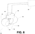
- FIG. 6 illustrates an embodiment of pressure fluctuation valve 24.
- pressure fluctuation valve 24 includes a conduit 42, a diaphragm 44, a motor 46, and/or other components.
- the conduit 42 includes a first end 48 and a second end 50.
- the conduit 42 forms a flow path between first end 48 and second end 50.
- pressure fluctuation valve 24 is installed within a system configured to provide a pressurized flow of breathable gas to the airway of a subject such that the pressurized flow of breathable gas passes through the flow path between first end 48 and second end 50 ( e.g., upstream or downstream from the subject).
- the diaphragm 44 is formed as a thin member having a first surface 52 and a second surface 54.
- the diaphragm 44 is mounted pivotally to the inner surface of conduit 42 at an interface of diaphragm 44 with motor 46.
- the shape of first surface 52 and/or second surface 54 corresponds to the inner cross sections of conduit 42 such that as diaphragm 44 rotates about the pivotal engagement with motor 46 the first surface 52 and/or second surface 54 at least partially block the flow of gas through conduit 42.
- gas is allowed to flow through conduit 42 relatively unimpeded when diaphragm 44 first surface 52 and second surface 54 face the sidewalls of conduit 42.
- the diaphragm 44 is formed from a resiliently flexible material. In one embodiment, the flexibility of diaphragm 44 is controllable by running an electrical current through diaphragm 44.
- the motor 46 is configured to rotate diaphragm 44 within conduit 42. This causes the diaphragm 44 to disrupt the flow of gas through conduit 42 in such a manner that causes stochastic fluctuations in pressure at or near the airway of the subject. More specifically, as diaphragm 44 rotates within conduit 42, first surface 52 and/or second surface 54 blocks more or less gas (depending on its position), thereby causing the stochastic fluctuations. It will be appreciated that the "rotation" of diaphragm 44 is not necessarily full rotations about an axis. Instead, the "rotation" of diaphragm 44 may refer to oscillations back and forth in different rotational directions.
- the flexibility of diaphragm 44 contributes to the stochastic nature of the fluctuations, as diaphragm 44 is flexed by the flow of gas through conduit 42.
- the one or more aspects of the rotation of diaphragm 44 within conduit 42 are stochastic, which contributes to the stochastic nature of the fluctuations.
- the axis of rotation, the rate of rotation, the rotational acceleration, the positions at which direction of rotation is changed, and/or other aspects of the rotation of diaphragm 44 may be varied stochastically (e.g., through control and/or structure of motor 46).
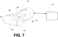
- FIG. 7 illustrates an embodiment of pressure fluctuation valve 24.
- pressure fluctuation valve 24 includes a conduit 56, a bellows 58, a motor 60, and/or other components.
- the conduit 56 includes a first end 62 and a second end 64.
- the conduit 56 forms a flow path between first end 62 and second end 64.
- pressure fluctuation valve 24 is installed within a system configured to provide a pressurized flow of breathable gas to the airway of a subject such that the pressurized flow of breathable gas passes through the flow path between first end 62 and second end 64 ( e.g ., upstream or downstream from the subject).
- the bellows 58 is configured to output gas from an output 66.
- the bellows 58 is expanded and contracted to take in (through an input not shown) and output (through output 66) gas by longitudinal motion of an end of bellows 58 opposite output 66 along a shaft 68.
- the output of gas into conduit 56 through output 66 tends to disrupt the flow of gas through conduit 56, thereby causing fluctuations of pressure at or near the airway of the subject.
- the motor 60 is configured to drive the end of bellows 58 opposite from output 66 back and forth along shaft 68.
- motor 60 includes a voice coil that creates a magnetic field providing the motive force that drives the end of bellows 58 back and forth along shaft 68.
- the imprecise nature of the bellows 58 and/or the interaction of the gas output from bellows 58 with the gas in conduit 56 may cause the fluctuations of pressure at or near the airway of the subject caused by pressure fluctuation valve 24 to be stochastic.
- the electrical current provided to drive motor 60 is varied randomly or pseudo-randomly. This may contribute to the stochastic nature of the fluctuations in pressure at or near the airway of the subject.
- FIG. 8 illustrates a method 70 of providing a pressurized flow of breathable gas to the airway of a subject.
- the operations of method 70 presented below are intended to be illustrative. In some embodiments, method 70 may be accomplished with one or more additional operations not described, and/or without one or more of the operations discussed. Additionally, the order in which the operations of method 70 are illustrated in FIG. 8 and described below is not intended to be limiting.
- a pressurized flow of breathable gas is generated.
- One or more gas parameters of the pressurized flow of breathable gas are controlled to provide therapeutic benefit to the subject.
- operation 72 is performed by a pressure generator similar to or the same as pressure generator 14 (shown in FIG. 1 and described above).
- operation 74 the pressurized flow of breathable gas is delivered to the airway of the subject.
- operation 74 is performed by a subject interface circuit similar to or the same as subject interface circuit 16 (shown in FIG. 1 and described above).
- a pressure fluctuation valve and/or the pressure generator are operated to create stochastic fluctuations in pressure of the pressurized flow of breathable gas at or near the airway of the subject.
- the pressure fluctuation valve may be similar to or the same as pressure fluctuation valve 24 (shown in FIGS. 1 and 5-7 , and described above).
- the one or more parameters may include one or more of, for example, a range of frequencies of the stochastic fluctuations, a mean or median frequency of the stochastic fluctuations, a range of magnitudes of the stochastic fluctuations, a mean or median magnitude of the stochastic fluctuations, a range of pressure levels within which the stochastic fluctuations occur, a maximum deviation away from the mean pressure level, and/or other parameters.
- operation 78 is performed by a user interface similar to or the same as user interface 20 (shown in FIG. 1 and described above).
- operation of the pressure fluctuation valve and/or the pressure generator is adjusted in accordance with the received user selection.
- operation 80 is performed by a fluctuation module similar to or the same as fluctuation module 38 (shown in FIG. 1 and described above).
Landscapes
- Health & Medical Sciences (AREA)
- Pulmonology (AREA)
- Life Sciences & Earth Sciences (AREA)
- Animal Behavior & Ethology (AREA)
- Anesthesiology (AREA)
- Biomedical Technology (AREA)
- Heart & Thoracic Surgery (AREA)
- Hematology (AREA)
- Emergency Medicine (AREA)
- Engineering & Computer Science (AREA)
- General Health & Medical Sciences (AREA)
- Public Health (AREA)
- Veterinary Medicine (AREA)
- Otolaryngology (AREA)
- Percussion Or Vibration Massage (AREA)
- Measurement Of The Respiration, Hearing Ability, Form, And Blood Characteristics Of Living Organisms (AREA)
- Devices For Medical Bathing And Washing (AREA)
Applications Claiming Priority (2)
| Application Number | Priority Date | Filing Date | Title |
|---|---|---|---|
| US37335410P | 2010-08-13 | 2010-08-13 | |
| PCT/IB2011/053581 WO2012020387A1 (en) | 2010-08-13 | 2011-08-11 | System and method for providing a pressurized flow of breathable gas to the airway of a subject with stochastic fluctuations |
Publications (2)
| Publication Number | Publication Date |
|---|---|
| EP2603266A1 EP2603266A1 (en) | 2013-06-19 |
| EP2603266B1 true EP2603266B1 (en) | 2017-05-24 |
Family
ID=44677988
Family Applications (1)
| Application Number | Title | Priority Date | Filing Date |
|---|---|---|---|
| EP11761137.6A Active EP2603266B1 (en) | 2010-08-13 | 2011-08-11 | System for providing a pressurized flow of breathable gas to the airway of a subject with stochastic fluctuations |
Country Status (8)
| Country | Link |
|---|---|
| US (1) | US20130133654A1 (enExample) |
| EP (1) | EP2603266B1 (enExample) |
| JP (1) | JP5872554B2 (enExample) |
| CN (1) | CN103068428B (enExample) |
| BR (1) | BR112013003293A2 (enExample) |
| IN (1) | IN2013CN01313A (enExample) |
| RU (1) | RU2584806C2 (enExample) |
| WO (1) | WO2012020387A1 (enExample) |
Families Citing this family (12)
| Publication number | Priority date | Publication date | Assignee | Title |
|---|---|---|---|---|
| WO2013175345A1 (en) * | 2012-05-22 | 2013-11-28 | Koninklijke Philips N.V. | Cough assistance and measurement system and method cross-reference to related applications |
| JP6288861B2 (ja) * | 2012-05-22 | 2018-03-07 | コーニンクレッカ フィリップス エヌ ヴェKoninklijke Philips N.V. | 成形された気流による圧補助療法のためのシステム及び方法 |
| US20140000606A1 (en) * | 2012-07-02 | 2014-01-02 | Nellcor Puritan Bennett Llc | Methods and systems for mimicking fluctuations in delivered flow and/or pressure during ventilation |
| CA2920624C (en) * | 2013-08-09 | 2020-04-14 | Advanced Cooling Therapy, Llc | Systems and methods for providing ventilation |
| EP4205787B1 (en) * | 2013-09-04 | 2026-01-14 | Fisher & Paykel Healthcare Limited | Improvements to flow therapy |
| EP3116578B1 (en) * | 2014-03-11 | 2019-05-08 | Koninklijke Philips N.V. | Compact dual limb diaphragm valve system |
| WO2016079703A1 (en) * | 2014-11-20 | 2016-05-26 | Koninklijke Philips N.V. | Non-invasive ventilation with high frequency oscillations |
| WO2016115465A1 (en) | 2015-01-16 | 2016-07-21 | Western Michigan University Research Foundation | Dual pressure respiratory assistance device |
| US11951251B2 (en) | 2018-04-05 | 2024-04-09 | Anna John | Dual-pressure respiratory assistance device |
| US12214139B2 (en) | 2018-11-02 | 2025-02-04 | University Of Cincinnati | Pulsating positive airway pressure devices and methods of use |
| US12491331B2 (en) | 2021-04-30 | 2025-12-09 | Stephen John | Dual-pressure respiratory assistance device |
| CN118593850A (zh) * | 2023-03-05 | 2024-09-06 | 深圳迈瑞生物医疗电子股份有限公司 | 一种麻醉机、呼吸支持设备和通气控制方法 |
Family Cites Families (12)
| Publication number | Priority date | Publication date | Assignee | Title |
|---|---|---|---|---|
| US4592349A (en) * | 1981-08-10 | 1986-06-03 | Bird F M | Ventilator having an oscillatory inspiratory phase and method |
| US5165398A (en) * | 1989-12-08 | 1992-11-24 | Bird F M | Ventilator and oscillator for use therewith and method |
| US6257234B1 (en) * | 1998-08-21 | 2001-07-10 | Respironics, Inc. | Apparatus and method for determining respiratory mechanics of a patient and for controlling a ventilator based thereon |
| US6708690B1 (en) | 1999-09-03 | 2004-03-23 | Respironics, Inc. | Apparatus and method for providing high frequency variable pressure to a patient |
| RU2164805C1 (ru) * | 1999-10-08 | 2001-04-10 | Открытое акционерное общество Акционерная компания "Туламашзавод" | Устройство для дыхательных упражнений |
| SE0002849D0 (sv) * | 2000-08-08 | 2000-08-08 | Siemens Elema Ab | Ventilator |
| US7478634B2 (en) * | 2002-09-17 | 2009-01-20 | Jam Mohammad R | Respiratory booster machine and method for enhancing ventilation |
| US6929007B2 (en) * | 2003-09-08 | 2005-08-16 | J.H. Emerson Company | Insufflation-exsufflation system with percussive assist for removal of broncho-pulmonary secretions |
| SE529328C2 (sv) * | 2005-11-15 | 2007-07-10 | Johan Stenberg | Styrsystem samt metod för styrning av elektromagnetiskt drivna pumpar |
| ITMI20061755A1 (it) * | 2006-09-14 | 2008-03-15 | Milano Politecnico | Apparato di supporto respiratorio e rilevamento non invasivo di dereclutamento alveolare per pazienti con insufficenze respiratorie |
| US8051854B2 (en) * | 2006-09-15 | 2011-11-08 | Comedica Incorporated | Continuous high-frequency oscillation breathing treatment apparatus |
| CN102046232B (zh) * | 2008-04-10 | 2014-07-02 | 西雅图儿童医院d/b/a西雅图儿童研究所 | 利用气泡的宽带、低频、高幅、长持续时间、振荡气道压力呼吸设备及方法 |
-
2011
- 2011-08-11 RU RU2013110816/14A patent/RU2584806C2/ru not_active IP Right Cessation
- 2011-08-11 WO PCT/IB2011/053581 patent/WO2012020387A1/en not_active Ceased
- 2011-08-11 US US13/814,598 patent/US20130133654A1/en not_active Abandoned
- 2011-08-11 IN IN1313CHN2013 patent/IN2013CN01313A/en unknown
- 2011-08-11 JP JP2013523695A patent/JP5872554B2/ja not_active Expired - Fee Related
- 2011-08-11 EP EP11761137.6A patent/EP2603266B1/en active Active
- 2011-08-11 CN CN201180039029.5A patent/CN103068428B/zh active Active
- 2011-08-11 BR BR112013003293A patent/BR112013003293A2/pt not_active IP Right Cessation
Also Published As
| Publication number | Publication date |
|---|---|
| WO2012020387A1 (en) | 2012-02-16 |
| EP2603266A1 (en) | 2013-06-19 |
| JP2013533087A (ja) | 2013-08-22 |
| US20130133654A1 (en) | 2013-05-30 |
| RU2584806C2 (ru) | 2016-05-20 |
| CN103068428B (zh) | 2016-01-13 |
| IN2013CN01313A (enExample) | 2015-08-07 |
| JP5872554B2 (ja) | 2016-03-01 |
| BR112013003293A2 (pt) | 2019-09-24 |
| RU2013110816A (ru) | 2014-09-20 |
| CN103068428A (zh) | 2013-04-24 |
Similar Documents
| Publication | Publication Date | Title |
|---|---|---|
| EP2603266B1 (en) | System for providing a pressurized flow of breathable gas to the airway of a subject with stochastic fluctuations | |
| CN102762248B (zh) | 一种用于提供支持治疗并同时确定由接受压力支持治疗的受试者呼出的气体分子的浓度的系统 | |
| CN104936643B (zh) | 与通气机集成的用于肺内叩击通气的系统和方法 | |
| EP2827930B1 (en) | System for controlling insufflation pressure during inexsufflation | |
| EP2945677B1 (en) | System for controlling airway gas parameters during high frequency positive pressure ventilation | |
| US9642976B2 (en) | Systems and methods for intra-pulmonary percussive ventilation integrated in a ventilator | |
| EP2934639B1 (en) | Inspiratory pressure control in volume mode ventilation | |
| EP3116578B1 (en) | Compact dual limb diaphragm valve system | |
| US20150075529A1 (en) | System and method for pressure support therapy with shaped airflow | |
| WO2016079703A1 (en) | Non-invasive ventilation with high frequency oscillations | |
| CN103260682A (zh) | 取决于呼吸速率的呼吸辅助 | |
| EP3209357B1 (en) | System for controlling leak | |
| RU2664593C2 (ru) | Система для подачи импульсов давления в дыхательные пути субъекта | |
| US11052207B2 (en) | Gas sensing apparatus |
Legal Events
| Date | Code | Title | Description |
|---|---|---|---|
| PUAI | Public reference made under article 153(3) epc to a published international application that has entered the european phase |
Free format text: ORIGINAL CODE: 0009012 |
|
| 17P | Request for examination filed |
Effective date: 20130313 |
|
| AK | Designated contracting states |
Kind code of ref document: A1 Designated state(s): AL AT BE BG CH CY CZ DE DK EE ES FI FR GB GR HR HU IE IS IT LI LT LU LV MC MK MT NL NO PL PT RO RS SE SI SK SM TR |
|
| RAP1 | Party data changed (applicant data changed or rights of an application transferred) |
Owner name: KONINKLIJKE PHILIPS N.V. |
|
| DAX | Request for extension of the european patent (deleted) | ||
| 17Q | First examination report despatched |
Effective date: 20151006 |
|
| GRAP | Despatch of communication of intention to grant a patent |
Free format text: ORIGINAL CODE: EPIDOSNIGR1 |
|
| INTG | Intention to grant announced |
Effective date: 20161212 |
|
| RIN1 | Information on inventor provided before grant (corrected) |
Inventor name: ARCILLA, MABINI Inventor name: GARDE, SMITA Inventor name: MADISON, MICHAEL EDWARD Inventor name: AHMAD, SAMIR |
|
| GRAS | Grant fee paid |
Free format text: ORIGINAL CODE: EPIDOSNIGR3 |
|
| GRAA | (expected) grant |
Free format text: ORIGINAL CODE: 0009210 |
|
| AK | Designated contracting states |
Kind code of ref document: B1 Designated state(s): AL AT BE BG CH CY CZ DE DK EE ES FI FR GB GR HR HU IE IS IT LI LT LU LV MC MK MT NL NO PL PT RO RS SE SI SK SM TR |
|
| REG | Reference to a national code |
Ref country code: GB Ref legal event code: FG4D |
|
| REG | Reference to a national code |
Ref country code: CH Ref legal event code: EP |
|
| REG | Reference to a national code |
Ref country code: IE Ref legal event code: FG4D |
|
| REG | Reference to a national code |
Ref country code: AT Ref legal event code: REF Ref document number: 895706 Country of ref document: AT Kind code of ref document: T Effective date: 20170615 |
|
| REG | Reference to a national code |
Ref country code: DE Ref legal event code: R096 Ref document number: 602011038214 Country of ref document: DE |
|
| REG | Reference to a national code |
Ref country code: FR Ref legal event code: PLFP Year of fee payment: 7 |
|
| REG | Reference to a national code |
Ref country code: NL Ref legal event code: MP Effective date: 20170524 |
|
| REG | Reference to a national code |
Ref country code: LT Ref legal event code: MG4D |
|
| REG | Reference to a national code |
Ref country code: AT Ref legal event code: MK05 Ref document number: 895706 Country of ref document: AT Kind code of ref document: T Effective date: 20170524 |
|
| PG25 | Lapsed in a contracting state [announced via postgrant information from national office to epo] |
Ref country code: LT Free format text: LAPSE BECAUSE OF FAILURE TO SUBMIT A TRANSLATION OF THE DESCRIPTION OR TO PAY THE FEE WITHIN THE PRESCRIBED TIME-LIMIT Effective date: 20170524 Ref country code: ES Free format text: LAPSE BECAUSE OF FAILURE TO SUBMIT A TRANSLATION OF THE DESCRIPTION OR TO PAY THE FEE WITHIN THE PRESCRIBED TIME-LIMIT Effective date: 20170524 Ref country code: GR Free format text: LAPSE BECAUSE OF FAILURE TO SUBMIT A TRANSLATION OF THE DESCRIPTION OR TO PAY THE FEE WITHIN THE PRESCRIBED TIME-LIMIT Effective date: 20170825 Ref country code: HR Free format text: LAPSE BECAUSE OF FAILURE TO SUBMIT A TRANSLATION OF THE DESCRIPTION OR TO PAY THE FEE WITHIN THE PRESCRIBED TIME-LIMIT Effective date: 20170524 Ref country code: FI Free format text: LAPSE BECAUSE OF FAILURE TO SUBMIT A TRANSLATION OF THE DESCRIPTION OR TO PAY THE FEE WITHIN THE PRESCRIBED TIME-LIMIT Effective date: 20170524 Ref country code: AT Free format text: LAPSE BECAUSE OF FAILURE TO SUBMIT A TRANSLATION OF THE DESCRIPTION OR TO PAY THE FEE WITHIN THE PRESCRIBED TIME-LIMIT Effective date: 20170524 Ref country code: NO Free format text: LAPSE BECAUSE OF FAILURE TO SUBMIT A TRANSLATION OF THE DESCRIPTION OR TO PAY THE FEE WITHIN THE PRESCRIBED TIME-LIMIT Effective date: 20170824 |
|
| PG25 | Lapsed in a contracting state [announced via postgrant information from national office to epo] |
Ref country code: IS Free format text: LAPSE BECAUSE OF FAILURE TO SUBMIT A TRANSLATION OF THE DESCRIPTION OR TO PAY THE FEE WITHIN THE PRESCRIBED TIME-LIMIT Effective date: 20170924 Ref country code: RS Free format text: LAPSE BECAUSE OF FAILURE TO SUBMIT A TRANSLATION OF THE DESCRIPTION OR TO PAY THE FEE WITHIN THE PRESCRIBED TIME-LIMIT Effective date: 20170524 Ref country code: LV Free format text: LAPSE BECAUSE OF FAILURE TO SUBMIT A TRANSLATION OF THE DESCRIPTION OR TO PAY THE FEE WITHIN THE PRESCRIBED TIME-LIMIT Effective date: 20170524 Ref country code: NL Free format text: LAPSE BECAUSE OF FAILURE TO SUBMIT A TRANSLATION OF THE DESCRIPTION OR TO PAY THE FEE WITHIN THE PRESCRIBED TIME-LIMIT Effective date: 20170524 Ref country code: BG Free format text: LAPSE BECAUSE OF FAILURE TO SUBMIT A TRANSLATION OF THE DESCRIPTION OR TO PAY THE FEE WITHIN THE PRESCRIBED TIME-LIMIT Effective date: 20170824 Ref country code: SE Free format text: LAPSE BECAUSE OF FAILURE TO SUBMIT A TRANSLATION OF THE DESCRIPTION OR TO PAY THE FEE WITHIN THE PRESCRIBED TIME-LIMIT Effective date: 20170524 |
|
| PG25 | Lapsed in a contracting state [announced via postgrant information from national office to epo] |
Ref country code: EE Free format text: LAPSE BECAUSE OF FAILURE TO SUBMIT A TRANSLATION OF THE DESCRIPTION OR TO PAY THE FEE WITHIN THE PRESCRIBED TIME-LIMIT Effective date: 20170524 Ref country code: SK Free format text: LAPSE BECAUSE OF FAILURE TO SUBMIT A TRANSLATION OF THE DESCRIPTION OR TO PAY THE FEE WITHIN THE PRESCRIBED TIME-LIMIT Effective date: 20170524 Ref country code: DK Free format text: LAPSE BECAUSE OF FAILURE TO SUBMIT A TRANSLATION OF THE DESCRIPTION OR TO PAY THE FEE WITHIN THE PRESCRIBED TIME-LIMIT Effective date: 20170524 Ref country code: RO Free format text: LAPSE BECAUSE OF FAILURE TO SUBMIT A TRANSLATION OF THE DESCRIPTION OR TO PAY THE FEE WITHIN THE PRESCRIBED TIME-LIMIT Effective date: 20170524 Ref country code: CZ Free format text: LAPSE BECAUSE OF FAILURE TO SUBMIT A TRANSLATION OF THE DESCRIPTION OR TO PAY THE FEE WITHIN THE PRESCRIBED TIME-LIMIT Effective date: 20170524 |
|
| REG | Reference to a national code |
Ref country code: DE Ref legal event code: R097 Ref document number: 602011038214 Country of ref document: DE |
|
| PG25 | Lapsed in a contracting state [announced via postgrant information from national office to epo] |
Ref country code: IT Free format text: LAPSE BECAUSE OF FAILURE TO SUBMIT A TRANSLATION OF THE DESCRIPTION OR TO PAY THE FEE WITHIN THE PRESCRIBED TIME-LIMIT Effective date: 20170524 Ref country code: SM Free format text: LAPSE BECAUSE OF FAILURE TO SUBMIT A TRANSLATION OF THE DESCRIPTION OR TO PAY THE FEE WITHIN THE PRESCRIBED TIME-LIMIT Effective date: 20170524 Ref country code: PL Free format text: LAPSE BECAUSE OF FAILURE TO SUBMIT A TRANSLATION OF THE DESCRIPTION OR TO PAY THE FEE WITHIN THE PRESCRIBED TIME-LIMIT Effective date: 20170524 |
|
| REG | Reference to a national code |
Ref country code: CH Ref legal event code: PL |
|
| PG25 | Lapsed in a contracting state [announced via postgrant information from national office to epo] |
Ref country code: MC Free format text: LAPSE BECAUSE OF FAILURE TO SUBMIT A TRANSLATION OF THE DESCRIPTION OR TO PAY THE FEE WITHIN THE PRESCRIBED TIME-LIMIT Effective date: 20170524 |
|
| PLBE | No opposition filed within time limit |
Free format text: ORIGINAL CODE: 0009261 |
|
| STAA | Information on the status of an ep patent application or granted ep patent |
Free format text: STATUS: NO OPPOSITION FILED WITHIN TIME LIMIT |
|
| PG25 | Lapsed in a contracting state [announced via postgrant information from national office to epo] |
Ref country code: CH Free format text: LAPSE BECAUSE OF NON-PAYMENT OF DUE FEES Effective date: 20170831 Ref country code: LI Free format text: LAPSE BECAUSE OF NON-PAYMENT OF DUE FEES Effective date: 20170831 |
|
| 26N | No opposition filed |
Effective date: 20180227 |
|
| REG | Reference to a national code |
Ref country code: IE Ref legal event code: MM4A |
|
| PG25 | Lapsed in a contracting state [announced via postgrant information from national office to epo] |
Ref country code: SI Free format text: LAPSE BECAUSE OF FAILURE TO SUBMIT A TRANSLATION OF THE DESCRIPTION OR TO PAY THE FEE WITHIN THE PRESCRIBED TIME-LIMIT Effective date: 20170524 |
|
| REG | Reference to a national code |
Ref country code: BE Ref legal event code: MM Effective date: 20170831 |
|
| PG25 | Lapsed in a contracting state [announced via postgrant information from national office to epo] |
Ref country code: LU Free format text: LAPSE BECAUSE OF NON-PAYMENT OF DUE FEES Effective date: 20170811 |
|
| PG25 | Lapsed in a contracting state [announced via postgrant information from national office to epo] |
Ref country code: IE Free format text: LAPSE BECAUSE OF NON-PAYMENT OF DUE FEES Effective date: 20170811 |
|
| REG | Reference to a national code |
Ref country code: FR Ref legal event code: PLFP Year of fee payment: 8 |
|
| PG25 | Lapsed in a contracting state [announced via postgrant information from national office to epo] |
Ref country code: BE Free format text: LAPSE BECAUSE OF NON-PAYMENT OF DUE FEES Effective date: 20170831 |
|
| PG25 | Lapsed in a contracting state [announced via postgrant information from national office to epo] |
Ref country code: MT Free format text: LAPSE BECAUSE OF NON-PAYMENT OF DUE FEES Effective date: 20170811 |
|
| PG25 | Lapsed in a contracting state [announced via postgrant information from national office to epo] |
Ref country code: HU Free format text: LAPSE BECAUSE OF FAILURE TO SUBMIT A TRANSLATION OF THE DESCRIPTION OR TO PAY THE FEE WITHIN THE PRESCRIBED TIME-LIMIT; INVALID AB INITIO Effective date: 20110811 |
|
| PG25 | Lapsed in a contracting state [announced via postgrant information from national office to epo] |
Ref country code: CY Free format text: LAPSE BECAUSE OF NON-PAYMENT OF DUE FEES Effective date: 20170524 |
|
| PG25 | Lapsed in a contracting state [announced via postgrant information from national office to epo] |
Ref country code: MK Free format text: LAPSE BECAUSE OF FAILURE TO SUBMIT A TRANSLATION OF THE DESCRIPTION OR TO PAY THE FEE WITHIN THE PRESCRIBED TIME-LIMIT Effective date: 20170524 |
|
| PG25 | Lapsed in a contracting state [announced via postgrant information from national office to epo] |
Ref country code: TR Free format text: LAPSE BECAUSE OF FAILURE TO SUBMIT A TRANSLATION OF THE DESCRIPTION OR TO PAY THE FEE WITHIN THE PRESCRIBED TIME-LIMIT Effective date: 20170524 |
|
| PG25 | Lapsed in a contracting state [announced via postgrant information from national office to epo] |
Ref country code: PT Free format text: LAPSE BECAUSE OF FAILURE TO SUBMIT A TRANSLATION OF THE DESCRIPTION OR TO PAY THE FEE WITHIN THE PRESCRIBED TIME-LIMIT Effective date: 20170524 |
|
| PG25 | Lapsed in a contracting state [announced via postgrant information from national office to epo] |
Ref country code: AL Free format text: LAPSE BECAUSE OF FAILURE TO SUBMIT A TRANSLATION OF THE DESCRIPTION OR TO PAY THE FEE WITHIN THE PRESCRIBED TIME-LIMIT Effective date: 20170524 |
|
| PGFP | Annual fee paid to national office [announced via postgrant information from national office to epo] |
Ref country code: DE Payment date: 20240828 Year of fee payment: 14 |
|
| PGFP | Annual fee paid to national office [announced via postgrant information from national office to epo] |
Ref country code: GB Payment date: 20240827 Year of fee payment: 14 |
|
| PGFP | Annual fee paid to national office [announced via postgrant information from national office to epo] |
Ref country code: FR Payment date: 20240826 Year of fee payment: 14 |
|
| REG | Reference to a national code |
Ref country code: DE Ref legal event code: R119 Ref document number: 602011038214 Country of ref document: DE |