EP2945677B1 - System for controlling airway gas parameters during high frequency positive pressure ventilation - Google Patents
System for controlling airway gas parameters during high frequency positive pressure ventilation Download PDFInfo
- Publication number
- EP2945677B1 EP2945677B1 EP14701626.5A EP14701626A EP2945677B1 EP 2945677 B1 EP2945677 B1 EP 2945677B1 EP 14701626 A EP14701626 A EP 14701626A EP 2945677 B1 EP2945677 B1 EP 2945677B1
- Authority
- EP
- European Patent Office
- Prior art keywords
- peak
- pressure
- airway
- high frequency
- gas
- Prior art date
- Legal status (The legal status is an assumption and is not a legal conclusion. Google has not performed a legal analysis and makes no representation as to the accuracy of the status listed.)
- Active
Links
Images


Classifications
-
- A—HUMAN NECESSITIES
- A61—MEDICAL OR VETERINARY SCIENCE; HYGIENE
- A61M—DEVICES FOR INTRODUCING MEDIA INTO, OR ONTO, THE BODY; DEVICES FOR TRANSDUCING BODY MEDIA OR FOR TAKING MEDIA FROM THE BODY; DEVICES FOR PRODUCING OR ENDING SLEEP OR STUPOR
- A61M16/00—Devices for influencing the respiratory system of patients by gas treatment, e.g. mouth-to-mouth respiration; Tracheal tubes
- A61M16/0003—Accessories therefor, e.g. sensors, vibrators, negative pressure
- A61M16/0009—Accessories therefor, e.g. sensors, vibrators, negative pressure with sub-atmospheric pressure, e.g. during expiration
-
- A—HUMAN NECESSITIES
- A61—MEDICAL OR VETERINARY SCIENCE; HYGIENE
- A61M—DEVICES FOR INTRODUCING MEDIA INTO, OR ONTO, THE BODY; DEVICES FOR TRANSDUCING BODY MEDIA OR FOR TAKING MEDIA FROM THE BODY; DEVICES FOR PRODUCING OR ENDING SLEEP OR STUPOR
- A61M16/00—Devices for influencing the respiratory system of patients by gas treatment, e.g. mouth-to-mouth respiration; Tracheal tubes
- A61M16/0003—Accessories therefor, e.g. sensors, vibrators, negative pressure
-
- A—HUMAN NECESSITIES
- A61—MEDICAL OR VETERINARY SCIENCE; HYGIENE
- A61M—DEVICES FOR INTRODUCING MEDIA INTO, OR ONTO, THE BODY; DEVICES FOR TRANSDUCING BODY MEDIA OR FOR TAKING MEDIA FROM THE BODY; DEVICES FOR PRODUCING OR ENDING SLEEP OR STUPOR
- A61M16/00—Devices for influencing the respiratory system of patients by gas treatment, e.g. mouth-to-mouth respiration; Tracheal tubes
- A61M16/0057—Pumps therefor
- A61M16/0066—Blowers or centrifugal pumps
- A61M16/0069—Blowers or centrifugal pumps the speed thereof being controlled by respiratory parameters, e.g. by inhalation
-
- A—HUMAN NECESSITIES
- A61—MEDICAL OR VETERINARY SCIENCE; HYGIENE
- A61M—DEVICES FOR INTRODUCING MEDIA INTO, OR ONTO, THE BODY; DEVICES FOR TRANSDUCING BODY MEDIA OR FOR TAKING MEDIA FROM THE BODY; DEVICES FOR PRODUCING OR ENDING SLEEP OR STUPOR
- A61M16/00—Devices for influencing the respiratory system of patients by gas treatment, e.g. mouth-to-mouth respiration; Tracheal tubes
- A61M16/0096—High frequency jet ventilation
-
- A—HUMAN NECESSITIES
- A61—MEDICAL OR VETERINARY SCIENCE; HYGIENE
- A61M—DEVICES FOR INTRODUCING MEDIA INTO, OR ONTO, THE BODY; DEVICES FOR TRANSDUCING BODY MEDIA OR FOR TAKING MEDIA FROM THE BODY; DEVICES FOR PRODUCING OR ENDING SLEEP OR STUPOR
- A61M16/00—Devices for influencing the respiratory system of patients by gas treatment, e.g. mouth-to-mouth respiration; Tracheal tubes
- A61M16/021—Devices for influencing the respiratory system of patients by gas treatment, e.g. mouth-to-mouth respiration; Tracheal tubes operated by electrical means
- A61M16/022—Control means therefor
- A61M16/024—Control means therefor including calculation means, e.g. using a processor
-
- A—HUMAN NECESSITIES
- A61—MEDICAL OR VETERINARY SCIENCE; HYGIENE
- A61M—DEVICES FOR INTRODUCING MEDIA INTO, OR ONTO, THE BODY; DEVICES FOR TRANSDUCING BODY MEDIA OR FOR TAKING MEDIA FROM THE BODY; DEVICES FOR PRODUCING OR ENDING SLEEP OR STUPOR
- A61M16/00—Devices for influencing the respiratory system of patients by gas treatment, e.g. mouth-to-mouth respiration; Tracheal tubes
- A61M16/20—Valves specially adapted to medical respiratory devices
- A61M16/201—Controlled valves
- A61M16/202—Controlled valves electrically actuated
- A61M16/203—Proportional
- A61M16/205—Proportional used for exhalation control
-
- A—HUMAN NECESSITIES
- A61—MEDICAL OR VETERINARY SCIENCE; HYGIENE
- A61M—DEVICES FOR INTRODUCING MEDIA INTO, OR ONTO, THE BODY; DEVICES FOR TRANSDUCING BODY MEDIA OR FOR TAKING MEDIA FROM THE BODY; DEVICES FOR PRODUCING OR ENDING SLEEP OR STUPOR
- A61M16/00—Devices for influencing the respiratory system of patients by gas treatment, e.g. mouth-to-mouth respiration; Tracheal tubes
- A61M16/20—Valves specially adapted to medical respiratory devices
- A61M16/208—Non-controlled one-way valves, e.g. exhalation, check, pop-off non-rebreathing valves
-
- A—HUMAN NECESSITIES
- A61—MEDICAL OR VETERINARY SCIENCE; HYGIENE
- A61M—DEVICES FOR INTRODUCING MEDIA INTO, OR ONTO, THE BODY; DEVICES FOR TRANSDUCING BODY MEDIA OR FOR TAKING MEDIA FROM THE BODY; DEVICES FOR PRODUCING OR ENDING SLEEP OR STUPOR
- A61M16/00—Devices for influencing the respiratory system of patients by gas treatment, e.g. mouth-to-mouth respiration; Tracheal tubes
- A61M16/0057—Pumps therefor
-
- A—HUMAN NECESSITIES
- A61—MEDICAL OR VETERINARY SCIENCE; HYGIENE
- A61M—DEVICES FOR INTRODUCING MEDIA INTO, OR ONTO, THE BODY; DEVICES FOR TRANSDUCING BODY MEDIA OR FOR TAKING MEDIA FROM THE BODY; DEVICES FOR PRODUCING OR ENDING SLEEP OR STUPOR
- A61M16/00—Devices for influencing the respiratory system of patients by gas treatment, e.g. mouth-to-mouth respiration; Tracheal tubes
- A61M16/20—Valves specially adapted to medical respiratory devices
-
- A—HUMAN NECESSITIES
- A61—MEDICAL OR VETERINARY SCIENCE; HYGIENE
- A61M—DEVICES FOR INTRODUCING MEDIA INTO, OR ONTO, THE BODY; DEVICES FOR TRANSDUCING BODY MEDIA OR FOR TAKING MEDIA FROM THE BODY; DEVICES FOR PRODUCING OR ENDING SLEEP OR STUPOR
- A61M16/00—Devices for influencing the respiratory system of patients by gas treatment, e.g. mouth-to-mouth respiration; Tracheal tubes
- A61M16/0003—Accessories therefor, e.g. sensors, vibrators, negative pressure
- A61M2016/0027—Accessories therefor, e.g. sensors, vibrators, negative pressure pressure meter
-
- A—HUMAN NECESSITIES
- A61—MEDICAL OR VETERINARY SCIENCE; HYGIENE
- A61M—DEVICES FOR INTRODUCING MEDIA INTO, OR ONTO, THE BODY; DEVICES FOR TRANSDUCING BODY MEDIA OR FOR TAKING MEDIA FROM THE BODY; DEVICES FOR PRODUCING OR ENDING SLEEP OR STUPOR
- A61M16/00—Devices for influencing the respiratory system of patients by gas treatment, e.g. mouth-to-mouth respiration; Tracheal tubes
- A61M16/0003—Accessories therefor, e.g. sensors, vibrators, negative pressure
- A61M2016/003—Accessories therefor, e.g. sensors, vibrators, negative pressure with a flowmeter
-
- A—HUMAN NECESSITIES
- A61—MEDICAL OR VETERINARY SCIENCE; HYGIENE
- A61M—DEVICES FOR INTRODUCING MEDIA INTO, OR ONTO, THE BODY; DEVICES FOR TRANSDUCING BODY MEDIA OR FOR TAKING MEDIA FROM THE BODY; DEVICES FOR PRODUCING OR ENDING SLEEP OR STUPOR
- A61M2205/00—General characteristics of the apparatus
- A61M2205/33—Controlling, regulating or measuring
- A61M2205/3331—Pressure; Flow
- A61M2205/3334—Measuring or controlling the flow rate
-
- A—HUMAN NECESSITIES
- A61—MEDICAL OR VETERINARY SCIENCE; HYGIENE
- A61M—DEVICES FOR INTRODUCING MEDIA INTO, OR ONTO, THE BODY; DEVICES FOR TRANSDUCING BODY MEDIA OR FOR TAKING MEDIA FROM THE BODY; DEVICES FOR PRODUCING OR ENDING SLEEP OR STUPOR
- A61M2205/00—General characteristics of the apparatus
- A61M2205/50—General characteristics of the apparatus with microprocessors or computers
Definitions
- the present disclosure pertains to a high frequency positive pressure ventilation system.
- the system may be configured to maintain a time averaged airway pressure level at a target time averaged airway pressure level and/or a peak-to-peak pressure difference at a target peak-to-peak pressure difference.
- High frequency ventilators are known. High frequency ventilators are used for delivery of low tidal volumes of breathable gas.
- High frequency oscillatory ventilation HFOV is a widely used type high frequency ventilation that uses a piston based system for generating positive and negative pressure oscillations.
- a user In addition to manually selecting the frequency of the high frequency ventilation, a user typically manually selects a peak-to-peak pressure and a mean airway pressure. The peak-to-peak pressure and the mean airway pressure determine a delivered tidal volume and an oxygenation of a patient's lungs.
- peak-to-peak pressure is controlled by piston settings and the mean airway pressure is controlled by a balloon valve in the expiratory limb. The user manually adjusts the settings of this valve as the conditions in the patient's lungs change.
- Document WO 2012/085792 A2 relates to a ventilator system including an integrated blower.
- the ventilator system includes: an inspiration port for connection to an inspiratory limb of a dual-limb patient circuit, and an expiration port for connection to an expiratory limb of the dual-limb patient circuit; a gas delivery device connected to the inspiration port to supply a pressurized flow of gas to the inspiration port to generate a positive pressure; and a blower having an inlet that is operatively connected to the expiration port and configured to be controlled to selectively supply a negative pressure level between 4 and 120 cmH 2 O to the expiration port, and an outlet to exhaust gas received from the expiration port.
- the ventilator system described therein includes a blower to generate positive pressure/flow to augment flow for noninvasive ventilation.
- the word "unitary” means a component is created as a single piece or unit. That is, a component that includes pieces that are created separately and then coupled together as a unit is not a “unitary” component or body.
- the statement that two or more parts or components "engage” one another shall mean that the parts exert a force against one another either directly or through one or more intermediate parts or components.
- the term “number” shall mean one or an integer greater than one (i.e., a plurality).
- FIG. 1 schematically illustrates a high frequency positive pressure ventilation system 10.
- system 10 comprises one or more of a ventilator 12 that includes an inspiratory subsystem 14, an expiratory subsystem 16, a respiratory circuit 18, a processor 20, electronic storage (not shown), and/or other components.
- system 10 is configured to provide a subject 22 with ventilation in accordance with a high frequency positive pressure ventilation therapy regime.
- System 10 is configured to maintain a time averaged airway pressure level (e.g., mean airway pressure) and/or a peak-to-peak pressure level at target levels over a series of inhalations and/or exhalations.
- System 10 is configured to automatically maintain the time averaged airway pressure level and/or the peak-to-peak pressure level, reducing and/or eliminating the need for manual adjustments during high frequency positive pressure ventilation. Automatic control provides timely parameter adjustments as lung and respiratory conditions change during treatment.
- Respiratory circuit 18 is configured to deliver a pressurized flow of breathable gas to the airway of the subject in order to ventilate subject 22.
- Respiratory circuit 18 includes one or more of an inspiratory conduit 24, an expiratory circuit 26, a subject interface 28, and/or other components.
- Inspiratory conduit 24 is configured to deliver gas for inspiration from inspiratory subsystem 14 to subject interface 28.
- Expiratory conduit is configured to communicate expired gas to expiratory subsystem 16 from subject interface 28.
- Conduits 24 and/or 26 may be flexible, and/or may be selectively removable from subject interface 28, inspiratory subsystem 14, and/or expiratory subsystem 16.
- Subject interface 28 includes a subject interface appliance 30 that communicates with the airway of subject 22.
- Subject interface appliance 30 may include an invasive appliance, such as an endotracheal tube or other invasive appliance, or a non-invasive appliance, such as a mask or other non-invasive appliance.
- Inspiratory subsystem 14 is configured to provide a pressurized flow of breathable gas for delivery to the airway of subject 22 during inspiration.
- Inspiratory subsystem 14 is configured such that one or more gas parameters of the pressurized flow of breathable gas are controlled in accordance with a therapy regime.
- the one or more gas parameters may include, for example, one or more of flow, pressure, humidity, velocity, acceleration, and/or other parameters.
- system 10 is a device dedicated to high frequency positive pressure ventilation.
- Inspiratory subsystem 14 is a ventilator and/or positive airway pressure device configured to provide therapy other than and/or in addition to high frequency positive pressure ventilation.
- Inspiratory subsystem 14 may include any device, such as, for example, a pump, compressed gas source, blower, piston, or bellows, that is capable of providing a flow of gas at an elevated pressure.
- gas other than ambient atmospheric air e.g., oxygen enriched gas, medicament, and/or other gases
- gas other than ambient atmospheric air e.g., oxygen enriched gas, medicament, and/or other gases
- Expiratory subsystem 16 is configured to exhaust gas from the airway of subject 22 and/or respiratory circuit 18 to effect expiration of gas.
- Expiratory subsystem 16 may include one or more of an outlet 32, an expiratory flow generator 34, an exhalation valve 36, and/or other components.
- Outlet 32 is configured to release expired gas from system 10. This may include releasing gas directly into ambient atmosphere, or releasing gas into a filter or other treatment component to treat the gas prior to release.
- the expiratory flow generator 34 is configured to draw gas through expiration conduit 26 and out outlet 32.
- the expiratory flow generator 34 may include, for example, a blower, a bellows, and/or other devices or mechanisms suitable for generating a flow of gas from expiration conduit 26 out through outlet 32.
- the rate at which expiratory flow generator 34 creates the flow may be adjustable by adjusting the operation of expiratory flow generator 34. For example, a rotary speed of a blower may be adjusted to draw more or less gas out through outlet 32.
- Exhalation valve 36 is configured to selectively place expiratory conduit 26 in communication with expiratory flow generator 34.
- exhalation valve 36 may inhibit or completely shut off communication between expiratory conduit 26 and expiratory flow generator 34.
- pressure in the airway of subject 22 will tend to rise as gas from inspiratory subsystem 14 is delivered to subject 22 while little or no gas is permitted to be exhausted through expiratory subsystem 14.
- FIG. 2 illustrates exhalation valve 36 in a second position in which expiratory conduit 26 communicates with expiratory flow generator 34 through exhalation valve 36. This may cause pressure in the airway of subject 22 to fall, as gas from the airway of subject 22 is drawn out through expiratory conduit 26 and outlet 32.
- a leak port 38 may act as an inlet through which gas is drawn into expiratory flow generator 34.
- Leak port 38 may simply be a passive port ( e . g ., an opening, a flapper valve, and/or other passive ports), or may be actively opened as exhalation valve 36 is closed, and vice versa.
- exhalation valve 36 is not merely opened and closed, but may be opened and closed incrementally to allow relatively more or less gas to flow from expiratory conduit 26 to outlet 32.
- exhalation valve 36 and/or expiratory flow generator 34 pressure at the airway of subject 22 can be controlled while gas is delivered to the airway of subject 22 from inspiratory subsystem 14.
- the parameters (e . g ., pressure, flow, etc .) of the gas delivered from inspiratory subsystem 14 may be controlled dynamically in coordination with exhalation valve 36 and/or expiratory flow generator 34 to control airway pressure, or the inspiratory gas may be delivered substantially continuously and airway pressure controlled entirely or substantially entirely by adjusting operation of exhalation valve 36 and/or expiratory flow generator 34.
- expiratory flow generator 34 and/or exhalation valve 36 may be configured to adjust the airway pressure in accordance with a high frequency ventilation regime.
- the therapy regime may dictate that the airway pressure fluctuates over a series of pressure cycles in which a mean airway pressure is maintained. During these pressure cycles, the parameters such as frequency, pressure or flow amplitude, mean pressure, tidal volume, peak flow, and/or other parameters can be controlled through operation of expiratory flow generator 34 and/or exhalation valve 36.
- System 10 may include one or more sensors 40 configured to generate output signals conveying information related to one or more gas parameters of the gas within system 10.
- the one or more gas parameters may comprise flow, volume, pressure, a composition (e.g., concentration(s) of one or more constituents), temperature, humidity, acceleration, velocity, acoustics, changes in a parameter indicative of respiration, and/or other gas parameters.
- Sensors 40 may comprise one or more sensors that measure such parameters directly.
- Sensors 40 may comprise one or more sensors that generate output signals related to one or more parameters of the flow of gas indirectly. For example, one or more of sensors 40 may generate an output based on an operating parameter of expiratory flow generator 34 (e.g., motor current, voltage, rotational velocity, and/or other operating parameters), and/or other parameters.
- an operating parameter of expiratory flow generator 34 e.g., motor current, voltage, rotational velocity, and/or other operating parameters
- sensors 40 are illustrated at a single location within respiratory circuit 18, this is not intended to be limiting. Sensors 40 may include sensors disposed in a plurality of locations, such as for example, within expiratory flow generator 34, within (or in communication with) inspiratory subsystem 14, and/or other locations.
- Processor 20 is configured to provide information processing capabilities in system 10.
- processor 20 may comprise one or more of a digital processor, an analog processor, a digital circuit designed to process information, an analog circuit designed to process information, a state machine, and/or other mechanisms for electronically processing information.
- processor 20 is shown in FIG. 1 as a single entity, this is for illustrative purposes only.
- processor 20 may comprise a plurality of processing units. These processing units may be physically located within the same device, or processor 20 may represent processing functionality of a plurality of devices operating in coordination.
- processor 20 is configured to execute one or more computer program modules.
- the one or more computer program modules may comprise one or more of a parameter module 42, a target module 44, a control module 46, and/or other modules.
- Processor 20 may be configured to execute modules 42, 44, and/or 46 by software; hardware; firmware; some combination of software, hardware, and/or firmware; and/or other mechanisms for configuring processing capabilities on processor 24.
- modules 42, 44, and/or 46 are illustrated in FIG. 1 as being co-located within a single processing unit, in implementations in which processor 20 comprises multiple processing units, one or more of modules 42, 44, and/or 46 may be located remotely from the other modules.
- the description of the functionality provided by the different modules 42, 44, and/or 46 described below is for illustrative purposes, and is not intended to be limiting, as any of modules 42, 44, and/or 46 may provide more or less functionality than is described.
- processor 20 may be configured to execute one or more additional modules that may perform some or all of the functionality attributed below to one of modules 42, 44, and/or 46.
- Parameter module 42 is configured to determine one or more parameters within system 10.
- the one or more parameters within system 10 may comprise gas parameters related to the flow of breathable gas at or near the airway of subject 22, and/or other parameters.
- Parameter module 42 is configured to determine the one or more parameters based on the output signals of sensors 40, and/or other information.
- the information determined by parameter module 42 may be used for controlling expiratory flow generator 34, controlling exhalation valve 36, stored in electronic storage, and/or used for other uses.
- the one or more gas parameters of the pressurized flow of breathable gas may comprise, for example, one or more of a flow rate, a volume, a pressure, humidity, temperature, acceleration, velocity, and/or other gas parameters.
- parameter module 42 may be configured to determine the respiratory phase (e.g., inhalation, exhalation) and/or or high frequency pressure cycles during ventilation of subject 12.
- the respiratory phase may include the phase of the determinations made by parameter module 25 are based on the output signals from pressure cycles generated through control of inspriatory subsystem 14, expiratory flow generator 34 and/or exhalation valve 36.
- Parameter module 42 may be configured to determine additional respiratory parameters related to the respiration of subject 22.
- Additional respiratory parameters related to the respiration of subject 22 may comprise a tidal volume, a timing (e.g., beginning and/or end of inhalation, beginning and/or end of exhalation, etc.), a respiration rate, a duration (e.g., of inhalation, of exhalation, of a single breathing cycle, etc.), respiration frequency, the frequency of high frequency pressure cycles, mean airway pressure and/or other respiratory parameters.
- the respiratory phase determinations may be used by control module 46 to control expiratory flow generator 34 and/or exhalation valve 36 to control the airway pressure of subject 22, may be stored in electronic storage, and/or used for other uses.
- parameter module 42 is configured to determine the respiratory phase (e.g., inhalation, exhalation) based on changes in pressure, flow rate, and/or other parameters determined by parameter module 42.
- Parameter module 42 may be configured to determine a time averaged airway pressure level.
- the time averaged airway pressure level may be the mean airway pressure, for example.
- the time averaged airway pressure level may be averaged continuously during a therapy session.
- a current time averaged airway pressure level may be determined based on a previously determined time averaged airway pressure level and the current output signals from sensors 40.
- the time averaged airway pressure level may be determined during a therapy window.
- the time averaged airway pressure level may be averaged over a therapy window of the two (or more) most recent high frequency ventilation cycles.
- the averaged may be over a predetermined amount of time just prior to the current high frequency ventilation cycle.
- Parameter module 42 may be configured to determine a peak-to-peak pressure difference based on the output signals.
- the peak-to-peak pressure difference may be related to differences between two or more consecutive maximum pressures in a cyclic pressure wave generated by the operation of inspiratory subsystem 14, expiratory flow generator 34 and/or exhalation valve 36 according to the high frequency positive pressure ventilation therapy regime.
- the peak-to-peak pressure difference may be determined continuously during a therapy session.
- a current peak-to-peak pressure difference may be determined based on a previously determined peak pressure level and a current peak pressure level indicated by the output signals from sensors 40.
- a frequency of the determinations, algorithms used to determine the parameters, and/or other factors related to determination of the gas parameters by parameter module 25 may be determined at manufacture, determined based on user input via a user interface, determined based on previous and/or current respiration by the subject, determined based on the therapy regime, and/or determined in other ways.
- Target module 44 is configured to obtain target values for the one or more gas parameters.
- Target module 44 is configured to obtain a target time averaged airway pressure level.
- the target time averaged airway pressure level may be a mean airway pressure level.
- Target module 44 is configured to obtain a target peak-to-peak pressure difference.
- target module 44 is configured to determine the target values for the gas parameters based on previous respiration of the subject.
- the target values for the gas parameters may be determined at manufacture.
- target module 44 may obtain the target values for the gas parameters based on information entered by the subject and/or other users ( e . g ., a caregiver, a doctor) via a user interface.
- target module 27 may obtain the target values via other methods.
- Control module 46 is configured to control inspiratory subsystem 14, expiratory flow generator 34 and/or exhalation valve 36 to provide an airway pressure in accordance with a high frequency positive pressure ventilation therapy regime. Control module 46 is configured to control the inspiratory subsystem 14, the expiratory flow generator 34 and/or exhalation valve 36 in accordance with the high frequency positive pressure ventilation therapy regime based on the output signals from sensors 40. Control module 46 is configured to control inspiratory subsystem 14, expiratory flow generator 34 and/or exhalation valve to cause airway pressure cycles at a frequency between about 3Hz and about 25Hz. Control module 46 is configured to control inspiratory subsystem 14, expiratory flow generator 34 and/or exhalation valve 36 such that a tidal volume of the pressurized flow of breathable gas is about 6 ml/kg for a patient.
- control module 46 is configured to selectively control inspiratory subsystem 14, expiratory flow generator 34 and/or exhalation valve 36 to maintain the time averaged airway pressure level at the target time averaged airway pressure level over a number of pressure cycles. The individual cycles may correspond to an inhalation and exhalation by the subject. In some embodiments, the time averaged airway pressure level may be the mean airway pressure. Control module 46 is configured to selectively inspiratory subsystem 14, expiratory flow generator 34 and/or exhalation valve 36 to maintain the time averaged airway pressure level at the target time averaged airway pressure level based on the output signals, the information determined by parameter module 42, the information obtained by target module 44, and/or other information.
- an airway pressure may be determined and averaged over few high frequency positive pressure cycles by parameter module 42.
- the number of pressure cycles for which the pressure is averaged may depend on the frequency of the high frequency ventilation.
- the difference (or error for example) between a target mean airway pressure (obtained by target module 44) and a current mean airway pressure may be determined by control module 46. Based on the determined difference, control module 46 may simultaneously 1) control an extent to which exhalation valve 36 is opened and/or closed, increase and/or decrease the current/speed of a blower of expiratory flow generator 34, and/or control other aspects of the operation of system 10 to impact airway pressure.
- control module 46 may control the blower speed to increase such that negative pressure is increased during expiration.
- control module 46 may control exhalation valve 36 to open partially to facilitate faster changes to the negative pressure during exhalation.
- control module 46 is configured to selectively control expiratory flow generator 34 and/or exhalation valve 36 to maintain the peak-to-peak pressure difference at the target peak-to-peak pressure difference over the pressure cycles.
- Control module 46 is configured to selectively control expiratory flow generator 34 and/or exhalation valve 36 to maintain the peak-to-peak pressure difference at the target peak-to-peak pressure difference based on the output signals, the information determined by parameter module 42, the information obtained by target module 44, and/or other information.
- control module 46 may be configured to compare a current peak-to-peak pressure difference to the target peak-to-peak pressure difference expiratory flow generator 34, the exhalation valve 36, and/or other components of system 10 based on the comparison.
- Control module 29 may be configured to control valve 18, valve 20, and/or inspiratory flow generator 14 substantially simultaneously to maintain the peak-to-peak pressure at the target peak-to-peak pressure.
- control module 46 is configured to maintain the time averaged airway pressure level at the target time averaged airway pressure level, and the peak-to-peak pressure difference at the target peak-to-peak pressure difference, during the same series of pressures cycles.
- control module 46 is configured to control inspiratory subsystem 14, expiratory flow generator 34, exhalation valve 36, and/or other devices to generate the flow of gas in accordance with a ventilator regime, a positive airway pressure therapy regime, and/or other therapy regimes in addition to and/or instead of the high frequency positive pressure support therapy regime.
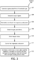
- FIG. 3 illustrates a method 300 for delivering high frequency positive pressure ventilation to a subject with a high frequency positive pressure ventilation system.
- the system comprises an inspiratory subsystem, an expiratory flow generator, one or more sensors, an exhalation valve, and one or more processors, and/or other components.
- the one or more processors are configured to execute computer program modules.
- the computer program modules comprise a parameter module, a target module, and a control module.
- Method 300 may be implemented in one or more processing devices (e.g., a digital processor, an analog processor, a digital circuit designed to process information, an analog circuit designed to process information, a state machine, and/or other mechanisms for electronically processing information).
- the one or more processing devices may include one or more devices executing some or all of the operations of method 300 in response to instructions stored electronically on an electronic storage medium.
- the one or more processing devices may include one or more devices configured through hardware, firmware, and/or software to be specifically designed for execution of one or more of the operations of method 300.
- a pressurized flow of breathable gas for delivery to the airway of the subject is generated with the inspiratory subsystem similar to inspiratory subsystem 14 (shown in FIG. 1 and described herein).
- Operation 302 may be performed at least in part by a expiratory flow generator and/or an exhalation valve the same as or similar to expiratory flow generator 34 and/or exhalation valve 36, respectively (shown in FIG. 1 and described herein).
- output signals conveying information related to one or more gas parameters of the pressurized flow of breathable gas are generated with the one or more sensors. Operation 304 may be performed by one or more sensors the same as or similar to sensors 40 (shown in FIG. 1 and described herein).
- the airway pressure of the subject is selectively controlled with the inspiratory subsystem, the expiratory flow generator and/or the one or more valves. Operation 306 may be performed at least in part by a inspiratory subsystem, an expiratory flow generator and/or an exhalation valve the same as or similar to inspiratory subsystem 14, expiratory flow generator 34 and/or exhalation valve 36, respectively (shown in FIG. 1 and described herein).
- the one or more gas parameters of the pressurized flow of breathable gas at or near the airway of the subject are determined based on the output signals with the parameter module.
- the one or more gas parameters may include a time averaged airway pressure level.
- the one or more gas parameters may include a peak-to-peak pressure difference. Operation 308 may be performed by a processor module the same as or similar to parameter module 42 (shown in FIG. 1 and described herein).
- target values for the one or more gas parameters are obtained with the target module.
- the target values may include a target time averaged airway pressure level.
- the one or more gas parameters may include a target peak-to-peak pressure difference. Operation 310 may be performed by a processor module the same as or similar to target module 44 (shown in FIG. 1 and described herein).
- the inspiratory subsystem, the expiratory flow generator and/or the exhalation valve may be controlled with the control module to generate the pressurized flow of breathable gas in accordance with a high frequency positive pressure ventilation therapy regime.
- Operation 312 may be performed by a processor module the same as or similar to control module 46 (shown in FIG. 1 and described herein).
- the inspiratory subsystem, the expiratory flow generator and/or the exhalation valve may be selectively controlled with the control module to maintain the time averaged airway pressure level at the target time averaged airway pressure level over a series of positive and negative pressures.
- the inspiratory subsystem, the expiratory flow generator and/or the exhalation valve may be selectively controlled with the control module to maintain the peak-to-peak pressure difference at the target peak-to-peak pressure difference over a series of pressure cycles.
- the time averaged airway pressure level and the peak-to-peak pressure difference may be maintained at their respective target levels at the same phases of the pressure cycles.
- Operation 314 may be performed by a processor module the same as or similar to control module 46 (shown in FIG. 1 and described herein).
Description
- The present disclosure pertains to a high frequency positive pressure ventilation system. The system may be configured to maintain a time averaged airway pressure level at a target time averaged airway pressure level and/or a peak-to-peak pressure difference at a target peak-to-peak pressure difference.
- High frequency ventilators are known. High frequency ventilators are used for delivery of low tidal volumes of breathable gas. High frequency oscillatory ventilation (HFOV) is a widely used type high frequency ventilation that uses a piston based system for generating positive and negative pressure oscillations. In addition to manually selecting the frequency of the high frequency ventilation, a user typically manually selects a peak-to-peak pressure and a mean airway pressure. The peak-to-peak pressure and the mean airway pressure determine a delivered tidal volume and an oxygenation of a patient's lungs. In high frequency oscillatory ventilation, peak-to-peak pressure is controlled by piston settings and the mean airway pressure is controlled by a balloon valve in the expiratory limb. The user manually adjusts the settings of this valve as the conditions in the patient's lungs change.
- Document
WO 2012/085792 A2 relates to a ventilator system including an integrated blower. In one case, the ventilator system includes: an inspiration port for connection to an inspiratory limb of a dual-limb patient circuit, and an expiration port for connection to an expiratory limb of the dual-limb patient circuit; a gas delivery device connected to the inspiration port to supply a pressurized flow of gas to the inspiration port to generate a positive pressure; and a blower having an inlet that is operatively connected to the expiration port and configured to be controlled to selectively supply a negative pressure level between 4 and 120 cmH2O to the expiration port, and an outlet to exhaust gas received from the expiration port. In another case, the ventilator system described therein includes a blower to generate positive pressure/flow to augment flow for noninvasive ventilation. - The present invention is defined by the appended claim.
-
-
FIG. 1 is a schematic illustration of a high frequency positive pressure ventilation system; -
FIG. 2 is a schematic illustration of a portion of a high frequency positive pressure ventilation system; -
FIG. 3 is a method for delivering high frequency positive pressure ventilation to a subject with a high frequency positive pressure ventilation system, which is not part of the present invention. - As used herein, the singular form of "a", "an", and "the" include plural references unless the context clearly dictates otherwise. As used herein, the statement that two or more parts or components are "coupled" shall mean that the parts are joined or operate together either directly or indirectly, i.e., through one or more intermediate parts or components, so long as a link occurs. As used herein, "directly coupled" means that two elements are directly in contact with each other. As used herein, "fixedly coupled" or "fixed" means that two components are coupled so as to move as one while maintaining a constant orientation relative to each other.
- As used herein, the word "unitary" means a component is created as a single piece or unit. That is, a component that includes pieces that are created separately and then coupled together as a unit is not a "unitary" component or body. As employed herein, the statement that two or more parts or components "engage" one another shall mean that the parts exert a force against one another either directly or through one or more intermediate parts or components. As employed herein, the term "number" shall mean one or an integer greater than one (i.e., a plurality).
- Directional phrases used herein, such as, for example and without limitation, top, bottom, left, right, upper, lower, front, back, and derivatives thereof, relate to the orientation of the elements shown in the drawings and are not limiting upon the claims unless expressly recited therein.
-
FIG. 1 schematically illustrates a high frequency positivepressure ventilation system 10. In some embodiments,system 10 comprises one or more of aventilator 12 that includes aninspiratory subsystem 14, anexpiratory subsystem 16, arespiratory circuit 18, aprocessor 20, electronic storage (not shown), and/or other components. In some embodiments,system 10 is configured to provide asubject 22 with ventilation in accordance with a high frequency positive pressure ventilation therapy regime.System 10 is configured to maintain a time averaged airway pressure level (e.g., mean airway pressure) and/or a peak-to-peak pressure level at target levels over a series of inhalations and/or exhalations.System 10 is configured to automatically maintain the time averaged airway pressure level and/or the peak-to-peak pressure level, reducing and/or eliminating the need for manual adjustments during high frequency positive pressure ventilation. Automatic control provides timely parameter adjustments as lung and respiratory conditions change during treatment. -
Respiratory circuit 18 is configured to deliver a pressurized flow of breathable gas to the airway of the subject in order to ventilatesubject 22.Respiratory circuit 18 includes one or more of aninspiratory conduit 24, anexpiratory circuit 26, asubject interface 28, and/or other components.Inspiratory conduit 24 is configured to deliver gas for inspiration frominspiratory subsystem 14 tosubject interface 28. Expiratory conduit is configured to communicate expired gas toexpiratory subsystem 16 fromsubject interface 28.Conduits 24 and/or 26 may be flexible, and/or may be selectively removable fromsubject interface 28,inspiratory subsystem 14, and/orexpiratory subsystem 16.Subject interface 28 includes asubject interface appliance 30 that communicates with the airway ofsubject 22.Subject interface appliance 30 may include an invasive appliance, such as an endotracheal tube or other invasive appliance, or a non-invasive appliance, such as a mask or other non-invasive appliance. -
Inspiratory subsystem 14 is configured to provide a pressurized flow of breathable gas for delivery to the airway ofsubject 22 during inspiration.Inspiratory subsystem 14 is configured such that one or more gas parameters of the pressurized flow of breathable gas are controlled in accordance with a therapy regime. The one or more gas parameters may include, for example, one or more of flow, pressure, humidity, velocity, acceleration, and/or other parameters. In some embodiments,system 10 is a device dedicated to high frequency positive pressure ventilation. In some embodiments,Inspiratory subsystem 14 is a ventilator and/or positive airway pressure device configured to provide therapy other than and/or in addition to high frequency positive pressure ventilation.Inspiratory subsystem 14 may include any device, such as, for example, a pump, compressed gas source, blower, piston, or bellows, that is capable of providing a flow of gas at an elevated pressure. The present disclosure also contemplates that gas other than ambient atmospheric air (e.g., oxygen enriched gas, medicament, and/or other gases) may be introduced intosystem 10 for delivery tosubject 22. -
Expiratory subsystem 16 is configured to exhaust gas from the airway ofsubject 22 and/orrespiratory circuit 18 to effect expiration of gas.Expiratory subsystem 16 may include one or more of anoutlet 32, anexpiratory flow generator 34, anexhalation valve 36, and/or other components.Outlet 32 is configured to release expired gas fromsystem 10. This may include releasing gas directly into ambient atmosphere, or releasing gas into a filter or other treatment component to treat the gas prior to release. Theexpiratory flow generator 34 is configured to draw gas throughexpiration conduit 26 and outoutlet 32. Theexpiratory flow generator 34 may include, for example, a blower, a bellows, and/or other devices or mechanisms suitable for generating a flow of gas fromexpiration conduit 26 out throughoutlet 32. The rate at whichexpiratory flow generator 34 creates the flow may be adjustable by adjusting the operation ofexpiratory flow generator 34. For example, a rotary speed of a blower may be adjusted to draw more or less gas out throughoutlet 32. -
Exhalation valve 36 is configured to selectively placeexpiratory conduit 26 in communication withexpiratory flow generator 34. In a first position (shown inFIG. 1 ),exhalation valve 36 may inhibit or completely shut off communication betweenexpiratory conduit 26 andexpiratory flow generator 34. At the first position, pressure in the airway ofsubject 22 will tend to rise as gas frominspiratory subsystem 14 is delivered tosubject 22 while little or no gas is permitted to be exhausted throughexpiratory subsystem 14.FIG. 2 illustratesexhalation valve 36 in a second position in whichexpiratory conduit 26 communicates withexpiratory flow generator 34 throughexhalation valve 36. This may cause pressure in the airway ofsubject 22 to fall, as gas from the airway ofsubject 22 is drawn out throughexpiratory conduit 26 andoutlet 32. - Returning to
FIG. 1 , whenexhalation valve 36 is in the first position shown inFIG. 1 , andexpiratory flow generator 34 is running to push a flow out throughoutlet 32, aleak port 38 may act as an inlet through which gas is drawn intoexpiratory flow generator 34.Leak port 38 may simply be a passive port (e.g., an opening, a flapper valve, and/or other passive ports), or may be actively opened asexhalation valve 36 is closed, and vice versa. In some embodiments,exhalation valve 36 is not merely opened and closed, but may be opened and closed incrementally to allow relatively more or less gas to flow fromexpiratory conduit 26 tooutlet 32. - It will be appreciated from the foregoing, that by controlling
exhalation valve 36 and/orexpiratory flow generator 34, pressure at the airway of subject 22 can be controlled while gas is delivered to the airway of subject 22 frominspiratory subsystem 14. The parameters (e.g., pressure, flow, etc.) of the gas delivered frominspiratory subsystem 14 may be controlled dynamically in coordination withexhalation valve 36 and/orexpiratory flow generator 34 to control airway pressure, or the inspiratory gas may be delivered substantially continuously and airway pressure controlled entirely or substantially entirely by adjusting operation ofexhalation valve 36 and/orexpiratory flow generator 34. - By way of a non-limiting example,
expiratory flow generator 34 and/orexhalation valve 36 may be configured to adjust the airway pressure in accordance with a high frequency ventilation regime. In some embodiments, the therapy regime may dictate that the airway pressure fluctuates over a series of pressure cycles in which a mean airway pressure is maintained. During these pressure cycles, the parameters such as frequency, pressure or flow amplitude, mean pressure, tidal volume, peak flow, and/or other parameters can be controlled through operation ofexpiratory flow generator 34 and/orexhalation valve 36. -
System 10 may include one ormore sensors 40 configured to generate output signals conveying information related to one or more gas parameters of the gas withinsystem 10. The one or more gas parameters may comprise flow, volume, pressure, a composition (e.g., concentration(s) of one or more constituents), temperature, humidity, acceleration, velocity, acoustics, changes in a parameter indicative of respiration, and/or other gas parameters.Sensors 40 may comprise one or more sensors that measure such parameters directly.Sensors 40 may comprise one or more sensors that generate output signals related to one or more parameters of the flow of gas indirectly. For example, one or more ofsensors 40 may generate an output based on an operating parameter of expiratory flow generator 34 (e.g., motor current, voltage, rotational velocity, and/or other operating parameters), and/or other parameters. Althoughsensors 40 are illustrated at a single location withinrespiratory circuit 18, this is not intended to be limiting.Sensors 40 may include sensors disposed in a plurality of locations, such as for example, withinexpiratory flow generator 34, within (or in communication with)inspiratory subsystem 14, and/or other locations. -
Processor 20 is configured to provide information processing capabilities insystem 10. As such,processor 20 may comprise one or more of a digital processor, an analog processor, a digital circuit designed to process information, an analog circuit designed to process information, a state machine, and/or other mechanisms for electronically processing information. Althoughprocessor 20 is shown inFIG. 1 as a single entity, this is for illustrative purposes only. In some implementations,processor 20 may comprise a plurality of processing units. These processing units may be physically located within the same device, orprocessor 20 may represent processing functionality of a plurality of devices operating in coordination. - As shown in
FIG. 1 ,processor 20 is configured to execute one or more computer program modules. The one or more computer program modules may comprise one or more of a parameter module 42, a target module 44, acontrol module 46, and/or other modules.Processor 20 may be configured to execute modules 42, 44, and/or 46 by software; hardware; firmware; some combination of software, hardware, and/or firmware; and/or other mechanisms for configuring processing capabilities onprocessor 24. - It should be appreciated that although modules 42, 44, and/or 46 are illustrated in
FIG. 1 as being co-located within a single processing unit, in implementations in whichprocessor 20 comprises multiple processing units, one or more of modules 42, 44, and/or 46 may be located remotely from the other modules. The description of the functionality provided by the different modules 42, 44, and/or 46 described below is for illustrative purposes, and is not intended to be limiting, as any of modules 42, 44, and/or 46 may provide more or less functionality than is described. For example, one or more of modules 42, 44, and/or 46 may be eliminated, and some or all of its functionality may be provided by other modules 42, 44, and/or 46. As another example,processor 20 may be configured to execute one or more additional modules that may perform some or all of the functionality attributed below to one of modules 42, 44, and/or 46. - Parameter module 42 is configured to determine one or more parameters within
system 10. The one or more parameters withinsystem 10 may comprise gas parameters related to the flow of breathable gas at or near the airway of subject 22, and/or other parameters. Parameter module 42 is configured to determine the one or more parameters based on the output signals ofsensors 40, and/or other information. The information determined by parameter module 42 may be used for controllingexpiratory flow generator 34, controllingexhalation valve 36, stored in electronic storage, and/or used for other uses. The one or more gas parameters of the pressurized flow of breathable gas may comprise, for example, one or more of a flow rate, a volume, a pressure, humidity, temperature, acceleration, velocity, and/or other gas parameters. - In some embodiments, parameter module 42 may be configured to determine the respiratory phase (e.g., inhalation, exhalation) and/or or high frequency pressure cycles during ventilation of
subject 12. The respiratory phase may include the phase of the determinations made by parameter module 25 are based on the output signals from pressure cycles generated through control ofinspriatory subsystem 14,expiratory flow generator 34 and/orexhalation valve 36. Parameter module 42 may be configured to determine additional respiratory parameters related to the respiration ofsubject 22. Additional respiratory parameters related to the respiration of subject 22 may comprise a tidal volume, a timing (e.g., beginning and/or end of inhalation, beginning and/or end of exhalation, etc.), a respiration rate, a duration (e.g., of inhalation, of exhalation, of a single breathing cycle, etc.), respiration frequency, the frequency of high frequency pressure cycles, mean airway pressure and/or other respiratory parameters. The respiratory phase determinations may be used bycontrol module 46 to controlexpiratory flow generator 34 and/orexhalation valve 36 to control the airway pressure of subject 22, may be stored in electronic storage, and/or used for other uses. In some embodiments, parameter module 42 is configured to determine the respiratory phase (e.g., inhalation, exhalation) based on changes in pressure, flow rate, and/or other parameters determined by parameter module 42. - Parameter module 42 may be configured to determine a time averaged airway pressure level. The time averaged airway pressure level may be the mean airway pressure, for example. In some embodiments, the time averaged airway pressure level may be averaged continuously during a therapy session. A current time averaged airway pressure level may be determined based on a previously determined time averaged airway pressure level and the current output signals from
sensors 40. In some embodiments, the time averaged airway pressure level may be determined during a therapy window. For example, the time averaged airway pressure level may be averaged over a therapy window of the two (or more) most recent high frequency ventilation cycles. In some embodiments the averaged may be over a predetermined amount of time just prior to the current high frequency ventilation cycle. - Parameter module 42 may be configured to determine a peak-to-peak pressure difference based on the output signals. In some embodiments, the peak-to-peak pressure difference may be related to differences between two or more consecutive maximum pressures in a cyclic pressure wave generated by the operation of
inspiratory subsystem 14,expiratory flow generator 34 and/orexhalation valve 36 according to the high frequency positive pressure ventilation therapy regime. In some embodiments, the peak-to-peak pressure difference may be determined continuously during a therapy session. A current peak-to-peak pressure difference may be determined based on a previously determined peak pressure level and a current peak pressure level indicated by the output signals fromsensors 40. - In some embodiments, a frequency of the determinations, algorithms used to determine the parameters, and/or other factors related to determination of the gas parameters by parameter module 25 may be determined at manufacture, determined based on user input via a user interface, determined based on previous and/or current respiration by the subject, determined based on the therapy regime, and/or determined in other ways.
- Target module 44 is configured to obtain target values for the one or more gas parameters. Target module 44 is configured to obtain a target time averaged airway pressure level. In some embodiments, the target time averaged airway pressure level may be a mean airway pressure level. Target module 44 is configured to obtain a target peak-to-peak pressure difference. In some embodiments, target module 44 is configured to determine the target values for the gas parameters based on previous respiration of the subject. In some embodiments, the target values for the gas parameters may be determined at manufacture. In some embodiments, target module 44 may obtain the target values for the gas parameters based on information entered by the subject and/or other users (e.g., a caregiver, a doctor) via a user interface. In some embodiments, target module 27 may obtain the target values via other methods.
-
I Control module 46 is configured to controlinspiratory subsystem 14,expiratory flow generator 34 and/orexhalation valve 36 to provide an airway pressure in accordance with a high frequency positive pressure ventilation therapy regime.Control module 46 is configured to control theinspiratory subsystem 14, theexpiratory flow generator 34 and/orexhalation valve 36 in accordance with the high frequency positive pressure ventilation therapy regime based on the output signals fromsensors 40.Control module 46 is configured to controlinspiratory subsystem 14,expiratory flow generator 34 and/or exhalation valve to cause airway pressure cycles at a frequency between about 3Hz and about 25Hz.Control module 46 is configured to controlinspiratory subsystem 14,expiratory flow generator 34 and/orexhalation valve 36 such that a tidal volume of the pressurized flow of breathable gas is about 6 ml/kg for a patient. - In some embodiments,
control module 46 is configured to selectively controlinspiratory subsystem 14,expiratory flow generator 34 and/orexhalation valve 36 to maintain the time averaged airway pressure level at the target time averaged airway pressure level over a number of pressure cycles. The individual cycles may correspond to an inhalation and exhalation by the subject. In some embodiments, the time averaged airway pressure level may be the mean airway pressure.Control module 46 is configured to selectivelyinspiratory subsystem 14,expiratory flow generator 34 and/orexhalation valve 36 to maintain the time averaged airway pressure level at the target time averaged airway pressure level based on the output signals, the information determined by parameter module 42, the information obtained by target module 44, and/or other information. - By way of a non-limiting example, an airway pressure may be determined and averaged over few high frequency positive pressure cycles by parameter module 42. The number of pressure cycles for which the pressure is averaged may depend on the frequency of the high frequency ventilation. The difference (or error for example) between a target mean airway pressure (obtained by target module 44) and a current mean airway pressure may be determined by
control module 46. Based on the determined difference,control module 46 may simultaneously 1) control an extent to whichexhalation valve 36 is opened and/or closed, increase and/or decrease the current/speed of a blower ofexpiratory flow generator 34, and/or control other aspects of the operation ofsystem 10 to impact airway pressure. If, for example, the current mean airway pressure is higher than the target mean airway pressure,control module 46 may control the blower speed to increase such that negative pressure is increased during expiration. In addition,control module 46 may controlexhalation valve 36 to open partially to facilitate faster changes to the negative pressure during exhalation. - In some embodiments,
control module 46 is configured to selectively controlexpiratory flow generator 34 and/orexhalation valve 36 to maintain the peak-to-peak pressure difference at the target peak-to-peak pressure difference over the pressure cycles.Control module 46 is configured to selectively controlexpiratory flow generator 34 and/orexhalation valve 36 to maintain the peak-to-peak pressure difference at the target peak-to-peak pressure difference based on the output signals, the information determined by parameter module 42, the information obtained by target module 44, and/or other information. In some embodiments,control module 46 may be configured to compare a current peak-to-peak pressure difference to the target peak-to-peak pressure difference expiratory flowgenerator 34, theexhalation valve 36, and/or other components ofsystem 10 based on the comparison. Control module 29 may be configured to controlvalve 18,valve 20, and/orinspiratory flow generator 14 substantially simultaneously to maintain the peak-to-peak pressure at the target peak-to-peak pressure. - In some embodiments,
control module 46 is configured to maintain the time averaged airway pressure level at the target time averaged airway pressure level, and the peak-to-peak pressure difference at the target peak-to-peak pressure difference, during the same series of pressures cycles. - In some embodiments,
control module 46 is configured to controlinspiratory subsystem 14,expiratory flow generator 34,exhalation valve 36, and/or other devices to generate the flow of gas in accordance with a ventilator regime, a positive airway pressure therapy regime, and/or other therapy regimes in addition to and/or instead of the high frequency positive pressure support therapy regime. -
FIG. 3 illustrates amethod 300 for delivering high frequency positive pressure ventilation to a subject with a high frequency positive pressure ventilation system. The system comprises an inspiratory subsystem, an expiratory flow generator, one or more sensors, an exhalation valve, and one or more processors, and/or other components. The one or more processors are configured to execute computer program modules. The computer program modules comprise a parameter module, a target module, and a control module. The operations ofmethod 300 presented below are intended to be illustrative.Method 300 may be accomplished with one or more additional operations not described, and/or without one or more of the operations discussed. Additionally, the order in which the operations ofmethod 300 are illustrated inFIG. 3 and described below is not intended to be limiting. -
Method 300 may be implemented in one or more processing devices (e.g., a digital processor, an analog processor, a digital circuit designed to process information, an analog circuit designed to process information, a state machine, and/or other mechanisms for electronically processing information). The one or more processing devices may include one or more devices executing some or all of the operations ofmethod 300 in response to instructions stored electronically on an electronic storage medium. The one or more processing devices may include one or more devices configured through hardware, firmware, and/or software to be specifically designed for execution of one or more of the operations ofmethod 300. - At an
operation 302, a pressurized flow of breathable gas for delivery to the airway of the subject is generated with the inspiratory subsystem similar to inspiratory subsystem 14 (shown inFIG. 1 and described herein).Operation 302 may be performed at least in part by a expiratory flow generator and/or an exhalation valve the same as or similar toexpiratory flow generator 34 and/orexhalation valve 36, respectively (shown inFIG. 1 and described herein). - At an
operation 304, output signals conveying information related to one or more gas parameters of the pressurized flow of breathable gas are generated with the one or more sensors.Operation 304 may be performed by one or more sensors the same as or similar to sensors 40 (shown inFIG. 1 and described herein). - At an
operation 306, the airway pressure of the subject is selectively controlled with the inspiratory subsystem, the expiratory flow generator and/or the one or more valves.Operation 306 may be performed at least in part by a inspiratory subsystem, an expiratory flow generator and/or an exhalation valve the same as or similar toinspiratory subsystem 14,expiratory flow generator 34 and/orexhalation valve 36, respectively (shown inFIG. 1 and described herein). - At an
operation 308, the one or more gas parameters of the pressurized flow of breathable gas at or near the airway of the subject are determined based on the output signals with the parameter module. The one or more gas parameters may include a time averaged airway pressure level. The one or more gas parameters may include a peak-to-peak pressure difference.Operation 308 may be performed by a processor module the same as or similar to parameter module 42 (shown inFIG. 1 and described herein). - At an
operation 310, target values for the one or more gas parameters are obtained with the target module. The target values may include a target time averaged airway pressure level. The one or more gas parameters may include a target peak-to-peak pressure difference.Operation 310 may be performed by a processor module the same as or similar to target module 44 (shown inFIG. 1 and described herein). - At an
operation 312, the inspiratory subsystem, the expiratory flow generator and/or the exhalation valve may be controlled with the control module to generate the pressurized flow of breathable gas in accordance with a high frequency positive pressure ventilation therapy regime.Operation 312 may be performed by a processor module the same as or similar to control module 46 (shown inFIG. 1 and described herein). - At an operation 314, the inspiratory subsystem, the expiratory flow generator and/or the exhalation valve may be selectively controlled with the control module to maintain the time averaged airway pressure level at the target time averaged airway pressure level over a series of positive and negative pressures. The inspiratory subsystem, the expiratory flow generator and/or the exhalation valve may be selectively controlled with the control module to maintain the peak-to-peak pressure difference at the target peak-to-peak pressure difference over a series of pressure cycles. The time averaged airway pressure level and the peak-to-peak pressure difference may be maintained at their respective target levels at the same phases of the pressure cycles. Operation 314 may be performed by a processor module the same as or similar to control module 46 (shown in
FIG. 1 and described herein).
Claims (1)
- A high frequency positive pressure ventilation system (10), the system comprising:an inspiratory subsystem (14) to generate a pressurized flow of breathable gas for delivery to the airway of the subject;an expiratory flow generator (34) configured to draw gas from the airway of a subject to a system outlet;one or more sensors (40) configured to generate output signals conveying information related to one or more gas parameters at or near the airway of the subject;an exhalation valve (36) configured to selectively control flow from the airway of the subject though the expiratory flow generator;one or more processors (24) configured to execute computer program modules, the computer program modules comprising:a parameter module (42) configured to determine a peak-to-peak pressure difference over a series of high frequency pressure cycles based on the output signals, and to determine a time averaged airway pressure level;a target module (44) configured to obtain a target peak-to-peak pressure difference, and to obtain a target time averaged airway pressure level; anda control module (46) configured to control the inspiratory subsystem, the expiratory flow generator and the exhalation valve to maintain the time averaged airway pressure level at the target time averaged airway pressure level over the series of high frequency pressure cycles, and to selectively control the inspiratory subsystem, the expiratory flow generator and the exhalation valve to maintain the peak-to-peak pressure difference at the target peak-to-peak pressure difference over the series of high frequency pressure cycles; wherein the parameter module is configured such that the peak-to-peak pressure difference is related to a difference between two or more consecutive maximum pressures.
Applications Claiming Priority (2)
| Application Number | Priority Date | Filing Date | Title |
|---|---|---|---|
| US201361753554P | 2013-01-17 | 2013-01-17 | |
| PCT/IB2014/058141 WO2014111832A1 (en) | 2013-01-17 | 2014-01-09 | System and method for controlling airway gas parameters during high frequency positive pressure ventilation |
Publications (2)
| Publication Number | Publication Date |
|---|---|
| EP2945677A1 EP2945677A1 (en) | 2015-11-25 |
| EP2945677B1 true EP2945677B1 (en) | 2020-07-15 |
Family
ID=50023813
Family Applications (1)
| Application Number | Title | Priority Date | Filing Date |
|---|---|---|---|
| EP14701626.5A Active EP2945677B1 (en) | 2013-01-17 | 2014-01-09 | System for controlling airway gas parameters during high frequency positive pressure ventilation |
Country Status (7)
| Country | Link |
|---|---|
| US (1) | US10252012B2 (en) |
| EP (1) | EP2945677B1 (en) |
| JP (1) | JP6378205B2 (en) |
| CN (1) | CN104936644B (en) |
| BR (1) | BR112015016799B1 (en) |
| RU (1) | RU2656528C2 (en) |
| WO (1) | WO2014111832A1 (en) |
Families Citing this family (11)
| Publication number | Priority date | Publication date | Assignee | Title |
|---|---|---|---|---|
| JP2019505355A (en) * | 2016-02-22 | 2019-02-28 | トリヴィクラムTrivikram | Respiratory management device |
| US11129906B1 (en) | 2016-12-07 | 2021-09-28 | David Gordon Bermudes | Chimeric protein toxins for expression by therapeutic bacteria |
| DE102017009606A1 (en) * | 2017-10-13 | 2019-06-19 | Drägerwerk AG & Co. KGaA | Method and device for high-frequency ventilation of a patient |
| CN110464951B (en) * | 2019-08-29 | 2022-04-08 | 宁波戴维医疗器械股份有限公司 | High-frequency respirator system and ventilation control method |
| CN110464950B (en) * | 2019-08-29 | 2022-01-25 | 宁波戴维医疗器械股份有限公司 | High-frequency respirator system and ventilation control method |
| CN110464946B (en) * | 2019-08-29 | 2022-07-12 | 宁波戴维医疗器械股份有限公司 | High-frequency respirator system and control method |
| EP4119176A4 (en) * | 2020-03-11 | 2023-04-26 | Shenzhen Mindray Bio-Medical Electronics Co., Ltd | Respiratory ventilation system and method |
| WO2021217223A1 (en) * | 2020-04-28 | 2021-11-04 | Omnitek Tecnologia Ltda. | Ventilator with one-way valve |
| WO2021232268A1 (en) * | 2020-05-20 | 2021-11-25 | 深圳迈瑞生物医疗电子股份有限公司 | Medical ventilation device, control method, and storage medium |
| CN114377258B (en) * | 2021-12-21 | 2023-09-19 | 北京谊安医疗系统股份有限公司 | Control device and control method for basic flow of neonate breathing machine |
| CN116357604A (en) * | 2023-04-11 | 2023-06-30 | 沃杰(北京)科技有限公司 | High-performance turbine fan control method, system and medium |
Citations (2)
| Publication number | Priority date | Publication date | Assignee | Title |
|---|---|---|---|---|
| WO2007142642A1 (en) * | 2006-06-07 | 2007-12-13 | Viasys Manufacturing, Inc. | System and method for adaptive high frequency flow interrupter control in a patient respiratory ventilator |
| WO2012085792A2 (en) * | 2010-12-21 | 2012-06-28 | Koninklijke Philips Electronics N.V. | Ventilator with integrated blower to provide negative or positive pressure in a ventilator system |
Family Cites Families (9)
| Publication number | Priority date | Publication date | Assignee | Title |
|---|---|---|---|---|
| SU1538915A1 (en) * | 1985-08-21 | 1990-01-30 | Ташкентский Филиал Всесоюзного Научного Центра Хирургии Амн Ссср | Device for high-frequency artificial pulmonary ventilation |
| US5165398A (en) * | 1989-12-08 | 1992-11-24 | Bird F M | Ventilator and oscillator for use therewith and method |
| US5166398A (en) * | 1991-06-21 | 1992-11-24 | Warner-Lambert Co. | 4-oxy-substituted phenoxyalkyl carboxylic acid, ester, and alcohol derivatives as antihyper-cholesterolemic and antiatherosclerotic agents |
| JP3721912B2 (en) | 2000-01-11 | 2005-11-30 | スズキ株式会社 | High frequency ventilator |
| US6390092B1 (en) * | 2000-08-07 | 2002-05-21 | Sensormedics Corporation | Device and method for using oscillatory pressure ratio as an indicator for lung opening during high frequency oscillatory ventilation |
| DE102009012146B4 (en) * | 2009-03-06 | 2017-08-24 | Drägerwerk AG & Co. KGaA | Method for operating a ventilator |
| FR2953853B1 (en) * | 2009-12-15 | 2013-02-08 | Total Raffinage Marketing | BIODEGRADABLE LUBRICATING COMPOSITION AND ITS USE IN A DRILLING FLUID, IN PARTICULAR FOR VERY BURIED TANKS |
| US10058664B2 (en) * | 2009-12-15 | 2018-08-28 | Koninklijke Philips N.V. | System and method for supporting sub-physiologic and physiologic tidal volumes in spontaneous or non-spontaneous breathing during high frequency ventilation |
| US20130220324A1 (en) * | 2012-02-29 | 2013-08-29 | Nellcor Puritan Bennett Llc | Systems and methods for providing oscillatory pressure control ventilation |
-
2014
- 2014-01-09 RU RU2015134350A patent/RU2656528C2/en active
- 2014-01-09 CN CN201480005049.4A patent/CN104936644B/en active Active
- 2014-01-09 JP JP2015553201A patent/JP6378205B2/en active Active
- 2014-01-09 WO PCT/IB2014/058141 patent/WO2014111832A1/en active Application Filing
- 2014-01-09 BR BR112015016799-3A patent/BR112015016799B1/en active IP Right Grant
- 2014-01-09 US US14/655,767 patent/US10252012B2/en active Active
- 2014-01-09 EP EP14701626.5A patent/EP2945677B1/en active Active
Patent Citations (2)
| Publication number | Priority date | Publication date | Assignee | Title |
|---|---|---|---|---|
| WO2007142642A1 (en) * | 2006-06-07 | 2007-12-13 | Viasys Manufacturing, Inc. | System and method for adaptive high frequency flow interrupter control in a patient respiratory ventilator |
| WO2012085792A2 (en) * | 2010-12-21 | 2012-06-28 | Koninklijke Philips Electronics N.V. | Ventilator with integrated blower to provide negative or positive pressure in a ventilator system |
Also Published As
| Publication number | Publication date |
|---|---|
| JP6378205B2 (en) | 2018-08-22 |
| CN104936644A (en) | 2015-09-23 |
| US20150335840A1 (en) | 2015-11-26 |
| EP2945677A1 (en) | 2015-11-25 |
| BR112015016799A2 (en) | 2017-07-11 |
| BR112015016799B1 (en) | 2022-02-08 |
| RU2015134350A (en) | 2017-02-22 |
| JP2016503705A (en) | 2016-02-08 |
| CN104936644B (en) | 2018-08-07 |
| RU2656528C2 (en) | 2018-06-05 |
| WO2014111832A1 (en) | 2014-07-24 |
| US10252012B2 (en) | 2019-04-09 |
Similar Documents
| Publication | Publication Date | Title |
|---|---|---|
| EP2945677B1 (en) | System for controlling airway gas parameters during high frequency positive pressure ventilation | |
| EP3113822B1 (en) | Blending gas enriched pressure support system | |
| US10166360B2 (en) | System and method for controlling flow during exhalation in a respiratory support system | |
| JP6223340B2 (en) | Method and apparatus for controlling a ventilator device | |
| AU2013365956B2 (en) | Inspiratory pressure control in volume mode ventilation cross-reference to related applications | |
| US10500356B2 (en) | System and method for controlling insufflation pressure during inexsufflation | |
| EP2603266B1 (en) | System for providing a pressurized flow of breathable gas to the airway of a subject with stochastic fluctuations | |
| EP2852424A1 (en) | System and method for pressure support therapy with shaped airflow | |
| JP2015502212A (en) | System and method for using partial CO2 rebreathing integrated in a ventilator and its measurement to determine non-invasive cardiac output | |
| EP2938379B1 (en) | System for limiting flow compensation during limited flow respiratory therapy | |
| EP2846861B1 (en) | Systems to determine the fraction of inhaled oxygen during ventilation. | |
| CN112704789A (en) | High-frequency oscillation respiratory airflow generation method and respiratory support equipment | |
| US10881821B2 (en) | Mechanical ventilation based on alveolar ventilation | |
| EP2688620B1 (en) | Systems to manage central sleep apnea by controlling accumulated retrograde volume | |
| US20210213234A1 (en) | High flow oxygen therapy with on-demand humidification and an active exhalation valve |
Legal Events
| Date | Code | Title | Description |
|---|---|---|---|
| PUAI | Public reference made under article 153(3) epc to a published international application that has entered the european phase |
Free format text: ORIGINAL CODE: 0009012 |
|
| 17P | Request for examination filed |
Effective date: 20150817 |
|
| AK | Designated contracting states |
Kind code of ref document: A1 Designated state(s): AL AT BE BG CH CY CZ DE DK EE ES FI FR GB GR HR HU IE IS IT LI LT LU LV MC MK MT NL NO PL PT RO RS SE SI SK SM TR |
|
| AX | Request for extension of the european patent |
Extension state: BA ME |
|
| DAX | Request for extension of the european patent (deleted) | ||
| STAA | Information on the status of an ep patent application or granted ep patent |
Free format text: STATUS: EXAMINATION IS IN PROGRESS |
|
| 17Q | First examination report despatched |
Effective date: 20180307 |
|
| REG | Reference to a national code |
Ref country code: DE Ref legal event code: R079 Ref document number: 602014067693 Country of ref document: DE Free format text: PREVIOUS MAIN CLASS: A61M0016000000 Ipc: A61M0016200000 |
|
| GRAP | Despatch of communication of intention to grant a patent |
Free format text: ORIGINAL CODE: EPIDOSNIGR1 |
|
| STAA | Information on the status of an ep patent application or granted ep patent |
Free format text: STATUS: GRANT OF PATENT IS INTENDED |
|
| RIC1 | Information provided on ipc code assigned before grant |
Ipc: A61M 16/20 20060101AFI20200124BHEP |
|
| INTG | Intention to grant announced |
Effective date: 20200212 |
|
| RIN1 | Information on inventor provided before grant (corrected) |
Inventor name: GARDE, SMITA Inventor name: AHMAD, SAMIR |
|
| RAP1 | Party data changed (applicant data changed or rights of an application transferred) |
Owner name: KONINKLIJKE PHILIPS N.V. |
|
| GRAS | Grant fee paid |
Free format text: ORIGINAL CODE: EPIDOSNIGR3 |
|
| GRAA | (expected) grant |
Free format text: ORIGINAL CODE: 0009210 |
|
| STAA | Information on the status of an ep patent application or granted ep patent |
Free format text: STATUS: THE PATENT HAS BEEN GRANTED |
|
| AK | Designated contracting states |
Kind code of ref document: B1 Designated state(s): AL AT BE BG CH CY CZ DE DK EE ES FI FR GB GR HR HU IE IS IT LI LT LU LV MC MK MT NL NO PL PT RO RS SE SI SK SM TR |
|
| REG | Reference to a national code |
Ref country code: GB Ref legal event code: FG4D Ref country code: CH Ref legal event code: EP |
|
| REG | Reference to a national code |
Ref country code: DE Ref legal event code: R096 Ref document number: 602014067693 Country of ref document: DE |
|
| REG | Reference to a national code |
Ref country code: IE Ref legal event code: FG4D |
|
| REG | Reference to a national code |
Ref country code: AT Ref legal event code: REF Ref document number: 1290295 Country of ref document: AT Kind code of ref document: T Effective date: 20200815 |
|
| REG | Reference to a national code |
Ref country code: LT Ref legal event code: MG4D |
|
| REG | Reference to a national code |
Ref country code: AT Ref legal event code: MK05 Ref document number: 1290295 Country of ref document: AT Kind code of ref document: T Effective date: 20200715 |
|
| REG | Reference to a national code |
Ref country code: NL Ref legal event code: MP Effective date: 20200715 |
|
| PG25 | Lapsed in a contracting state [announced via postgrant information from national office to epo] |
Ref country code: HR Free format text: LAPSE BECAUSE OF FAILURE TO SUBMIT A TRANSLATION OF THE DESCRIPTION OR TO PAY THE FEE WITHIN THE PRESCRIBED TIME-LIMIT Effective date: 20200715 Ref country code: ES Free format text: LAPSE BECAUSE OF FAILURE TO SUBMIT A TRANSLATION OF THE DESCRIPTION OR TO PAY THE FEE WITHIN THE PRESCRIBED TIME-LIMIT Effective date: 20200715 Ref country code: BG Free format text: LAPSE BECAUSE OF FAILURE TO SUBMIT A TRANSLATION OF THE DESCRIPTION OR TO PAY THE FEE WITHIN THE PRESCRIBED TIME-LIMIT Effective date: 20201015 Ref country code: PT Free format text: LAPSE BECAUSE OF FAILURE TO SUBMIT A TRANSLATION OF THE DESCRIPTION OR TO PAY THE FEE WITHIN THE PRESCRIBED TIME-LIMIT Effective date: 20201116 Ref country code: SE Free format text: LAPSE BECAUSE OF FAILURE TO SUBMIT A TRANSLATION OF THE DESCRIPTION OR TO PAY THE FEE WITHIN THE PRESCRIBED TIME-LIMIT Effective date: 20200715 Ref country code: LT Free format text: LAPSE BECAUSE OF FAILURE TO SUBMIT A TRANSLATION OF THE DESCRIPTION OR TO PAY THE FEE WITHIN THE PRESCRIBED TIME-LIMIT Effective date: 20200715 Ref country code: AT Free format text: LAPSE BECAUSE OF FAILURE TO SUBMIT A TRANSLATION OF THE DESCRIPTION OR TO PAY THE FEE WITHIN THE PRESCRIBED TIME-LIMIT Effective date: 20200715 Ref country code: FI Free format text: LAPSE BECAUSE OF FAILURE TO SUBMIT A TRANSLATION OF THE DESCRIPTION OR TO PAY THE FEE WITHIN THE PRESCRIBED TIME-LIMIT Effective date: 20200715 Ref country code: GR Free format text: LAPSE BECAUSE OF FAILURE TO SUBMIT A TRANSLATION OF THE DESCRIPTION OR TO PAY THE FEE WITHIN THE PRESCRIBED TIME-LIMIT Effective date: 20201016 Ref country code: NO Free format text: LAPSE BECAUSE OF FAILURE TO SUBMIT A TRANSLATION OF THE DESCRIPTION OR TO PAY THE FEE WITHIN THE PRESCRIBED TIME-LIMIT Effective date: 20201015 |
|
| PG25 | Lapsed in a contracting state [announced via postgrant information from national office to epo] |
Ref country code: IS Free format text: LAPSE BECAUSE OF FAILURE TO SUBMIT A TRANSLATION OF THE DESCRIPTION OR TO PAY THE FEE WITHIN THE PRESCRIBED TIME-LIMIT Effective date: 20201115 Ref country code: PL Free format text: LAPSE BECAUSE OF FAILURE TO SUBMIT A TRANSLATION OF THE DESCRIPTION OR TO PAY THE FEE WITHIN THE PRESCRIBED TIME-LIMIT Effective date: 20200715 Ref country code: RS Free format text: LAPSE BECAUSE OF FAILURE TO SUBMIT A TRANSLATION OF THE DESCRIPTION OR TO PAY THE FEE WITHIN THE PRESCRIBED TIME-LIMIT Effective date: 20200715 Ref country code: LV Free format text: LAPSE BECAUSE OF FAILURE TO SUBMIT A TRANSLATION OF THE DESCRIPTION OR TO PAY THE FEE WITHIN THE PRESCRIBED TIME-LIMIT Effective date: 20200715 |
|
| PG25 | Lapsed in a contracting state [announced via postgrant information from national office to epo] |
Ref country code: NL Free format text: LAPSE BECAUSE OF FAILURE TO SUBMIT A TRANSLATION OF THE DESCRIPTION OR TO PAY THE FEE WITHIN THE PRESCRIBED TIME-LIMIT Effective date: 20200715 |
|
| REG | Reference to a national code |
Ref country code: DE Ref legal event code: R097 Ref document number: 602014067693 Country of ref document: DE |
|
| PG25 | Lapsed in a contracting state [announced via postgrant information from national office to epo] |
Ref country code: SM Free format text: LAPSE BECAUSE OF FAILURE TO SUBMIT A TRANSLATION OF THE DESCRIPTION OR TO PAY THE FEE WITHIN THE PRESCRIBED TIME-LIMIT Effective date: 20200715 Ref country code: RO Free format text: LAPSE BECAUSE OF FAILURE TO SUBMIT A TRANSLATION OF THE DESCRIPTION OR TO PAY THE FEE WITHIN THE PRESCRIBED TIME-LIMIT Effective date: 20200715 Ref country code: CZ Free format text: LAPSE BECAUSE OF FAILURE TO SUBMIT A TRANSLATION OF THE DESCRIPTION OR TO PAY THE FEE WITHIN THE PRESCRIBED TIME-LIMIT Effective date: 20200715 Ref country code: EE Free format text: LAPSE BECAUSE OF FAILURE TO SUBMIT A TRANSLATION OF THE DESCRIPTION OR TO PAY THE FEE WITHIN THE PRESCRIBED TIME-LIMIT Effective date: 20200715 Ref country code: DK Free format text: LAPSE BECAUSE OF FAILURE TO SUBMIT A TRANSLATION OF THE DESCRIPTION OR TO PAY THE FEE WITHIN THE PRESCRIBED TIME-LIMIT Effective date: 20200715 Ref country code: IT Free format text: LAPSE BECAUSE OF FAILURE TO SUBMIT A TRANSLATION OF THE DESCRIPTION OR TO PAY THE FEE WITHIN THE PRESCRIBED TIME-LIMIT Effective date: 20200715 |
|
| PLBE | No opposition filed within time limit |
Free format text: ORIGINAL CODE: 0009261 |
|
| STAA | Information on the status of an ep patent application or granted ep patent |
Free format text: STATUS: NO OPPOSITION FILED WITHIN TIME LIMIT |
|
| PG25 | Lapsed in a contracting state [announced via postgrant information from national office to epo] |
Ref country code: AL Free format text: LAPSE BECAUSE OF FAILURE TO SUBMIT A TRANSLATION OF THE DESCRIPTION OR TO PAY THE FEE WITHIN THE PRESCRIBED TIME-LIMIT Effective date: 20200715 |
|
| 26N | No opposition filed |
Effective date: 20210416 |
|
| PG25 | Lapsed in a contracting state [announced via postgrant information from national office to epo] |
Ref country code: SK Free format text: LAPSE BECAUSE OF FAILURE TO SUBMIT A TRANSLATION OF THE DESCRIPTION OR TO PAY THE FEE WITHIN THE PRESCRIBED TIME-LIMIT Effective date: 20200715 |
|
| PG25 | Lapsed in a contracting state [announced via postgrant information from national office to epo] |
Ref country code: MC Free format text: LAPSE BECAUSE OF FAILURE TO SUBMIT A TRANSLATION OF THE DESCRIPTION OR TO PAY THE FEE WITHIN THE PRESCRIBED TIME-LIMIT Effective date: 20200715 Ref country code: SI Free format text: LAPSE BECAUSE OF FAILURE TO SUBMIT A TRANSLATION OF THE DESCRIPTION OR TO PAY THE FEE WITHIN THE PRESCRIBED TIME-LIMIT Effective date: 20200715 |
|
| REG | Reference to a national code |
Ref country code: CH Ref legal event code: PL |
|
| PG25 | Lapsed in a contracting state [announced via postgrant information from national office to epo] |
Ref country code: LU Free format text: LAPSE BECAUSE OF NON-PAYMENT OF DUE FEES Effective date: 20210109 |
|
| REG | Reference to a national code |
Ref country code: BE Ref legal event code: MM Effective date: 20210131 |
|
| PG25 | Lapsed in a contracting state [announced via postgrant information from national office to epo] |
Ref country code: CH Free format text: LAPSE BECAUSE OF NON-PAYMENT OF DUE FEES Effective date: 20210131 Ref country code: LI Free format text: LAPSE BECAUSE OF NON-PAYMENT OF DUE FEES Effective date: 20210131 |
|
| PG25 | Lapsed in a contracting state [announced via postgrant information from national office to epo] |
Ref country code: IE Free format text: LAPSE BECAUSE OF NON-PAYMENT OF DUE FEES Effective date: 20210109 |
|
| PG25 | Lapsed in a contracting state [announced via postgrant information from national office to epo] |
Ref country code: BE Free format text: LAPSE BECAUSE OF NON-PAYMENT OF DUE FEES Effective date: 20210131 |
|
| PGFP | Annual fee paid to national office [announced via postgrant information from national office to epo] |
Ref country code: FR Payment date: 20230124 Year of fee payment: 10 |
|
| PG25 | Lapsed in a contracting state [announced via postgrant information from national office to epo] |
Ref country code: HU Free format text: LAPSE BECAUSE OF FAILURE TO SUBMIT A TRANSLATION OF THE DESCRIPTION OR TO PAY THE FEE WITHIN THE PRESCRIBED TIME-LIMIT; INVALID AB INITIO Effective date: 20140109 |
|
| PGFP | Annual fee paid to national office [announced via postgrant information from national office to epo] |
Ref country code: GB Payment date: 20230124 Year of fee payment: 10 Ref country code: DE Payment date: 20220628 Year of fee payment: 10 |
|
| PG25 | Lapsed in a contracting state [announced via postgrant information from national office to epo] |
Ref country code: CY Free format text: LAPSE BECAUSE OF FAILURE TO SUBMIT A TRANSLATION OF THE DESCRIPTION OR TO PAY THE FEE WITHIN THE PRESCRIBED TIME-LIMIT Effective date: 20200715 |