EP3209357B1 - System for controlling leak - Google Patents
System for controlling leak Download PDFInfo
- Publication number
- EP3209357B1 EP3209357B1 EP15781756.0A EP15781756A EP3209357B1 EP 3209357 B1 EP3209357 B1 EP 3209357B1 EP 15781756 A EP15781756 A EP 15781756A EP 3209357 B1 EP3209357 B1 EP 3209357B1
- Authority
- EP
- European Patent Office
- Prior art keywords
- sleeve
- dial
- leak
- orifices
- tubular body
- Prior art date
- Legal status (The legal status is an assumption and is not a legal conclusion. Google has not performed a legal analysis and makes no representation as to the accuracy of the status listed.)
- Active
Links
- 230000037361 pathway Effects 0.000 claims description 34
- 238000002644 respiratory therapy Methods 0.000 claims description 18
- 230000008878 coupling Effects 0.000 claims description 14
- 238000010168 coupling process Methods 0.000 claims description 14
- 238000005859 coupling reaction Methods 0.000 claims description 14
- 239000007789 gas Substances 0.000 description 54
- 238000000034 method Methods 0.000 description 17
- CURLTUGMZLYLDI-UHFFFAOYSA-N Carbon dioxide Chemical compound O=C=O CURLTUGMZLYLDI-UHFFFAOYSA-N 0.000 description 12
- 230000029058 respiratory gaseous exchange Effects 0.000 description 12
- 238000012545 processing Methods 0.000 description 11
- 238000002560 therapeutic procedure Methods 0.000 description 10
- 229910002092 carbon dioxide Inorganic materials 0.000 description 9
- 239000001569 carbon dioxide Substances 0.000 description 9
- 238000004891 communication Methods 0.000 description 6
- 230000003434 inspiratory effect Effects 0.000 description 5
- 230000036387 respiratory rate Effects 0.000 description 5
- 238000009423 ventilation Methods 0.000 description 5
- 230000008569 process Effects 0.000 description 4
- 230000007246 mechanism Effects 0.000 description 3
- 230000001133 acceleration Effects 0.000 description 2
- 230000008859 change Effects 0.000 description 2
- 238000004590 computer program Methods 0.000 description 2
- 239000012530 fluid Substances 0.000 description 2
- 230000000241 respiratory effect Effects 0.000 description 2
- 229930091051 Arenine Natural products 0.000 description 1
- 208000035967 Long Term Adverse Effects Diseases 0.000 description 1
- 208000008784 apnea Diseases 0.000 description 1
- QVGXLLKOCUKJST-UHFFFAOYSA-N atomic oxygen Chemical compound [O] QVGXLLKOCUKJST-UHFFFAOYSA-N 0.000 description 1
- 239000000470 constituent Substances 0.000 description 1
- 230000001419 dependent effect Effects 0.000 description 1
- 239000003814 drug Substances 0.000 description 1
- 230000003028 elevating effect Effects 0.000 description 1
- 230000010365 information processing Effects 0.000 description 1
- 210000004072 lung Anatomy 0.000 description 1
- 238000004519 manufacturing process Methods 0.000 description 1
- 238000005259 measurement Methods 0.000 description 1
- 238000012986 modification Methods 0.000 description 1
- 230000004048 modification Effects 0.000 description 1
- 210000002445 nipple Anatomy 0.000 description 1
- 230000003287 optical effect Effects 0.000 description 1
- 229910052760 oxygen Inorganic materials 0.000 description 1
- 239000001301 oxygen Substances 0.000 description 1
- 231100000572 poisoning Toxicity 0.000 description 1
- 230000000607 poisoning effect Effects 0.000 description 1
- 230000004044 response Effects 0.000 description 1
- 230000001953 sensory effect Effects 0.000 description 1
- 230000001225 therapeutic effect Effects 0.000 description 1
- 230000000007 visual effect Effects 0.000 description 1
Images


Classifications
-
- A—HUMAN NECESSITIES
- A61—MEDICAL OR VETERINARY SCIENCE; HYGIENE
- A61M—DEVICES FOR INTRODUCING MEDIA INTO, OR ONTO, THE BODY; DEVICES FOR TRANSDUCING BODY MEDIA OR FOR TAKING MEDIA FROM THE BODY; DEVICES FOR PRODUCING OR ENDING SLEEP OR STUPOR
- A61M16/00—Devices for influencing the respiratory system of patients by gas treatment, e.g. mouth-to-mouth respiration; Tracheal tubes
- A61M16/20—Valves specially adapted to medical respiratory devices
- A61M16/201—Controlled valves
- A61M16/202—Controlled valves electrically actuated
- A61M16/203—Proportional
- A61M16/205—Proportional used for exhalation control
-
- A—HUMAN NECESSITIES
- A61—MEDICAL OR VETERINARY SCIENCE; HYGIENE
- A61M—DEVICES FOR INTRODUCING MEDIA INTO, OR ONTO, THE BODY; DEVICES FOR TRANSDUCING BODY MEDIA OR FOR TAKING MEDIA FROM THE BODY; DEVICES FOR PRODUCING OR ENDING SLEEP OR STUPOR
- A61M16/00—Devices for influencing the respiratory system of patients by gas treatment, e.g. mouth-to-mouth respiration; Tracheal tubes
- A61M16/021—Devices for influencing the respiratory system of patients by gas treatment, e.g. mouth-to-mouth respiration; Tracheal tubes operated by electrical means
- A61M16/022—Control means therefor
- A61M16/024—Control means therefor including calculation means, e.g. using a processor
-
- A—HUMAN NECESSITIES
- A61—MEDICAL OR VETERINARY SCIENCE; HYGIENE
- A61M—DEVICES FOR INTRODUCING MEDIA INTO, OR ONTO, THE BODY; DEVICES FOR TRANSDUCING BODY MEDIA OR FOR TAKING MEDIA FROM THE BODY; DEVICES FOR PRODUCING OR ENDING SLEEP OR STUPOR
- A61M16/00—Devices for influencing the respiratory system of patients by gas treatment, e.g. mouth-to-mouth respiration; Tracheal tubes
- A61M16/20—Valves specially adapted to medical respiratory devices
- A61M16/201—Controlled valves
-
- F—MECHANICAL ENGINEERING; LIGHTING; HEATING; WEAPONS; BLASTING
- F16—ENGINEERING ELEMENTS AND UNITS; GENERAL MEASURES FOR PRODUCING AND MAINTAINING EFFECTIVE FUNCTIONING OF MACHINES OR INSTALLATIONS; THERMAL INSULATION IN GENERAL
- F16K—VALVES; TAPS; COCKS; ACTUATING-FLOATS; DEVICES FOR VENTING OR AERATING
- F16K11/00—Multiple-way valves, e.g. mixing valves; Pipe fittings incorporating such valves
- F16K11/02—Multiple-way valves, e.g. mixing valves; Pipe fittings incorporating such valves with all movable sealing faces moving as one unit
- F16K11/06—Multiple-way valves, e.g. mixing valves; Pipe fittings incorporating such valves with all movable sealing faces moving as one unit comprising only sliding valves, i.e. sliding closure elements
- F16K11/065—Multiple-way valves, e.g. mixing valves; Pipe fittings incorporating such valves with all movable sealing faces moving as one unit comprising only sliding valves, i.e. sliding closure elements with linearly sliding closure members
- F16K11/07—Multiple-way valves, e.g. mixing valves; Pipe fittings incorporating such valves with all movable sealing faces moving as one unit comprising only sliding valves, i.e. sliding closure elements with linearly sliding closure members with cylindrical slides
- F16K11/0716—Multiple-way valves, e.g. mixing valves; Pipe fittings incorporating such valves with all movable sealing faces moving as one unit comprising only sliding valves, i.e. sliding closure elements with linearly sliding closure members with cylindrical slides with fluid passages through the valve member
-
- F—MECHANICAL ENGINEERING; LIGHTING; HEATING; WEAPONS; BLASTING
- F16—ENGINEERING ELEMENTS AND UNITS; GENERAL MEASURES FOR PRODUCING AND MAINTAINING EFFECTIVE FUNCTIONING OF MACHINES OR INSTALLATIONS; THERMAL INSULATION IN GENERAL
- F16K—VALVES; TAPS; COCKS; ACTUATING-FLOATS; DEVICES FOR VENTING OR AERATING
- F16K31/00—Actuating devices; Operating means; Releasing devices
- F16K31/44—Mechanical actuating means
- F16K31/50—Mechanical actuating means with screw-spindle or internally threaded actuating means
- F16K31/504—Mechanical actuating means with screw-spindle or internally threaded actuating means the actuating means being rotable, rising, and having internal threads which co-operate with threads on the outside of the valve body
-
- F—MECHANICAL ENGINEERING; LIGHTING; HEATING; WEAPONS; BLASTING
- F16—ENGINEERING ELEMENTS AND UNITS; GENERAL MEASURES FOR PRODUCING AND MAINTAINING EFFECTIVE FUNCTIONING OF MACHINES OR INSTALLATIONS; THERMAL INSULATION IN GENERAL
- F16K—VALVES; TAPS; COCKS; ACTUATING-FLOATS; DEVICES FOR VENTING OR AERATING
- F16K37/00—Special means in or on valves or other cut-off apparatus for indicating or recording operation thereof, or for enabling an alarm to be given
- F16K37/0008—Mechanical means
- F16K37/0016—Mechanical means having a graduated scale
-
- A—HUMAN NECESSITIES
- A61—MEDICAL OR VETERINARY SCIENCE; HYGIENE
- A61M—DEVICES FOR INTRODUCING MEDIA INTO, OR ONTO, THE BODY; DEVICES FOR TRANSDUCING BODY MEDIA OR FOR TAKING MEDIA FROM THE BODY; DEVICES FOR PRODUCING OR ENDING SLEEP OR STUPOR
- A61M2205/00—General characteristics of the apparatus
- A61M2205/15—Detection of leaks
-
- A—HUMAN NECESSITIES
- A61—MEDICAL OR VETERINARY SCIENCE; HYGIENE
- A61M—DEVICES FOR INTRODUCING MEDIA INTO, OR ONTO, THE BODY; DEVICES FOR TRANSDUCING BODY MEDIA OR FOR TAKING MEDIA FROM THE BODY; DEVICES FOR PRODUCING OR ENDING SLEEP OR STUPOR
- A61M2205/00—General characteristics of the apparatus
- A61M2205/33—Controlling, regulating or measuring
- A61M2205/3331—Pressure; Flow
- A61M2205/3337—Controlling, regulating pressure or flow by means of a valve by-passing a pump
-
- A—HUMAN NECESSITIES
- A61—MEDICAL OR VETERINARY SCIENCE; HYGIENE
- A61M—DEVICES FOR INTRODUCING MEDIA INTO, OR ONTO, THE BODY; DEVICES FOR TRANSDUCING BODY MEDIA OR FOR TAKING MEDIA FROM THE BODY; DEVICES FOR PRODUCING OR ENDING SLEEP OR STUPOR
- A61M2205/00—General characteristics of the apparatus
- A61M2205/50—General characteristics of the apparatus with microprocessors or computers
Definitions
- the present disclosure pertains to a system for controlling leak during respiratory therapy.
- the inspiration of expired gases enriched with CO 2 is called rebreathing, which has short and long term adverse effects on a subject including CO 2 poisoning.
- Leak valves configured to exhaust these expired gases are known. Typically these valves allow a predetermined amount of leak at a given pressure and are not adjustable.
- the valve comprises a tubular body, a sleeve, a dial, and/or other components.
- the tubular body is formed along a first axis of the valve.
- the tubular body has a first end, a second end, and a wall.
- the tubular body forms a flow path configured to conduct gas between the first end and the second end during respiratory therapy.
- the tubular body has body orifices formed in the wall that communicate gas from the flow path through the wall.
- the sleeve is rotatable about the first axis with respect to the tubular body. The sleeve substantially surrounds the body orifices in the body.
- the sleeve has sleeve orifices formed therein.
- the sleeve orifices are formed in the sleeve and are positionable to overlap with the body orifices.
- the dial has a tubular shape.
- the dial is rotatable about the first axis relative to the sleeve.
- the dial substantially surrounds the sleeve orifices in the sleeve.
- the dial has a dial orifice formed therein.
- the dial orifice is formed in the dial and positionable to overlap with the sleeve orifices and the body orifices.
- Rotational coupling between the tubular body, the sleeve, and the dial facilitates adjustable configuration of one or more properties of a leak pathway formed by positioning the overlapping of the dial orifice with at least one of the sleeve orifices and at least one of the body orifices to allow leak during respiratory therapy.
- US6581596 , WO2013/144740 and US2014/174444 disclose an adjustable leak valve configured to control leak during respiratory therapy according to the preamble of claim 1.
- the word "unitary” means a component is created as a single piece or unit. That is, a component that includes pieces that are created separately and then coupled together as a unit is not a “unitary” component or body.
- the statement that two or more parts or components "engage” one another shall mean that the parts exert a force against one another either directly or through one or more intermediate parts or components.
- the term “number” shall mean one or an integer greater than one (i.e., a plurality).
- FIG. 1 illustrates a system 10 for controlling a leak flow rate during respiratory therapy.
- System 10 includes a single limb ventilation circuit (though other circuits are contemplated). Leak in a single limb device is necessary to expel exhaled carbon dioxide (CO 2 ).
- System 10 is configured to determine a leak flow rate necessary for CO 2 expulsion for an individual subject 12 and facilitate control of the leak flow rate during therapy (e.g., so the leak flow rate is not excessively low or excessively high for subject 12) such that system 10 exhausts substantially the entire exhaled volume of gas during an expiration of subject 12.
- System 10 facilitates control of the leak flow rate during therapy via an adjustable leak valve 50.
- system 10 comprises one or more of pressure generator 14, a subject interface 16, a sensor 18, a processor 20, a user interface 22, electronic storage 24, and leak valve 50.
- Pressure generator 14 is configured to generate a pressurized flow of breathable gas for delivery to the airway of subject 12. Pressure generator 14 may control one or more parameters of the flow of gas (e.g., flow rate, pressure, volume, temperature, duration, a timing, gas composition, etc.) for therapeutic purposes, and/or for other purposes. Pressure generator 14 receives a flow of gas from a gas source, such as the ambient atmosphere, and elevates and/or reduces the pressure of that gas for delivery to the airway of a patient. Pressure generator 14 is any device, such as, for example, a pump, blower, piston, or bellows, that is capable of elevating and/or reducing the pressure of the received gas for delivery to a patient.
- a gas source such as the ambient atmosphere
- Pressure generator 14 may comprise one or more valves for controlling the pressure and/or flow of gas, for example.
- the present disclosure also contemplates controlling the operating speed of the blower, either alone or in combination with such valves, to control the pressure and/or flow of gas provided to the patient.
- Sensors 18 are configured to generate output signals conveying information related to one or more gas parameters of the pressurized flow of breathable gas, one or more breathing parameters related to the respiration of subject 12, and/or other information.
- the one or more gas parameters and/or the one or more breathing parameters may comprise one or more of a flow rate, a volume, a pressure, a composition (e.g., concentration(s) of one or more constituents), temperature, humidity, acceleration, velocity, acoustic parameters, parameters indicative of respiratory effort by subject 12, a timing, a duration, a frequency, and/or other parameters.
- Sensors 18 may comprise one or more sensors that measure such parameters directly (e.g., through fluid communication with the flow of gas in subject interface 16).
- Sensors 18 may comprise one or more sensors that generate output signals related to one or more parameters of the flow of gas indirectly. For example, one or more of sensors 18 may generate an output based on an operating parameter of pressure generator 14 (e.g., a valve driver or motor current, voltage, rotational velocity, and/or other operating parameters). Although sensors 18 are illustrated at a single location within (or in communication with) conduit 30 between interface appliance 32 and pressure generator 14, this is not intended to be limiting. Sensors 18 may include sensors disposed in a plurality of locations, such as for example, within pressure generator 14, within (or in communication with) interface appliance 32, in communication with subject 12, and/or in other locations.
- an operating parameter of pressure generator 14 e.g., a valve driver or motor current, voltage, rotational velocity, and/or other operating parameters.
- Subject interface 16 is configured to deliver the pressurized flow of breathable gas to the airway of subject 12.
- subject interface 16 comprises a conduit 30, an interface appliance 32, and/or other components.
- Conduit 30 is configured to convey the pressurized flow of gas to interface appliance 32.
- Conduit 30 may be a flexible length of hose, or other conduit, that places interface appliance 32 in fluid communication with pressure generator 14.
- Interface appliance 32 is configured to deliver the flow of gas to the airway of subject 12.
- interface appliance 32 is non-invasive. As such, interface appliance 32 non-invasively engages subject 12.
- Non-invasive engagement comprises removably engaging an area (or areas) surrounding one or more external orifices of the airway of subject 12 (e.g., nostrils and/or mouth) to communicate gas between the airway of subject 12 and interface appliance 32.
- Some examples of non-invasive interface appliance 32 may comprise, for example, a nasal cannula, a nasal mask, a nasal/oral mask, a full face mask, a total face mask, or other interface appliances that communicate a flow of gas with an airway of a subject.
- the present disclosure is not limited to these examples, and contemplates delivery of the flow of gas to the subject using any interface appliance, including an invasive interface appliance such as an endotracheal tube and/or other appliances.
- Leak valve 50 is configured to control leak during respiratory therapy.
- An assembled view of valve 50 is illustrated in FIG. 2 .
- FIG. 3 illustrates an exploded view of leak valve 50.
- leak valve 50 includes a tubular body 52, a sleeve 66, a dial 70, and/or other components.
- Tubular body 52 is formed along a first axis 54 of valve 50.
- Tubular body 52 is generally tube shaped and has a length 80 along first axis 54 of about 5 inches. In some embodiments, length 80 may be between about 3 inches and about 7 inches.
- Tubular body 52 has a diameter 81 of about 0.8 inches. In some embodiments, diameter 81 may be between about 0.5 inches and about 1.5 inches.
- Tubular body 52 has a first end 56, a second end 58 ( FIG. 3 ), a wall 60, and/or other components.
- Tubular body 52 forms a flow path 62 configured to conduct gas between first end 56 and second end 58 during respiratory therapy.
- Tubular body 52 has body orifices 64 ( FIG. 3 ) formed in wall 60 that communicate gas from flow path 62 through wall 60.
- Body orifices 64 are generally rectangular in shape, with a length 82 ( FIG. 3 ) running along first axis 54 of about 0.7 inches and a width 84 ( FIG. 3 ) running along a circumference of tubular body 52 of about 0.2 inches.
- length 82 may be between about 0.5 and about 0.9 inches and width 84 may be between about 0.1 and about 0.3 inches.
- the shapes and sizes of tubular body 52 and/or features of tubular body 52 (e.g., body orifices 64) illustrated in FIG. 2 and FIG. 3 and described above are not intended to be limiting.
- Tubular body 52 and/or features of tubular body 52 may have any shape and/or size that allows tubular body 52 to function as described herein.
- tubular body 52 includes features 86 ( FIG. 3 ) configured to facilitate coupling (e.g., rotatable and/or other coupling) with sleeve 66 and/or other components.
- features 86 include threads and/or other features.
- Features 86 may be located in one or more locations on tubular body 52. For example, as illustrated in FIG. 3 , features 86 are located in a first location 88 toward first end 56 and a second location 90 toward second end 58.
- Sleeve 66 is rotatably coupled (e.g., rotatable) about first axis 54 with tubular body 52 along first axis 54 such that sleeve 66 substantially surrounds body orifices 64 in tubular body 52.
- Sleeve 66 is generally cylindrically shaped and has a length 200 ( FIG. 3 ) along first axis 54 of about 2.5 inches and a diameter 202 of about 0.95 inches. In some embodiments length 200 is between about 2 inches and about 3 inches. In some embodiments, diameter 202 is between about 0.5 inches and about 1.5 inches.
- Sleeve 66 has a first end 204 ( FIG. 3 ), a second end 206, a wall 208, and/or other components.
- Sleeve 66 has sleeve orifices 68 ( FIG.
- Sleeve orifices 68 are formed in sleeve 66 to overlap along first axis 54 with body orifices 64. Sleeve orifices 68 are positionable to overlap with the body orifices.
- Sleeve orifices 68 are generally rectangular in shape, with a length 212 ( FIG. 3 ) running along first axis 54 and a width running along a circumference of sleeve 66.
- individual sleeve orifices 68 have different cross-sectional areas that correspond to individual positive end expiratory pressures (PEEP). In some embodiments, there are nine (this is not intended to be limiting) individual sleeve orifices 68.
- sleeve 66 and/or features of sleeve 66 are not intended to be limiting.
- Sleeve 66 and/or features of sleeve 66 may have any shape and/or size, in any quantity, that allows sleeve 66 to function as described herein.
- sleeve 66 includes features 214 ( FIG. 3 ) configured to facilitate coupling (e.g., rotatable and/or other coupling) with tubular body 52, dial 70, and/or other components of valve 50.
- features 214 include threads (e.g., on an inside surface of sleeve 66 that correspond to the threads on tubular body 52), detents (e.g., that correspond to individual ones of sleeve orifices 68 and/or features in dial 70) and/or other features.
- Features 214 may be located in one or more locations on sleeve 66. For example, as illustrated in FIG. 3 , detent features 214 are located toward second end 206 along first axis 54 relative to sleeve orifices 68.
- Dial 70 is generally tube shaped and has a length 300 along first axis 54 of about 1.38 inches and a diameter 302 of about 1.41 inches. In some embodiments, length 300 and/or diameter 302 may be between about 1 inch and about 2 inches. Dial 70 is rotatably coupled about first axis 54 with sleeve 66 along first axis 54 such that dial 70 substantially surrounds sleeve orifices 68 in sleeve 66. Dial 70 has a dial orifice 72 formed therein. Dial orifice 72 is formed in dial 70 to overlap along first axis 54 with sleeve orifices 68 and body orifices 64.
- Dial orifice is positionable to overlap with sleeve orifices 68 and/or body orifices 64, and/or other components of valve 50.
- Dial orifice 72 is generally rectangular in shape, with a length 312 ( FIG. 3 ) of about 0.7 inches running along first axis 54 and a width 314 of about 0.15 inches running along a circumference of sleeve 66.
- length 312 is between about 0.5 inches and about 1 inch.
- width 314 is between about 0.1 inches and about 0.2 inches.
- dial 70 includes features configured to facilitate coupling (e.g., rotatable and/or other coupling) with sleeve 66, and/or other components of valve 50.
- these features may include detent features (e.g., on an inside surface of dial 70 that correspond to the detent features on sleeve 66) and/or other features. These features may be located in one or more locations on sleeve dial 70.
- detent features e.g., on an inside surface of dial 70 that correspond to the detent features on sleeve 66
- these features may be located in one or more locations on sleeve dial 70.
- the shapes and sizes of dial 70 and/or features of dial 70 (e.g., dial orifice 72) illustrated in FIG. 2 and FIG. 3 and described above are not intended to be limiting. Dial 70 and/or features of dial 70 may have any shape and/or size that allows sleeve 66 to function as described herein.
- valve 50 may include one or more components 99 configured to facilitate coupling valve 50 with one or more components of subject interface 16 ( FIG. 1 ).
- components 99 may include a swivel, a nipple, a barb, a fastener, a pipe coupling, and/or other coupling components.
- Rotational coupling between tubular body 52, sleeve 66, and dial 70 facilitates adjustable configuration of one or more properties of a leak pathway formed by overlapping dial orifice 72 with one of the sleeve orifices 68 and one of the body orifices 64 to allow leak during respiratory therapy.
- tubular body 52, sleeve 66, and dial 70 are configured such that the one or more properties of the leak pathway include a cross-sectional area of the leak pathway.
- tubular body 52, sleeve 66, and dial 70 are configured such that the cross-sectional area of the leak pathway corresponds to one or more of a PEEP pressure, a leak flow rate, and/or other parameters.
- sleeve 66 may be threaded onto tubular body 52.
- Dial 70 may be slip fit over sleeve 66 and detented to sleeve 66 such that dial 70 may freely rotate (subject to the detents) about sleeve 66.
- a PEEP level indicator 350 may be fixedly coupled with sleeve 66 such that PEEP levels 352 indicated on PEEP level indicator 350 correspond to sleeve orifices 68 of different sizes, and such that dial 70 may still freely rotate on sleeve 66.
- Dial orifice 72 may be aligned with one of the PEEP level indicators 352 (e.g., a desired and/or prescribed PEEP level), which uncovers a corresponding one (and/or a portion of a corresponding one) of the sleeve orifices 68.
- PEEP level indicators 352 e.g., a desired and/or prescribed PEEP level
- sleeve 66 may be rotated on tubular body 52 such that aligned dial orifice 72 / sleeve orifice 68 uncover (and/or cover) one or more of the body orifices 64 (wholly and/or partially) to form a leak pathway that facilitates leak at a specific flow rate (e.g., corresponding to the cross-sectional area of the flow pathway).
- the specific leak flow rate may be indicated via a leak flow rate scale 375 marked on tubular body 52 and/or by other indicators.
- the specific leak flow rate may be indicated by the location of second end 206 of sleeve 66 on leak flow rate scale 375. In FIG. 2 , the leak flow rate indicated is 15 LPM, for example.
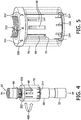
- FIG. 4 and FIG. 5 illustrate rotational 400 alignment of dial orifice 72 with one of the sleeve orifices 68.
- Dial orifice 72 may be rotated 400 ( FIG. 4 ) such that it becomes aligned with one of the PEEP level indicators 352 (e.g., a desired and/or prescribed PEEP level), which uncovers a corresponding one (and/or a portion of a corresponding one) of the sleeve orifices 68 ( FIG. 5 ).
- Dial 70 and dial orifice 72 are shown in FIG. 4 and FIG. 5 as wireframe outlines so that sleeve 66 and sleeve orifices 68 are visible for illustration.
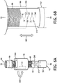
- FIG. 6A illustrates rotation 600 of sleeve 66 and dial 70 on tubular body 52.
- FIG. 6B illustrates travel 602 of sleeve 66 along first axis 54 on tubular body 52.
- sleeve 66 may be threaded (e.g., via features 86) onto tubular body 52. While the rotational alignment between dial orifice 72 and one of the sleeve orifices 68 (shown in FIG. 4 and FIG.
- sleeve 66 may be rotated on tubular body 52 such that aligned dial orifice 72 / sleeve orifice 68 uncover (and/or cover) one or more of the body orifices 64 (not shown) to form a leak pathway that facilitates leak at a specific flow rate (e.g., corresponding to the cross-sectional area of the flow pathway).
- Rotating sleeve 66 in one direction causes sleeve 66 to travel toward second end 206 along first axis 54 and rotating sleeve 66 in the opposite direction (e.g., counter clockwise) causes sleeve 66 to travel toward first end 204 (shown in FIG. 3 ) along first axis 54.
- the specific leak flow rate may be indicated via a leak flow rate scale 375 marked on tubular body 52 and/or by other indicators.
- the specific leak flow rate may be indicated by the location of second end 206 of sleeve 66 on leak flow rate scale 375. In FIG. 6B , the leak flow rate indicated is 15 LPM, for example.
- FIG. 7A and 7B illustrate flow path 100 formed by overlapping dial orifice 72 with one of the sleeve orifices 68 and one of the body orifices 64.
- Rotational coupling between tubular body 52, sleeve 66, and dial 70 facilitates adjustable configuration of one or more properties of leak pathway 100.
- the one or more properties of leak pathway 100 include a cross-sectional area of the leak pathway and/or other properties.
- tubular body 52, sleeve 66, and dial 70 are configured such that the cross-sectional area of the leak pathway corresponds to one or more of a PEEP pressure (e.g., as indicated by alignment of dial orifice 72 with PEEP levels 352 indicated on PEEP level indicator 350), a leak flow rate (e.g., as indicated by the position of second end 206 of sleeve 66 on leak flow rate scale 375), and/or other parameters.
- a PEEP pressure e.g., as indicated by alignment of dial orifice 72 with PEEP levels 352 indicated on PEEP level indicator 350
- a leak flow rate e.g., as indicated by the position of second end 206 of sleeve 66 on leak flow rate scale 375
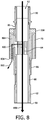
- FIG. 8 illustrates gas flow 800 through valve 50 during exhalation of subject 12 ( FIG. 1 ).
- Valve 50 is configured to exhaust substantially the entire exhaled volume of gas during an expiration of subject 12. Exhaled gas may flow through flow pathway 62.
- Leaked gas 802 flows through leak pathway 100 to the ambient environment.
- dial 70 is configured such that dial orifice 72 is formed on an inside surface of dial 70 and allows leaked gas to flow into an internal cavity 804 within a wall of dial 70 before flowing out to the ambient environment 806.
- the cross-sectional area of cavity 804 is larger than the cross section area of leak pathway 100 so as not to limit the flow rate of leaked gas through leak pathway 100.
- Leaked gas 802 flows into cavity 804 so that the exhausted leaked gas 802 is directed away from the subject (e.g., subject 12).
- processor 20 is configured to provide information processing capabilities in system 10.
- processor 20 may comprise one or more of a digital processor, an analog processor, or a digital circuit designed to process information, an analog circuit designed to process information, a state machine, and/or other mechanisms for electronically processing information.
- processor 20 is shown in FIG. 1 as a single entity, this is for illustrative purposes only.
- processor 20 may comprise a plurality of processing units. These processing units may be physically located within the same device (e.g., sensory pressure generator 14, user interface 22), or processor 20 may represent processing functionality of a plurality of devices operating in coordination.
- processor 20 is configured to execute one or more computer program components.
- the one or more computer program components may comprise one or more of a parameter component 42, a leak component 44, a control component 46, and/or other components.
- Processor 20 may be configured to execute components 42, 44, and/or 46 by software; hardware; firmware; some combination of software, hardware, and/or firmware; and/or other mechanisms for configuring processing capabilities on processor 20.
- components 42, 44, and 46 are illustrated in FIG. 1 as being co-located within a single processing unit, in embodiments in which processor 20 comprises multiple processing units, one or more of components 42, 44, and/or 46 may be located remotely from the other components.
- the description of the functionality provided by the different components 42, 44, and/or 46 described below is for illustrative purposes, and is not intended to be limiting, as any of components 42, 44, and/or 46 may provide more or less functionality than is described.
- processor 20 may be configured to execute one or more additional components that may perform some or all of the functionality attributed below to one of components 42, 44, and/or 46.
- Parameter component 42 is configured to determine one or more parameters within system 10.
- the one or more parameters within system 10 may comprise gas parameters related to the pressurized flow of breathable gas, breathing parameters related to the respiration of subject 12, and/or other parameters.
- Parameter component 42 is configured to determine the one or more parameters based on the output signals of sensors 18, and/or other information.
- the one or more gas parameters of the pressurized flow of breathable gas may comprise, for example, one or more of a flow rate, a volume (e.g., a tidal volume, a minute volume, etc.), a pressure, humidity, temperature, acceleration, velocity, and/or other gas parameters.
- the one or more gas parameters may include a minute volume.
- the minute volume may be the amount of expired gas (such as 10 liters per minute) that is enriched with CO2 and therefore relates to a specification for the leak flow rate to expel gas prior to the next inspiration to prevent rebreathing. It may be a measurement of the total volume of gas exiting the lungs per minute.
- the one or more breathing parameters may include, for example, a tidal volume, a composition, a timing (e.g., beginning and/or end of inhalation, beginning and/or end of exhalation, etc.), a duration (e.g., of inhalation, of exhalation, of a single breathing cycle, an inspiratory time, an expiratory time, a full breath time, etc.), a breath rate, a respiration frequency (e.g., a respiratory rate), a parameter indicative of respiratory effort, and/or other parameters.
- the information determined by parameter component 42 may be used for controlling pressure generator 14, stored in electronic storage 24, and/or used for other uses.
- Leak component 44 is configured to determine a cross-sectional area for the leak pathway 100 ( FIG. 7A and 7B ) formed by overlapping the dial orifice 72 ( FIG. 7A and 7B ) with one of the sleeve orifices 68 ( FIG. 7A and 7B ) and one of the body orifices 64 ( FIG. 7A and 7B ) for subject 12.
- Leak component 44 is configured to determine the cross-sectional area based on the output signals from sensors 18, the parameters determined by parameter component 42, information stored in electronic storage 24, information entered and/or received via user interface 22, and/or other information.
- leak component 44 is configured to determine a leak flow rate ( Q leak ) for subject 12 that substantially prevents rebreathing of exhaled CO 2 enriched gas, obtain a prescribed PEEP level for subject 12 (e.g., via entry and/or selection of the PEEP level via user interface 22 by subject 12, a doctor, a caregiver, and/or other users), and then determine the cross-sectional area for leak pathway 100 based on the determined leak flow rate, the prescribed PEEP, and/or other information.
- Q leak a leak flow rate for subject 12 that substantially prevents rebreathing of exhaled CO 2 enriched gas
- leak component 44 is configured to determine the leak flow rate ( Q leak ) for subject 12 that substantially prevents rebreathing as follows (where the various parameters listed in the individual equations below are determined by parameter component 42 as described above, for example).
- Parameter component 42 may be configured to monitor the volume of gas expired on individual breaths and determine average parameters - e.g., minute volume by itself is the average over one minute.
- the time permitted during the expiration may also be monitored and also be averaged, such that the leak parameter may be determined based on the averages with some safety margin in order to accommodate variations breath to breath.)
- Q leak Tidal Volume Expiratory Time
- Tidal Volume Minute Volume Respiratory Rate
- Equation (2) Minute Volume RespiratoryRate ⁇ ExpiratoryTime .
- MinVent EET is therefore the volume expired during only the expiratory time of a breath of subject 12, or equivalently, the average expiratory flow rate expressed in volume per minute.
- Leak component 44 is configured to determine Q leak (the leak flow rate) such that Q leak is high enough to expel substantially the entire volume expired by subject 12 during exhalation (the leak flow rate is greater than MinVent EET ).
- leak component 44 is configured to determine the cross-sectional area for leak pathway 100 based on the determined leak flow rate, the prescribed PEEP level, and/or other information.
- leak component 44 may determine the information in FIG. 9 .
- the information in FIG. 9 may be previously determined and/or stored in electronic storage 24 and accessed and/or obtained by leak component 44.
- Leak component 44 may determine the cross-sectional area for leak pathway 100 using the information in FIG. 9 and/or similar information along with the determined leak flow rate and the prescribed PEEP level.
- valve 50 may include one or more screens, filters, and/or other devices configured to filter, restrict, and/or otherwise change the relationship between flow and the area of the orifice to something other than Bernoulli's equation in the various components of valve 50.
- leak component 44 is configured to account for these and/or similar features when determining the cross-sectional area for leak pathway 100.
- leak component 44 may determine a Q leak of 24 liters per minute (LPM) based on the equations above and an orifice size of about .22cm 2 based on the information in FIG. 9 .
- LPM 24 liters per minute
- FIG. 9 tracking 950 from a PEEP level of 6 cm H2O across graph 901 until reaching expected leak flow rate 914 that corresponds to 24 LPM results 952 in an orifice size of about .22cm 2 .
- Control component 46 is configured to control pressure generator 14 to generate the flow of gas in accordance with a positive pressure support therapy regime.
- positive airway pressure support therapy the pressurized flow of gas generated by the pressure generator is controlled to replace and/or compliment a patient's regular breathing.
- Positive airway pressure support therapy may be used to maintain an open airway in a patient so that oxygen and carbon dioxide may be exchanged more easily, requiring little and/or no effort from the patient.
- control component 46 may control pressure generator 14 such that the pressure support provided to the subject via the flow of gas comprises continuous positive airway pressure support (CPAP), bi-level positive airway pressure support (BPAP), proportional positive airway pressure support (PPAP), ventilation therapy, and/or other types of pressure support therapy.
- CPAP continuous positive airway pressure support
- BPAP bi-level positive airway pressure support
- PPAP proportional positive airway pressure support
- ventilation therapy and/or other types of pressure support therapy.
- CPAP supplies a fixed positive pressure to maintain a continuous level of positive airway pressure in a patient.
- BPAP provides a first inspiratory pressure (IPAP) and a second, typically lower, expiratory pressure (EPAP) to promote or assist tidal ventilation.
- control component 46 may control pressure generator 14 to apply variable pressure support in which the amount of pressure delivered to the patient during inhalation and/or during exhalation is determined and delivered on a breath by breath basis.
- control component 46 may be configured to control pressure generator 14 to temporarily drop the supplied pressure during exhalation (C-Flex, Airway Pressure Release Ventilation (APRV)) to reduce exhalation effort required by the patent.
- control component 46 is configured to facilitate controlled minute volume, tidal volume guarantee, etc.
- control component 46 is configured to control pressure generator 14 to deliver staged pressure support. In staged pressure support therapy, the pressure delivered by pressure generator 14 gradually increases over time. In some embodiments, control component 46 may control pressure generator 14 to switch therapy modes based on information related to the respiration of subject 12 and/or other information. For example, control component 46 may control pressure generator 54 to change from BPAP to CPAP after a certain number of breaths by subject 12 and/or by some external monitor, caregiver and/or alert, such as in rescue and/or apnea ventilation.
- Control component 46 is configured to control pressure generator 14 based on information related to the output signals from sensors 18, information determined by parameter component 42, information determined by leak component 44, information entered by a user to user interface 22, and/or other information.
- sleeve 66 and/or dial 70 may be manually rotated by a user.
- control component 46 is configured to control rotation of sleeve 66 ( FIG. 2 ) and/or dial 70 ( FIG. 2 ).
- valve 50 may include one or more motors (not shown) and/or other actuators configured to rotate sleeve 66 and/or dial 70 on tubular body 52 ( FIG. 2 ).
- control component 46 is configured to control the one or more motors and/or actuators to cause rotation of sleeve 66 and/or dial 70 such that a leak pathway having the cross sectional area determined by leak component 44 is formed.
- control component 46 may control rotation based on the information determined by leak component 44, the sizes of the orifices in tubular body 52, sleeve 66, and dial 70, information entered and/or selected via user interface 22, a prescribed PEEP level, information related to the output signals from sensors 18, information determined by parameter component 42, and/or based on other information.
- a sleeve and/or filter may be replaced over a constant or nearly constant orifice area to alternatively control and/or partially control the leak characteristics of valve 50.
- User interface 22 is configured to provide an interface between system 10 and subject 12 and/or other users through which subject 12 and/or other users may provide information to and receive information from system 10.
- Other users may comprise a caregiver, a doctor, a decision maker, and/or other users. This enables data, cues, results, and/or instructions and any other communicable items, collectively referred to as "information," to be communicated between a user (e.g., subject 12) and one or more of pressure generator 14, processor 20, valve 50, and/or other components of system 10.
- Examples of interface devices suitable for inclusion in user interface 22 comprise a keypad, buttons, switches, a keyboard, knobs, levers, a display screen, a touch screen, speakers, a microphone, an indicator light, an audible alarm, a printer, a tactile feedback device, and/or other interface devices.
- user interface 22 comprises a plurality of separate interfaces.
- user interface 22 comprises at least one interface that is provided integrally with pressure generator 14.
- user interface 22 may be integrated with a removable storage interface provided by electronic storage 24.
- information may be loaded into system 10 from removable storage (e.g., a smart card, a flash drive, a removable disk, etc.) that enables the user(s) to customize the implementation of system 10.
- removable storage e.g., a smart card, a flash drive, a removable disk, etc.
- Other exemplary input devices and techniques adapted for use with system 10 as user interface 22 comprise, but are not limited to, an RS-232 port, RF link, an IR link, modem (telephone, cable or other).
- any technique for communicating information with system 10 is contemplated by the present disclosure as user interface 22.
- Electronic storage 24 comprises electronic storage media that electronically stores information.
- the electronic storage media of electronic storage 24 may comprise one or both of system storage that is provided integrally (i.e., substantially non-removable) with system 10 and/or removable storage that is removably connectable to system 10 via, for example, a port (e.g., a USB port, a firewire port, etc.) or a drive (e.g., a disk drive, etc.).
- a port e.g., a USB port, a firewire port, etc.
- a drive e.g., a disk drive, etc.
- Electronic storage 24 may comprise one or more of optically readable storage media (e.g., optical disks, etc.), magnetically readable storage media (e.g., magnetic tape, magnetic hard drive, floppy drive, etc.), electrical charge-based storage media (e.g., EEPROM, RAM, etc.), solid-state storage media (e.g., flash drive, etc.), and/or other electronically readable storage media.
- Electronic storage 24 may store software algorithms, information determined by processor 20, information received via user interface 22, and/or other information that enables system 10 to function properly.
- Electronic storage 24 may be (in whole or in part) a separate component within system 10, or electronic storage 24 may be provided (in whole or in part) integrally with one or more other components of system 10 (e.g., user interface 22, processor 20, pressure generator 14, etc.).
- Information determined by processor 20 and/or stored by electronic storage 24 may comprise information related to respiration of subject 12, information related to leak (e.g., a cross-sectional area of the leak flow path), and/or other information.
- the information stored by electronic storage 24 may be viewed via user interface 22, via a separate computer wirelessly (and/or with wires) coupled with system 10, and/or other via other methods.
- the information stored by electronic storage 24 may be used, for example, to adjust settings, used by a doctor to make medical decisions, and/or for other uses.
- FIG. 10 illustrates a method for controlling leak during respiratory therapy with an adjustable leak valve.
- the valve comprises a tubular body, a sleeve, a dial, and/or other components.
- the operations of method 1000 presented below are intended to be illustrative. In some examples, method 1000 may be accomplished with one or more additional operations not described, and/or without one or more of the operations discussed. Additionally, the order in which the operations of method 1000 are illustrated in FIG. 10 and described below is not intended to be limiting.
- one or more operations of method 1000 may be implemented in one or more processing devices (e.g., a digital processor, an analog processor, a digital circuit designed to process information, an analog circuit designed to process information, a state machine, and/or other mechanisms for electronically processing information).
- the one or more processing devices may include one or more devices executing some or all of the operations of method 1000 in response to instructions stored electronically on an electronic storage medium.
- the one or more processing devices may include one or more devices configured through hardware, firmware, and/or software to be specifically designed for execution of one or more of the operations of method 1000.
- the tubular body is formed on a first axis of the valve.
- the tubular body has a first end, a second end, and a wall.
- operation 1002 is performed by a tubular body the same as or similar to tubular body 52 (shown in FIG. 2 and described herein).
- a flow path is formed.
- the flow path is formed with the tubular body and configured to conduct gas between the first end and the second end of the tubular body during respiratory therapy.
- the tubular body has body orifices formed in the wall that communicate gas from the flow path through the wall.
- operation 1004 is performed by a tubular body the same as or similar to tubular body 52 (shown in FIG. 2 and described herein).
- the sleeve is rotatably coupled to the tubular body.
- the sleeve is rotatably coupled about the first axis along the first axis such that the sleeve substantially surrounds the body orifices in the body.
- the sleeve has sleeve orifices formed therein.
- the sleeve orifices are formed in the sleeve to overlap along the first axis with the body orifices. Individual sleeve orifices have different cross-sectional areas that correspond to individual PEEP pressures.
- operation 1006 is performed by a sleeve the same as or similar to sleeve 66 (shown in FIG. 2 and described herein).
- the dial is rotatably coupled to the sleeve.
- the dial is rotatably coupled to the sleeve about the first axis along the first axis such that the dial substantially surrounds the sleeve orifices in the sleeve.
- the dial has a tubular shape.
- the dial has a dial orifice formed therein.
- the dial orifice is formed in the dial to overlap along the first axis with the sleeve orifices and the body orifices.
- operation 1008 is performed by a dial the same as or similar to dial 70 (shown in FIG. 2 and described herein).
- a leak pathway is formed by facilitating adjustable configuration (e.g., rotation) of the sleeve and the dial.
- Properties of the leak pathway are adjustable.
- the leak pathway is formed by overlapping the dial orifice with one of the sleeve orifices and one of the body orifices via rotational coupling between the tubular body, the sleeve, and the dial to allow leak during respiratory therapy.
- One or more properties of the leak pathway include a cross-sectional area of the leak pathway.
- the cross-sectional areal of the leak pathway may correspond to one or more of a PEEP pressure or a leak flow rate.
- one or more processors may determine a cross-sectional area for the leak pathway and control rotation of the sleeve and the dial based on the determined cross-sectional area.
- operation 1010 is performed by tubular body, a sleeve, and a dial the same as or similar to tubular body 52, sleeve 66, and dial 70 (shown in FIG. 1 and described herein).
- any reference signs placed between parentheses shall not be construed as limiting the claim.
- the word “comprising” or “including” does not exclude the presence of elements or steps other than those listed in a claim.
- several of these means may be embodied by one and the same item of hardware.
- the word “a” or “an” preceding an element does not exclude the presence of a plurality of such elements.
- any device claim enumerating several means several of these means may be embodied by one and the same item of hardware.
- the mere fact that certain elements are recited in mutually different dependent claims does not indicate that these elements cannot be used in combination.
Description
- The present disclosure pertains to a system for controlling leak during respiratory therapy.
- The inspiration of expired gases enriched with CO2 is called rebreathing, which has short and long term adverse effects on a subject including CO2 poisoning. Leak valves configured to exhaust these expired gases are known. Typically these valves allow a predetermined amount of leak at a given pressure and are not adjustable.
- Accordingly, one or more aspects of the present invention relate to an adjustable leak valve configured to control leak during respiratory therapy according to claim 1. The valve comprises a tubular body, a sleeve, a dial, and/or other components. The tubular body is formed along a first axis of the valve. The tubular body has a first end, a second end, and a wall. The tubular body forms a flow path configured to conduct gas between the first end and the second end during respiratory therapy. The tubular body has body orifices formed in the wall that communicate gas from the flow path through the wall. The sleeve is rotatable about the first axis with respect to the tubular body. The sleeve substantially surrounds the body orifices in the body. The sleeve has sleeve orifices formed therein. The sleeve orifices are formed in the sleeve and are positionable to overlap with the body orifices. The dial has a tubular shape. The dial is rotatable about the first axis relative to the sleeve. The dial substantially surrounds the sleeve orifices in the sleeve. The dial has a dial orifice formed therein. The dial orifice is formed in the dial and positionable to overlap with the sleeve orifices and the body orifices. Rotational coupling between the tubular body, the sleeve, and the dial facilitates adjustable configuration of one or more properties of a leak pathway formed by positioning the overlapping of the dial orifice with at least one of the sleeve orifices and at least one of the body orifices to allow leak during respiratory therapy.
-
US6581596 ,WO2013/144740 andUS2014/174444 disclose an adjustable leak valve configured to control leak during respiratory therapy according to the preamble of claim 1. - These and other objects, features, and characteristics of the present disclosure, as well as the methods of operation and functions of the related elements of structure and the combination of parts and economies of manufacture, will become more apparent upon consideration of the following description and the appended claims with reference to the accompanying drawings, all of which form a part of this specification, wherein like reference numerals designate corresponding parts in the various figures. It is to be expressly understood, however, that the drawings are for the purpose of illustration and description only and are not intended as a definition of the limits of the disclosure.
-
-
FIG. 1 illustrates a system for controlling leak during respiratory therapy; -
FIG. 2 illustrates an assembled view of a leak valve; -
FIG. 3 illustrates an exploded view of the leak valve; -
FIG. 4 illustrates rotational alignment of a dial orifice with a sleeve orifice; -
FIG. 5 illustrates rotational alignment of the dial orifice with a sleeve orifice; -
FIG. 6A illustrates rotation of the sleeve and dial on a tubular body; -
FIG. 6B illustrates travel of the sleeve along a first axis of the tubular body; -
FIG. 7A illustrates a flow path formed by overlapping the dial orifice with one of the sleeve orifices and one of the body orifices; -
FIG. 7B illustrates the flow path formed by overlapping the dial orifice with one of the sleeve orifices and one of the body orifices; -
FIG. 8 illustrates gas flow through the leak valve during exhalation of a subject; -
FIG. 9 illustrates a graph of expected leak flow rates from orifices having fixed cross-sectional areas at various PEEP levels determined using Bernoulli's equation; and -
FIG. 10 illustrates a method for controlling leak during respiratory therapy with an adjustable leak valve. - As used herein, the singular form of "a", "an", and "the" include plural references unless the context clearly dictates otherwise. As used herein, the statement that two or more parts or components are "coupled" shall mean that the parts are joined or operate together either directly or indirectly, i.e., through one or more intermediate parts or components, so long as a link occurs. As used herein, "directly coupled" means that two elements are directly in contact with each other. As used herein, "fixedly coupled" or "fixed" means that two components are coupled so as to move as one while maintaining a constant orientation relative to each other.
- As used herein, the word "unitary" means a component is created as a single piece or unit. That is, a component that includes pieces that are created separately and then coupled together as a unit is not a "unitary" component or body. As employed herein, the statement that two or more parts or components "engage" one another shall mean that the parts exert a force against one another either directly or through one or more intermediate parts or components. As employed herein, the term "number" shall mean one or an integer greater than one (i.e., a plurality).
- Directional phrases used herein, such as, for example and without limitation, top, bottom, left, right, upper, lower, front, back, and derivatives thereof, relate to the orientation of the elements shown in the drawings and are not limiting upon the claims unless expressly recited therein.
-
FIG. 1 illustrates asystem 10 for controlling a leak flow rate during respiratory therapy.System 10 includes a single limb ventilation circuit (though other circuits are contemplated). Leak in a single limb device is necessary to expel exhaled carbon dioxide (CO2).System 10 is configured to determine a leak flow rate necessary for CO2 expulsion for anindividual subject 12 and facilitate control of the leak flow rate during therapy (e.g., so the leak flow rate is not excessively low or excessively high for subject 12) such thatsystem 10 exhausts substantially the entire exhaled volume of gas during an expiration ofsubject 12.System 10 facilitates control of the leak flow rate during therapy via anadjustable leak valve 50. Determining the leak flow rate forsubject 12 and facilitating control of the leak flow rate may minimize noise from air flow insystem 10, minimize the power draw needed by apressure generator 14 ofsystem 10, reduce a loss of medicine added to the respiratory therapy gas, and/or have other advantages, while still expelling the desired amount of CO2. In some embodiments,system 10 comprises one or more ofpressure generator 14, asubject interface 16, asensor 18, aprocessor 20, auser interface 22,electronic storage 24, andleak valve 50. -
Pressure generator 14 is configured to generate a pressurized flow of breathable gas for delivery to the airway ofsubject 12.Pressure generator 14 may control one or more parameters of the flow of gas (e.g., flow rate, pressure, volume, temperature, duration, a timing, gas composition, etc.) for therapeutic purposes, and/or for other purposes.Pressure generator 14 receives a flow of gas from a gas source, such as the ambient atmosphere, and elevates and/or reduces the pressure of that gas for delivery to the airway of a patient.Pressure generator 14 is any device, such as, for example, a pump, blower, piston, or bellows, that is capable of elevating and/or reducing the pressure of the received gas for delivery to a patient.Pressure generator 14 may comprise one or more valves for controlling the pressure and/or flow of gas, for example. The present disclosure also contemplates controlling the operating speed of the blower, either alone or in combination with such valves, to control the pressure and/or flow of gas provided to the patient. -
Sensors 18 are configured to generate output signals conveying information related to one or more gas parameters of the pressurized flow of breathable gas, one or more breathing parameters related to the respiration of subject 12, and/or other information. The one or more gas parameters and/or the one or more breathing parameters may comprise one or more of a flow rate, a volume, a pressure, a composition (e.g., concentration(s) of one or more constituents), temperature, humidity, acceleration, velocity, acoustic parameters, parameters indicative of respiratory effort by subject 12, a timing, a duration, a frequency, and/or other parameters.Sensors 18 may comprise one or more sensors that measure such parameters directly (e.g., through fluid communication with the flow of gas in subject interface 16).Sensors 18 may comprise one or more sensors that generate output signals related to one or more parameters of the flow of gas indirectly. For example, one or more ofsensors 18 may generate an output based on an operating parameter of pressure generator 14 (e.g., a valve driver or motor current, voltage, rotational velocity, and/or other operating parameters). Althoughsensors 18 are illustrated at a single location within (or in communication with)conduit 30 betweeninterface appliance 32 andpressure generator 14, this is not intended to be limiting.Sensors 18 may include sensors disposed in a plurality of locations, such as for example, withinpressure generator 14, within (or in communication with)interface appliance 32, in communication withsubject 12, and/or in other locations. -
Subject interface 16 is configured to deliver the pressurized flow of breathable gas to the airway ofsubject 12. As such,subject interface 16 comprises aconduit 30, aninterface appliance 32, and/or other components.Conduit 30 is configured to convey the pressurized flow of gas to interfaceappliance 32.Conduit 30 may be a flexible length of hose, or other conduit, that placesinterface appliance 32 in fluid communication withpressure generator 14.Interface appliance 32 is configured to deliver the flow of gas to the airway ofsubject 12. In some embodiments,interface appliance 32 is non-invasive. As such,interface appliance 32 non-invasively engages subject 12. Non-invasive engagement comprises removably engaging an area (or areas) surrounding one or more external orifices of the airway of subject 12 (e.g., nostrils and/or mouth) to communicate gas between the airway ofsubject 12 andinterface appliance 32. Some examples ofnon-invasive interface appliance 32 may comprise, for example, a nasal cannula, a nasal mask, a nasal/oral mask, a full face mask, a total face mask, or other interface appliances that communicate a flow of gas with an airway of a subject. The present disclosure is not limited to these examples, and contemplates delivery of the flow of gas to the subject using any interface appliance, including an invasive interface appliance such as an endotracheal tube and/or other appliances. -
Leak valve 50 is configured to control leak during respiratory therapy. An assembled view ofvalve 50 is illustrated inFIG. 2 .FIG. 3 illustrates an exploded view ofleak valve 50. As shown inFIG. 2 andFIG. 3 ,leak valve 50 includes atubular body 52, asleeve 66, adial 70, and/or other components.Tubular body 52 is formed along afirst axis 54 ofvalve 50.Tubular body 52 is generally tube shaped and has a length 80 alongfirst axis 54 of about 5 inches. In some embodiments, length 80 may be between about 3 inches and about 7 inches.Tubular body 52 has adiameter 81 of about 0.8 inches. In some embodiments,diameter 81 may be between about 0.5 inches and about 1.5 inches.Tubular body 52 has afirst end 56, a second end 58 (FIG. 3 ), awall 60, and/or other components.Tubular body 52 forms aflow path 62 configured to conduct gas betweenfirst end 56 andsecond end 58 during respiratory therapy.Tubular body 52 has body orifices 64 (FIG. 3 ) formed inwall 60 that communicate gas fromflow path 62 throughwall 60.Body orifices 64 are generally rectangular in shape, with a length 82 (FIG. 3 ) running alongfirst axis 54 of about 0.7 inches and a width 84 (FIG. 3 ) running along a circumference oftubular body 52 of about 0.2 inches. In some embodiments,length 82 may be between about 0.5 and about 0.9 inches andwidth 84 may be between about 0.1 and about 0.3 inches. The shapes and sizes oftubular body 52 and/or features of tubular body 52 (e.g., body orifices 64) illustrated inFIG. 2 andFIG. 3 and described above are not intended to be limiting.Tubular body 52 and/or features oftubular body 52 may have any shape and/or size that allowstubular body 52 to function as described herein. - In some embodiments,
tubular body 52 includes features 86 (FIG. 3 ) configured to facilitate coupling (e.g., rotatable and/or other coupling) withsleeve 66 and/or other components. In some embodiments, features 86 include threads and/or other features.Features 86 may be located in one or more locations ontubular body 52. For example, as illustrated inFIG. 3 , features 86 are located in afirst location 88 towardfirst end 56 and asecond location 90 towardsecond end 58. -
Sleeve 66 is rotatably coupled (e.g., rotatable) aboutfirst axis 54 withtubular body 52 alongfirst axis 54 such thatsleeve 66 substantially surroundsbody orifices 64 intubular body 52.Sleeve 66 is generally cylindrically shaped and has a length 200 (FIG. 3 ) alongfirst axis 54 of about 2.5 inches and adiameter 202 of about 0.95 inches. In someembodiments length 200 is between about 2 inches and about 3 inches. In some embodiments,diameter 202 is between about 0.5 inches and about 1.5 inches.Sleeve 66 has a first end 204 (FIG. 3 ), asecond end 206, awall 208, and/or other components.Sleeve 66 has sleeve orifices 68 (FIG. 3 ) formed inwall 208.Sleeve orifices 68 are formed insleeve 66 to overlap alongfirst axis 54 withbody orifices 64.Sleeve orifices 68 are positionable to overlap with the body orifices.Sleeve orifices 68 are generally rectangular in shape, with a length 212 (FIG. 3 ) running alongfirst axis 54 and a width running along a circumference ofsleeve 66. In some embodiments,individual sleeve orifices 68 have different cross-sectional areas that correspond to individual positive end expiratory pressures (PEEP). In some embodiments, there are nine (this is not intended to be limiting)individual sleeve orifices 68. The quantity, shapes, and/or sizes ofsleeve 66 and/or features of sleeve 66 (e.g., sleeve orifices 68) illustrated inFIG. 2 andFIG. 3 and described above are not intended to be limiting.Sleeve 66 and/or features ofsleeve 66 may have any shape and/or size, in any quantity, that allowssleeve 66 to function as described herein. - In some embodiments,
sleeve 66 includes features 214 (FIG. 3 ) configured to facilitate coupling (e.g., rotatable and/or other coupling) withtubular body 52, dial 70, and/or other components ofvalve 50. In some embodiments, features 214 include threads (e.g., on an inside surface ofsleeve 66 that correspond to the threads on tubular body 52), detents (e.g., that correspond to individual ones ofsleeve orifices 68 and/or features in dial 70) and/or other features.Features 214 may be located in one or more locations onsleeve 66. For example, as illustrated inFIG. 3 , detent features 214 are located towardsecond end 206 alongfirst axis 54 relative tosleeve orifices 68. -
Dial 70 is generally tube shaped and has alength 300 alongfirst axis 54 of about 1.38 inches and adiameter 302 of about 1.41 inches. In some embodiments,length 300 and/ordiameter 302 may be between about 1 inch and about 2 inches.Dial 70 is rotatably coupled aboutfirst axis 54 withsleeve 66 alongfirst axis 54 such thatdial 70 substantially surroundssleeve orifices 68 insleeve 66.Dial 70 has adial orifice 72 formed therein.Dial orifice 72 is formed indial 70 to overlap alongfirst axis 54 withsleeve orifices 68 andbody orifices 64. Dial orifice is positionable to overlap withsleeve orifices 68 and/orbody orifices 64, and/or other components ofvalve 50.Dial orifice 72 is generally rectangular in shape, with a length 312 (FIG. 3 ) of about 0.7 inches running alongfirst axis 54 and awidth 314 of about 0.15 inches running along a circumference ofsleeve 66. In some embodiments,length 312 is between about 0.5 inches and about 1 inch. In some embodiments,width 314 is between about 0.1 inches and about 0.2 inches. In some embodiments, dial 70 includes features configured to facilitate coupling (e.g., rotatable and/or other coupling) withsleeve 66, and/or other components ofvalve 50. In some embodiments, these features may include detent features (e.g., on an inside surface ofdial 70 that correspond to the detent features on sleeve 66) and/or other features. These features may be located in one or more locations onsleeve dial 70. The shapes and sizes ofdial 70 and/or features of dial 70 (e.g., dial orifice 72) illustrated inFIG. 2 andFIG. 3 and described above are not intended to be limiting.Dial 70 and/or features ofdial 70 may have any shape and/or size that allowssleeve 66 to function as described herein. - In some embodiments,
valve 50 may include one ormore components 99 configured to facilitatecoupling valve 50 with one or more components of subject interface 16 (FIG. 1 ). For example,components 99 may include a swivel, a nipple, a barb, a fastener, a pipe coupling, and/or other coupling components. - Rotational coupling between
tubular body 52,sleeve 66, and dial 70 facilitates adjustable configuration of one or more properties of a leak pathway formed by overlappingdial orifice 72 with one of thesleeve orifices 68 and one of the body orifices 64 to allow leak during respiratory therapy. In some embodiments,tubular body 52,sleeve 66, and dial 70 are configured such that the one or more properties of the leak pathway include a cross-sectional area of the leak pathway. In some embodiments,tubular body 52,sleeve 66, and dial 70 are configured such that the cross-sectional area of the leak pathway corresponds to one or more of a PEEP pressure, a leak flow rate, and/or other parameters. - For example,
sleeve 66 may be threaded ontotubular body 52.Dial 70 may be slip fit oversleeve 66 and detented tosleeve 66 such thatdial 70 may freely rotate (subject to the detents) aboutsleeve 66. APEEP level indicator 350 may be fixedly coupled withsleeve 66 such thatPEEP levels 352 indicated onPEEP level indicator 350 correspond tosleeve orifices 68 of different sizes, and such thatdial 70 may still freely rotate onsleeve 66.Dial orifice 72 may be aligned with one of the PEEP level indicators 352 (e.g., a desired and/or prescribed PEEP level), which uncovers a corresponding one (and/or a portion of a corresponding one) of thesleeve orifices 68. While the rotational alignment betweendial orifice 72 and one of thesleeve orifices 68 is maintained (e.g., via detents),sleeve 66 may be rotated ontubular body 52 such that aligneddial orifice 72 /sleeve orifice 68 uncover (and/or cover) one or more of the body orifices 64 (wholly and/or partially) to form a leak pathway that facilitates leak at a specific flow rate (e.g., corresponding to the cross-sectional area of the flow pathway). The specific leak flow rate may be indicated via a leakflow rate scale 375 marked ontubular body 52 and/or by other indicators. The specific leak flow rate may be indicated by the location ofsecond end 206 ofsleeve 66 on leakflow rate scale 375. InFIG. 2 , the leak flow rate indicated is 15 LPM, for example. -
FIG. 4 and FIG. 5 illustrate rotational 400 alignment ofdial orifice 72 with one of thesleeve orifices 68.Dial orifice 72 may be rotated 400 (FIG. 4 ) such that it becomes aligned with one of the PEEP level indicators 352 (e.g., a desired and/or prescribed PEEP level), which uncovers a corresponding one (and/or a portion of a corresponding one) of the sleeve orifices 68 (FIG. 5 ).Dial 70 anddial orifice 72 are shown inFIG. 4 and FIG. 5 as wireframe outlines so thatsleeve 66 andsleeve orifices 68 are visible for illustration. -
FIG. 6A illustratesrotation 600 ofsleeve 66 and dial 70 ontubular body 52.FIG. 6B illustratestravel 602 ofsleeve 66 alongfirst axis 54 ontubular body 52. As described above,sleeve 66 may be threaded (e.g., via features 86) ontotubular body 52. While the rotational alignment betweendial orifice 72 and one of the sleeve orifices 68 (shown inFIG. 4 and FIG. 5 ) is maintained (e.g., via detents),sleeve 66 may be rotated ontubular body 52 such that aligneddial orifice 72 /sleeve orifice 68 uncover (and/or cover) one or more of the body orifices 64 (not shown) to form a leak pathway that facilitates leak at a specific flow rate (e.g., corresponding to the cross-sectional area of the flow pathway). Rotatingsleeve 66 in one direction (e.g., clockwise) causessleeve 66 to travel towardsecond end 206 alongfirst axis 54 and rotatingsleeve 66 in the opposite direction (e.g., counter clockwise) causessleeve 66 to travel toward first end 204 (shown inFIG. 3 ) alongfirst axis 54. The specific leak flow rate may be indicated via a leakflow rate scale 375 marked ontubular body 52 and/or by other indicators. The specific leak flow rate may be indicated by the location ofsecond end 206 ofsleeve 66 on leakflow rate scale 375. InFIG. 6B , the leak flow rate indicated is 15 LPM, for example. -
FIG. 7A and 7B illustrateflow path 100 formed by overlappingdial orifice 72 with one of thesleeve orifices 68 and one of the body orifices 64. Rotational coupling betweentubular body 52,sleeve 66, and dial 70 facilitates adjustable configuration of one or more properties ofleak pathway 100. The one or more properties ofleak pathway 100 include a cross-sectional area of the leak pathway and/or other properties. In some embodiments,tubular body 52,sleeve 66, and dial 70 are configured such that the cross-sectional area of the leak pathway corresponds to one or more of a PEEP pressure (e.g., as indicated by alignment ofdial orifice 72 withPEEP levels 352 indicated on PEEP level indicator 350), a leak flow rate (e.g., as indicated by the position ofsecond end 206 ofsleeve 66 on leak flow rate scale 375), and/or other parameters. -
FIG. 8 illustratesgas flow 800 throughvalve 50 during exhalation of subject 12 (FIG. 1 ).Valve 50 is configured to exhaust substantially the entire exhaled volume of gas during an expiration ofsubject 12. Exhaled gas may flow throughflow pathway 62.Leaked gas 802 flows throughleak pathway 100 to the ambient environment. In some embodiments, as shown inFIG. 8 , dial 70 is configured such thatdial orifice 72 is formed on an inside surface ofdial 70 and allows leaked gas to flow into aninternal cavity 804 within a wall ofdial 70 before flowing out to theambient environment 806. The cross-sectional area ofcavity 804 is larger than the cross section area ofleak pathway 100 so as not to limit the flow rate of leaked gas throughleak pathway 100.Leaked gas 802 flows intocavity 804 so that the exhausted leakedgas 802 is directed away from the subject (e.g., subject 12). - Returning to
FIG. 1 ,processor 20 is configured to provide information processing capabilities insystem 10. As such,processor 20 may comprise one or more of a digital processor, an analog processor, or a digital circuit designed to process information, an analog circuit designed to process information, a state machine, and/or other mechanisms for electronically processing information. Althoughprocessor 20 is shown inFIG. 1 as a single entity, this is for illustrative purposes only. In some embodiments,processor 20 may comprise a plurality of processing units. These processing units may be physically located within the same device (e.g.,sensory pressure generator 14, user interface 22), orprocessor 20 may represent processing functionality of a plurality of devices operating in coordination. - As shown in
FIG. 1 ,processor 20 is configured to execute one or more computer program components. The one or more computer program components may comprise one or more of aparameter component 42, aleak component 44, acontrol component 46, and/or other components.Processor 20 may be configured to executecomponents processor 20. - It should be appreciated that although
components FIG. 1 as being co-located within a single processing unit, in embodiments in whichprocessor 20 comprises multiple processing units, one or more ofcomponents different components components components other components processor 20 may be configured to execute one or more additional components that may perform some or all of the functionality attributed below to one ofcomponents -
Parameter component 42 is configured to determine one or more parameters withinsystem 10. The one or more parameters withinsystem 10 may comprise gas parameters related to the pressurized flow of breathable gas, breathing parameters related to the respiration of subject 12, and/or other parameters.Parameter component 42 is configured to determine the one or more parameters based on the output signals ofsensors 18, and/or other information. The one or more gas parameters of the pressurized flow of breathable gas may comprise, for example, one or more of a flow rate, a volume (e.g., a tidal volume, a minute volume, etc.), a pressure, humidity, temperature, acceleration, velocity, and/or other gas parameters. For example, the one or more gas parameters may include a minute volume. The minute volume may be the amount of expired gas (such as 10 liters per minute) that is enriched with CO2 and therefore relates to a specification for the leak flow rate to expel gas prior to the next inspiration to prevent rebreathing. It may be a measurement of the total volume of gas exiting the lungs per minute. The one or more breathing parameters may include, for example, a tidal volume, a composition, a timing (e.g., beginning and/or end of inhalation, beginning and/or end of exhalation, etc.), a duration (e.g., of inhalation, of exhalation, of a single breathing cycle, an inspiratory time, an expiratory time, a full breath time, etc.), a breath rate, a respiration frequency (e.g., a respiratory rate), a parameter indicative of respiratory effort, and/or other parameters. The information determined byparameter component 42 may be used for controllingpressure generator 14, stored inelectronic storage 24, and/or used for other uses. -
Leak component 44 is configured to determine a cross-sectional area for the leak pathway 100 (FIG. 7A and 7B ) formed by overlapping the dial orifice 72 (FIG. 7A and 7B ) with one of the sleeve orifices 68 (FIG. 7A and 7B ) and one of the body orifices 64 (FIG. 7A and 7B ) forsubject 12.Leak component 44 is configured to determine the cross-sectional area based on the output signals fromsensors 18, the parameters determined byparameter component 42, information stored inelectronic storage 24, information entered and/or received viauser interface 22, and/or other information. In some embodiments,leak component 44 is configured to determine a leak flow rate (Qleak ) forsubject 12 that substantially prevents rebreathing of exhaled CO2 enriched gas, obtain a prescribed PEEP level for subject 12 (e.g., via entry and/or selection of the PEEP level viauser interface 22 bysubject 12, a doctor, a caregiver, and/or other users), and then determine the cross-sectional area forleak pathway 100 based on the determined leak flow rate, the prescribed PEEP, and/or other information. - In some embodiments,
leak component 44 is configured to determine the leak flow rate (Qleak ) forsubject 12 that substantially prevents rebreathing as follows (where the various parameters listed in the individual equations below are determined byparameter component 42 as described above, for example). (Parameter component 42 may be configured to monitor the volume of gas expired on individual breaths and determine average parameters - e.g., minute volume by itself is the average over one minute. The time permitted during the expiration may also be monitored and also be averaged, such that the leak parameter may be determined based on the averages with some safety margin in order to accommodate variations breath to breath.) To prevent rebreathing:


Leak component 44 is then configured to determine a ratio I:E, where


Leak component 44 is configured to determine Qleak (the leak flow rate) such that Qleak is high enough to expel substantially the entire volume expired by subject 12 during exhalation (the leak flow rate is greater than MinVentEET). - As described above,
leak component 44 is configured to determine the cross-sectional area forleak pathway 100 based on the determined leak flow rate, the prescribed PEEP level, and/or other information.FIG. 9 illustrates agraph 901 of expected leak flow rates 902 - 918 from orifices having a fixedcross-sectional areas 920 atvarious PEEP levels 922 determined using Bernoulli's equation:
leak component 44 may determine the information inFIG. 9 . In some implementations, the information inFIG. 9 may be previously determined and/or stored inelectronic storage 24 and accessed and/or obtained byleak component 44.Leak component 44 may determine the cross-sectional area forleak pathway 100 using the information inFIG. 9 and/or similar information along with the determined leak flow rate and the prescribed PEEP level. In some embodiments,valve 50 may include one or more screens, filters, and/or other devices configured to filter, restrict, and/or otherwise change the relationship between flow and the area of the orifice to something other than Bernoulli's equation in the various components ofvalve 50. In these embodiments,leak component 44 is configured to account for these and/or similar features when determining the cross-sectional area forleak pathway 100. - By way of a non-limiting example, for a subject (e.g., subject 12) with a 400 ml Tidal Volume who is breathing at 30 breaths per minute with an I:E ratio of 1:1 and a prescribed PEEP of 6 cm H20,
leak component 44 may determine a Qleak of 24 liters per minute (LPM) based on the equations above and an orifice size of about .22cm2 based on the information inFIG. 9 . By way of visual illustration onFIG. 9 , tracking 950 from a PEEP level of 6 cm H2O acrossgraph 901 until reaching expectedleak flow rate 914 that corresponds to 24LPM results 952 in an orifice size of about .22cm2. -
Control component 46 is configured to controlpressure generator 14 to generate the flow of gas in accordance with a positive pressure support therapy regime. In positive airway pressure support therapy the pressurized flow of gas generated by the pressure generator is controlled to replace and/or compliment a patient's regular breathing. Positive airway pressure support therapy may be used to maintain an open airway in a patient so that oxygen and carbon dioxide may be exchanged more easily, requiring little and/or no effort from the patient. By way of non-limiting example,control component 46 may controlpressure generator 14 such that the pressure support provided to the subject via the flow of gas comprises continuous positive airway pressure support (CPAP), bi-level positive airway pressure support (BPAP), proportional positive airway pressure support (PPAP), ventilation therapy, and/or other types of pressure support therapy. - CPAP supplies a fixed positive pressure to maintain a continuous level of positive airway pressure in a patient. BPAP provides a first inspiratory pressure (IPAP) and a second, typically lower, expiratory pressure (EPAP) to promote or assist tidal ventilation. In some therapy modes (e.g., PPAP),
control component 46 may controlpressure generator 14 to apply variable pressure support in which the amount of pressure delivered to the patient during inhalation and/or during exhalation is determined and delivered on a breath by breath basis. In some embodiments,control component 46 may be configured to controlpressure generator 14 to temporarily drop the supplied pressure during exhalation (C-Flex, Airway Pressure Release Ventilation (APRV)) to reduce exhalation effort required by the patent. In some embodiments,control component 46 is configured to facilitate controlled minute volume, tidal volume guarantee, etc. - In some embodiments,
control component 46 is configured to controlpressure generator 14 to deliver staged pressure support. In staged pressure support therapy, the pressure delivered bypressure generator 14 gradually increases over time. In some embodiments,control component 46 may controlpressure generator 14 to switch therapy modes based on information related to the respiration ofsubject 12 and/or other information. For example,control component 46 may controlpressure generator 54 to change from BPAP to CPAP after a certain number of breaths by subject 12 and/or by some external monitor, caregiver and/or alert, such as in rescue and/or apnea ventilation. -
Control component 46 is configured to controlpressure generator 14 based on information related to the output signals fromsensors 18, information determined byparameter component 42, information determined byleak component 44, information entered by a user touser interface 22, and/or other information. - In some embodiments,
sleeve 66 and/or dial 70 may be manually rotated by a user. In some embodiments,control component 46 is configured to control rotation of sleeve 66 (FIG. 2 ) and/or dial 70 (FIG. 2 ). In some embodiments,valve 50 may include one or more motors (not shown) and/or other actuators configured to rotatesleeve 66 and/or dial 70 on tubular body 52 (FIG. 2 ). In some embodiments,control component 46 is configured to control the one or more motors and/or actuators to cause rotation ofsleeve 66 and/or dial 70 such that a leak pathway having the cross sectional area determined byleak component 44 is formed. In some embodiments,control component 46 may control rotation based on the information determined byleak component 44, the sizes of the orifices intubular body 52,sleeve 66, and dial 70, information entered and/or selected viauser interface 22, a prescribed PEEP level, information related to the output signals fromsensors 18, information determined byparameter component 42, and/or based on other information. - In some embodiments, a sleeve and/or filter may be replaced over a constant or nearly constant orifice area to alternatively control and/or partially control the leak characteristics of
valve 50. -
User interface 22 is configured to provide an interface betweensystem 10 and subject 12 and/or other users through which subject 12 and/or other users may provide information to and receive information fromsystem 10. Other users may comprise a caregiver, a doctor, a decision maker, and/or other users. This enables data, cues, results, and/or instructions and any other communicable items, collectively referred to as "information," to be communicated between a user (e.g., subject 12) and one or more ofpressure generator 14,processor 20,valve 50, and/or other components ofsystem 10. Examples of interface devices suitable for inclusion inuser interface 22 comprise a keypad, buttons, switches, a keyboard, knobs, levers, a display screen, a touch screen, speakers, a microphone, an indicator light, an audible alarm, a printer, a tactile feedback device, and/or other interface devices. In some embodiments,user interface 22 comprises a plurality of separate interfaces. In some embodiments,user interface 22 comprises at least one interface that is provided integrally withpressure generator 14. - It is to be understood that other communication techniques, either hardwired or wireless, are also contemplated by the present disclosure as
user interface 22. For example, the present disclosure contemplates thatuser interface 22 may be integrated with a removable storage interface provided byelectronic storage 24. In this example, information may be loaded intosystem 10 from removable storage (e.g., a smart card, a flash drive, a removable disk, etc.) that enables the user(s) to customize the implementation ofsystem 10. Other exemplary input devices and techniques adapted for use withsystem 10 asuser interface 22 comprise, but are not limited to, an RS-232 port, RF link, an IR link, modem (telephone, cable or other). In short, any technique for communicating information withsystem 10 is contemplated by the present disclosure asuser interface 22. -
Electronic storage 24 comprises electronic storage media that electronically stores information. The electronic storage media ofelectronic storage 24 may comprise one or both of system storage that is provided integrally (i.e., substantially non-removable) withsystem 10 and/or removable storage that is removably connectable tosystem 10 via, for example, a port (e.g., a USB port, a firewire port, etc.) or a drive (e.g., a disk drive, etc.).Electronic storage 24 may comprise one or more of optically readable storage media (e.g., optical disks, etc.), magnetically readable storage media (e.g., magnetic tape, magnetic hard drive, floppy drive, etc.), electrical charge-based storage media (e.g., EEPROM, RAM, etc.), solid-state storage media (e.g., flash drive, etc.), and/or other electronically readable storage media.Electronic storage 24 may store software algorithms, information determined byprocessor 20, information received viauser interface 22, and/or other information that enablessystem 10 to function properly.Electronic storage 24 may be (in whole or in part) a separate component withinsystem 10, orelectronic storage 24 may be provided (in whole or in part) integrally with one or more other components of system 10 (e.g.,user interface 22,processor 20,pressure generator 14, etc.). Information determined byprocessor 20 and/or stored byelectronic storage 24 may comprise information related to respiration of subject 12, information related to leak (e.g., a cross-sectional area of the leak flow path), and/or other information. The information stored byelectronic storage 24 may be viewed viauser interface 22, via a separate computer wirelessly (and/or with wires) coupled withsystem 10, and/or other via other methods. The information stored byelectronic storage 24 may be used, for example, to adjust settings, used by a doctor to make medical decisions, and/or for other uses. -
FIG. 10 illustrates a method for controlling leak during respiratory therapy with an adjustable leak valve. The valve comprises a tubular body, a sleeve, a dial, and/or other components. The operations ofmethod 1000 presented below are intended to be illustrative. In some examples,method 1000 may be accomplished with one or more additional operations not described, and/or without one or more of the operations discussed. Additionally, the order in which the operations ofmethod 1000 are illustrated inFIG. 10 and described below is not intended to be limiting. - In some examples, one or more operations of
method 1000 may be implemented in one or more processing devices (e.g., a digital processor, an analog processor, a digital circuit designed to process information, an analog circuit designed to process information, a state machine, and/or other mechanisms for electronically processing information). The one or more processing devices may include one or more devices executing some or all of the operations ofmethod 1000 in response to instructions stored electronically on an electronic storage medium. The one or more processing devices may include one or more devices configured through hardware, firmware, and/or software to be specifically designed for execution of one or more of the operations ofmethod 1000. - At an
operation 1002, the tubular body is formed on a first axis of the valve. The tubular body has a first end, a second end, and a wall. In some examples,operation 1002 is performed by a tubular body the same as or similar to tubular body 52 (shown inFIG. 2 and described herein). - At an
operation 1004, a flow path is formed. The flow path is formed with the tubular body and configured to conduct gas between the first end and the second end of the tubular body during respiratory therapy. The tubular body has body orifices formed in the wall that communicate gas from the flow path through the wall. In some examples,operation 1004 is performed by a tubular body the same as or similar to tubular body 52 (shown inFIG. 2 and described herein). - At an
operation 1006, the sleeve is rotatably coupled to the tubular body. The sleeve is rotatably coupled about the first axis along the first axis such that the sleeve substantially surrounds the body orifices in the body. The sleeve has sleeve orifices formed therein. The sleeve orifices are formed in the sleeve to overlap along the first axis with the body orifices. Individual sleeve orifices have different cross-sectional areas that correspond to individual PEEP pressures. In some examples,operation 1006 is performed by a sleeve the same as or similar to sleeve 66 (shown inFIG. 2 and described herein). - At an
operation 1008, the dial is rotatably coupled to the sleeve. The dial is rotatably coupled to the sleeve about the first axis along the first axis such that the dial substantially surrounds the sleeve orifices in the sleeve. The dial has a tubular shape. The dial has a dial orifice formed therein. The dial orifice is formed in the dial to overlap along the first axis with the sleeve orifices and the body orifices. In some examples,operation 1008 is performed by a dial the same as or similar to dial 70 (shown inFIG. 2 and described herein). - At an
operation 1010, a leak pathway is formed by facilitating adjustable configuration (e.g., rotation) of the sleeve and the dial. Properties of the leak pathway are adjustable. The leak pathway is formed by overlapping the dial orifice with one of the sleeve orifices and one of the body orifices via rotational coupling between the tubular body, the sleeve, and the dial to allow leak during respiratory therapy. One or more properties of the leak pathway include a cross-sectional area of the leak pathway. The cross-sectional areal of the leak pathway may correspond to one or more of a PEEP pressure or a leak flow rate. In some embodiments, one or more processors may determine a cross-sectional area for the leak pathway and control rotation of the sleeve and the dial based on the determined cross-sectional area. In some embodiments,operation 1010 is performed by tubular body, a sleeve, and a dial the same as or similar totubular body 52,sleeve 66, and dial 70 (shown inFIG. 1 and described herein). - In the claims, any reference signs placed between parentheses shall not be construed as limiting the claim. The word "comprising" or "including" does not exclude the presence of elements or steps other than those listed in a claim. In a device claim enumerating several means, several of these means may be embodied by one and the same item of hardware. The word "a" or "an" preceding an element does not exclude the presence of a plurality of such elements. In any device claim enumerating several means, several of these means may be embodied by one and the same item of hardware. The mere fact that certain elements are recited in mutually different dependent claims does not indicate that these elements cannot be used in combination.
- Although the description provided above provides detail for the purpose of illustration based on what is currently considered to be the most practical and preferred embodiments, it is to be understood that such detail is solely for that purpose and that the disclosure is not limited to the expressly disclosed embodiments, but, on the contrary, is intended to cover modifications and equivalent arrangements that are within the scope of the appended claims. For example, it is to be understood that the present disclosure contemplates that, to the extent possible, one or more features of any embodiment can be combined with one or more features of any other embodiment.
Claims (3)
- An adjustable leak valve (50) configured to control leak during respiratory therapy, the valve comprising:a tubular body (52) formed along a first axis of the valve having a first end, a second end, and a wall (60), the tubular body forming a flow path (62) configured to conduct gas between the first end and the second end during respiratory therapy, the tubular body having body orifices formed in the wall that communicate gas from the flow path through the wall;a sleeve (66) rotatable about the first axis with respect to the tubular body, the sleeve substantially surrounding the body orifices in the body, the sleeve having sleeve orifices formed therein, the sleeve orifices being formed in the sleeve and being positionable to overlap with the body orifices; characterized bya dial (70) having a tubular shape, the dial being rotatable about the first axis relative to the sleeve, the dial substantially surrounding the sleeve orifices in the sleeve, the dial having a dial orifice (72) formed therein, the dial orifice being formed in the dial and positionable to overlap with the sleeve orifices and the body orifices, wherein a rotational coupling between the tubular body (52), the sleeve (66), and the dial facilitates adjustable configuration of one or more properties of a leak pathway formed by positioning the overlapping of the dial orifice with at least one of the sleeve orifices and at least one of the body orifices to allow leak during respiratory therapy.
- The valve (50) of claim 1, wherein the tubular body (52), the sleeve (66), and the dial (70) are configured such that the one or more properties of the leak pathway include a cross-sectional area of the leak pathway.
- The valve (50) of claim 1, wherein rotation of the sleeve (66) and the dial (70) is controlled by one or more physical computer processors (20), the one or more physical computer processors configured to determine a cross-sectional area for the leak pathway and control rotation of the sleeve and the dial based on the determined cross-sectional area.
Applications Claiming Priority (2)
| Application Number | Priority Date | Filing Date | Title |
|---|---|---|---|
| US201462068293P | 2014-10-24 | 2014-10-24 | |
| PCT/IB2015/057761 WO2016063168A1 (en) | 2014-10-24 | 2015-10-10 | System and method for controlling leak |
Publications (2)
| Publication Number | Publication Date |
|---|---|
| EP3209357A1 EP3209357A1 (en) | 2017-08-30 |
| EP3209357B1 true EP3209357B1 (en) | 2019-07-31 |
Family
ID=54330823
Family Applications (1)
| Application Number | Title | Priority Date | Filing Date |
|---|---|---|---|
| EP15781756.0A Active EP3209357B1 (en) | 2014-10-24 | 2015-10-10 | System for controlling leak |
Country Status (3)
| Country | Link |
|---|---|
| US (1) | US10576240B2 (en) |
| EP (1) | EP3209357B1 (en) |
| WO (1) | WO2016063168A1 (en) |
Families Citing this family (5)
| Publication number | Priority date | Publication date | Assignee | Title |
|---|---|---|---|---|
| CN108472464B (en) * | 2015-10-30 | 2021-04-02 | 皇家飞利浦有限公司 | Respiratory training, monitoring and/or assistance device |
| WO2017189808A1 (en) * | 2016-04-28 | 2017-11-02 | Invent Medical Corporation | System and method for accurate estimation of intentional and unintentional leaks in flow generation systems |
| WO2020151827A1 (en) * | 2019-01-24 | 2020-07-30 | Wilamed Gmbh | Leakage valve and ventilation tube system |
| ES2957324T3 (en) * | 2019-02-27 | 2024-01-17 | Air Liquide | Gas supply device with deformable bag and differential pressure sensors |
| US11906097B2 (en) * | 2019-09-04 | 2024-02-20 | Vyaire Medical, Inc. | Ventilation leak component |
Family Cites Families (12)
| Publication number | Priority date | Publication date | Assignee | Title |
|---|---|---|---|---|
| US3913607A (en) * | 1974-05-07 | 1975-10-21 | Hudson Oxygen Therapy Sales Co | Oxygen dilution apparatus |
| US5040532A (en) | 1989-03-03 | 1991-08-20 | Alfery David D | Continuous positive airway pressure device for thoracic surgery utilizing one-lung anesthesia |
| AUPO163896A0 (en) | 1996-08-14 | 1996-09-05 | Resmed Limited | Determination of respiratory airflow |
| US6615831B1 (en) | 1999-07-02 | 2003-09-09 | Respironics, Inc. | Pressure support system and method and a pressure control valve for use in such system and method |
| US6581596B1 (en) | 1999-09-24 | 2003-06-24 | Respironics, Inc. | Apparatus and method of providing high frequency variable pressure to a patient |
| US8678003B2 (en) * | 2003-11-25 | 2014-03-25 | Resmed Limited | Vent system for CPAP patient interface used in treatment of sleep disordered breathing |
| DE102005061439B3 (en) | 2005-12-22 | 2007-05-16 | Draeger Medical Ag | Determination of leakage in respiration apparatus uses pressure sensor to measure initial inspiration pressure, pressure being altered during subsequent inspirations and leakage volume calculated |
| NL1034284C2 (en) | 2007-08-24 | 2009-02-25 | Emergency Pulmonary Care B V | Adjustable valve. |
| JP5283530B2 (en) | 2009-02-16 | 2013-09-04 | アトムメディカル株式会社 | Pressure regulator for ventilator and ventilator using such pressure regulator |
| US8707952B2 (en) | 2010-02-10 | 2014-04-29 | Covidien Lp | Leak determination in a breathing assistance system |
| JP6329902B2 (en) | 2011-09-13 | 2018-05-23 | レスメド・リミテッドResMed Limited | Respirator vent device |
| US20150059758A1 (en) | 2012-03-26 | 2015-03-05 | Koninklijke Philips N.V. | Selectable exhaust port assembly |
-
2015
- 2015-10-10 EP EP15781756.0A patent/EP3209357B1/en active Active
- 2015-10-10 US US15/520,429 patent/US10576240B2/en active Active
- 2015-10-10 WO PCT/IB2015/057761 patent/WO2016063168A1/en active Application Filing
Non-Patent Citations (1)
| Title |
|---|
| None * |
Also Published As
| Publication number | Publication date |
|---|---|
| US10576240B2 (en) | 2020-03-03 |
| EP3209357A1 (en) | 2017-08-30 |
| WO2016063168A1 (en) | 2016-04-28 |
| US20170319812A1 (en) | 2017-11-09 |
Similar Documents
| Publication | Publication Date | Title |
|---|---|---|
| US9987444B2 (en) | System and method for limited flow respiratory therapy | |
| US10166360B2 (en) | System and method for controlling flow during exhalation in a respiratory support system | |
| EP3209357B1 (en) | System for controlling leak | |
| US10758157B2 (en) | Determining if airway clearance is required during respiratory therapy | |
| US10335564B2 (en) | System and method for controlling exsufflation pressure during in-exsufflation | |
| EP2827930B1 (en) | System for controlling insufflation pressure during inexsufflation | |
| US10821245B2 (en) | Pressure support system for breath stacking therapy | |
| EP2785402A1 (en) | Systems and methods for using partial co2 rebreathing integrated in a ventilator and measurements thereof to determine noninvasive cardiac output | |
| EP3116578B1 (en) | Compact dual limb diaphragm valve system | |
| EP2846861B1 (en) | Systems to determine the fraction of inhaled oxygen during ventilation. | |
| US20150306325A1 (en) | System for providing pressure pulses to the airway of a subject | |
| JP2015519119A5 (en) | ||
| EP3365050B1 (en) | Gas sensing apparatus and method for gas sensing | |
| US20190388633A1 (en) | Pressure generator inlet filter apparatus | |
| US10881821B2 (en) | Mechanical ventilation based on alveolar ventilation |
Legal Events
| Date | Code | Title | Description |
|---|---|---|---|
| STAA | Information on the status of an ep patent application or granted ep patent |
Free format text: STATUS: THE INTERNATIONAL PUBLICATION HAS BEEN MADE |
|
| PUAI | Public reference made under article 153(3) epc to a published international application that has entered the european phase |
Free format text: ORIGINAL CODE: 0009012 |
|
| STAA | Information on the status of an ep patent application or granted ep patent |
Free format text: STATUS: REQUEST FOR EXAMINATION WAS MADE |
|
| 17P | Request for examination filed |
Effective date: 20170524 |
|
| AK | Designated contracting states |
Kind code of ref document: A1 Designated state(s): AL AT BE BG CH CY CZ DE DK EE ES FI FR GB GR HR HU IE IS IT LI LT LU LV MC MK MT NL NO PL PT RO RS SE SI SK SM TR |
|
| AX | Request for extension of the european patent |
Extension state: BA ME |
|
| DAV | Request for validation of the european patent (deleted) | ||
| DAX | Request for extension of the european patent (deleted) | ||
| REG | Reference to a national code |
Ref country code: DE Ref legal event code: R079 Ref document number: 602015034870 Country of ref document: DE Free format text: PREVIOUS MAIN CLASS: A61M0016000000 Ipc: F16K0031500000 |
|
| GRAP | Despatch of communication of intention to grant a patent |
Free format text: ORIGINAL CODE: EPIDOSNIGR1 |
|
| STAA | Information on the status of an ep patent application or granted ep patent |
Free format text: STATUS: GRANT OF PATENT IS INTENDED |
|
| RIC1 | Information provided on ipc code assigned before grant |
Ipc: A61M 16/00 20060101ALI20190206BHEP Ipc: F16K 37/00 20060101ALI20190206BHEP Ipc: A61M 16/20 20060101ALI20190206BHEP Ipc: F16K 31/50 20060101AFI20190206BHEP Ipc: F16K 11/07 20060101ALI20190206BHEP |
|
| INTG | Intention to grant announced |
Effective date: 20190225 |
|
| GRAS | Grant fee paid |
Free format text: ORIGINAL CODE: EPIDOSNIGR3 |
|
| GRAA | (expected) grant |
Free format text: ORIGINAL CODE: 0009210 |
|
| STAA | Information on the status of an ep patent application or granted ep patent |
Free format text: STATUS: THE PATENT HAS BEEN GRANTED |
|
| AK | Designated contracting states |
Kind code of ref document: B1 Designated state(s): AL AT BE BG CH CY CZ DE DK EE ES FI FR GB GR HR HU IE IS IT LI LT LU LV MC MK MT NL NO PL PT RO RS SE SI SK SM TR |
|
| REG | Reference to a national code |
Ref country code: CH Ref legal event code: EP Ref country code: GB Ref legal event code: FG4D |
|
| REG | Reference to a national code |
Ref country code: AT Ref legal event code: REF Ref document number: 1161251 Country of ref document: AT Kind code of ref document: T Effective date: 20190815 |
|
| REG | Reference to a national code |
Ref country code: IE Ref legal event code: FG4D |
|
| REG | Reference to a national code |
Ref country code: DE Ref legal event code: R096 Ref document number: 602015034870 Country of ref document: DE |
|
| REG | Reference to a national code |
Ref country code: NL Ref legal event code: MP Effective date: 20190731 |
|
| REG | Reference to a national code |
Ref country code: LT Ref legal event code: MG4D |
|
| REG | Reference to a national code |
Ref country code: AT Ref legal event code: MK05 Ref document number: 1161251 Country of ref document: AT Kind code of ref document: T Effective date: 20190731 |
|
| PG25 | Lapsed in a contracting state [announced via postgrant information from national office to epo] |
Ref country code: BG Free format text: LAPSE BECAUSE OF FAILURE TO SUBMIT A TRANSLATION OF THE DESCRIPTION OR TO PAY THE FEE WITHIN THE PRESCRIBED TIME-LIMIT Effective date: 20191031 Ref country code: SE Free format text: LAPSE BECAUSE OF FAILURE TO SUBMIT A TRANSLATION OF THE DESCRIPTION OR TO PAY THE FEE WITHIN THE PRESCRIBED TIME-LIMIT Effective date: 20190731 Ref country code: NO Free format text: LAPSE BECAUSE OF FAILURE TO SUBMIT A TRANSLATION OF THE DESCRIPTION OR TO PAY THE FEE WITHIN THE PRESCRIBED TIME-LIMIT Effective date: 20191031 Ref country code: AT Free format text: LAPSE BECAUSE OF FAILURE TO SUBMIT A TRANSLATION OF THE DESCRIPTION OR TO PAY THE FEE WITHIN THE PRESCRIBED TIME-LIMIT Effective date: 20190731 Ref country code: HR Free format text: LAPSE BECAUSE OF FAILURE TO SUBMIT A TRANSLATION OF THE DESCRIPTION OR TO PAY THE FEE WITHIN THE PRESCRIBED TIME-LIMIT Effective date: 20190731 Ref country code: PT Free format text: LAPSE BECAUSE OF FAILURE TO SUBMIT A TRANSLATION OF THE DESCRIPTION OR TO PAY THE FEE WITHIN THE PRESCRIBED TIME-LIMIT Effective date: 20191202 Ref country code: NL Free format text: LAPSE BECAUSE OF FAILURE TO SUBMIT A TRANSLATION OF THE DESCRIPTION OR TO PAY THE FEE WITHIN THE PRESCRIBED TIME-LIMIT Effective date: 20190731 Ref country code: LT Free format text: LAPSE BECAUSE OF FAILURE TO SUBMIT A TRANSLATION OF THE DESCRIPTION OR TO PAY THE FEE WITHIN THE PRESCRIBED TIME-LIMIT Effective date: 20190731 Ref country code: FI Free format text: LAPSE BECAUSE OF FAILURE TO SUBMIT A TRANSLATION OF THE DESCRIPTION OR TO PAY THE FEE WITHIN THE PRESCRIBED TIME-LIMIT Effective date: 20190731 |
|
| PG25 | Lapsed in a contracting state [announced via postgrant information from national office to epo] |
Ref country code: LV Free format text: LAPSE BECAUSE OF FAILURE TO SUBMIT A TRANSLATION OF THE DESCRIPTION OR TO PAY THE FEE WITHIN THE PRESCRIBED TIME-LIMIT Effective date: 20190731 Ref country code: RS Free format text: LAPSE BECAUSE OF FAILURE TO SUBMIT A TRANSLATION OF THE DESCRIPTION OR TO PAY THE FEE WITHIN THE PRESCRIBED TIME-LIMIT Effective date: 20190731 Ref country code: ES Free format text: LAPSE BECAUSE OF FAILURE TO SUBMIT A TRANSLATION OF THE DESCRIPTION OR TO PAY THE FEE WITHIN THE PRESCRIBED TIME-LIMIT Effective date: 20190731 Ref country code: GR Free format text: LAPSE BECAUSE OF FAILURE TO SUBMIT A TRANSLATION OF THE DESCRIPTION OR TO PAY THE FEE WITHIN THE PRESCRIBED TIME-LIMIT Effective date: 20191101 Ref country code: AL Free format text: LAPSE BECAUSE OF FAILURE TO SUBMIT A TRANSLATION OF THE DESCRIPTION OR TO PAY THE FEE WITHIN THE PRESCRIBED TIME-LIMIT Effective date: 20190731 |
|
| RAP2 | Party data changed (patent owner data changed or rights of a patent transferred) |
Owner name: KONINKLIJKE PHILIPS N.V. |
|
| PG25 | Lapsed in a contracting state [announced via postgrant information from national office to epo] |
Ref country code: TR Free format text: LAPSE BECAUSE OF FAILURE TO SUBMIT A TRANSLATION OF THE DESCRIPTION OR TO PAY THE FEE WITHIN THE PRESCRIBED TIME-LIMIT Effective date: 20190731 |
|
| PG25 | Lapsed in a contracting state [announced via postgrant information from national office to epo] |
Ref country code: RO Free format text: LAPSE BECAUSE OF FAILURE TO SUBMIT A TRANSLATION OF THE DESCRIPTION OR TO PAY THE FEE WITHIN THE PRESCRIBED TIME-LIMIT Effective date: 20190731 Ref country code: PL Free format text: LAPSE BECAUSE OF FAILURE TO SUBMIT A TRANSLATION OF THE DESCRIPTION OR TO PAY THE FEE WITHIN THE PRESCRIBED TIME-LIMIT Effective date: 20190731 Ref country code: DK Free format text: LAPSE BECAUSE OF FAILURE TO SUBMIT A TRANSLATION OF THE DESCRIPTION OR TO PAY THE FEE WITHIN THE PRESCRIBED TIME-LIMIT Effective date: 20190731 Ref country code: EE Free format text: LAPSE BECAUSE OF FAILURE TO SUBMIT A TRANSLATION OF THE DESCRIPTION OR TO PAY THE FEE WITHIN THE PRESCRIBED TIME-LIMIT Effective date: 20190731 Ref country code: IT Free format text: LAPSE BECAUSE OF FAILURE TO SUBMIT A TRANSLATION OF THE DESCRIPTION OR TO PAY THE FEE WITHIN THE PRESCRIBED TIME-LIMIT Effective date: 20190731 |
|
| PG25 | Lapsed in a contracting state [announced via postgrant information from national office to epo] |
Ref country code: MC Free format text: LAPSE BECAUSE OF FAILURE TO SUBMIT A TRANSLATION OF THE DESCRIPTION OR TO PAY THE FEE WITHIN THE PRESCRIBED TIME-LIMIT Effective date: 20190731 Ref country code: IS Free format text: LAPSE BECAUSE OF FAILURE TO SUBMIT A TRANSLATION OF THE DESCRIPTION OR TO PAY THE FEE WITHIN THE PRESCRIBED TIME-LIMIT Effective date: 20200224 Ref country code: SK Free format text: LAPSE BECAUSE OF FAILURE TO SUBMIT A TRANSLATION OF THE DESCRIPTION OR TO PAY THE FEE WITHIN THE PRESCRIBED TIME-LIMIT Effective date: 20190731 Ref country code: CZ Free format text: LAPSE BECAUSE OF FAILURE TO SUBMIT A TRANSLATION OF THE DESCRIPTION OR TO PAY THE FEE WITHIN THE PRESCRIBED TIME-LIMIT Effective date: 20190731 Ref country code: SM Free format text: LAPSE BECAUSE OF FAILURE TO SUBMIT A TRANSLATION OF THE DESCRIPTION OR TO PAY THE FEE WITHIN THE PRESCRIBED TIME-LIMIT Effective date: 20190731 |
|
| REG | Reference to a national code |
Ref country code: CH Ref legal event code: PL |
|
| REG | Reference to a national code |
Ref country code: DE Ref legal event code: R097 Ref document number: 602015034870 Country of ref document: DE |
|
| PLBE | No opposition filed within time limit |
Free format text: ORIGINAL CODE: 0009261 |
|
| STAA | Information on the status of an ep patent application or granted ep patent |
Free format text: STATUS: NO OPPOSITION FILED WITHIN TIME LIMIT |
|
| PG2D | Information on lapse in contracting state deleted |
Ref country code: IS |
|
| PG25 | Lapsed in a contracting state [announced via postgrant information from national office to epo] |
Ref country code: CH Free format text: LAPSE BECAUSE OF NON-PAYMENT OF DUE FEES Effective date: 20191031 Ref country code: LI Free format text: LAPSE BECAUSE OF NON-PAYMENT OF DUE FEES Effective date: 20191031 Ref country code: LU Free format text: LAPSE BECAUSE OF NON-PAYMENT OF DUE FEES Effective date: 20191010 Ref country code: IS Free format text: LAPSE BECAUSE OF FAILURE TO SUBMIT A TRANSLATION OF THE DESCRIPTION OR TO PAY THE FEE WITHIN THE PRESCRIBED TIME-LIMIT Effective date: 20191030 |
|
| 26N | No opposition filed |
Effective date: 20200603 |
|
| REG | Reference to a national code |
Ref country code: BE Ref legal event code: MM Effective date: 20191031 |
|
| PG25 | Lapsed in a contracting state [announced via postgrant information from national office to epo] |
Ref country code: SI Free format text: LAPSE BECAUSE OF FAILURE TO SUBMIT A TRANSLATION OF THE DESCRIPTION OR TO PAY THE FEE WITHIN THE PRESCRIBED TIME-LIMIT Effective date: 20190731 Ref country code: BE Free format text: LAPSE BECAUSE OF NON-PAYMENT OF DUE FEES Effective date: 20191031 |
|
| GBPC | Gb: european patent ceased through non-payment of renewal fee |
Effective date: 20191031 |
|
| PG25 | Lapsed in a contracting state [announced via postgrant information from national office to epo] |
Ref country code: GB Free format text: LAPSE BECAUSE OF NON-PAYMENT OF DUE FEES Effective date: 20191031 Ref country code: IE Free format text: LAPSE BECAUSE OF NON-PAYMENT OF DUE FEES Effective date: 20191010 |
|
| PG25 | Lapsed in a contracting state [announced via postgrant information from national office to epo] |
Ref country code: CY Free format text: LAPSE BECAUSE OF FAILURE TO SUBMIT A TRANSLATION OF THE DESCRIPTION OR TO PAY THE FEE WITHIN THE PRESCRIBED TIME-LIMIT Effective date: 20190731 |
|
| PG25 | Lapsed in a contracting state [announced via postgrant information from national office to epo] |
Ref country code: HU Free format text: LAPSE BECAUSE OF FAILURE TO SUBMIT A TRANSLATION OF THE DESCRIPTION OR TO PAY THE FEE WITHIN THE PRESCRIBED TIME-LIMIT; INVALID AB INITIO Effective date: 20151010 Ref country code: MT Free format text: LAPSE BECAUSE OF FAILURE TO SUBMIT A TRANSLATION OF THE DESCRIPTION OR TO PAY THE FEE WITHIN THE PRESCRIBED TIME-LIMIT Effective date: 20190731 |
|
| PG25 | Lapsed in a contracting state [announced via postgrant information from national office to epo] |
Ref country code: MK Free format text: LAPSE BECAUSE OF FAILURE TO SUBMIT A TRANSLATION OF THE DESCRIPTION OR TO PAY THE FEE WITHIN THE PRESCRIBED TIME-LIMIT Effective date: 20190731 |
|
| PGFP | Annual fee paid to national office [announced via postgrant information from national office to epo] |
Ref country code: FR Payment date: 20231026 Year of fee payment: 9 Ref country code: DE Payment date: 20231027 Year of fee payment: 9 |