EP2846861B1 - Systems to determine the fraction of inhaled oxygen during ventilation. - Google Patents
Systems to determine the fraction of inhaled oxygen during ventilation. Download PDFInfo
- Publication number
- EP2846861B1 EP2846861B1 EP13732238.4A EP13732238A EP2846861B1 EP 2846861 B1 EP2846861 B1 EP 2846861B1 EP 13732238 A EP13732238 A EP 13732238A EP 2846861 B1 EP2846861 B1 EP 2846861B1
- Authority
- EP
- European Patent Office
- Prior art keywords
- volume
- leak
- subject
- fraction
- oxygen
- Prior art date
- Legal status (The legal status is an assumption and is not a legal conclusion. Google has not performed a legal analysis and makes no representation as to the accuracy of the status listed.)
- Active
Links
- QVGXLLKOCUKJST-UHFFFAOYSA-N atomic oxygen Chemical compound [O] QVGXLLKOCUKJST-UHFFFAOYSA-N 0.000 title claims description 42
- 229910052760 oxygen Inorganic materials 0.000 title claims description 42
- 239000001301 oxygen Substances 0.000 title claims description 42
- 238000009423 ventilation Methods 0.000 title description 13
- 239000007789 gas Substances 0.000 claims description 64
- CURLTUGMZLYLDI-UHFFFAOYSA-N Carbon dioxide Chemical compound O=C=O CURLTUGMZLYLDI-UHFFFAOYSA-N 0.000 claims description 17
- 229910002092 carbon dioxide Inorganic materials 0.000 claims description 9
- 239000001569 carbon dioxide Substances 0.000 claims description 8
- 238000004891 communication Methods 0.000 claims description 7
- 238000004590 computer program Methods 0.000 claims description 7
- 239000012530 fluid Substances 0.000 claims description 7
- 238000005399 mechanical ventilation Methods 0.000 claims description 6
- 238000003860 storage Methods 0.000 description 22
- 238000000034 method Methods 0.000 description 21
- 239000003570 air Substances 0.000 description 11
- 230000000241 respiratory effect Effects 0.000 description 11
- 230000029058 respiratory gaseous exchange Effects 0.000 description 10
- 238000012545 processing Methods 0.000 description 9
- 239000000470 constituent Substances 0.000 description 6
- 238000005259 measurement Methods 0.000 description 5
- 206010011224 Cough Diseases 0.000 description 4
- 244000144985 peep Species 0.000 description 4
- 230000008569 process Effects 0.000 description 4
- 238000002560 therapeutic procedure Methods 0.000 description 4
- 230000001133 acceleration Effects 0.000 description 3
- 230000001276 controlling effect Effects 0.000 description 3
- 230000003434 inspiratory effect Effects 0.000 description 3
- 230000007246 mechanism Effects 0.000 description 3
- 239000012080 ambient air Substances 0.000 description 2
- 210000004072 lung Anatomy 0.000 description 2
- 238000002156 mixing Methods 0.000 description 2
- 239000000203 mixture Substances 0.000 description 2
- 238000012544 monitoring process Methods 0.000 description 2
- 238000002644 respiratory therapy Methods 0.000 description 2
- 230000007704 transition Effects 0.000 description 2
- 206010003694 Atrophy Diseases 0.000 description 1
- 208000003417 Central Sleep Apnea Diseases 0.000 description 1
- 206010070833 Respiratory muscle weakness Diseases 0.000 description 1
- 230000003044 adaptive effect Effects 0.000 description 1
- 230000037444 atrophy Effects 0.000 description 1
- 230000005540 biological transmission Effects 0.000 description 1
- 238000011513 continuous positive airway pressure therapy Methods 0.000 description 1
- 230000001419 dependent effect Effects 0.000 description 1
- 230000004064 dysfunction Effects 0.000 description 1
- 230000000694 effects Effects 0.000 description 1
- 238000001595 flow curve Methods 0.000 description 1
- 230000010365 information processing Effects 0.000 description 1
- 238000004519 manufacturing process Methods 0.000 description 1
- 238000012986 modification Methods 0.000 description 1
- 230000004048 modification Effects 0.000 description 1
- 208000018360 neuromuscular disease Diseases 0.000 description 1
- 230000003287 optical effect Effects 0.000 description 1
- 230000002035 prolonged effect Effects 0.000 description 1
- 230000002685 pulmonary effect Effects 0.000 description 1
- 230000009467 reduction Effects 0.000 description 1
- 230000001105 regulatory effect Effects 0.000 description 1
- 230000036387 respiratory rate Effects 0.000 description 1
- 230000004044 response Effects 0.000 description 1
- 230000004043 responsiveness Effects 0.000 description 1
- 230000001953 sensory effect Effects 0.000 description 1
- 230000000153 supplemental effect Effects 0.000 description 1
- 230000001225 therapeutic effect Effects 0.000 description 1
- 238000012546 transfer Methods 0.000 description 1
- 230000000007 visual effect Effects 0.000 description 1
Images
Classifications
-
- A—HUMAN NECESSITIES
- A61—MEDICAL OR VETERINARY SCIENCE; HYGIENE
- A61B—DIAGNOSIS; SURGERY; IDENTIFICATION
- A61B5/00—Measuring for diagnostic purposes; Identification of persons
- A61B5/08—Detecting, measuring or recording devices for evaluating the respiratory organs
- A61B5/083—Measuring rate of metabolism by using breath test, e.g. measuring rate of oxygen consumption
- A61B5/0833—Measuring rate of oxygen consumption
-
- A—HUMAN NECESSITIES
- A61—MEDICAL OR VETERINARY SCIENCE; HYGIENE
- A61M—DEVICES FOR INTRODUCING MEDIA INTO, OR ONTO, THE BODY; DEVICES FOR TRANSDUCING BODY MEDIA OR FOR TAKING MEDIA FROM THE BODY; DEVICES FOR PRODUCING OR ENDING SLEEP OR STUPOR
- A61M16/00—Devices for influencing the respiratory system of patients by gas treatment, e.g. mouth-to-mouth respiration; Tracheal tubes
- A61M16/10—Preparation of respiratory gases or vapours
- A61M16/1005—Preparation of respiratory gases or vapours with O2 features or with parameter measurement
-
- A—HUMAN NECESSITIES
- A61—MEDICAL OR VETERINARY SCIENCE; HYGIENE
- A61B—DIAGNOSIS; SURGERY; IDENTIFICATION
- A61B5/00—Measuring for diagnostic purposes; Identification of persons
- A61B5/08—Detecting, measuring or recording devices for evaluating the respiratory organs
- A61B5/091—Measuring volume of inspired or expired gases, e.g. to determine lung capacity
-
- A—HUMAN NECESSITIES
- A61—MEDICAL OR VETERINARY SCIENCE; HYGIENE
- A61B—DIAGNOSIS; SURGERY; IDENTIFICATION
- A61B5/00—Measuring for diagnostic purposes; Identification of persons
- A61B5/08—Detecting, measuring or recording devices for evaluating the respiratory organs
- A61B5/097—Devices for facilitating collection of breath or for directing breath into or through measuring devices
-
- A—HUMAN NECESSITIES
- A61—MEDICAL OR VETERINARY SCIENCE; HYGIENE
- A61M—DEVICES FOR INTRODUCING MEDIA INTO, OR ONTO, THE BODY; DEVICES FOR TRANSDUCING BODY MEDIA OR FOR TAKING MEDIA FROM THE BODY; DEVICES FOR PRODUCING OR ENDING SLEEP OR STUPOR
- A61M16/00—Devices for influencing the respiratory system of patients by gas treatment, e.g. mouth-to-mouth respiration; Tracheal tubes
- A61M16/0003—Accessories therefor, e.g. sensors, vibrators, negative pressure
-
- A—HUMAN NECESSITIES
- A61—MEDICAL OR VETERINARY SCIENCE; HYGIENE
- A61M—DEVICES FOR INTRODUCING MEDIA INTO, OR ONTO, THE BODY; DEVICES FOR TRANSDUCING BODY MEDIA OR FOR TAKING MEDIA FROM THE BODY; DEVICES FOR PRODUCING OR ENDING SLEEP OR STUPOR
- A61M16/00—Devices for influencing the respiratory system of patients by gas treatment, e.g. mouth-to-mouth respiration; Tracheal tubes
- A61M16/0051—Devices for influencing the respiratory system of patients by gas treatment, e.g. mouth-to-mouth respiration; Tracheal tubes with alarm devices
-
- A—HUMAN NECESSITIES
- A61—MEDICAL OR VETERINARY SCIENCE; HYGIENE
- A61M—DEVICES FOR INTRODUCING MEDIA INTO, OR ONTO, THE BODY; DEVICES FOR TRANSDUCING BODY MEDIA OR FOR TAKING MEDIA FROM THE BODY; DEVICES FOR PRODUCING OR ENDING SLEEP OR STUPOR
- A61M16/00—Devices for influencing the respiratory system of patients by gas treatment, e.g. mouth-to-mouth respiration; Tracheal tubes
- A61M16/0057—Pumps therefor
- A61M16/0066—Blowers or centrifugal pumps
- A61M16/0069—Blowers or centrifugal pumps the speed thereof being controlled by respiratory parameters, e.g. by inhalation
-
- A—HUMAN NECESSITIES
- A61—MEDICAL OR VETERINARY SCIENCE; HYGIENE
- A61M—DEVICES FOR INTRODUCING MEDIA INTO, OR ONTO, THE BODY; DEVICES FOR TRANSDUCING BODY MEDIA OR FOR TAKING MEDIA FROM THE BODY; DEVICES FOR PRODUCING OR ENDING SLEEP OR STUPOR
- A61M16/00—Devices for influencing the respiratory system of patients by gas treatment, e.g. mouth-to-mouth respiration; Tracheal tubes
- A61M16/021—Devices for influencing the respiratory system of patients by gas treatment, e.g. mouth-to-mouth respiration; Tracheal tubes operated by electrical means
- A61M16/022—Control means therefor
- A61M16/024—Control means therefor including calculation means, e.g. using a processor
- A61M16/026—Control means therefor including calculation means, e.g. using a processor specially adapted for predicting, e.g. for determining an information representative of a flow limitation during a ventilation cycle by using a root square technique or a regression analysis
-
- A—HUMAN NECESSITIES
- A61—MEDICAL OR VETERINARY SCIENCE; HYGIENE
- A61M—DEVICES FOR INTRODUCING MEDIA INTO, OR ONTO, THE BODY; DEVICES FOR TRANSDUCING BODY MEDIA OR FOR TAKING MEDIA FROM THE BODY; DEVICES FOR PRODUCING OR ENDING SLEEP OR STUPOR
- A61M16/00—Devices for influencing the respiratory system of patients by gas treatment, e.g. mouth-to-mouth respiration; Tracheal tubes
- A61M16/04—Tracheal tubes
-
- A—HUMAN NECESSITIES
- A61—MEDICAL OR VETERINARY SCIENCE; HYGIENE
- A61M—DEVICES FOR INTRODUCING MEDIA INTO, OR ONTO, THE BODY; DEVICES FOR TRANSDUCING BODY MEDIA OR FOR TAKING MEDIA FROM THE BODY; DEVICES FOR PRODUCING OR ENDING SLEEP OR STUPOR
- A61M16/00—Devices for influencing the respiratory system of patients by gas treatment, e.g. mouth-to-mouth respiration; Tracheal tubes
- A61M16/06—Respiratory or anaesthetic masks
- A61M16/0666—Nasal cannulas or tubing
-
- A—HUMAN NECESSITIES
- A61—MEDICAL OR VETERINARY SCIENCE; HYGIENE
- A61M—DEVICES FOR INTRODUCING MEDIA INTO, OR ONTO, THE BODY; DEVICES FOR TRANSDUCING BODY MEDIA OR FOR TAKING MEDIA FROM THE BODY; DEVICES FOR PRODUCING OR ENDING SLEEP OR STUPOR
- A61M16/00—Devices for influencing the respiratory system of patients by gas treatment, e.g. mouth-to-mouth respiration; Tracheal tubes
- A61M16/0057—Pumps therefor
- A61M16/0066—Blowers or centrifugal pumps
-
- A—HUMAN NECESSITIES
- A61—MEDICAL OR VETERINARY SCIENCE; HYGIENE
- A61M—DEVICES FOR INTRODUCING MEDIA INTO, OR ONTO, THE BODY; DEVICES FOR TRANSDUCING BODY MEDIA OR FOR TAKING MEDIA FROM THE BODY; DEVICES FOR PRODUCING OR ENDING SLEEP OR STUPOR
- A61M16/00—Devices for influencing the respiratory system of patients by gas treatment, e.g. mouth-to-mouth respiration; Tracheal tubes
- A61M16/10—Preparation of respiratory gases or vapours
- A61M16/14—Preparation of respiratory gases or vapours by mixing different fluids, one of them being in a liquid phase
- A61M16/16—Devices to humidify the respiration air
- A61M16/161—Devices to humidify the respiration air with means for measuring the humidity
-
- A—HUMAN NECESSITIES
- A61—MEDICAL OR VETERINARY SCIENCE; HYGIENE
- A61M—DEVICES FOR INTRODUCING MEDIA INTO, OR ONTO, THE BODY; DEVICES FOR TRANSDUCING BODY MEDIA OR FOR TAKING MEDIA FROM THE BODY; DEVICES FOR PRODUCING OR ENDING SLEEP OR STUPOR
- A61M16/00—Devices for influencing the respiratory system of patients by gas treatment, e.g. mouth-to-mouth respiration; Tracheal tubes
- A61M16/0003—Accessories therefor, e.g. sensors, vibrators, negative pressure
- A61M2016/0015—Accessories therefor, e.g. sensors, vibrators, negative pressure inhalation detectors
- A61M2016/0018—Accessories therefor, e.g. sensors, vibrators, negative pressure inhalation detectors electrical
- A61M2016/0021—Accessories therefor, e.g. sensors, vibrators, negative pressure inhalation detectors electrical with a proportional output signal, e.g. from a thermistor
-
- A—HUMAN NECESSITIES
- A61—MEDICAL OR VETERINARY SCIENCE; HYGIENE
- A61M—DEVICES FOR INTRODUCING MEDIA INTO, OR ONTO, THE BODY; DEVICES FOR TRANSDUCING BODY MEDIA OR FOR TAKING MEDIA FROM THE BODY; DEVICES FOR PRODUCING OR ENDING SLEEP OR STUPOR
- A61M16/00—Devices for influencing the respiratory system of patients by gas treatment, e.g. mouth-to-mouth respiration; Tracheal tubes
- A61M16/0003—Accessories therefor, e.g. sensors, vibrators, negative pressure
- A61M2016/0027—Accessories therefor, e.g. sensors, vibrators, negative pressure pressure meter
-
- A—HUMAN NECESSITIES
- A61—MEDICAL OR VETERINARY SCIENCE; HYGIENE
- A61M—DEVICES FOR INTRODUCING MEDIA INTO, OR ONTO, THE BODY; DEVICES FOR TRANSDUCING BODY MEDIA OR FOR TAKING MEDIA FROM THE BODY; DEVICES FOR PRODUCING OR ENDING SLEEP OR STUPOR
- A61M16/00—Devices for influencing the respiratory system of patients by gas treatment, e.g. mouth-to-mouth respiration; Tracheal tubes
- A61M16/0003—Accessories therefor, e.g. sensors, vibrators, negative pressure
- A61M2016/003—Accessories therefor, e.g. sensors, vibrators, negative pressure with a flowmeter
- A61M2016/0033—Accessories therefor, e.g. sensors, vibrators, negative pressure with a flowmeter electrical
-
- A—HUMAN NECESSITIES
- A61—MEDICAL OR VETERINARY SCIENCE; HYGIENE
- A61M—DEVICES FOR INTRODUCING MEDIA INTO, OR ONTO, THE BODY; DEVICES FOR TRANSDUCING BODY MEDIA OR FOR TAKING MEDIA FROM THE BODY; DEVICES FOR PRODUCING OR ENDING SLEEP OR STUPOR
- A61M16/00—Devices for influencing the respiratory system of patients by gas treatment, e.g. mouth-to-mouth respiration; Tracheal tubes
- A61M16/10—Preparation of respiratory gases or vapours
- A61M16/1005—Preparation of respiratory gases or vapours with O2 features or with parameter measurement
- A61M2016/102—Measuring a parameter of the content of the delivered gas
- A61M2016/1025—Measuring a parameter of the content of the delivered gas the O2 concentration
-
- A—HUMAN NECESSITIES
- A61—MEDICAL OR VETERINARY SCIENCE; HYGIENE
- A61M—DEVICES FOR INTRODUCING MEDIA INTO, OR ONTO, THE BODY; DEVICES FOR TRANSDUCING BODY MEDIA OR FOR TAKING MEDIA FROM THE BODY; DEVICES FOR PRODUCING OR ENDING SLEEP OR STUPOR
- A61M16/00—Devices for influencing the respiratory system of patients by gas treatment, e.g. mouth-to-mouth respiration; Tracheal tubes
- A61M16/10—Preparation of respiratory gases or vapours
- A61M16/1005—Preparation of respiratory gases or vapours with O2 features or with parameter measurement
- A61M2016/102—Measuring a parameter of the content of the delivered gas
- A61M2016/103—Measuring a parameter of the content of the delivered gas the CO2 concentration
-
- A—HUMAN NECESSITIES
- A61—MEDICAL OR VETERINARY SCIENCE; HYGIENE
- A61M—DEVICES FOR INTRODUCING MEDIA INTO, OR ONTO, THE BODY; DEVICES FOR TRANSDUCING BODY MEDIA OR FOR TAKING MEDIA FROM THE BODY; DEVICES FOR PRODUCING OR ENDING SLEEP OR STUPOR
- A61M2205/00—General characteristics of the apparatus
- A61M2205/15—Detection of leaks
-
- A—HUMAN NECESSITIES
- A61—MEDICAL OR VETERINARY SCIENCE; HYGIENE
- A61M—DEVICES FOR INTRODUCING MEDIA INTO, OR ONTO, THE BODY; DEVICES FOR TRANSDUCING BODY MEDIA OR FOR TAKING MEDIA FROM THE BODY; DEVICES FOR PRODUCING OR ENDING SLEEP OR STUPOR
- A61M2205/00—General characteristics of the apparatus
- A61M2205/18—General characteristics of the apparatus with alarm
-
- A—HUMAN NECESSITIES
- A61—MEDICAL OR VETERINARY SCIENCE; HYGIENE
- A61M—DEVICES FOR INTRODUCING MEDIA INTO, OR ONTO, THE BODY; DEVICES FOR TRANSDUCING BODY MEDIA OR FOR TAKING MEDIA FROM THE BODY; DEVICES FOR PRODUCING OR ENDING SLEEP OR STUPOR
- A61M2205/00—General characteristics of the apparatus
- A61M2205/33—Controlling, regulating or measuring
- A61M2205/3331—Pressure; Flow
- A61M2205/3334—Measuring or controlling the flow rate
-
- A—HUMAN NECESSITIES
- A61—MEDICAL OR VETERINARY SCIENCE; HYGIENE
- A61M—DEVICES FOR INTRODUCING MEDIA INTO, OR ONTO, THE BODY; DEVICES FOR TRANSDUCING BODY MEDIA OR FOR TAKING MEDIA FROM THE BODY; DEVICES FOR PRODUCING OR ENDING SLEEP OR STUPOR
- A61M2205/00—General characteristics of the apparatus
- A61M2205/33—Controlling, regulating or measuring
- A61M2205/3365—Rotational speed
-
- A—HUMAN NECESSITIES
- A61—MEDICAL OR VETERINARY SCIENCE; HYGIENE
- A61M—DEVICES FOR INTRODUCING MEDIA INTO, OR ONTO, THE BODY; DEVICES FOR TRANSDUCING BODY MEDIA OR FOR TAKING MEDIA FROM THE BODY; DEVICES FOR PRODUCING OR ENDING SLEEP OR STUPOR
- A61M2205/00—General characteristics of the apparatus
- A61M2205/33—Controlling, regulating or measuring
- A61M2205/3368—Temperature
-
- A—HUMAN NECESSITIES
- A61—MEDICAL OR VETERINARY SCIENCE; HYGIENE
- A61M—DEVICES FOR INTRODUCING MEDIA INTO, OR ONTO, THE BODY; DEVICES FOR TRANSDUCING BODY MEDIA OR FOR TAKING MEDIA FROM THE BODY; DEVICES FOR PRODUCING OR ENDING SLEEP OR STUPOR
- A61M2205/00—General characteristics of the apparatus
- A61M2205/50—General characteristics of the apparatus with microprocessors or computers
- A61M2205/502—User interfaces, e.g. screens or keyboards
Description
- The present disclosure pertains to systems to determine and/or estimate the fraction of inhaled oxygen on a breath-by-breath basis during ventilation of a subject.
- Various systems for ventilating patients are known. The concept of dead space within a respiratory/ventilation system is known, in particular, within a subject interface and/or a subject interface appliance. It is known that exhaled air has an increased mole fraction of carbon dioxide and a reduced mole fraction of oxygen compared to inhaled air. Various systems for expelling exhaled carbon dioxide from a respiratory/ventilation system are known. It is known that prolonged exposure during respiration to elevated levels of carbon dioxide or reduced levels of oxygen within the flow of breathed gas is, at the least, uncomfortable for patients.
-
WO 2012/014106 A1 discloses a method for estimating leak flow based on a flow of gas delivered to the patient by a gas delivery system. The gas delivery system includes a pressure controller, delivery conduit, flow sensor, flow controller and controller for providing pressurized air to patient. A transfer function is determined that estimates the leak flow based on a number of different variables including adaptive filter constraining patient flow. -
WO 2010/140072 A1 discloses a method and system for providing a pressurized flow of breathable gas to the airway of a subject. The system adaptively or dynamically adjusts the amount of gas that is leaked to the atmosphere for preventing rebreathing of gas by patient based on the amount of unintentionally leaked gas. The pressure support device may control one or more parameters of the flow of breathable gas.
Leakage from the circuit to the atmosphere may be stabilized by controlling one or more valves. -
US 6,752,150 B1 discloses a continuous positive airway pressure apparatus. Exhaust port outflow resistance may be varied for altering the degree of free breathing between preset limits and manipulating inspired concentration of carbon dioxide and oxygen. A computer is connected to a flow meter is used for identification of periodicities in pulmonary ventilation and to control valve for causing rebreathing during certain periods of a central sleep apnea cycle. Continuous positive airway pressure therapy may be set by reducing loop gain of the negative feedback respiratory control system by increasing volume of external dead space. -
US 6,123,074 discloses an apparatus for delivering pressurized gas to the airway of a patient. Flow of supplemental oxygen is regulated based on the magnitude of the primary flow in the conduit and the direction of the flow therein. Patient flow is estimated by determining difference between instantaneous flow rate and estimated leak flow rate. The respective signal is provided to a flow integrator integrating estimate patient flow breath by breath. The flow integrator further adjusts the estimated leak flow rate. -
WO 2009/123981 A1 discloses a system for compensating the leakage of a ventilation system. Instantaneous leakage from elastic and inelastic leaks, leak-compensated instantaneous lung flow and revised net lung volume and patient effort are calculated and balanced. - Accordingly, one or more aspects of the present disclosure relate to a ventilator. The ventilator comprises a pressure generator configured to generate a pressurized flow of breathable gas for delivery to an airway of the subject; a subject interface configured to guide the pressurized flow of breathable gas to the airway of the subject, wherein the subject interface includes a volume of dead space; one or more sensors configured to generate output signals conveying information related to flow rate and/or pressure in the subject interface; and one or more processors configured to execute
computer program modules. The computer program modules comprise a control module configured to control the pressure generator to generate the pressurized flow of breathable gas to at least partially mechanically ventilate the subject; a parameter determination module and an estimation module. The parameter determination module is configured to determine, based on the output signals generated during an exhalation, an exhaled tidal volume and a leaked exhalation volume, and to determine, based on the output signals generated during a subsequent inhalation, an inhaled tidal volume and a leaked inhalation volume. The estimation module is configured to estimate a fraction of inhaled oxygen during the subsequent inhalation based on a first comparison of the exhaled tidal volume with a combination of the volume of dead space and the leaked exhalation volume, and further based on a second comparison of the inhaled tidal volume with a combination of the volume of dead space and the leaked inhalation volume. The invention is defined by the appended claim 1. - Yet another aspect of the present disclosure relates to a method of estimating a fraction of inhaled oxygen during provision of ventilation to a subject. The method is not claimed. The method comprises: generating one or more output signals by one or more sensors conveying information related to a flow rate and/or pressure of a pressurized flow of breathable gas that is guided to an airway of the subject through a volume of dead space; controlling the pressurized flow of breathable gas to at least partially mechanically ventilate the subject; determining, based on the output signals generated during an exhalation, an exhaled tidal volume and a leaked exhalation volume; determining, based on the output signals generated during a subsequent inhalation, an inhaled tidal volume and a leaked inhalation volume; and estimating a fraction of inhaled oxygen during the subsequent inhalation based on a first comparison of the exhaled tidal volume with a combination of the volume of dead space and the leaked exhalation volume, and further based on a second comparison of the inhaled tidal volume with a combination of the volume of dead space and the leaked inhalation volume.
- A system configured for providing ventilation to a subject may be provided. The system comprises a means for generating a
pressurized flow of breathable gas for delivery to an airway of the subject; means for guiding the pressurized flow of breathable gas through a volume of dead space to the airway of the subject; sensor means for generating one or more output signals conveying information related to flow rate and/or pressure of the pressurized flow of breathable gas; control means for controlling the pressure means to at least partially mechanically ventilate the subject; means for determining, based on the output signals generated during an exhalation, an exhaled tidal volume and a leaked exhalation volume; means for determining, based on the output signals generated during a subsequent inhalation, an inhaled tidal volume and a leaked inhalation volume; and estimating means for estimating a fraction of inhaled oxygen during the subsequent inhalation based on a first comparison of the exhaled tidal volume with a combination of the volume of dead space and the leaked exhalation volume, and further based on a second comparison of the inhaled tidal volume with a combination of the volume of dead space and the leaked inhalation volume. - These and other objects, features, and characteristics of the present disclosure, as well as the methods of operation and functions of the related elements of structure and the combination of parts and economies of manufacture, will become more apparent upon consideration of the following description and the appended claims with reference to the accompanying drawings, all of which form a part of this specification, wherein like reference numerals designate corresponding parts in the various figures. It is to be expressly understood, however, that the drawings are for the purpose of illustration and description only and are not intended as a definition of the limits of the disclosure.
-
-
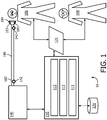
FIG. 1 schematically illustrates a system configured to ventilate a subject, according to one or more embodiments; and -
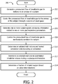
FIG. 2 illustrates a method of providing ventilation to a subject, according to one or more examples. - As used herein, the singular form of "a", "an", and "the" include plural references unless the context clearly dictates otherwise. As used herein, the statement that two or more parts or components are "coupled" shall mean that the parts are joined or operate together either directly or indirectly, i.e., through one or more intermediate parts or components, so long as a link occurs. As used herein, "directly coupled" means that two elements are directly in contact with each other. As used herein, "fixedly coupled" or "fixed" means that two components are coupled so as to move as one while maintaining a constant orientation relative to each other.
- As used herein, the word "unitary" means a component is created as a single piece or unit. That is, a component that includes pieces that are created separately and then coupled together as a unit is not a "unitary" component or body. As employed herein, the statement that two or more parts or components "engage" one another shall mean that the parts exert a force against one another either directly or through one or more intermediate parts or components. As employed herein, the term "number" shall mean one or an integer greater than one (i.e., a plurality).
- Directional phrases used herein, such as, for example and without limitation, top, bottom, left, right, upper, lower, front, back, and derivatives thereof, relate to the orientation of the elements shown in the drawings and are not limiting upon the claims unless expressly recited therein.
-
FIG. 1 schematically illustrates an exemplary embodiment of asystem 10 to ventilate asubject 106.System 10 includes one or more of apressure generator 140, auser interface 120, adelivery circuit 180,electronic storage 130, one ormore sensors 142, one ormore leak ports 183, one ormore processors 110, acontrol module 111, aparameter determination module 112, anestimation module 113, and/or other components. -
Pressure generator 140 ofsystem 10 inFIG. 1 may be integrated, combined, or connected with a ventilator system.Pressure generator 140 may be configured to provide a pressurized flow of breathable gas for delivery to the airway ofsubject 106, e.g. viadelivery circuit 180, to effect mechanical ventilation ofsubject 106, and/or to provide other therapeutic benefits. Typically, mechanical ventilation is provided to subjects not capable of properly breathing due to respiratory muscle weakness, neuromuscular disease, atrophy, and/or dysfunction.Subject 106 may or may not initiate one or more phases of respiration. For example, one or more examples may include active ventilation during inspiration and passive ventilation during exhalation. - During inspiration, the pressure of the pressurized flow of breathable gas may be adjusted to one or more inspiratory pressure levels to induce, support, and/or control inhalation by
subject 106. Alternatively, and/or additionally, during expiration, the pressure of the pressurized flow of breathable gas may be adjusted to one or more expiratory pressure levels to induce, support, and/or control exhalation bysubject 106.Pressure generator 140 is configured to adjust one or more of a pressure level, flow rate, humidity, velocity, acceleration, and/or other parameters of the pressurized flow of breathable gas. - A pressurized flow of breathable gas is delivered from
pressure generator 140 to the airway ofsubject 106 via adelivery circuit 180.Delivery circuit 180 may be configured to selectively control the direction and/or flow of breathable gas to and/or from the airway ofsubject 106.Delivery circuit 180 may be referred to assubject interface 180.Delivery circuit 180 may be configured to permit gas to be exhausted from the airway of subject 106 throughdelivery circuit 180 and/or any of its constituent components, e.g. to ambient atmosphere. -
Delivery circuit 180 may include aconduit 182, one ormore leak ports 183, asubject interface appliance 184, and/or other constituent components.Delivery circuit 180 and/or any of its constituent components may include, individually and/or jointly, a volume of dead space. For example, in some embodiments, at least some of the volume withinsubject interface appliance 184 may be part of the afore-mentioned volume of dead space. This volume of dead space may be referred to as Vds. -
Conduit 182 includes a flexible length of hose, or other conduit, either in a single-limb or multi-limb configuration that placessubject interface appliance 184 in fluid communication withpressure generator 140.Conduit 182 forms a flow path through which the pressurized flow of breathable gas (e.g. air) is communicated betweensubject interface appliance 184 andpressure generator 140. In some embodiments, at least some of the volume withinconduit 182 may be part of the afore-mentioned volume of dead space Vds. - One or
more leak ports 183, formed indelivery circuit 180, are configured to provide fluid communication between at least part of an interior ofdelivery circuit 180 and ambient atmosphere to facilitate mechanical ventilation. A leak port may be referred to as an exhalation port, a leak device, or an exhalation device. The mechanical ventilation through one ormore leak ports 183 may be passive. Fluid communication through a leak port may be intentional, e.g. to facilitate the removal of exhaled gas fromsystem 10. In some examples, the one ormore leak ports 183 are sufficiently large to allow gas to escape fast enough that a reduction in pressure of the pressurized flow of breathable gas induces exhalation. Although twoleak ports 183 are depicted inFIG. 1 , this exemplary depiction is not intended to be limiting in any way. In some examples, a leak port may include on or more of an orifice, an opening, a selectively closable opening, a partially closeable opening, a fluid connector, and/or other ways to fluidly communicate between an interior ofdelivery circuit 180 and ambient atmosphere to facilitate mechanical ventilation. Althoughleak ports 183 are depicted inFIG. 1 as integrated withinsubject interface appliance 184, this example is exemplary and not intended to be limiting in any way. For example, leak ports may be disposed elsewhere indelivery circuit 180 and/orsystem 10. -
Subject interface appliance 184 ofsystem 10 inFIG. 1 is configured to deliver the pressurized flow of breathable gas to the airway ofsubject 106. As such,subject interface appliance 184 may include any appliance suitable for this function. In some examples,pressure generator 140 is a dedicated ventilation device andsubject interface appliance 184 is configured to be removably coupled with another interface appliance being used to deliver respiratory therapy to subject 106. For example,subject interface appliance 184 may be configured to engage with and/or be inserted into an endotracheal tube, a tracheotomy portal, and/or other interface appliances. In one example,subject interface appliance 184 is configured to engage the airway ofsubject 106 without an intervening appliance. In this example,subject interface appliance 184 may include one or more of an endotracheal tube, a nasal cannula, a tracheotomy tube, a nasal mask, a nasal/oral mask, a full-face mask, a total facemask, and/or other interface appliances that communicate a flow of gas with an airway of a subject. The present disclosure is not limited to these examples, and contemplates delivery of the pressurized flow of breathable gas to subject 106 using any subject interface. -
Electronic storage 130 ofsystem 10 inFIG. 1 comprises electronic storage media that electronically stores information. The electronic storage media ofelectronic storage 130 may include one or both of system storage that is provided integrally (i.e., substantially non-removable) withsystem 10 and/or removable storage that is removably connectable tosystem 10 via, for example, a port (e.g., a USB port, a FireWire port, etc.), a slot (e.g., an SD card slot, etc.), or a drive (e.g., a disk drive, etc.).Electronic storage 130 may include one or more of optically readable storage media (e.g., optical disks, etc.), magnetically readable storage media (e.g., magnetic tape, magnetic hard drive, floppy drive, etc.), electrical charge-based storage media (e.g., EPROM, EEPROM, RAM, etc.), solid-state storage media (e.g., flash drive, etc.), and/or other electronically readable storage media.Electronic storage 130 may store software algorithms, information determined byprocessor 110, information received viauser interface 120, and/or other information that enablessystem 10 to function properly. For example,electronic storage 130 may record or store information pertaining to occurrences of the fraction of inhaled oxygen breaching a predetermined minimum oxygen threshold (as discussed elsewhere herein), and/or other information.Electronic storage 130 may be a separate component withinsystem 10, orelectronic storage 130 may be provided integrally with one or more other components of system 10 (e.g., processor 110). -
User interface 120 ofsystem 10 inFIG. 1 is configured to provide an interface betweensystem 10 and a user (e.g.,user 108, subject 106, a caregiver, a therapy decision-maker, etc.) through which the user can provide information to and receive information fromsystem 10. This enables data, results, and/or instructions and any other communicable items, collectively referred to as "information," to be communicated between the user andsystem 10. An example of information that may be conveyed touser 108 is a warning when the fraction of inhaled oxygen breaches a predetermined minimum oxygen threshold during ventilation. Examples of interface devices suitable for inclusion inuser interface 120 include a keypad, buttons, switches, a keyboard, knobs, levers, a display screen, an electronic display configured to display information, a touch screen, speakers, a microphone, an indicator light, an audible alarm, and a printer. Information may be provided touser 108 or subject 106 byuser interface 120 in the form of auditory signals, visual signals, tactile signals, and/or other sensory signals. - It is to be understood that other communication techniques, either hardwired or wireless, are also contemplated herein as
user interface 120. For example, in one example,user interface 120 may be integrated with a removable storage interface provided byelectronic storage 130. In this example, information is loaded intosystem 10 from removable storage (e.g., a smart card, a flash drive, a removable disk, etc.) that enables the user(s) to customizesystem 10. Other exemplary input devices and techniques adapted for use withsystem 10 asuser interface 120 include, but are not limited to, an RS-232 port, RF link, an IR link, modem (telephone, cable, Ethernet, internet or other). In short, any technique for communicating information withsystem 10 is contemplated asuser interface 120. - One or
more sensors 142 ofsystem 10 inFIG. 1 are configured to generate output signals conveying measurements related to gas parameters. These gas parameters may include one or more of flow rate, (airway) pressure, humidity, velocity, acceleration, and/or other gas or respiratory parameters. These parameters may pertain to one or more gas levels of the pressurized flow of breathable gas provided throughpressure generator 140 and/or a flow of gas at or near the airway ofsubject 106, for example withindelivery circuit 180. One ormore sensors 142 may be in fluid communication withconduit 182 and/orsubject interface appliance 184. - The illustration of
sensor 142 including two members inFIG. 1 is not intended to be limiting. The illustration of asensor 142 at or nearsubject interface appliance 184 is not intended to be limiting. The illustration of asensor 142 at or nearpressure generator 140 is not intended to be limiting. In oneexample sensor 142 includes a plurality of sensors operating as described above by generating output signals conveying information related to parameters associated with the state and/or condition of an airway ofsubject 106, the breathing ofsubject 106, the gas breathed bysubject 106, the composition of the gas breathed bysubject 106, the delivery of the gas to the airway ofsubject 106, and/or a respiratory effort by the subject. For example, a parameter may be related to a mechanical unit of measurement of a component of pressure generator 140 (or of a device that pressuregenerator 140 is integrated, combined, or coupled with) such as valve drive current, rotor speed, motor speed, blower speed, fan speed, or a related measurement that may serve as a proxy for any of the previously listed parameters through a previously known and/or calibrated mathematical relationship. Resulting signals or information from one ormore sensors 142 may be transmitted toprocessor 110,user interface 120,electronic storage 130, and/or other components ofsystem 10. This transmission may be wired and/or wireless. -
Processor 110 ofsystem 10 inFIG. 1 is configured to provide information processing capabilities insystem 10. As such,processor 110 includes one or more of a digital processor, an analog processor, a digital circuit designed to process information, an analog circuit designed to process information, a state machine, and/or other mechanisms for electronically processing information. Althoughprocessor 110 is depicted inFIG. 1 as a single entity, this is for illustrative purposes only. In some examples,processor 110 includes a plurality of processing units. - As is shown in
FIG. 1 ,processor 110 is configured to execute one or more computer program modules. The one or more computer program modules include one or more ofcontrol module 111,parameter determination module 112,estimation module 113, and/or other modules.Processor 110 may be configured to execute modules 111-113 by software; hardware; firmware; some combination of software, hardware, and/or firmware; and/or other mechanisms for configuring processing capabilities onprocessor 110. - It should be appreciated that although modules 111-113 are illustrated in
FIG. 1 as being co-located within a single processing unit, in examples in whichprocessor 110 includes multiple processing units, one or more of modules 111-113 may be located remotely from the other modules. The description of the functionality provided by the different modules 111-113 described herein is for illustrative purposes, and is not intended to be limiting, as any of modules 111-113 may provide more or less functionality than is described. For example, one or more of modules 111-113 may be eliminated, and some or all of its functionality may be incorporated, shared, integrated into, and/or otherwise provided by other ones of modules 111-113. Note thatprocessor 110 may be configured to execute one or more additional modules that may perform some or all of the functionality attributed below to one of modules 111-113. -
Control module 111 ofsystem 10 inFIG. 1 is configured to control operation ofsystem 10 to at least partially mechanically ventilate subject 106. Mechanically ventilating subject 106 may include adjusting pressure levels to induce, support, and/or control one or both of inhalation and/or exhalation bysubject 106.Control module 111 may be configured to control the pressure generator to adjust one or more levels of one or more gas parameters of the pressurized flow of breathable gas in accordance with one or more of a (respiratory) therapy regimen, one or more algorithms that control adjustments and/or changes in the pressurized flow of breathable gas, and/or other factors.Control module 111 may be configured to controlpressure generator 140 such that one or more gas parameters of the pressurized flow of breathable gas are varied over time in accordance with a respiratory therapy regimen and/or treatment.Control module 111 may be configured to controlpressure generator 140 to provide the pressurized flow of breathable gas at inspiratory pressure levels during inhalation phases, and/or at expiratory pressure levels during exhalation phases (e.g. positive end expiratory pressure, or PEEP). Parameters determined byparameter determination module 112 and/or received through one ormore sensors 142 may be used bycontrol module 111, e.g. in a feedback manner, to adjust therapy modes/settings/operations ofsystem 10. Alternatively, and/or simultaneously, signals and/or information received throughuser interface 120 may be used bycontrol module 111, e.g. in a feedback manner, to adjust one or more therapy modes/settings/operations ofsystem 10. - In some examples,
user 108 and/or subject 106 may (e.g. manually) control one or more pressure levels used during operation ofsystem 10, e.g. throughuser interface 120.Control module 111 may be configured to time its operations relative to the transitional moments in the breathing cycle of a subject, over multiple breath cycles, and/or in any other relation to any detected events and/or occurrences during operation ofsystem 10. - In some examples, operation of
control module 111 may be governed through programmatic control, e.g. by an algorithm implemented through instructions that are executed bycontrol module 111. Such an algorithm may be designed to titrate operating conditions ofsystem 10 such that a target operating condition is reached and/or accomplished over time. For example, the algorithm may use a target inhalation tidal volume (e.g. inhaled tidal volume) for individual inhalations. The algorithm may adjust one or more gas parameters of the pressurized flow of breathable gas accordingly, such as, e.g., inspiratory pressure level and/or inhalation period. -
Parameter determination module 112 ofsystem 10 inFIG. 1 is configured to determine one or more gas parameters, respiratory parameters, and/or other parameters from output signals generated by sensor(s) 142. The one or more gas parameter may include and/or be related to one or more of (peak) flow, flow rate, (tidal) volume, pressure, temperature, humidity, velocity, acceleration, gas composition (e.g. concentration(s) of one or more constituents such as, e.g., CO2), thermal energy dissipated, (intentional) gas leak, and/or other measurements related to the (pressurized) flow of breathable gas. One or more respiratory parameters may be derived from gas parameters and/or other output signals conveying measurements of the pressurized flow of breathable gas. The one or more respiratory parameters may include one or more of respiratory rate, breathing period, inhalation time or period, exhalation time or period, respiration flow curve shape, transition time from inhalation to exhalation and/or vice versa, transition time from peak inhalation flow rate to peak exhalation flow rate and/or vice versa, respiration pressure curve shape, maximum proximal pressure drop (per breathing cycle and/or phase), peak cough flow, average (or otherwise aggregated) cough flow, inhaled tidal volume (per inhalation), exhaled tidal volume (per exhalation), leaked exhalation volume (e.g. through one ormore leak ports 183, per exhalation), leaked inhalation volume (e.g. through one ormore leak ports 183, per inhalation), and/or other respiratory parameters. Parameters may be determined on a breath-by-breath basis, on a cough-by-cough basis, per individual respiratory phase, and/or at other intervals. - In some examples,
parameter determination module 112 may be configured to determine and/or estimate a leak indelivery circuit 180 and/or another component ofsystem 10. As used herein a leak may be intentional (e.g. through one or more leak ports 183) or unintentional (e.g. at or near the engagement ofsubject interface appliance 184 and the airway of subject 106). For example, leaks may refer to fluid communication between (the interior of) any component ofsystem 10 and ambient air. During exhalations,parameter determination module 112 may be configured to determine, based on the generated output signals, a leaked exhalation volume, e.g. through one ormore leak ports 183. During inhalations,parameter determination module 112 may be configured to determine, based on the generated output signals, a leaked inhalation volume, e.g. through one ormore leak ports 183. According to the invention, leak flow rate Qleak is approximated using the following version of the Blasius equation:
Qleak = 6.3·P 4/ 7, for delivered pressure, P - The leaked exhalation volume is based on, at least, leak flow rate Qleak and the duration of exhalation. The leaked inhalation volume is based on, at least, leak flow rate Qleak and the duration of inhalation. In one example, depending on the nature, shape, location, and/or
size ofleak ports 183,parameter determination module 112 may be configured to compensate accordingly when determining parameters that are related to a leak insystem 10. -
Estimation module 113 is configured to estimate a fraction of inhaled oxygen FiO2 during inhalations. To begin, for individual exhalations, a mole fraction of oxygen within the volume of dead space Vds is determined and/or estimated based on a comparison of an individual exhalation tidal volume Vte with a combination of the leaked exhalation volume J Qleak during a particular individual exhalation and Vds. In some embodiments, mole fractions of oxygen of inhaled air χair and exhaled air χvte may be assumed to be 0.21 and 0.16, respectively. Note that other operating conditions are contemplated within the scope of this disclosure, including the use of oxygen-enriched breathable gas withinsystem 10. The mole fraction of oxygen within the volume of dead space at the end of an individual exhalation or at the start of the subsequent inhalation may be referred to as χstart_of_insp. Note that embodiments that compensate for leaking of breathable gas from Vds during periods between inhalations and exhalations (and/or vice versa) are contemplated within the scope of this disclosure. χstart_of_insp may be approximated using the following equation:
- In the preceding equation, total exhalation volume Vtot_exp may be approximated using the following equation:

- In some embodiments, ideal blending within volume of dead space Vds may be assumed. Note that other operating conditions are contemplated within the scope of this disclosure, including imperfect blending of ambient air and exhaled air within Vds.
- Once χstart_of_insp is determined and/or estimated,
estimation module 113 is configured to estimate the fraction of inhaled oxygen FiO2 based on a comparison of an individual inhalation tidal volume Vti with a combination of the leaked inhalation volume J Qleak during a particular individual inhalation and Vds. Note that the particular individual inhalation may immediately follow the particular individual exhalation that was used to determine χstart_of_insp, as described previously. FiO2 may be approximated using the following equation:
- In some examples, information based on estimated fraction of inhaled oxygen FiO2 may be displayed for presentation to subject 106 and/or
user 108, e.g. throughuser interface 120. In some examples, FiO2 may be compared to a predetermined minimum oxygen threshold, e.g. for individual inhalations. The predetermined minimum oxygen threshold may be about 19%, 19.5%, 20%, 20.1%, 20.2%, 20.3%, 20.4%, 20.5%, 20.6%, 20.7% and/or about another threshold of a mole fraction of oxygen, as may be suitable and/or appropriate for the operating conditions ofsystem 10 and/or the condition ofsubject 106. -
Estimation module 113 may be further configured to determine a fraction of inhaled carbon dioxide during individual inhalations, based on the estimated fraction of inhaled oxygen FiO2, e.g. reciprocally. In other words, a decrease in the fraction of inhaled oxygen may correspond to an increase in the fraction of inhaled carbon dioxide. - Responsive to FiO2 breaching the predetermined minimum oxygen threshold,
system 10 and/or its constituent components may be configured to take one or more of the following actions: alarm and/or notify subject 106 and/oruser 108, increase removal of carbon dioxide fromsystem 10, reduce rebreathing, increase fall time, increase inhalation period, increase the positive end expiratory pressure level, and/or take other (corrective) actions and/or precautions.System 10 and/or its constituent components may be configured to take one or more of these actions in a predetermined order of escalation. - The positive end expiratory pressure may be set and/or raised to a predetermined PEEP level. Using a positive end expiratory pressure may reduce the probability of FiO2 breaching the predetermined minimum oxygen threshold. An appropriate predetermined PEEP level may be based on various operating conditions of
system 10, including the size ofleak ports 183. The predetermined PEEP level may be about 2 cmH2O, about 3 cmH2O, about 3.5 cmH2O, about 4 cmH2O, about 4.5 cmH2O, about 5 cmH2O, and/or another pressure level. Monitoring FiO2 as described herein may provide increased responsiveness to potential patient discomfort, e.g. when compared to traditional SpO2 monitoring. - In a preferred example,
system 10 operates on a breath-by-breath basis. Note that this is not intended to be limiting. For example, in some examples, a fraction of inhaled oxygen may be estimated, determined, and/or aggregated over multiple inhalations and/or multiple exhalations. -
FIG. 2 illustrates amethod 200 of ventilating a subject. The operations ofmethod 200 presented below are intended to be illustrative. In some examples,method 200 may be accomplished with one or more additional operations not described, and/or without one or more of the operations discussed. Additionally, the order in which the operations ofmethod 200 are illustrated inFIG. 2 and described below is not intended to be limiting. - In some examples,
method 200 may be implemented in one or more processing devices (e.g., a digital processor, an analog processor, a digital circuit designed to process information, an analog circuit designed to process information, a state machine, and/or other mechanisms for electronically processing information). The one or more processing devices may include one or more devices executing some or all of the operations ofmethod 200 in response to instructions stored electronically on an electronic storage medium. The one or more processing devices may include one or more devices configured through hardware, firmware, and/or software to be specifically designed for execution of one or more of the operations ofmethod 200. - At an
operation 202, a pressurized flow of breathable gas is generated for delivery to the airway of a subject. In some examples,operation 202 is performed by a pressure generator the same as or similar to pressure generator 140 (shown inFIG. 1 and described herein). - At an
operation 204, the pressurized flow of breathable gas is guided to the airway of the subject through a volume of dead space. In some examples,operation 204 is performed by a delivery circuit the same as or similar to delivery circuit 180 (shown inFIG. 1 and described herein). - At an
operation 206, one or more output signals are generated that convey information related to flow rate and/or pressure in the delivery circuit/subject interface. In some examples,operation 206 is performed by a sensor the same as or similar to sensor 142 (shown inFIG. 1 and described herein). - At an
operation 208, the pressurized flow of breathable gas is controlled to at least partially mechanically ventilate the subject. In some examples,operation 208 is performed by a control module the same as or similar to control module 111 (shown inFIG. 1 and described herein). - At an
operation 210, an exhaled tidal volume and leaked exhalation volume is determined during an exhalation. In some examples,operation 210 is performed by a parameter determination module the same as or similar to parameter determination module 112 (shown inFIG. 1 and described herein). - At an
operation 212, an inhaled tidal volume and leaked inhalation volume is determined during a subsequent inhalation. In some examples,operation 212 is performed by a parameter determination module the same as or similar to parameter determination module 112 (shown inFIG. 1 and described herein). - At an
operation 214, a fraction in inhaled oxygen is determined. The fraction of inhaled oxygen is based on a first comparison of the exhaled tidal volume with a combination of the volume of dead space and the leaked exhalation volume. The fraction of inhaled oxygen is further based on a second comparison of the inhaled tidal volume with a combination of the volume of the dead space and the leaked inhalation volume. In some examples,operation 214 is performed by an estimation module the same as or similar to estimation module 113 (shown inFIG. 1 and described herein). - It will be appreciated that the description of the operation of
pressure generator 140 by theelectronic processor 110 and/or its modules is not intended to be limiting. Other controllers for openingpressure generator 140 responsive to
pressurization alongdelivery circuit 180 fall within the scope of this disclosure. Other mechanical controllers are also contemplated. - In the claims, any reference signs placed between parentheses shall not be construed as limiting the claim. The word "comprising" or "including" does not exclude the presence of elements or steps other than those listed in a claim. In a device claim enumerating several means, several of these means may be embodied by one and the same item of hardware. The word "a" or "an" preceding an element does not exclude the presence of a plurality of such elements. In any device claim enumerating several means, several of these means may be embodied by one and the same item of hardware. The mere fact that certain elements are recited in mutually different dependent claims does not indicate that these elements cannot be used in combination.
- Although the description provided above provides detail for the purpose of illustration based on what is currently considered to be the most practical and preferred embodiments, it is to be understood that such detail is solely for that purpose and that the disclosure is not limited to the expressly disclosed embodiments, but, on the contrary, is intended to cover modifications and equivalent arrangements that are within the scope of the appended claims. For example, it is to be understood that the present disclosure contemplates that, to the extent possible, one or more features of any embodiment can be combined with one or more features of any other embodiment.
Claims (9)
- A ventilator comprising;(a) a pressure generator (140) configured to generate a pressurized flow of breathable gas for delivery to an airway of the subject (106);(b) a subject interface (180) configured to guide the pressurized flow of breathable gas to the airway of the subject, wherein the subject interface includes a volume of dead space;(c) one or more sensors (142) configured to generate output signals conveying information related to flow rate and/or pressure in the subject interface; and(d) one or more processors (110) configured to execute computer program modules, the computer program modules comprising:(i) a control module (111) configured to control the pressure generator to generate the pressurized flow of breathable gas to at least partially mechanically ventilate the subject;characterized in that the computer program modules further comprise:(ii) a parameter determination module (112) configured to:(1) determine, based on the output signals generated during an exhalation, an exhaled tidal volume and a leaked exhalation volume, and(2) determine, based on the output signals generated during a subsequent inhalation, an inhaled tidal volume and a leaked inhalation volume;(iii) an estimation module (113) configured to estimate a fraction of inhaled oxygen during the subsequent inhalation based on a first comparison of the exhaled tidal volume with a combination of the volume of dead space and the leaked exhalation volume, and further based on a second comparison of the inhaled tidal volume with a combination of the volume of dead space and the leaked inhalation volume.
- The ventilator of claim 1, wherein the control module (111) is further configured to increase the positive end expiratory pressure level, responsive to the fraction of inhaled oxygen breaching a predetermined minimum oxygen threshold.
- The ventilator of claim 1, further comprising:
one or more leak ports (183) formed in the subject interface (180) configured to provide fluid communication between an interior of the subject interface and ambient atmosphere to facilitate passive mechanical ventilation. - The ventilator of claim 1, wherein the estimation module (113) is further configured to estimate a fraction of inhaled carbon dioxide during the subsequent inhalation based on the estimated fraction of inhaled oxygen.
- The ventilator of claim 1, wherein the estimation module (113) is further configured to estimate a mole fraction of oxygen in the volume of dead space based on the first comparison, wherein estimation of the fraction of inhaled oxygen is further based on the estimated mole fraction of oxygen in the volume of dead space.
- The ventilator of claim 1, wherein the fraction of inhaled oxygen FiO2 is approximated using the equation:


- The ventilator of claim 6, wherein χstar_of_insp is approximated using the equation:


- The ventilator of claim 7, wherein Vtot_exp is approximated using the equation:

- The ventilator of claim 7, wherein χair is 0.21 and χvte is 0.16.
Applications Claiming Priority (2)
| Application Number | Priority Date | Filing Date | Title |
|---|---|---|---|
| US201261645825P | 2012-05-11 | 2012-05-11 | |
| PCT/IB2013/053196 WO2013168036A1 (en) | 2012-05-11 | 2013-04-23 | Systems and methods to determine the fraction of inhaled oxygen during ventilation. |
Publications (2)
| Publication Number | Publication Date |
|---|---|
| EP2846861A1 EP2846861A1 (en) | 2015-03-18 |
| EP2846861B1 true EP2846861B1 (en) | 2019-04-10 |
Family
ID=48700643
Family Applications (1)
| Application Number | Title | Priority Date | Filing Date |
|---|---|---|---|
| EP13732238.4A Active EP2846861B1 (en) | 2012-05-11 | 2013-04-23 | Systems to determine the fraction of inhaled oxygen during ventilation. |
Country Status (7)
| Country | Link |
|---|---|
| US (1) | US9950132B2 (en) |
| EP (1) | EP2846861B1 (en) |
| JP (1) | JP6486821B2 (en) |
| CN (1) | CN104284691B (en) |
| BR (1) | BR112014027680A2 (en) |
| RU (1) | RU2014150090A (en) |
| WO (1) | WO2013168036A1 (en) |
Families Citing this family (4)
| Publication number | Priority date | Publication date | Assignee | Title |
|---|---|---|---|---|
| WO2017025869A1 (en) * | 2015-08-10 | 2017-02-16 | Koninklijke Philips N.V. | Simplified display of end-tidal co2 |
| CN106237467A (en) * | 2016-08-26 | 2016-12-21 | 深圳市安保科技有限公司 | The vent method of a kind of breathing apparatus and device |
| EP3531912B1 (en) * | 2016-12-05 | 2020-11-11 | Medipines Corporation | Method and device for respiratory measurements using breathing gas samples |
| DE102018008493A1 (en) * | 2018-10-30 | 2020-04-30 | Drägerwerk AG & Co. KGaA | Transfer unit, ventilation device, ventilation system and method for changing a ventilation device used for a patient's ventilation process |
Family Cites Families (29)
| Publication number | Priority date | Publication date | Assignee | Title |
|---|---|---|---|---|
| US4340044A (en) * | 1980-03-20 | 1982-07-20 | Berkshire Research Partners | Volume ventilator |
| US5701883A (en) * | 1996-09-03 | 1997-12-30 | Respironics, Inc. | Oxygen mixing in a blower-based ventilator |
| US8932227B2 (en) | 2000-07-28 | 2015-01-13 | Lawrence A. Lynn | System and method for CO2 and oximetry integration |
| US7073501B2 (en) | 1999-02-04 | 2006-07-11 | Univerity Technologies International Inc. | Ventilatory stabilization technology |
| US6752150B1 (en) * | 1999-02-04 | 2004-06-22 | John E. Remmers | Ventilatory stabilization technology |
| US6512938B2 (en) * | 2000-12-12 | 2003-01-28 | Nelson R. Claure | System and method for closed loop controlled inspired oxygen concentration |
| FR2831825B1 (en) | 2001-11-08 | 2004-01-30 | Intertechnique Sa | DILUTION CONTROL METHOD AND DEVICE FOR RESPIRATORY APPARATUS |
| DE10161057A1 (en) * | 2001-12-12 | 2003-07-10 | Heptec Gmbh | Process for controlling the differential pressure in a CPAP device and CPAP device |
| JP2009506825A (en) * | 2005-09-02 | 2009-02-19 | テクニオン・リサーチ・アンド・ディベロップメント・ファウンデーション・リミテッド | Method and apparatus for monitoring vital capacity |
| US8006692B2 (en) | 2005-12-02 | 2011-08-30 | Carefusion 2200, Inc. | Gas blender with auxiliary mixed gas outlet |
| CN101365509A (en) | 2005-12-14 | 2009-02-11 | 莫哲奈特医疗公司 | High flow therapy device |
| US7788963B2 (en) | 2006-10-31 | 2010-09-07 | Ric Investments, Llc | System and method for calibrating a determination of partial pressure of one or more gaseous analytes |
| WO2010150264A1 (en) | 2009-06-24 | 2010-12-29 | Oridion Medical 1987 Ltd. | Integrated pulmonary index for weaning from mechanical ventilation |
| US20080202518A1 (en) * | 2007-02-23 | 2008-08-28 | General Electric Company | Setting mandatory mechanical ventilation parameters based on patient physiology |
| CA2691377A1 (en) | 2007-06-29 | 2009-01-08 | Mermaid Care A/S | A gas mixing device for an air-way management system |
| US20090107500A1 (en) * | 2007-10-25 | 2009-04-30 | Sequal Technologies, Inc. | Portable Oxygen Concentrator System and Method Including Concentrated Oxygen Flow Delivery |
| WO2009058083A1 (en) * | 2007-10-29 | 2009-05-07 | Poseidon Diving Systems | Auto calibration / validation of oxygen sensor in breathing apparatus |
| US10750738B2 (en) | 2008-01-31 | 2020-08-25 | Transmedics, Inc. | Systems and methods for ex vivo lung care |
| US8272380B2 (en) | 2008-03-31 | 2012-09-25 | Nellcor Puritan Bennett, Llc | Leak-compensated pressure triggering in medical ventilators |
| WO2009123981A1 (en) * | 2008-03-31 | 2009-10-08 | Nellcor Puritan Bennett Llc | Leak-compensated proportional assist ventilation |
| WO2009124198A2 (en) * | 2008-04-02 | 2009-10-08 | Mergenet Medical, Inc. | Clinical monitoring in open respiratory airways |
| CN102056539B (en) | 2008-06-06 | 2015-10-07 | 柯惠有限合伙公司 | For making great efforts with patient the system and method that carries out pro rata taking a breath |
| US9278185B2 (en) | 2008-09-04 | 2016-03-08 | Caire Inc. | System and method for controlling bolus pulse duration based on inspiratory time in an oxygen concentation system |
| CN102361661B (en) | 2009-03-23 | 2015-09-02 | 皇家飞利浦电子股份有限公司 | Gas mixing control apparatus and method |
| US8550077B2 (en) | 2009-05-19 | 2013-10-08 | The Cleveland Clinic Foundation | Ventilator control system utilizing a mid-frequency ventilation pattern |
| WO2010140072A1 (en) * | 2009-06-03 | 2010-12-09 | Koninklijke Philips Electronics, N.V. | System and method for controlling leakage of a circuit delivering a pressurized flow of breathable gas to a subject |
| WO2012014106A1 (en) * | 2010-07-27 | 2012-02-02 | Koninklijke Philips Electronics N.V. | Leak estimation using function estimation. |
| US20120090611A1 (en) * | 2010-10-13 | 2012-04-19 | Nellcor Puritan Bennett Llc | Systems And Methods For Controlling An Amount Of Oxygen In Blood Of A Ventilator Patient |
| RU2013133854A (en) | 2010-12-21 | 2015-01-27 | Конинклейке Филипс Электроникс Н.В. | SYSTEM AND METHOD FOR DETERMINING CARBON DIOXIDE DISTRIBUTED IN THE PROCESS OF NON-INVASIVE LUNG VENTILATION |
-
2013
- 2013-04-23 JP JP2015510905A patent/JP6486821B2/en active Active
- 2013-04-23 BR BR112014027680A patent/BR112014027680A2/en not_active IP Right Cessation
- 2013-04-23 US US14/398,925 patent/US9950132B2/en active Active
- 2013-04-23 EP EP13732238.4A patent/EP2846861B1/en active Active
- 2013-04-23 CN CN201380024710.1A patent/CN104284691B/en active Active
- 2013-04-23 RU RU2014150090A patent/RU2014150090A/en not_active Application Discontinuation
- 2013-04-23 WO PCT/IB2013/053196 patent/WO2013168036A1/en active Application Filing
Non-Patent Citations (1)
| Title |
|---|
| None * |
Also Published As
| Publication number | Publication date |
|---|---|
| US20150107593A1 (en) | 2015-04-23 |
| JP2015519119A (en) | 2015-07-09 |
| JP6486821B2 (en) | 2019-03-20 |
| CN104284691B (en) | 2017-05-10 |
| EP2846861A1 (en) | 2015-03-18 |
| BR112014027680A2 (en) | 2017-06-27 |
| WO2013168036A1 (en) | 2013-11-14 |
| RU2014150090A (en) | 2016-07-10 |
| US9950132B2 (en) | 2018-04-24 |
| CN104284691A (en) | 2015-01-14 |
Similar Documents
| Publication | Publication Date | Title |
|---|---|---|
| EP3585465B1 (en) | Automatic peep selection for mechanical ventilation | |
| US9987444B2 (en) | System and method for limited flow respiratory therapy | |
| US9320863B2 (en) | System and method for inexsufflating a subject | |
| JP6223340B2 (en) | Method and apparatus for controlling a ventilator device | |
| US10335564B2 (en) | System and method for controlling exsufflation pressure during in-exsufflation | |
| US10821245B2 (en) | Pressure support system for breath stacking therapy | |
| US11202875B2 (en) | Cough assistance and measurement system and method | |
| EP3209357B1 (en) | System for controlling leak | |
| JP2015520648A5 (en) | ||
| EP2846861B1 (en) | Systems to determine the fraction of inhaled oxygen during ventilation. | |
| US20140326242A1 (en) | Sysems and methods for using partial co2 rebreathing integrated in a ventilator and measurements thereof to determine noninvasive cardiac output | |
| JP2015519119A5 (en) | ||
| EP2688620B1 (en) | Systems to manage central sleep apnea by controlling accumulated retrograde volume | |
| US10881821B2 (en) | Mechanical ventilation based on alveolar ventilation |
Legal Events
| Date | Code | Title | Description |
|---|---|---|---|
| PUAI | Public reference made under article 153(3) epc to a published international application that has entered the european phase |
Free format text: ORIGINAL CODE: 0009012 |
|
| 17P | Request for examination filed |
Effective date: 20141211 |
|
| AK | Designated contracting states |
Kind code of ref document: A1 Designated state(s): AL AT BE BG CH CY CZ DE DK EE ES FI FR GB GR HR HU IE IS IT LI LT LU LV MC MK MT NL NO PL PT RO RS SE SI SK SM TR |
|
| AX | Request for extension of the european patent |
Extension state: BA ME |
|
| DAX | Request for extension of the european patent (deleted) | ||
| STAA | Information on the status of an ep patent application or granted ep patent |
Free format text: STATUS: EXAMINATION IS IN PROGRESS |
|
| 17Q | First examination report despatched |
Effective date: 20170908 |
|
| RIC1 | Information provided on ipc code assigned before grant |
Ipc: A61B 5/091 20060101ALI20180726BHEP Ipc: A61B 5/083 20060101ALI20180726BHEP Ipc: A61B 5/097 20060101ALI20180726BHEP Ipc: A61M 16/00 20060101AFI20180726BHEP |
|
| GRAP | Despatch of communication of intention to grant a patent |
Free format text: ORIGINAL CODE: EPIDOSNIGR1 |
|
| STAA | Information on the status of an ep patent application or granted ep patent |
Free format text: STATUS: GRANT OF PATENT IS INTENDED |
|
| INTG | Intention to grant announced |
Effective date: 20181026 |
|
| RIN1 | Information on inventor provided before grant (corrected) |
Inventor name: TRUSCHEL, WILLIAM, A. |
|
| GRAS | Grant fee paid |
Free format text: ORIGINAL CODE: EPIDOSNIGR3 |
|
| GRAA | (expected) grant |
Free format text: ORIGINAL CODE: 0009210 |
|
| STAA | Information on the status of an ep patent application or granted ep patent |
Free format text: STATUS: THE PATENT HAS BEEN GRANTED |
|
| AK | Designated contracting states |
Kind code of ref document: B1 Designated state(s): AL AT BE BG CH CY CZ DE DK EE ES FI FR GB GR HR HU IE IS IT LI LT LU LV MC MK MT NL NO PL PT RO RS SE SI SK SM TR |
|
| REG | Reference to a national code |
Ref country code: GB Ref legal event code: FG4D |
|
| REG | Reference to a national code |
Ref country code: CH Ref legal event code: EP Ref country code: AT Ref legal event code: REF Ref document number: 1117852 Country of ref document: AT Kind code of ref document: T Effective date: 20190415 |
|
| REG | Reference to a national code |
Ref country code: IE Ref legal event code: FG4D |
|
| REG | Reference to a national code |
Ref country code: DE Ref legal event code: R096 Ref document number: 602013053659 Country of ref document: DE |
|
| REG | Reference to a national code |
Ref country code: NL Ref legal event code: MP Effective date: 20190410 |
|
| REG | Reference to a national code |
Ref country code: LT Ref legal event code: MG4D |
|
| REG | Reference to a national code |
Ref country code: AT Ref legal event code: MK05 Ref document number: 1117852 Country of ref document: AT Kind code of ref document: T Effective date: 20190410 |
|
| PG25 | Lapsed in a contracting state [announced via postgrant information from national office to epo] |
Ref country code: NL Free format text: LAPSE BECAUSE OF FAILURE TO SUBMIT A TRANSLATION OF THE DESCRIPTION OR TO PAY THE FEE WITHIN THE PRESCRIBED TIME-LIMIT Effective date: 20190410 |
|
| PG25 | Lapsed in a contracting state [announced via postgrant information from national office to epo] |
Ref country code: SE Free format text: LAPSE BECAUSE OF FAILURE TO SUBMIT A TRANSLATION OF THE DESCRIPTION OR TO PAY THE FEE WITHIN THE PRESCRIBED TIME-LIMIT Effective date: 20190410 Ref country code: HR Free format text: LAPSE BECAUSE OF FAILURE TO SUBMIT A TRANSLATION OF THE DESCRIPTION OR TO PAY THE FEE WITHIN THE PRESCRIBED TIME-LIMIT Effective date: 20190410 Ref country code: LT Free format text: LAPSE BECAUSE OF FAILURE TO SUBMIT A TRANSLATION OF THE DESCRIPTION OR TO PAY THE FEE WITHIN THE PRESCRIBED TIME-LIMIT Effective date: 20190410 Ref country code: ES Free format text: LAPSE BECAUSE OF FAILURE TO SUBMIT A TRANSLATION OF THE DESCRIPTION OR TO PAY THE FEE WITHIN THE PRESCRIBED TIME-LIMIT Effective date: 20190410 Ref country code: AL Free format text: LAPSE BECAUSE OF FAILURE TO SUBMIT A TRANSLATION OF THE DESCRIPTION OR TO PAY THE FEE WITHIN THE PRESCRIBED TIME-LIMIT Effective date: 20190410 Ref country code: NO Free format text: LAPSE BECAUSE OF FAILURE TO SUBMIT A TRANSLATION OF THE DESCRIPTION OR TO PAY THE FEE WITHIN THE PRESCRIBED TIME-LIMIT Effective date: 20190710 Ref country code: PT Free format text: LAPSE BECAUSE OF FAILURE TO SUBMIT A TRANSLATION OF THE DESCRIPTION OR TO PAY THE FEE WITHIN THE PRESCRIBED TIME-LIMIT Effective date: 20190910 Ref country code: FI Free format text: LAPSE BECAUSE OF FAILURE TO SUBMIT A TRANSLATION OF THE DESCRIPTION OR TO PAY THE FEE WITHIN THE PRESCRIBED TIME-LIMIT Effective date: 20190410 |
|
| PG25 | Lapsed in a contracting state [announced via postgrant information from national office to epo] |
Ref country code: BG Free format text: LAPSE BECAUSE OF FAILURE TO SUBMIT A TRANSLATION OF THE DESCRIPTION OR TO PAY THE FEE WITHIN THE PRESCRIBED TIME-LIMIT Effective date: 20190710 Ref country code: PL Free format text: LAPSE BECAUSE OF FAILURE TO SUBMIT A TRANSLATION OF THE DESCRIPTION OR TO PAY THE FEE WITHIN THE PRESCRIBED TIME-LIMIT Effective date: 20190410 Ref country code: LV Free format text: LAPSE BECAUSE OF FAILURE TO SUBMIT A TRANSLATION OF THE DESCRIPTION OR TO PAY THE FEE WITHIN THE PRESCRIBED TIME-LIMIT Effective date: 20190410 Ref country code: GR Free format text: LAPSE BECAUSE OF FAILURE TO SUBMIT A TRANSLATION OF THE DESCRIPTION OR TO PAY THE FEE WITHIN THE PRESCRIBED TIME-LIMIT Effective date: 20190711 Ref country code: RS Free format text: LAPSE BECAUSE OF FAILURE TO SUBMIT A TRANSLATION OF THE DESCRIPTION OR TO PAY THE FEE WITHIN THE PRESCRIBED TIME-LIMIT Effective date: 20190410 |
|
| REG | Reference to a national code |
Ref country code: CH Ref legal event code: PL |
|
| REG | Reference to a national code |
Ref country code: BE Ref legal event code: MM Effective date: 20190430 |
|
| PG25 | Lapsed in a contracting state [announced via postgrant information from national office to epo] |
Ref country code: AT Free format text: LAPSE BECAUSE OF FAILURE TO SUBMIT A TRANSLATION OF THE DESCRIPTION OR TO PAY THE FEE WITHIN THE PRESCRIBED TIME-LIMIT Effective date: 20190410 Ref country code: IS Free format text: LAPSE BECAUSE OF FAILURE TO SUBMIT A TRANSLATION OF THE DESCRIPTION OR TO PAY THE FEE WITHIN THE PRESCRIBED TIME-LIMIT Effective date: 20190810 Ref country code: LU Free format text: LAPSE BECAUSE OF NON-PAYMENT OF DUE FEES Effective date: 20190423 |
|
| REG | Reference to a national code |
Ref country code: DE Ref legal event code: R097 Ref document number: 602013053659 Country of ref document: DE |
|
| PG25 | Lapsed in a contracting state [announced via postgrant information from national office to epo] |
Ref country code: DK Free format text: LAPSE BECAUSE OF FAILURE TO SUBMIT A TRANSLATION OF THE DESCRIPTION OR TO PAY THE FEE WITHIN THE PRESCRIBED TIME-LIMIT Effective date: 20190410 Ref country code: LI Free format text: LAPSE BECAUSE OF NON-PAYMENT OF DUE FEES Effective date: 20190430 Ref country code: MC Free format text: LAPSE BECAUSE OF FAILURE TO SUBMIT A TRANSLATION OF THE DESCRIPTION OR TO PAY THE FEE WITHIN THE PRESCRIBED TIME-LIMIT Effective date: 20190410 Ref country code: CH Free format text: LAPSE BECAUSE OF NON-PAYMENT OF DUE FEES Effective date: 20190430 Ref country code: CZ Free format text: LAPSE BECAUSE OF FAILURE TO SUBMIT A TRANSLATION OF THE DESCRIPTION OR TO PAY THE FEE WITHIN THE PRESCRIBED TIME-LIMIT Effective date: 20190410 Ref country code: RO Free format text: LAPSE BECAUSE OF FAILURE TO SUBMIT A TRANSLATION OF THE DESCRIPTION OR TO PAY THE FEE WITHIN THE PRESCRIBED TIME-LIMIT Effective date: 20190410 Ref country code: SK Free format text: LAPSE BECAUSE OF FAILURE TO SUBMIT A TRANSLATION OF THE DESCRIPTION OR TO PAY THE FEE WITHIN THE PRESCRIBED TIME-LIMIT Effective date: 20190410 Ref country code: EE Free format text: LAPSE BECAUSE OF FAILURE TO SUBMIT A TRANSLATION OF THE DESCRIPTION OR TO PAY THE FEE WITHIN THE PRESCRIBED TIME-LIMIT Effective date: 20190410 |
|
| PLBE | No opposition filed within time limit |
Free format text: ORIGINAL CODE: 0009261 |
|
| STAA | Information on the status of an ep patent application or granted ep patent |
Free format text: STATUS: NO OPPOSITION FILED WITHIN TIME LIMIT |
|
| PG25 | Lapsed in a contracting state [announced via postgrant information from national office to epo] |
Ref country code: SM Free format text: LAPSE BECAUSE OF FAILURE TO SUBMIT A TRANSLATION OF THE DESCRIPTION OR TO PAY THE FEE WITHIN THE PRESCRIBED TIME-LIMIT Effective date: 20190410 Ref country code: BE Free format text: LAPSE BECAUSE OF NON-PAYMENT OF DUE FEES Effective date: 20190430 Ref country code: IT Free format text: LAPSE BECAUSE OF FAILURE TO SUBMIT A TRANSLATION OF THE DESCRIPTION OR TO PAY THE FEE WITHIN THE PRESCRIBED TIME-LIMIT Effective date: 20190410 |
|
| 26N | No opposition filed |
Effective date: 20200113 |
|
| GBPC | Gb: european patent ceased through non-payment of renewal fee |
Effective date: 20190710 |
|
| PG25 | Lapsed in a contracting state [announced via postgrant information from national office to epo] |
Ref country code: TR Free format text: LAPSE BECAUSE OF FAILURE TO SUBMIT A TRANSLATION OF THE DESCRIPTION OR TO PAY THE FEE WITHIN THE PRESCRIBED TIME-LIMIT Effective date: 20190410 |
|
| PG25 | Lapsed in a contracting state [announced via postgrant information from national office to epo] |
Ref country code: GB Free format text: LAPSE BECAUSE OF NON-PAYMENT OF DUE FEES Effective date: 20190710 Ref country code: IE Free format text: LAPSE BECAUSE OF NON-PAYMENT OF DUE FEES Effective date: 20190423 |
|
| PG25 | Lapsed in a contracting state [announced via postgrant information from national office to epo] |
Ref country code: SI Free format text: LAPSE BECAUSE OF FAILURE TO SUBMIT A TRANSLATION OF THE DESCRIPTION OR TO PAY THE FEE WITHIN THE PRESCRIBED TIME-LIMIT Effective date: 20190410 |
|
| PG25 | Lapsed in a contracting state [announced via postgrant information from national office to epo] |
Ref country code: CY Free format text: LAPSE BECAUSE OF FAILURE TO SUBMIT A TRANSLATION OF THE DESCRIPTION OR TO PAY THE FEE WITHIN THE PRESCRIBED TIME-LIMIT Effective date: 20190410 |
|
| PG25 | Lapsed in a contracting state [announced via postgrant information from national office to epo] |
Ref country code: HU Free format text: LAPSE BECAUSE OF FAILURE TO SUBMIT A TRANSLATION OF THE DESCRIPTION OR TO PAY THE FEE WITHIN THE PRESCRIBED TIME-LIMIT; INVALID AB INITIO Effective date: 20130423 Ref country code: MT Free format text: LAPSE BECAUSE OF FAILURE TO SUBMIT A TRANSLATION OF THE DESCRIPTION OR TO PAY THE FEE WITHIN THE PRESCRIBED TIME-LIMIT Effective date: 20190410 |
|
| PG25 | Lapsed in a contracting state [announced via postgrant information from national office to epo] |
Ref country code: MK Free format text: LAPSE BECAUSE OF FAILURE TO SUBMIT A TRANSLATION OF THE DESCRIPTION OR TO PAY THE FEE WITHIN THE PRESCRIBED TIME-LIMIT Effective date: 20190410 |
|
| PGFP | Annual fee paid to national office [announced via postgrant information from national office to epo] |
Ref country code: FR Payment date: 20230421 Year of fee payment: 11 Ref country code: DE Payment date: 20220628 Year of fee payment: 11 |