EP2602459A1 - Scavenging operation method for gas engine - Google Patents
Scavenging operation method for gas engine Download PDFInfo
- Publication number
- EP2602459A1 EP2602459A1 EP11814484.9A EP11814484A EP2602459A1 EP 2602459 A1 EP2602459 A1 EP 2602459A1 EP 11814484 A EP11814484 A EP 11814484A EP 2602459 A1 EP2602459 A1 EP 2602459A1
- Authority
- EP
- European Patent Office
- Prior art keywords
- engine
- gas
- operation method
- gas engine
- scavenging operation
- Prior art date
- Legal status (The legal status is an assumption and is not a legal conclusion. Google has not performed a legal analysis and makes no representation as to the accuracy of the status listed.)
- Granted
Links
Images



Classifications
-
- F—MECHANICAL ENGINEERING; LIGHTING; HEATING; WEAPONS; BLASTING
- F02—COMBUSTION ENGINES; HOT-GAS OR COMBUSTION-PRODUCT ENGINE PLANTS
- F02D—CONTROLLING COMBUSTION ENGINES
- F02D11/00—Arrangements for, or adaptations to, non-automatic engine control initiation means, e.g. operator initiated
- F02D11/06—Arrangements for, or adaptations to, non-automatic engine control initiation means, e.g. operator initiated characterised by non-mechanical control linkages, e.g. fluid control linkages or by control linkages with power drive or assistance
- F02D11/10—Arrangements for, or adaptations to, non-automatic engine control initiation means, e.g. operator initiated characterised by non-mechanical control linkages, e.g. fluid control linkages or by control linkages with power drive or assistance of the electric type
-
- F—MECHANICAL ENGINEERING; LIGHTING; HEATING; WEAPONS; BLASTING
- F02—COMBUSTION ENGINES; HOT-GAS OR COMBUSTION-PRODUCT ENGINE PLANTS
- F02D—CONTROLLING COMBUSTION ENGINES
- F02D19/00—Controlling engines characterised by their use of non-liquid fuels, pluralities of fuels, or non-fuel substances added to the combustible mixtures
- F02D19/02—Controlling engines characterised by their use of non-liquid fuels, pluralities of fuels, or non-fuel substances added to the combustible mixtures peculiar to engines working with gaseous fuels
- F02D19/021—Control of components of the fuel supply system
- F02D19/023—Control of components of the fuel supply system to adjust the fuel mass or volume flow
-
- F—MECHANICAL ENGINEERING; LIGHTING; HEATING; WEAPONS; BLASTING
- F02—COMBUSTION ENGINES; HOT-GAS OR COMBUSTION-PRODUCT ENGINE PLANTS
- F02D—CONTROLLING COMBUSTION ENGINES
- F02D41/00—Electrical control of supply of combustible mixture or its constituents
- F02D41/0002—Controlling intake air
- F02D41/0005—Controlling intake air during deceleration
-
- F—MECHANICAL ENGINEERING; LIGHTING; HEATING; WEAPONS; BLASTING
- F02—COMBUSTION ENGINES; HOT-GAS OR COMBUSTION-PRODUCT ENGINE PLANTS
- F02D—CONTROLLING COMBUSTION ENGINES
- F02D41/00—Electrical control of supply of combustible mixture or its constituents
- F02D41/0025—Controlling engines characterised by use of non-liquid fuels, pluralities of fuels, or non-fuel substances added to the combustible mixtures
- F02D41/0027—Controlling engines characterised by use of non-liquid fuels, pluralities of fuels, or non-fuel substances added to the combustible mixtures the fuel being gaseous
-
- F—MECHANICAL ENGINEERING; LIGHTING; HEATING; WEAPONS; BLASTING
- F02—COMBUSTION ENGINES; HOT-GAS OR COMBUSTION-PRODUCT ENGINE PLANTS
- F02D—CONTROLLING COMBUSTION ENGINES
- F02D41/00—Electrical control of supply of combustible mixture or its constituents
- F02D41/02—Circuit arrangements for generating control signals
- F02D41/04—Introducing corrections for particular operating conditions
- F02D41/042—Introducing corrections for particular operating conditions for stopping the engine
-
- F—MECHANICAL ENGINEERING; LIGHTING; HEATING; WEAPONS; BLASTING
- F02—COMBUSTION ENGINES; HOT-GAS OR COMBUSTION-PRODUCT ENGINE PLANTS
- F02M—SUPPLYING COMBUSTION ENGINES IN GENERAL WITH COMBUSTIBLE MIXTURES OR CONSTITUENTS THEREOF
- F02M21/00—Apparatus for supplying engines with non-liquid fuels, e.g. gaseous fuels stored in liquid form
- F02M21/02—Apparatus for supplying engines with non-liquid fuels, e.g. gaseous fuels stored in liquid form for gaseous fuels
- F02M21/0203—Apparatus for supplying engines with non-liquid fuels, e.g. gaseous fuels stored in liquid form for gaseous fuels characterised by the type of gaseous fuel
- F02M21/0215—Mixtures of gaseous fuels; Natural gas; Biogas; Mine gas; Landfill gas
-
- F—MECHANICAL ENGINEERING; LIGHTING; HEATING; WEAPONS; BLASTING
- F02—COMBUSTION ENGINES; HOT-GAS OR COMBUSTION-PRODUCT ENGINE PLANTS
- F02M—SUPPLYING COMBUSTION ENGINES IN GENERAL WITH COMBUSTIBLE MIXTURES OR CONSTITUENTS THEREOF
- F02M21/00—Apparatus for supplying engines with non-liquid fuels, e.g. gaseous fuels stored in liquid form
- F02M21/02—Apparatus for supplying engines with non-liquid fuels, e.g. gaseous fuels stored in liquid form for gaseous fuels
- F02M21/04—Gas-air mixing apparatus
- F02M21/047—Venturi mixer
-
- Y—GENERAL TAGGING OF NEW TECHNOLOGICAL DEVELOPMENTS; GENERAL TAGGING OF CROSS-SECTIONAL TECHNOLOGIES SPANNING OVER SEVERAL SECTIONS OF THE IPC; TECHNICAL SUBJECTS COVERED BY FORMER USPC CROSS-REFERENCE ART COLLECTIONS [XRACs] AND DIGESTS
- Y02—TECHNOLOGIES OR APPLICATIONS FOR MITIGATION OR ADAPTATION AGAINST CLIMATE CHANGE
- Y02T—CLIMATE CHANGE MITIGATION TECHNOLOGIES RELATED TO TRANSPORTATION
- Y02T10/00—Road transport of goods or passengers
- Y02T10/10—Internal combustion engine [ICE] based vehicles
- Y02T10/30—Use of alternative fuels, e.g. biofuels
-
- Y—GENERAL TAGGING OF NEW TECHNOLOGICAL DEVELOPMENTS; GENERAL TAGGING OF CROSS-SECTIONAL TECHNOLOGIES SPANNING OVER SEVERAL SECTIONS OF THE IPC; TECHNICAL SUBJECTS COVERED BY FORMER USPC CROSS-REFERENCE ART COLLECTIONS [XRACs] AND DIGESTS
- Y02—TECHNOLOGIES OR APPLICATIONS FOR MITIGATION OR ADAPTATION AGAINST CLIMATE CHANGE
- Y02T—CLIMATE CHANGE MITIGATION TECHNOLOGIES RELATED TO TRANSPORTATION
- Y02T10/00—Road transport of goods or passengers
- Y02T10/10—Internal combustion engine [ICE] based vehicles
- Y02T10/40—Engine management systems
Definitions
- the present invention relates to a scavenging operation method for a gas engine after an engine stop instruction, and more particularly, to a scavenging operation method suitable for a biomass gasification fuel gas engine after an engine stop instruction.
- a gas engine is started as follows.
- a starter motor is operated to crank the engine, and according to the cranking of the engine, fuel is supplied into a combustion chamber and a spark plug is operated to start the engine.
- a scavenging operation is performed in the related art as is illustrated in PTLs 1 and 2.
- the degree of opening of a throttle valve is set to a predetermined value or more, and cranking is carried out in a state where supply of fuel is stopped. In this way, unburned fuel remaining in the combustion chamber is discharged from a cylinder, and thus the next starting can be guaranteed more reliably.
- gas fuel obtained by thermally decomposing substances such as sawdust in a gasification furnace, gas fuel discharged from garbage disposal facilities, biomass gas fuel obtained from biological excrement or the like, or gas fuel gushing from reclaimed land is used to operate a gas engine and thus to operate a power generation apparatus using the gas engine.
- the present invention is directed to prevent a spark plug or a cylinder liner from rusting or corroding by removing moisture or the like from a cylinder after an engine stop instruction.
- the present invention provides a scavenging operation method for a gas engine including: a fuel control valve that controls a supply amount of fuel gas; a throttle valve that controls a supply amount of a mixture gas of fuel gas and air; and a control unit, the scavenging operation method including: causing the control unit to close the fuel control valve in response to a stop instruction for stopping the gas engine; and while engine speed of the gas engine decreases after the stop instruction, causing the control unit to open the throttle valve to a predetermined degree of opening or greater.
- the present invention has the following configurations.
- fuel remaining around the spark plug can be burned by sending an ignition instruction to the spark plug, and thus the spark plug can be prevented from being stained.
- the engine can be cranked by the starter motor, and moisture can be removed from the inside of the cylinder with air supplied from the throttle valve.
- the spark plug or the cylinder liner inside the cylinder can be prevented from rusting or corroding more reliably.
- the spark plug or the cylinder liner inside the cylinder can be prevented from rusting or corroding.
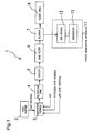
- Fig. 1 illustrates a biomass gasification power generation system 1 including a gas engine to which a scavenging operation method of the present invention is applicable.
- the biomass gasification power generation system 1 includes: a feed hopper 2 for feeding a woody biomass raw material such as sawdust; a gasification furnace 3 in which the biomass raw material is heated to generate pyrolysis gas; a retention tank 4 in which the pyrolysis gas generated is temporarily retained for removing tar and the like by decomposition; a cooler 5 in which the pyrolysis gas from which tar and the like is removed is cooled; a bag filter 6 for removing dust from the cooled pyrolysis gas; and a blower 7 for feeding the dust-removed pyrolysis gas to the gas engine 12 of a power generation apparatus 11 as a combustion gas.
- a feed hopper 2 for feeding a woody biomass raw material such as sawdust
- a gasification furnace 3 in which the biomass raw material is heated to generate pyrolysis gas
- the power generation apparatus 11 includes the gas engine 12 and a generator 13 connected to an output shaft of the gas engine 12.
- a flare stack 8 is also connected to the blower 7 for discharging pyrolysis gas when the power generation apparatus 11 is not operated.
- the gasification furnace 3 is supplied with air, furnace building for sealing, LPG for ignition, and the like, as well as the raw material described above.
- the biomass gasification power generation system 1 is configured to provide electricity using the generator 13, hot water heated with waste heat of exhaust gas of the engine 12, and so on.
- a dual-fuel engine power generation method is used for the power generation apparatus 11.
- Fig. 2 illustrates the gas engine 12 which is a 4-cycle engine disposed in the power generation apparatus 11 of Fig. 1 .
- the engine 12 includes a cylinder 21, a piston 22, a crankshaft 23, an intake valve 24, an intake path 25, an exhaust valve 26, an exhaust path 27, a spark plug 28, and a starter motor 29.
- a fuel gas supply device 30 is a mixer type device including: a venturi mixer 31 disposed in the intake path 25; a solenoid valve 33 for supplying fuel gas blown from the blower 7 to a regulator 32; and a fuel control valve 34 for supplying fuel gas stored in the regulator 32 to the venturi mixer 31, wherein a throttle valve 35 is disposed at the intake downstream side of the venturi mixer 31 for controlling the flow rate of a mixture gas of air and fuel gas.
- an engine speed sensor 36 is disposed at the crankshaft 23 for detecting the rotation speed of the crankshaft, that is, the engine speed of the engine.
- the spark plug 28, the solenoid valve 33, the fuel control valve 34, the throttle valve 35, and the engine speed sensor 36 are electrically connected to a controller (control unit) 40, wherein if an RPM detection signal is input from the engine speed sensor 36, the controller 40 at least sends an ignition instruction signal to the spark plug 28 and an opening/closing signal to the solenoid valve 33, and then opening degree instruction signals to the fuel control valve 34 and the throttle valve 35 for controlling the opening degrees thereof.
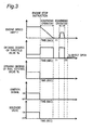
- Fig. 3 is a time chart illustrating a scavenging operation method of the present invention, in which horizontal axes represent time (sec), and vertical axes indicate, from top to bottom, change in engine speed, change in opening degree of throttle valve, change in opening degree of fuel control valve, ON/OFF of ignition signal, and ON/OFF of solenoid valve.
- the controller 40 closes the solenoid valve 33 and the fuel control valve 34 for stopping fuel gas supply to the inside of the cylinder 21. In addition, the controller 40 does not send an ignition instruction to the spark plug 28. Then, after the stop instruction, the engine speed of the engine 12 reduces (the engine 12 starts to idle). Along with this, the controller 40 opens the throttle valve 35 to a predetermined degree of opening or greater. As a result, since the engine 12 is idling, only air is supplied into the cylinder 21 from the throttle valve 35.
- the controller 40 closes the throttle valve 35.
- the engine 12 After a time period (T1) from the time point when the engine speed reaches zero and the throttle valve 35 is closed, the engine 12 is cranked by the starter motor 29 (the engine 12 is rotated), and at the same time the controller 40 opens the throttle valve 35 to the predetermined degree of opening or greater.
- the controller 40 closes the throttle valve 35.
- the controller 40 After a time period (T2) from the time point when the throttle valve 35 is closed after the engine 12 is cranked, the controller 40 opens the throttle valve 35 to a degree of opening smaller than the predetermined degree of opening.
- the spark plug 28 or the cylinder liner inside the cylinder 21 can be prevented from rusting or corroding more reliably.
- the predetermined degree of opening of the throttle valve 35 is full opening (100%).
- the degree of opening of the throttle valve 35 after cranking may be determined so that a gap can be formed between the throttle valve 35 and the intake path 25.
- the degree of opening of the throttle valve 35 after cranking may be several percents (%).
- Fig. 4 is a time chart illustrating a scavenging operation method according to another embodiment of the present invention, in which horizontal axes represent time (sec), and vertical axes indicate, from top to bottom, change in engine speed, change in opening degree of throttle valve, change in opening degree of fuel control valve, ON/OFF of ignition signal, and ON/OFF of solenoid valve.
- the current embodiment is the same as the first embodiment except for ON/OFF of an ignition signal. Therefore, detailed descriptions of the same parts as those of the first embodiment will be omitted.
- the controller 40 sends an ignition instruction to the spark plug 28 while the engine speed reduces and while the engine 12 is cranked by the starter motor 29.
- the throttle valve 35 is opened to perform a scavenging operation.
- a scavenging operation may be performed during one of the periods.
- the engine 12 may be cranked by the starter motor 29 for a longer time period to increase the amount of air passing through the cylinder 21 and thus to remove the large amount of moisture from the inside of the cylinder 21.
- Fig. 5 illustrates a gas engine 12 including an injector 37 as a fuel gas supply device 30, and a throttle valve 35 is disposed at the intake upstream side of the injector 37.
- the other mechanical structures are the same as those of the mixer type shown in Fig. 2 , and the same parts are denoted by the same reference numerals used in Fig. 2 .
- a scavenging operation method is carried out by controlling the injector 37 in the same way as the way of controlling the fuel control valve 34 shown in Fig. 2 . That is, if a stop instruction is input to stop the gas engine 12, a controller 40 closes the injector 37, and then other control procedures are performed as described above.
- the scavenging operation method of the present invention can be applied to a 2-cycle engine.
- a gas engine to which the scavenging operation method of the present invention is applicable can be used in various industrial equipment as well as in the power generation apparatus of the biomass gasification power generation system.
- Biomass gasification power generation system Feed hopper 3 Gasification furnace 4 Retention tank 5 Cooler 6 Bag filter 7 Blower 12 Gas engine 21 Cylinder 22 Piston 23 Crankshaft 24 Intake valve 25 Intake path 26 Exhaust valve 27 Exhaust path 28 Spark plug 29 Starter motor 30 Fuel gas supply device 31 Venturi mixer 32 Regulator 33 Solenoid valve 34 Fuel control valve 35 Throttle valve 36 Engine speed sensor 37 Injector 40 Controller (control unit)
Landscapes
- Engineering & Computer Science (AREA)
- Chemical & Material Sciences (AREA)
- Combustion & Propulsion (AREA)
- Mechanical Engineering (AREA)
- General Engineering & Computer Science (AREA)
- Chemical Kinetics & Catalysis (AREA)
- General Chemical & Material Sciences (AREA)
- Oil, Petroleum & Natural Gas (AREA)
- Combined Controls Of Internal Combustion Engines (AREA)
- Electrical Control Of Air Or Fuel Supplied To Internal-Combustion Engine (AREA)
- Output Control And Ontrol Of Special Type Engine (AREA)
- Control Of Throttle Valves Provided In The Intake System Or In The Exhaust System (AREA)
Abstract
Description
- The present invention relates to a scavenging operation method for a gas engine after an engine stop instruction, and more particularly, to a scavenging operation method suitable for a biomass gasification fuel gas engine after an engine stop instruction.
- A gas engine is started as follows. A starter motor is operated to crank the engine, and according to the cranking of the engine, fuel is supplied into a combustion chamber and a spark plug is operated to start the engine.
- However, if the engine fails to start, since the fuel/air ratio of a mixture gas remaining in the combustion chamber becomes too high, it is difficult to ignite the mixture gas, and the spark plug is wet by liquid fuel, thereby making it more difficult to start the engine again. As a countermeasure for such start failure, a scavenging operation is performed in the related art as is illustrated in
PTLs 1 and 2. In the scavenging operation, if such start failure occurs, the degree of opening of a throttle valve is set to a predetermined value or more, and cranking is carried out in a state where supply of fuel is stopped. In this way, unburned fuel remaining in the combustion chamber is discharged from a cylinder, and thus the next starting can be guaranteed more reliably. -
- [PTL 1]
JP 2000-265880 A - [PTL 2]
JP 10-331691 A - Recently, power generation systems are being developed, in which gas fuel obtained by thermally decomposing substances such as sawdust in a gasification furnace, gas fuel discharged from garbage disposal facilities, biomass gas fuel obtained from biological excrement or the like, or gas fuel gushing from reclaimed land is used to operate a gas engine and thus to operate a power generation apparatus using the gas engine.
- In the gas engine included in such a power generation system, a large amount of moisture or contaminants remains in a cylinder of the engine after the engine is stopped, and thus a spark plug or a cylinder liner may rust or corrode to decrease the durability of the engine.
- Therefore, the present invention is directed to prevent a spark plug or a cylinder liner from rusting or corroding by removing moisture or the like from a cylinder after an engine stop instruction.
- The present invention provides a scavenging operation method for a gas engine including: a fuel control valve that controls a supply amount of fuel gas; a throttle valve that controls a supply amount of a mixture gas of fuel gas and air; and a control unit, the scavenging operation method including: causing the control unit to close the fuel control valve in response to a stop instruction for stopping the gas engine; and while engine speed of the gas engine decreases after the stop instruction, causing the control unit to open the throttle valve to a predetermined degree of opening or greater.
- According to the above-described configuration, while the engine speed of the gas engine decreases after the stop instruction, since throttle valve is opened to the predetermined degree of opening or greater in a state where the fuel control valve is closed, only air is supplied from the throttle valve, and the air removes moisture from the inside of a cylinder. As a result, a spark plug or a cylinder liner inside the cylinder can be prevented from rusting or corroding.
- In addition, it may be preferable that the present invention has the following configurations.
- (1) The gas engine includes a spark plug to ignite the mixture gas in a cylinder, and the scavenging operation method includes causing the control unit to send an ignition instruction to the spark plug while the engine speed of the gas engine decreases after the stop instruction.
- (2) The gas engine includes a starter motor, and after the gas engine stops rotating, the scavenging operation method includes: causing the control unit to open the throttle valve to the predetermined degree of opening or greater while the control unit keeps the fuel control valve closed; and cranking the gas engine using the starter motor.
- (3) In the configuration (2), the gas engine includes a spark plug to ignite the mixture gas in a cylinder, and the scavenging operation method includes causing the control unit to send an ignition instruction to the spark plug while the gas engine is cranked by the starter motor.
- (4) In the configuration (2) or (3), the scavenging operation method includes causing the control unit to keep the throttle valve open after the gas engine is cranked by the starter motor.
- According to the configuration (1), fuel remaining around the spark plug can be burned by sending an ignition instruction to the spark plug, and thus the spark plug can be prevented from being stained.
- According to the configuration (2), even after the engine stops rotating, the engine can be cranked by the starter motor, and moisture can be removed from the inside of the cylinder with air supplied from the throttle valve. As a result, the spark plug or the cylinder liner inside the cylinder can be prevented from rusting or corroding more reliably.
- According to the configuration (3), since an ignition instruction is sent to the spark plug even while the engine is cranked by the starter motor, fuel remaining around the spark plug can be burned. As a result, the spark plug can be prevented from being stained more reliably.
- According to the configuration (4), since the throttle valve is opened even when the engine is not operated, sticking of the throttle valve can be prevented.
- Therefore, according to the present invention, the spark plug or the cylinder liner inside the cylinder can be prevented from rusting or corroding.
-
- [
Fig. 1 ]
Fig. 1 is a block diagram schematically showing a gasification power generation system including a gas engine for carrying out the present invention. - [
Fig. 2 ]
Fig. 2 is a configuration diagram showing the gas engine ofFig. 1 . - [
Fig. 3 ]
Fig. 3 is a time chart showing engine speed, opening degree of throttle valve, opening degree of fuel control valve, ignition signal, and operational state of solenoid valve according to a scavenging operation method of the present invention. - [
Fig. 4 ]
Fig. 4 is a time chart showing a scavenging operation method according to another embodiment of the present invention. - [
Fig. 5 ]
Fig. 5 is a configuration diagram of a gas engine including an injector as a fuel gas supply device. -
Fig. 1 illustrates a biomass gasificationpower generation system 1 including a gas engine to which a scavenging operation method of the present invention is applicable. The biomass gasificationpower generation system 1 includes: a feed hopper 2 for feeding a woody biomass raw material such as sawdust; a gasification furnace 3 in which the biomass raw material is heated to generate pyrolysis gas; aretention tank 4 in which the pyrolysis gas generated is temporarily retained for removing tar and the like by decomposition; acooler 5 in which the pyrolysis gas from which tar and the like is removed is cooled; abag filter 6 for removing dust from the cooled pyrolysis gas; and ablower 7 for feeding the dust-removed pyrolysis gas to thegas engine 12 of a power generation apparatus 11 as a combustion gas. The power generation apparatus 11 includes thegas engine 12 and agenerator 13 connected to an output shaft of thegas engine 12. Aflare stack 8 is also connected to theblower 7 for discharging pyrolysis gas when the power generation apparatus 11 is not operated. The gasification furnace 3 is supplied with air, furnace building for sealing, LPG for ignition, and the like, as well as the raw material described above. - The biomass gasification
power generation system 1 is configured to provide electricity using thegenerator 13, hot water heated with waste heat of exhaust gas of theengine 12, and so on. A dual-fuel engine power generation method is used for the power generation apparatus 11. -
Fig. 2 illustrates thegas engine 12 which is a 4-cycle engine disposed in the power generation apparatus 11 ofFig. 1 . As known in the related art, theengine 12 includes acylinder 21, apiston 22, acrankshaft 23, anintake valve 24, anintake path 25, anexhaust valve 26, anexhaust path 27, aspark plug 28, and astarter motor 29. A fuelgas supply device 30 is a mixer type device including: aventuri mixer 31 disposed in theintake path 25; asolenoid valve 33 for supplying fuel gas blown from theblower 7 to aregulator 32; and afuel control valve 34 for supplying fuel gas stored in theregulator 32 to theventuri mixer 31, wherein athrottle valve 35 is disposed at the intake downstream side of theventuri mixer 31 for controlling the flow rate of a mixture gas of air and fuel gas. In addition, anengine speed sensor 36 is disposed at thecrankshaft 23 for detecting the rotation speed of the crankshaft, that is, the engine speed of the engine. - The spark plug 28, the
solenoid valve 33, thefuel control valve 34, thethrottle valve 35, and theengine speed sensor 36 are electrically connected to a controller (control unit) 40, wherein if an RPM detection signal is input from theengine speed sensor 36, thecontroller 40 at least sends an ignition instruction signal to thespark plug 28 and an opening/closing signal to thesolenoid valve 33, and then opening degree instruction signals to thefuel control valve 34 and thethrottle valve 35 for controlling the opening degrees thereof. -
Fig. 3 is a time chart illustrating a scavenging operation method of the present invention, in which horizontal axes represent time (sec), and vertical axes indicate, from top to bottom, change in engine speed, change in opening degree of throttle valve, change in opening degree of fuel control valve, ON/OFF of ignition signal, and ON/OFF of solenoid valve. - If a stop instruction is input to stop the
engine 12, thecontroller 40 closes thesolenoid valve 33 and thefuel control valve 34 for stopping fuel gas supply to the inside of thecylinder 21. In addition, thecontroller 40 does not send an ignition instruction to thespark plug 28. Then, after the stop instruction, the engine speed of theengine 12 reduces (theengine 12 starts to idle). Along with this, thecontroller 40 opens thethrottle valve 35 to a predetermined degree of opening or greater. As a result, since theengine 12 is idling, only air is supplied into thecylinder 21 from thethrottle valve 35. - Thereafter, if the engine speed reaches zero, the
controller 40 closes thethrottle valve 35. - After a time period (T1) from the time point when the engine speed reaches zero and the
throttle valve 35 is closed, theengine 12 is cranked by the starter motor 29 (theengine 12 is rotated), and at the same time thecontroller 40 opens thethrottle valve 35 to the predetermined degree of opening or greater. - After the
engine 12 is cranked by the starter motor 29 (if the engine speed reaches zero), thecontroller 40 closes thethrottle valve 35. - After a time period (T2) from the time point when the
throttle valve 35 is closed after theengine 12 is cranked, thecontroller 40 opens thethrottle valve 35 to a degree of opening smaller than the predetermined degree of opening. - According to the scavenging operation method, the following effects can be attained.
- While the engine speed decreases after a stop instruction is input to stop the
engine 12, since thethrottle valve 35 is opened at a predetermined degree of opening or greater in a state where thesolenoid valve 33 and thefuel control valve 34 are closed, supply of fuel gas is stopped, and only air is supplied into thecylinder 21 from thethrottle valve 35 to remove moisture from thecylinder 21. As a result, thespark plug 28 or a cylinder liner inside thecylinder 21 can be prevented from rusting or corroding. - After the engine stops rotating, since the
engine 12 is cranked by thestarter motor 29 to remove moisture from the inside of thecylinder 21 with air supplied from thethrottle valve 35, thespark plug 28 or the cylinder liner inside thecylinder 21 can be prevented from rusting or corroding more reliably. - While the
engine 12 is not operated after theengine 12 is cranked by thestarter motor 29, since thethrottle valve 35 is opened, sticking of thethrottle valve 35 can be prevented. - It is preferable that the predetermined degree of opening of the
throttle valve 35 is full opening (100%). In addition, the degree of opening of thethrottle valve 35 after cranking may be determined so that a gap can be formed between thethrottle valve 35 and theintake path 25. For example, the degree of opening of thethrottle valve 35 after cranking may be several percents (%). -
Fig. 4 is a time chart illustrating a scavenging operation method according to another embodiment of the present invention, in which horizontal axes represent time (sec), and vertical axes indicate, from top to bottom, change in engine speed, change in opening degree of throttle valve, change in opening degree of fuel control valve, ON/OFF of ignition signal, and ON/OFF of solenoid valve. The current embodiment is the same as the first embodiment except for ON/OFF of an ignition signal. Therefore, detailed descriptions of the same parts as those of the first embodiment will be omitted. - In the current embodiment, after a stop instruction is input to stop the
engine 12, thecontroller 40 sends an ignition instruction to thespark plug 28 while the engine speed reduces and while theengine 12 is cranked by thestarter motor 29. - According to the current embodiment, since an ignition instruction is sent to the
spark plug 28 while the engine speed reduces and while theengine 12 is cranked, fuel remaining around thespark plug 28 can be burnt, and thus thespark plug 28 can be prevented from being stained. - In the first and second embodiments, during both the period when the engine speed reduces and the period when the
engine 12 is cranked, thethrottle valve 35 is opened to perform a scavenging operation. However, if a small amount of moisture remains in thecylinder 21, a scavenging operation may be performed during one of the periods. On the contrary, if a large amount of moisture remains in thecylinder 21, theengine 12 may be cranked by thestarter motor 29 for a longer time period to increase the amount of air passing through thecylinder 21 and thus to remove the large amount of moisture from the inside of thecylinder 21. -
Fig. 5 illustrates agas engine 12 including aninjector 37 as a fuelgas supply device 30, and athrottle valve 35 is disposed at the intake upstream side of theinjector 37. The other mechanical structures are the same as those of the mixer type shown inFig. 2 , and the same parts are denoted by the same reference numerals used inFig. 2 . - A scavenging operation method is carried out by controlling the
injector 37 in the same way as the way of controlling thefuel control valve 34 shown inFig. 2 . That is, if a stop instruction is input to stop thegas engine 12, acontroller 40 closes theinjector 37, and then other control procedures are performed as described above. - The scavenging operation method of the present invention can be applied to a 2-cycle engine.
- The present invention is not limited to the configurations of the above-described embodiments, but includes various modification examples that could be conceived of by those of ordinary skill in the art without departing from the scope of the present invention as defined in the claims.
- A gas engine to which the scavenging operation method of the present invention is applicable can be used in various industrial equipment as well as in the power generation apparatus of the biomass gasification power generation system.
-
1 Biomass gasification power generation system 2 Feed hopper 3 Gasification furnace 4 Retention tank 5 Cooler 6 Bag filter 7 Blower 12 Gas engine 21 Cylinder 22 Piston 23 Crankshaft 24 Intake valve 25 Intake path 26 Exhaust valve 27 Exhaust path 28 Spark plug 29 Starter motor 30 Fuel gas supply device 31 Venturi mixer 32 Regulator 33 Solenoid valve 34 Fuel control valve 35 Throttle valve 36 Engine speed sensor 37 Injector 40 Controller (control unit)
Claims (5)
- A scavenging operation method for a gas engine including: a fuel control valve that controls a supply amount of fuel gas; a throttle valve that controls a supply amount of a mixture gas of fuel gas and air; and a control unit, the scavenging operation method comprising:causing the control unit to close the fuel control valve in response to a stop instruction for stopping the gas engine; andwhile engine speed of the gas engine decreases after the stop instruction, causing the control unit to open the throttle valve to a predetermined degree of opening or greater.
- The scavenging operation method according to claim 1, wherein the gas engine includes a spark plug to ignite the mixture gas in a cylinder, and
the scavenging operation method comprises causing the control unit to send an ignition instruction to the spark plug while the engine speed of the gas engine decreases after the stop instruction. - The scavenging operation method according to claim 1 or 2, wherein the gas engine includes a starter motor, and
after the gas engine stops rotating, the scavenging operation method comprises: causing the control unit to open the throttle valve to the predetermined degree of opening or greater while the control unit keeps the fuel control valve closed; and cranking the gas engine using the starter motor. - The scavenging operation method according to claim 3, wherein the gas engine includes a spark plug to ignite the mixture gas in a cylinder, and
the scavenging operation method comprises causing the control unit to send an ignition instruction to the spark plug while the gas engine is cranked by the starter motor. - The scavenging operation method according to claim 3 or 4, comprising causing the control unit to keep the throttle valve open after the gas engine is cranked by the starter motor.
Applications Claiming Priority (2)
| Application Number | Priority Date | Filing Date | Title |
|---|---|---|---|
| JP2010176167A JP5577183B2 (en) | 2010-08-05 | 2010-08-05 | Gas engine scavenging operation method |
| PCT/JP2011/066899 WO2012017856A1 (en) | 2010-08-05 | 2011-07-26 | Scavenging operation method for gas engine |
Publications (3)
| Publication Number | Publication Date |
|---|---|
| EP2602459A1 true EP2602459A1 (en) | 2013-06-12 |
| EP2602459A4 EP2602459A4 (en) | 2018-04-04 |
| EP2602459B1 EP2602459B1 (en) | 2019-09-04 |
Family
ID=45559359
Family Applications (1)
| Application Number | Title | Priority Date | Filing Date |
|---|---|---|---|
| EP11814484.9A Active EP2602459B1 (en) | 2010-08-05 | 2011-07-26 | Scavenging operation method for gas engine |
Country Status (4)
| Country | Link |
|---|---|
| EP (1) | EP2602459B1 (en) |
| JP (1) | JP5577183B2 (en) |
| MY (1) | MY166252A (en) |
| WO (1) | WO2012017856A1 (en) |
Cited By (2)
| Publication number | Priority date | Publication date | Assignee | Title |
|---|---|---|---|---|
| EP2952713A1 (en) * | 2014-06-03 | 2015-12-09 | Yanmar Co., Ltd. | Biomass gas-fired engine |
| EP3492726A1 (en) * | 2017-11-29 | 2019-06-05 | Toyota Jidosha Kabushiki Kaisha | Vehicle control device |
Families Citing this family (8)
| Publication number | Priority date | Publication date | Assignee | Title |
|---|---|---|---|---|
| KR101738322B1 (en) | 2011-01-13 | 2017-05-19 | 닛본 덴끼 가부시끼가이샤 | Video encoding device, video decoding device, video encoding method, video decoding method, and recording medium |
| JP6318009B2 (en) * | 2014-06-03 | 2018-04-25 | ヤンマー株式会社 | Biomass gas exclusive firing engine |
| KR20220023469A (en) * | 2020-08-21 | 2022-03-02 | 엘지전자 주식회사 | Gas engine heat pump and method thereof |
| CN113153547B (en) * | 2021-05-07 | 2023-08-18 | 潍柴动力股份有限公司 | Gas engine scavenging method, device, equipment, vehicle and storage medium |
| CN113217208B (en) * | 2021-06-02 | 2022-06-17 | 一汽解放汽车有限公司 | Three-way catalytic converter protection method and device, vehicle and storage medium |
| US11767811B2 (en) | 2021-09-01 | 2023-09-26 | American CNG, LLC | Supplemental fuel system for compression-ignition engine |
| JP7822671B2 (en) * | 2021-12-02 | 2026-03-03 | ダイハツ工業株式会社 | Control device for internal combustion engine |
| JP2024119198A (en) * | 2023-02-22 | 2024-09-03 | 株式会社豊田自動織機 | Internal combustion engine |
Family Cites Families (17)
| Publication number | Priority date | Publication date | Assignee | Title |
|---|---|---|---|---|
| JPS58140474A (en) * | 1982-02-16 | 1983-08-20 | Nissan Motor Co Ltd | Control device for engine |
| JPH01280640A (en) * | 1988-04-30 | 1989-11-10 | Suzuki Motor Co Ltd | Throttle valve adhesion preventing method for gas engine mixer |
| JPH03242466A (en) * | 1990-02-19 | 1991-10-29 | Hitachi Ltd | Ignition control method of engine |
| JPH0450415A (en) * | 1990-06-19 | 1992-02-19 | Hino Motors Ltd | Scavenging method |
| JPH05321689A (en) * | 1992-05-22 | 1993-12-07 | Mazda Motor Corp | Method of scavenge of gaseous fuel engine and device therefor |
| JPH10331691A (en) | 1997-05-30 | 1998-12-15 | Fujitsu Ten Ltd | Fuel injection controller |
| DE59709866D1 (en) * | 1997-10-31 | 2003-05-22 | Swatch Group Man Services Ag B | Process for reducing the pollutant emissions of an internal combustion engine |
| JP3552575B2 (en) | 1999-03-11 | 2004-08-11 | トヨタ自動車株式会社 | Intake control device for internal combustion engine |
| US6761147B2 (en) * | 2000-10-18 | 2004-07-13 | Denso Corporation | Control apparatus and method for internal combustion engine |
| JP3721088B2 (en) * | 2001-03-01 | 2005-11-30 | 株式会社日立製作所 | Control device for hybrid vehicle |
| DE50209970D1 (en) * | 2002-05-14 | 2007-05-31 | Ford Global Tech Llc | Method for preparing the starting of an internal combustion engine |
| JP3997868B2 (en) * | 2002-09-17 | 2007-10-24 | トヨタ自動車株式会社 | Internal combustion engine having supercharging scavenging means |
| JP4452200B2 (en) * | 2005-02-25 | 2010-04-21 | 三菱重工業株式会社 | Gas engine with EGR system and method of operating the same |
| JP2008075589A (en) * | 2006-09-22 | 2008-04-03 | Nissan Motor Co Ltd | EGR gas scavenger for internal combustion engine |
| JP2008157127A (en) * | 2006-12-25 | 2008-07-10 | Hino Motors Ltd | Gas engine |
| JP2009002164A (en) * | 2007-06-19 | 2009-01-08 | Suzuki Motor Corp | Engine control device |
| JP4476317B2 (en) * | 2007-08-30 | 2010-06-09 | 三菱重工業株式会社 | Integrated control method and apparatus for gas engine |
-
2010
- 2010-08-05 JP JP2010176167A patent/JP5577183B2/en not_active Expired - Fee Related
-
2011
- 2011-07-26 MY MYPI2013700197A patent/MY166252A/en unknown
- 2011-07-26 EP EP11814484.9A patent/EP2602459B1/en active Active
- 2011-07-26 WO PCT/JP2011/066899 patent/WO2012017856A1/en not_active Ceased
Non-Patent Citations (1)
| Title |
|---|
| See references of WO2012017856A1 * |
Cited By (2)
| Publication number | Priority date | Publication date | Assignee | Title |
|---|---|---|---|---|
| EP2952713A1 (en) * | 2014-06-03 | 2015-12-09 | Yanmar Co., Ltd. | Biomass gas-fired engine |
| EP3492726A1 (en) * | 2017-11-29 | 2019-06-05 | Toyota Jidosha Kabushiki Kaisha | Vehicle control device |
Also Published As
| Publication number | Publication date |
|---|---|
| JP5577183B2 (en) | 2014-08-20 |
| JP2012036784A (en) | 2012-02-23 |
| WO2012017856A1 (en) | 2012-02-09 |
| MY166252A (en) | 2018-06-22 |
| EP2602459A4 (en) | 2018-04-04 |
| EP2602459B1 (en) | 2019-09-04 |
Similar Documents
| Publication | Publication Date | Title |
|---|---|---|
| EP2602459B1 (en) | Scavenging operation method for gas engine | |
| EP2980397B1 (en) | Starting device for gas internal combustion engine | |
| DK178072B1 (en) | A method of operating an internal combustion engine | |
| CN105332802A (en) | Method and device for preventing freezing of spark plug | |
| US6325044B1 (en) | Apparatus and method for suppressing diesel engine emissions | |
| WO2005066479A1 (en) | Apparatus and method for suppressing internal combustion ignition engine emissions | |
| JP2012017663A (en) | Gas engine starting control method | |
| KR20150108425A (en) | Method for cleaning a combustion chamber of an internal combustion engine, and internal combustion engine | |
| EP3255272A1 (en) | Biogas engine | |
| JP2004108153A (en) | Dual fuel engine | |
| EP2952713B1 (en) | Biomass gas-fired engine | |
| US20130174811A1 (en) | Fuel supply device for internal combustion engine | |
| CN101100956A (en) | Urban domestic garbage burning, gasification and generation device | |
| KR20100083455A (en) | Starting method and apparatus for bio gas generator | |
| JP2591309B2 (en) | Fuel vapor emission suppression device | |
| JP4070115B2 (en) | Control method of dual fuel engine | |
| CN107010047B (en) | The control device of vehicle | |
| KR102086185B1 (en) | Operating method for pressurized fluidized furnace system | |
| US9777692B2 (en) | Exhaust purge device for gas internal combustion engine | |
| KR101487014B1 (en) | Dual fuel engine system using biogas and control method thereof | |
| CN116291987A (en) | A heating system, method and engine for methanol fuel | |
| RU174028U1 (en) | GAS GENERATOR | |
| US12422422B2 (en) | Internal combustion engine with a generator and a carbon monoxide sensor | |
| JP4587936B2 (en) | ENGINE CONTROL DEVICE AND ENGINE CONTROL METHOD | |
| US20160146141A1 (en) | Method of starting an internal combustion engine operated with a fuel-air mixture |
Legal Events
| Date | Code | Title | Description |
|---|---|---|---|
| PUAI | Public reference made under article 153(3) epc to a published international application that has entered the european phase |
Free format text: ORIGINAL CODE: 0009012 |
|
| 17P | Request for examination filed |
Effective date: 20130220 |
|
| AK | Designated contracting states |
Kind code of ref document: A1 Designated state(s): AL AT BE BG CH CY CZ DE DK EE ES FI FR GB GR HR HU IE IS IT LI LT LU LV MC MK MT NL NO PL PT RO RS SE SI SK SM TR |
|
| DAX | Request for extension of the european patent (deleted) | ||
| RA4 | Supplementary search report drawn up and despatched (corrected) |
Effective date: 20180306 |
|
| RIC1 | Information provided on ipc code assigned before grant |
Ipc: F02D 41/00 20060101ALI20180227BHEP Ipc: F02D 43/00 20060101ALI20180227BHEP Ipc: F02D 45/00 20060101ALI20180227BHEP Ipc: F02D 17/00 20060101ALI20180227BHEP Ipc: F02D 41/04 20060101ALI20180227BHEP Ipc: F02D 19/02 20060101AFI20180227BHEP |
|
| GRAP | Despatch of communication of intention to grant a patent |
Free format text: ORIGINAL CODE: EPIDOSNIGR1 |
|
| STAA | Information on the status of an ep patent application or granted ep patent |
Free format text: STATUS: GRANT OF PATENT IS INTENDED |
|
| INTG | Intention to grant announced |
Effective date: 20190304 |
|
| GRAS | Grant fee paid |
Free format text: ORIGINAL CODE: EPIDOSNIGR3 |
|
| RAP1 | Party data changed (applicant data changed or rights of an application transferred) |
Owner name: YANMAR CO., LTD. |
|
| RIN1 | Information on inventor provided before grant (corrected) |
Inventor name: HAGIWARA, RYOICHI Inventor name: OTSUBO, HIROYUKI Inventor name: NAKAZONO, TORU |
|
| GRAA | (expected) grant |
Free format text: ORIGINAL CODE: 0009210 |
|
| STAA | Information on the status of an ep patent application or granted ep patent |
Free format text: STATUS: THE PATENT HAS BEEN GRANTED |
|
| AK | Designated contracting states |
Kind code of ref document: B1 Designated state(s): AL AT BE BG CH CY CZ DE DK EE ES FI FR GB GR HR HU IE IS IT LI LT LU LV MC MK MT NL NO PL PT RO RS SE SI SK SM TR |
|
| REG | Reference to a national code |
Ref country code: GB Ref legal event code: FG4D |
|
| REG | Reference to a national code |
Ref country code: CH Ref legal event code: EP |
|
| REG | Reference to a national code |
Ref country code: AT Ref legal event code: REF Ref document number: 1175666 Country of ref document: AT Kind code of ref document: T Effective date: 20190915 |
|
| REG | Reference to a national code |
Ref country code: DE Ref legal event code: R096 Ref document number: 602011061855 Country of ref document: DE |
|
| REG | Reference to a national code |
Ref country code: IE Ref legal event code: FG4D |
|
| REG | Reference to a national code |
Ref country code: NL Ref legal event code: MP Effective date: 20190904 |
|
| REG | Reference to a national code |
Ref country code: LT Ref legal event code: MG4D |
|
| PG25 | Lapsed in a contracting state [announced via postgrant information from national office to epo] |
Ref country code: BG Free format text: LAPSE BECAUSE OF FAILURE TO SUBMIT A TRANSLATION OF THE DESCRIPTION OR TO PAY THE FEE WITHIN THE PRESCRIBED TIME-LIMIT Effective date: 20191204 Ref country code: SE Free format text: LAPSE BECAUSE OF FAILURE TO SUBMIT A TRANSLATION OF THE DESCRIPTION OR TO PAY THE FEE WITHIN THE PRESCRIBED TIME-LIMIT Effective date: 20190904 Ref country code: NO Free format text: LAPSE BECAUSE OF FAILURE TO SUBMIT A TRANSLATION OF THE DESCRIPTION OR TO PAY THE FEE WITHIN THE PRESCRIBED TIME-LIMIT Effective date: 20191204 Ref country code: HR Free format text: LAPSE BECAUSE OF FAILURE TO SUBMIT A TRANSLATION OF THE DESCRIPTION OR TO PAY THE FEE WITHIN THE PRESCRIBED TIME-LIMIT Effective date: 20190904 Ref country code: LT Free format text: LAPSE BECAUSE OF FAILURE TO SUBMIT A TRANSLATION OF THE DESCRIPTION OR TO PAY THE FEE WITHIN THE PRESCRIBED TIME-LIMIT Effective date: 20190904 Ref country code: FI Free format text: LAPSE BECAUSE OF FAILURE TO SUBMIT A TRANSLATION OF THE DESCRIPTION OR TO PAY THE FEE WITHIN THE PRESCRIBED TIME-LIMIT Effective date: 20190904 |
|
| PG25 | Lapsed in a contracting state [announced via postgrant information from national office to epo] |
Ref country code: LV Free format text: LAPSE BECAUSE OF FAILURE TO SUBMIT A TRANSLATION OF THE DESCRIPTION OR TO PAY THE FEE WITHIN THE PRESCRIBED TIME-LIMIT Effective date: 20190904 Ref country code: ES Free format text: LAPSE BECAUSE OF FAILURE TO SUBMIT A TRANSLATION OF THE DESCRIPTION OR TO PAY THE FEE WITHIN THE PRESCRIBED TIME-LIMIT Effective date: 20190904 Ref country code: GR Free format text: LAPSE BECAUSE OF FAILURE TO SUBMIT A TRANSLATION OF THE DESCRIPTION OR TO PAY THE FEE WITHIN THE PRESCRIBED TIME-LIMIT Effective date: 20191205 Ref country code: RS Free format text: LAPSE BECAUSE OF FAILURE TO SUBMIT A TRANSLATION OF THE DESCRIPTION OR TO PAY THE FEE WITHIN THE PRESCRIBED TIME-LIMIT Effective date: 20190904 Ref country code: AL Free format text: LAPSE BECAUSE OF FAILURE TO SUBMIT A TRANSLATION OF THE DESCRIPTION OR TO PAY THE FEE WITHIN THE PRESCRIBED TIME-LIMIT Effective date: 20190904 |
|
| REG | Reference to a national code |
Ref country code: AT Ref legal event code: MK05 Ref document number: 1175666 Country of ref document: AT Kind code of ref document: T Effective date: 20190904 |
|
| PG25 | Lapsed in a contracting state [announced via postgrant information from national office to epo] |
Ref country code: NL Free format text: LAPSE BECAUSE OF FAILURE TO SUBMIT A TRANSLATION OF THE DESCRIPTION OR TO PAY THE FEE WITHIN THE PRESCRIBED TIME-LIMIT Effective date: 20190904 Ref country code: EE Free format text: LAPSE BECAUSE OF FAILURE TO SUBMIT A TRANSLATION OF THE DESCRIPTION OR TO PAY THE FEE WITHIN THE PRESCRIBED TIME-LIMIT Effective date: 20190904 Ref country code: AT Free format text: LAPSE BECAUSE OF FAILURE TO SUBMIT A TRANSLATION OF THE DESCRIPTION OR TO PAY THE FEE WITHIN THE PRESCRIBED TIME-LIMIT Effective date: 20190904 Ref country code: RO Free format text: LAPSE BECAUSE OF FAILURE TO SUBMIT A TRANSLATION OF THE DESCRIPTION OR TO PAY THE FEE WITHIN THE PRESCRIBED TIME-LIMIT Effective date: 20190904 Ref country code: PT Free format text: LAPSE BECAUSE OF FAILURE TO SUBMIT A TRANSLATION OF THE DESCRIPTION OR TO PAY THE FEE WITHIN THE PRESCRIBED TIME-LIMIT Effective date: 20200106 Ref country code: PL Free format text: LAPSE BECAUSE OF FAILURE TO SUBMIT A TRANSLATION OF THE DESCRIPTION OR TO PAY THE FEE WITHIN THE PRESCRIBED TIME-LIMIT Effective date: 20190904 |
|
| PG25 | Lapsed in a contracting state [announced via postgrant information from national office to epo] |
Ref country code: IS Free format text: LAPSE BECAUSE OF FAILURE TO SUBMIT A TRANSLATION OF THE DESCRIPTION OR TO PAY THE FEE WITHIN THE PRESCRIBED TIME-LIMIT Effective date: 20200224 Ref country code: SK Free format text: LAPSE BECAUSE OF FAILURE TO SUBMIT A TRANSLATION OF THE DESCRIPTION OR TO PAY THE FEE WITHIN THE PRESCRIBED TIME-LIMIT Effective date: 20190904 Ref country code: CZ Free format text: LAPSE BECAUSE OF FAILURE TO SUBMIT A TRANSLATION OF THE DESCRIPTION OR TO PAY THE FEE WITHIN THE PRESCRIBED TIME-LIMIT Effective date: 20190904 Ref country code: SM Free format text: LAPSE BECAUSE OF FAILURE TO SUBMIT A TRANSLATION OF THE DESCRIPTION OR TO PAY THE FEE WITHIN THE PRESCRIBED TIME-LIMIT Effective date: 20190904 |
|
| REG | Reference to a national code |
Ref country code: DE Ref legal event code: R097 Ref document number: 602011061855 Country of ref document: DE |
|
| PLBE | No opposition filed within time limit |
Free format text: ORIGINAL CODE: 0009261 |
|
| STAA | Information on the status of an ep patent application or granted ep patent |
Free format text: STATUS: NO OPPOSITION FILED WITHIN TIME LIMIT |
|
| PG2D | Information on lapse in contracting state deleted |
Ref country code: IS |
|
| PG25 | Lapsed in a contracting state [announced via postgrant information from national office to epo] |
Ref country code: DK Free format text: LAPSE BECAUSE OF FAILURE TO SUBMIT A TRANSLATION OF THE DESCRIPTION OR TO PAY THE FEE WITHIN THE PRESCRIBED TIME-LIMIT Effective date: 20190904 Ref country code: IS Free format text: LAPSE BECAUSE OF FAILURE TO SUBMIT A TRANSLATION OF THE DESCRIPTION OR TO PAY THE FEE WITHIN THE PRESCRIBED TIME-LIMIT Effective date: 20200105 |
|
| 26N | No opposition filed |
Effective date: 20200605 |
|
| PG25 | Lapsed in a contracting state [announced via postgrant information from national office to epo] |
Ref country code: SI Free format text: LAPSE BECAUSE OF FAILURE TO SUBMIT A TRANSLATION OF THE DESCRIPTION OR TO PAY THE FEE WITHIN THE PRESCRIBED TIME-LIMIT Effective date: 20190904 |
|
| REG | Reference to a national code |
Ref country code: DE Ref legal event code: R082 Ref document number: 602011061855 Country of ref document: DE Representative=s name: DOMPATENT VON KREISLER SELTING WERNER - PARTNE, DE Ref country code: DE Ref legal event code: R081 Ref document number: 602011061855 Country of ref document: DE Owner name: YANMAR POWER TECHNOLOGY CO., LTD., JP Free format text: FORMER OWNER: YANMAR CO., LTD., OSAKA, JP |
|
| PG25 | Lapsed in a contracting state [announced via postgrant information from national office to epo] |
Ref country code: MC Free format text: LAPSE BECAUSE OF FAILURE TO SUBMIT A TRANSLATION OF THE DESCRIPTION OR TO PAY THE FEE WITHIN THE PRESCRIBED TIME-LIMIT Effective date: 20190904 |
|
| REG | Reference to a national code |
Ref country code: CH Ref legal event code: PL |
|
| GBPC | Gb: european patent ceased through non-payment of renewal fee |
Effective date: 20200726 |
|
| REG | Reference to a national code |
Ref country code: BE Ref legal event code: MM Effective date: 20200731 |
|
| PG25 | Lapsed in a contracting state [announced via postgrant information from national office to epo] |
Ref country code: GB Free format text: LAPSE BECAUSE OF NON-PAYMENT OF DUE FEES Effective date: 20200726 Ref country code: FR Free format text: LAPSE BECAUSE OF NON-PAYMENT OF DUE FEES Effective date: 20200731 Ref country code: LU Free format text: LAPSE BECAUSE OF NON-PAYMENT OF DUE FEES Effective date: 20200726 Ref country code: LI Free format text: LAPSE BECAUSE OF NON-PAYMENT OF DUE FEES Effective date: 20200731 Ref country code: CH Free format text: LAPSE BECAUSE OF NON-PAYMENT OF DUE FEES Effective date: 20200731 |
|
| PG25 | Lapsed in a contracting state [announced via postgrant information from national office to epo] |
Ref country code: BE Free format text: LAPSE BECAUSE OF NON-PAYMENT OF DUE FEES Effective date: 20200731 |
|
| PG25 | Lapsed in a contracting state [announced via postgrant information from national office to epo] |
Ref country code: IE Free format text: LAPSE BECAUSE OF NON-PAYMENT OF DUE FEES Effective date: 20200726 |
|
| PG25 | Lapsed in a contracting state [announced via postgrant information from national office to epo] |
Ref country code: TR Free format text: LAPSE BECAUSE OF FAILURE TO SUBMIT A TRANSLATION OF THE DESCRIPTION OR TO PAY THE FEE WITHIN THE PRESCRIBED TIME-LIMIT Effective date: 20190904 Ref country code: MT Free format text: LAPSE BECAUSE OF FAILURE TO SUBMIT A TRANSLATION OF THE DESCRIPTION OR TO PAY THE FEE WITHIN THE PRESCRIBED TIME-LIMIT Effective date: 20190904 Ref country code: CY Free format text: LAPSE BECAUSE OF FAILURE TO SUBMIT A TRANSLATION OF THE DESCRIPTION OR TO PAY THE FEE WITHIN THE PRESCRIBED TIME-LIMIT Effective date: 20190904 |
|
| PG25 | Lapsed in a contracting state [announced via postgrant information from national office to epo] |
Ref country code: MK Free format text: LAPSE BECAUSE OF FAILURE TO SUBMIT A TRANSLATION OF THE DESCRIPTION OR TO PAY THE FEE WITHIN THE PRESCRIBED TIME-LIMIT Effective date: 20190904 |
|
| PGFP | Annual fee paid to national office [announced via postgrant information from national office to epo] |
Ref country code: DE Payment date: 20250722 Year of fee payment: 15 |
|
| PGFP | Annual fee paid to national office [announced via postgrant information from national office to epo] |
Ref country code: IT Payment date: 20250724 Year of fee payment: 15 |