EP2601912A1 - Reverse shoulder baseplate with alignment guide for glenosphere - Google Patents
Reverse shoulder baseplate with alignment guide for glenosphere Download PDFInfo
- Publication number
- EP2601912A1 EP2601912A1 EP12195588.4A EP12195588A EP2601912A1 EP 2601912 A1 EP2601912 A1 EP 2601912A1 EP 12195588 A EP12195588 A EP 12195588A EP 2601912 A1 EP2601912 A1 EP 2601912A1
- Authority
- EP
- European Patent Office
- Prior art keywords
- component
- glenosphere
- implant assembly
- baseplate
- circumferential
- Prior art date
- Legal status (The legal status is an assumption and is not a legal conclusion. Google has not performed a legal analysis and makes no representation as to the accuracy of the status listed.)
- Granted
Links
Images





Classifications
-
- A—HUMAN NECESSITIES
- A61—MEDICAL OR VETERINARY SCIENCE; HYGIENE
- A61F—FILTERS IMPLANTABLE INTO BLOOD VESSELS; PROSTHESES; DEVICES PROVIDING PATENCY TO, OR PREVENTING COLLAPSING OF, TUBULAR STRUCTURES OF THE BODY, e.g. STENTS; ORTHOPAEDIC, NURSING OR CONTRACEPTIVE DEVICES; FOMENTATION; TREATMENT OR PROTECTION OF EYES OR EARS; BANDAGES, DRESSINGS OR ABSORBENT PADS; FIRST-AID KITS
- A61F2/00—Filters implantable into blood vessels; Prostheses, i.e. artificial substitutes or replacements for parts of the body; Appliances for connecting them with the body; Devices providing patency to, or preventing collapsing of, tubular structures of the body, e.g. stents
- A61F2/02—Prostheses implantable into the body
- A61F2/30—Joints
- A61F2/40—Joints for shoulders
- A61F2/4081—Glenoid components, e.g. cups
-
- A—HUMAN NECESSITIES
- A61—MEDICAL OR VETERINARY SCIENCE; HYGIENE
- A61B—DIAGNOSIS; SURGERY; IDENTIFICATION
- A61B17/00—Surgical instruments, devices or methods
- A61B17/56—Surgical instruments or methods for treatment of bones or joints; Devices specially adapted therefor
- A61B17/58—Surgical instruments or methods for treatment of bones or joints; Devices specially adapted therefor for osteosynthesis, e.g. bone plates, screws or setting implements
- A61B17/68—Internal fixation devices, including fasteners and spinal fixators, even if a part thereof projects from the skin
- A61B17/80—Cortical plates, i.e. bone plates; Instruments for holding or positioning cortical plates, or for compressing bones attached to cortical plates
- A61B17/8052—Cortical plates, i.e. bone plates; Instruments for holding or positioning cortical plates, or for compressing bones attached to cortical plates immobilised relative to screws by interlocking form of the heads and plate holes, e.g. conical or threaded
-
- A—HUMAN NECESSITIES
- A61—MEDICAL OR VETERINARY SCIENCE; HYGIENE
- A61F—FILTERS IMPLANTABLE INTO BLOOD VESSELS; PROSTHESES; DEVICES PROVIDING PATENCY TO, OR PREVENTING COLLAPSING OF, TUBULAR STRUCTURES OF THE BODY, e.g. STENTS; ORTHOPAEDIC, NURSING OR CONTRACEPTIVE DEVICES; FOMENTATION; TREATMENT OR PROTECTION OF EYES OR EARS; BANDAGES, DRESSINGS OR ABSORBENT PADS; FIRST-AID KITS
- A61F2/00—Filters implantable into blood vessels; Prostheses, i.e. artificial substitutes or replacements for parts of the body; Appliances for connecting them with the body; Devices providing patency to, or preventing collapsing of, tubular structures of the body, e.g. stents
- A61F2/02—Prostheses implantable into the body
- A61F2/30—Joints
- A61F2002/30001—Additional features of subject-matter classified in A61F2/28, A61F2/30 and subgroups thereof
- A61F2002/30108—Shapes
- A61F2002/3011—Cross-sections or two-dimensional shapes
- A61F2002/30112—Rounded shapes, e.g. with rounded corners
- A61F2002/30113—Rounded shapes, e.g. with rounded corners circular
-
- A—HUMAN NECESSITIES
- A61—MEDICAL OR VETERINARY SCIENCE; HYGIENE
- A61F—FILTERS IMPLANTABLE INTO BLOOD VESSELS; PROSTHESES; DEVICES PROVIDING PATENCY TO, OR PREVENTING COLLAPSING OF, TUBULAR STRUCTURES OF THE BODY, e.g. STENTS; ORTHOPAEDIC, NURSING OR CONTRACEPTIVE DEVICES; FOMENTATION; TREATMENT OR PROTECTION OF EYES OR EARS; BANDAGES, DRESSINGS OR ABSORBENT PADS; FIRST-AID KITS
- A61F2/00—Filters implantable into blood vessels; Prostheses, i.e. artificial substitutes or replacements for parts of the body; Appliances for connecting them with the body; Devices providing patency to, or preventing collapsing of, tubular structures of the body, e.g. stents
- A61F2/02—Prostheses implantable into the body
- A61F2/30—Joints
- A61F2002/30001—Additional features of subject-matter classified in A61F2/28, A61F2/30 and subgroups thereof
- A61F2002/30108—Shapes
- A61F2002/30199—Three-dimensional shapes
- A61F2002/30224—Three-dimensional shapes cylindrical
-
- A—HUMAN NECESSITIES
- A61—MEDICAL OR VETERINARY SCIENCE; HYGIENE
- A61F—FILTERS IMPLANTABLE INTO BLOOD VESSELS; PROSTHESES; DEVICES PROVIDING PATENCY TO, OR PREVENTING COLLAPSING OF, TUBULAR STRUCTURES OF THE BODY, e.g. STENTS; ORTHOPAEDIC, NURSING OR CONTRACEPTIVE DEVICES; FOMENTATION; TREATMENT OR PROTECTION OF EYES OR EARS; BANDAGES, DRESSINGS OR ABSORBENT PADS; FIRST-AID KITS
- A61F2/00—Filters implantable into blood vessels; Prostheses, i.e. artificial substitutes or replacements for parts of the body; Appliances for connecting them with the body; Devices providing patency to, or preventing collapsing of, tubular structures of the body, e.g. stents
- A61F2/02—Prostheses implantable into the body
- A61F2/30—Joints
- A61F2002/30001—Additional features of subject-matter classified in A61F2/28, A61F2/30 and subgroups thereof
- A61F2002/30316—The prosthesis having different structural features at different locations within the same prosthesis; Connections between prosthetic parts; Special structural features of bone or joint prostheses not otherwise provided for
- A61F2002/30329—Connections or couplings between prosthetic parts, e.g. between modular parts; Connecting elements
- A61F2002/30331—Connections or couplings between prosthetic parts, e.g. between modular parts; Connecting elements made by longitudinally pushing a protrusion into a complementarily-shaped recess, e.g. held by friction fit
- A61F2002/30332—Conically- or frustoconically-shaped protrusion and recess
-
- A—HUMAN NECESSITIES
- A61—MEDICAL OR VETERINARY SCIENCE; HYGIENE
- A61F—FILTERS IMPLANTABLE INTO BLOOD VESSELS; PROSTHESES; DEVICES PROVIDING PATENCY TO, OR PREVENTING COLLAPSING OF, TUBULAR STRUCTURES OF THE BODY, e.g. STENTS; ORTHOPAEDIC, NURSING OR CONTRACEPTIVE DEVICES; FOMENTATION; TREATMENT OR PROTECTION OF EYES OR EARS; BANDAGES, DRESSINGS OR ABSORBENT PADS; FIRST-AID KITS
- A61F2/00—Filters implantable into blood vessels; Prostheses, i.e. artificial substitutes or replacements for parts of the body; Appliances for connecting them with the body; Devices providing patency to, or preventing collapsing of, tubular structures of the body, e.g. stents
- A61F2/02—Prostheses implantable into the body
- A61F2/30—Joints
- A61F2002/30001—Additional features of subject-matter classified in A61F2/28, A61F2/30 and subgroups thereof
- A61F2002/30316—The prosthesis having different structural features at different locations within the same prosthesis; Connections between prosthetic parts; Special structural features of bone or joint prostheses not otherwise provided for
- A61F2002/30329—Connections or couplings between prosthetic parts, e.g. between modular parts; Connecting elements
- A61F2002/30331—Connections or couplings between prosthetic parts, e.g. between modular parts; Connecting elements made by longitudinally pushing a protrusion into a complementarily-shaped recess, e.g. held by friction fit
- A61F2002/30332—Conically- or frustoconically-shaped protrusion and recess
- A61F2002/30336—Stepped cones, i.e. having discrete diameter changes
-
- A—HUMAN NECESSITIES
- A61—MEDICAL OR VETERINARY SCIENCE; HYGIENE
- A61F—FILTERS IMPLANTABLE INTO BLOOD VESSELS; PROSTHESES; DEVICES PROVIDING PATENCY TO, OR PREVENTING COLLAPSING OF, TUBULAR STRUCTURES OF THE BODY, e.g. STENTS; ORTHOPAEDIC, NURSING OR CONTRACEPTIVE DEVICES; FOMENTATION; TREATMENT OR PROTECTION OF EYES OR EARS; BANDAGES, DRESSINGS OR ABSORBENT PADS; FIRST-AID KITS
- A61F2/00—Filters implantable into blood vessels; Prostheses, i.e. artificial substitutes or replacements for parts of the body; Appliances for connecting them with the body; Devices providing patency to, or preventing collapsing of, tubular structures of the body, e.g. stents
- A61F2/02—Prostheses implantable into the body
- A61F2/30—Joints
- A61F2002/30001—Additional features of subject-matter classified in A61F2/28, A61F2/30 and subgroups thereof
- A61F2002/30316—The prosthesis having different structural features at different locations within the same prosthesis; Connections between prosthetic parts; Special structural features of bone or joint prostheses not otherwise provided for
- A61F2002/30329—Connections or couplings between prosthetic parts, e.g. between modular parts; Connecting elements
- A61F2002/30331—Connections or couplings between prosthetic parts, e.g. between modular parts; Connecting elements made by longitudinally pushing a protrusion into a complementarily-shaped recess, e.g. held by friction fit
- A61F2002/30354—Cylindrically-shaped protrusion and recess, e.g. cylinder of circular basis
-
- A—HUMAN NECESSITIES
- A61—MEDICAL OR VETERINARY SCIENCE; HYGIENE
- A61F—FILTERS IMPLANTABLE INTO BLOOD VESSELS; PROSTHESES; DEVICES PROVIDING PATENCY TO, OR PREVENTING COLLAPSING OF, TUBULAR STRUCTURES OF THE BODY, e.g. STENTS; ORTHOPAEDIC, NURSING OR CONTRACEPTIVE DEVICES; FOMENTATION; TREATMENT OR PROTECTION OF EYES OR EARS; BANDAGES, DRESSINGS OR ABSORBENT PADS; FIRST-AID KITS
- A61F2/00—Filters implantable into blood vessels; Prostheses, i.e. artificial substitutes or replacements for parts of the body; Appliances for connecting them with the body; Devices providing patency to, or preventing collapsing of, tubular structures of the body, e.g. stents
- A61F2/02—Prostheses implantable into the body
- A61F2/30—Joints
- A61F2002/30001—Additional features of subject-matter classified in A61F2/28, A61F2/30 and subgroups thereof
- A61F2002/30316—The prosthesis having different structural features at different locations within the same prosthesis; Connections between prosthetic parts; Special structural features of bone or joint prostheses not otherwise provided for
- A61F2002/30329—Connections or couplings between prosthetic parts, e.g. between modular parts; Connecting elements
- A61F2002/30331—Connections or couplings between prosthetic parts, e.g. between modular parts; Connecting elements made by longitudinally pushing a protrusion into a complementarily-shaped recess, e.g. held by friction fit
- A61F2002/30354—Cylindrically-shaped protrusion and recess, e.g. cylinder of circular basis
- A61F2002/30357—Stepped cylinders, i.e. having discrete diameter changes
-
- A—HUMAN NECESSITIES
- A61—MEDICAL OR VETERINARY SCIENCE; HYGIENE
- A61F—FILTERS IMPLANTABLE INTO BLOOD VESSELS; PROSTHESES; DEVICES PROVIDING PATENCY TO, OR PREVENTING COLLAPSING OF, TUBULAR STRUCTURES OF THE BODY, e.g. STENTS; ORTHOPAEDIC, NURSING OR CONTRACEPTIVE DEVICES; FOMENTATION; TREATMENT OR PROTECTION OF EYES OR EARS; BANDAGES, DRESSINGS OR ABSORBENT PADS; FIRST-AID KITS
- A61F2/00—Filters implantable into blood vessels; Prostheses, i.e. artificial substitutes or replacements for parts of the body; Appliances for connecting them with the body; Devices providing patency to, or preventing collapsing of, tubular structures of the body, e.g. stents
- A61F2/02—Prostheses implantable into the body
- A61F2/30—Joints
- A61F2002/30001—Additional features of subject-matter classified in A61F2/28, A61F2/30 and subgroups thereof
- A61F2002/30316—The prosthesis having different structural features at different locations within the same prosthesis; Connections between prosthetic parts; Special structural features of bone or joint prostheses not otherwise provided for
- A61F2002/30329—Connections or couplings between prosthetic parts, e.g. between modular parts; Connecting elements
- A61F2002/30433—Connections or couplings between prosthetic parts, e.g. between modular parts; Connecting elements using additional screws, bolts, dowels, rivets or washers e.g. connecting screws
-
- A—HUMAN NECESSITIES
- A61—MEDICAL OR VETERINARY SCIENCE; HYGIENE
- A61F—FILTERS IMPLANTABLE INTO BLOOD VESSELS; PROSTHESES; DEVICES PROVIDING PATENCY TO, OR PREVENTING COLLAPSING OF, TUBULAR STRUCTURES OF THE BODY, e.g. STENTS; ORTHOPAEDIC, NURSING OR CONTRACEPTIVE DEVICES; FOMENTATION; TREATMENT OR PROTECTION OF EYES OR EARS; BANDAGES, DRESSINGS OR ABSORBENT PADS; FIRST-AID KITS
- A61F2/00—Filters implantable into blood vessels; Prostheses, i.e. artificial substitutes or replacements for parts of the body; Appliances for connecting them with the body; Devices providing patency to, or preventing collapsing of, tubular structures of the body, e.g. stents
- A61F2/02—Prostheses implantable into the body
- A61F2/30—Joints
- A61F2002/30001—Additional features of subject-matter classified in A61F2/28, A61F2/30 and subgroups thereof
- A61F2002/30316—The prosthesis having different structural features at different locations within the same prosthesis; Connections between prosthetic parts; Special structural features of bone or joint prostheses not otherwise provided for
- A61F2002/30535—Special structural features of bone or joint prostheses not otherwise provided for
- A61F2002/30604—Special structural features of bone or joint prostheses not otherwise provided for modular
-
- A—HUMAN NECESSITIES
- A61—MEDICAL OR VETERINARY SCIENCE; HYGIENE
- A61F—FILTERS IMPLANTABLE INTO BLOOD VESSELS; PROSTHESES; DEVICES PROVIDING PATENCY TO, OR PREVENTING COLLAPSING OF, TUBULAR STRUCTURES OF THE BODY, e.g. STENTS; ORTHOPAEDIC, NURSING OR CONTRACEPTIVE DEVICES; FOMENTATION; TREATMENT OR PROTECTION OF EYES OR EARS; BANDAGES, DRESSINGS OR ABSORBENT PADS; FIRST-AID KITS
- A61F2/00—Filters implantable into blood vessels; Prostheses, i.e. artificial substitutes or replacements for parts of the body; Appliances for connecting them with the body; Devices providing patency to, or preventing collapsing of, tubular structures of the body, e.g. stents
- A61F2/02—Prostheses implantable into the body
- A61F2/30—Joints
- A61F2/30767—Special external or bone-contacting surface, e.g. coating for improving bone ingrowth
- A61F2/30771—Special external or bone-contacting surface, e.g. coating for improving bone ingrowth applied in original prostheses, e.g. holes or grooves
- A61F2002/30772—Apertures or holes, e.g. of circular cross section
- A61F2002/30784—Plurality of holes
-
- A—HUMAN NECESSITIES
- A61—MEDICAL OR VETERINARY SCIENCE; HYGIENE
- A61F—FILTERS IMPLANTABLE INTO BLOOD VESSELS; PROSTHESES; DEVICES PROVIDING PATENCY TO, OR PREVENTING COLLAPSING OF, TUBULAR STRUCTURES OF THE BODY, e.g. STENTS; ORTHOPAEDIC, NURSING OR CONTRACEPTIVE DEVICES; FOMENTATION; TREATMENT OR PROTECTION OF EYES OR EARS; BANDAGES, DRESSINGS OR ABSORBENT PADS; FIRST-AID KITS
- A61F2/00—Filters implantable into blood vessels; Prostheses, i.e. artificial substitutes or replacements for parts of the body; Appliances for connecting them with the body; Devices providing patency to, or preventing collapsing of, tubular structures of the body, e.g. stents
- A61F2/02—Prostheses implantable into the body
- A61F2/30—Joints
- A61F2/30767—Special external or bone-contacting surface, e.g. coating for improving bone ingrowth
- A61F2/30771—Special external or bone-contacting surface, e.g. coating for improving bone ingrowth applied in original prostheses, e.g. holes or grooves
- A61F2002/30772—Apertures or holes, e.g. of circular cross section
- A61F2002/30784—Plurality of holes
- A61F2002/30785—Plurality of holes parallel
-
- A—HUMAN NECESSITIES
- A61—MEDICAL OR VETERINARY SCIENCE; HYGIENE
- A61F—FILTERS IMPLANTABLE INTO BLOOD VESSELS; PROSTHESES; DEVICES PROVIDING PATENCY TO, OR PREVENTING COLLAPSING OF, TUBULAR STRUCTURES OF THE BODY, e.g. STENTS; ORTHOPAEDIC, NURSING OR CONTRACEPTIVE DEVICES; FOMENTATION; TREATMENT OR PROTECTION OF EYES OR EARS; BANDAGES, DRESSINGS OR ABSORBENT PADS; FIRST-AID KITS
- A61F2/00—Filters implantable into blood vessels; Prostheses, i.e. artificial substitutes or replacements for parts of the body; Appliances for connecting them with the body; Devices providing patency to, or preventing collapsing of, tubular structures of the body, e.g. stents
- A61F2/02—Prostheses implantable into the body
- A61F2/30—Joints
- A61F2/40—Joints for shoulders
- A61F2/4081—Glenoid components, e.g. cups
- A61F2002/4085—Glenoid components, e.g. cups having a convex shape, e.g. hemispherical heads
Definitions
- the present invention relates to an alignment guide for reverse shoulder arthroplasty (RSA), and in particular it relates to such a guide for aligning the engagement between a glenosphere and baseplate via a central screw engaged to the baseplate.
- RSA reverse shoulder arthroplasty
- RSA reverse shoulder systems
- the baseplate may be fastened to the glenoid cavity of the scapula by a plurality of screws and a glenosphere having a convex joint surface may be screwed into the baseplate using an axial threaded feature and/or taper locked to a periphery of the baseplate.
- the glenosphere may engage the baseplate solely via a taper connection.
- a compression fit is not preferable between the glenopshere and baseplate due to the potential need for separating the two components once engaged to one another.
- the glenosphere and baseplate may become separated after a certain length of time. This may cause the glenosphere to tilt with respect to the baseplate or in some cases even completely separate therefrom. In either situation, the baseplate and glenosphere become misaligned.
- Some systems include first fastening a central screw to a glenosphere and then guiding the connection between the baseplate and glenosphere via the central screw. Guiding the connection between the baseplate and glenosphere is generally an important consideration due to minimal access and visibility that the surgeon may have during a RSA procedure. Access to the baseplate is generally narrow making it relatively difficult for the surgeon to have the visibility needed to correctly align the engagement between a baseplate and glenosphere.
- One embodiment in accordance with a first aspect of the present invention is an implant assembly including first, second and third components.
- the first component is preferably a baseplate
- the second component is preferably a glenosphere
- the third component is preferably a central screw.
- First component of the implant assembly preferably includes a top surface, a bottom surface, a side surface connecting the top and bottom surfaces, and at least one borehole extending through the top and bottom surfaces.
- Second component of the implant assembly preferably includes first and second circumferential recesses, the first circumferential recess defining a tapered wall having a minimum diameter at a base of the tapered wall, the second circumferential recess defining a circumferential wall having a constant diameter, the constant diameter of the circumferential wall being less than the minimum diameter of the tapered wall, the first and second circumferential recesses being in communication with one another.
- Third component of the implant assembly preferably includes a head portion and a body portion, the third component configured to be received at least partially within the at least one borehole of the first component.
- At least a portion of the head portion of the third component extends outwardly from the top surface of the first component when the third component is engaged to the at least one borehole of the first component such that the head portion can be slip-fit into the second circumferential recess of the second component and into engagement with the circumferential wall thereof, thereby guiding the engagement of the side surface of the first component into the first circumferential recess and into engagement with the tapered wall of the second component.
- the top surface of the second component is substantially flat and the bottom surface is convex.
- the side surface of the first component is preferably tapered and forms a circumferential perimeter of the first component, the side surface having a central longitudinal axis.
- the implant assembly includes a plurality of baseplates having variable thicknesses connecting the top and bottom surfaces thereof.
- the at least one borehole of the first component has a central axis that is coaxial with the central longitudinal axis of the side surface of the first component.
- the implant assembly further comprises a plurality of boreholes extending through the top and bottom surfaces of the first component that are equally spaced around a perimeter of the top and bottom surfaces, the boreholes adapted to receive screws for fixing the first component to a glenoid cavity of a patient.
- Each of the plurality of boreholes preferably includes a ramp portion adapted to receive and engage a head of a fixation screw.
- Each of the plurality of boreholes can either be straight or angled from the top surface of the baseplate.
- the third component further includes a neck portion that is tapered and at least partially threaded, and the at least one borehole includes a threaded portion adapted to engage the at least partially threaded portion of the third component.
- the head portion of the third component has a circumferential side surface and at least a portion of the body portion of the third component is threaded.
- the second component has a semispherical convex outer surface and the second component has a bore hole through an apex portion thereof.
- the borehole through the apex portion of the second component is preferably at least partially threaded.
- the tapered wall and the circumferential wall of the second component each have a longitudinal axis therethrough, the longitudinal axes being coaxial.
- the central axis of the at least one borehole is coaxial with the longitudinal axes of the tapered wall and the circumferential wall.
- One embodiment in accordance with a second aspect of the present invention is an implant assembly including first, second and third components.
- the first component preferably has a top surface, a bottom surface, a side surface connecting the top and bottom surfaces, and at least one borehole extending through the top and bottom surfaces, the distance between the top surface and bottom surface defining a first height.
- the second component preferably has first and second circumferential recesses, the first circumferential recess defining a tapered wall having a second height substantially equal to the first height, the second circumferential recess defining a circumferential wall having a third height greater than the second height of the tapered wall, the first and second circumferential recesses being in communication with one another.
- the third component has a head portion and a body portion, the third component configured to be received at least partially within the at least one borehole of the first component.
- the third component when engaged to the at least one borehole of the first component the head portion thereof extends outwardly from the top surface of the first component in an amount substantially equal to the third height, and at least a portion of the head portion of the third component is located within the second circumferential recess of the second component and is in engagement with the circumferential wall when at least a portion of the side surface of the first component is located within the first circumferential recess and is in engagement with the tapered wall of the second component.
- the top surface of the second component is substantially flat and the bottom surface is convex.
- the side surface of the first component is preferably tapered and forms a circumferential perimeter of the first component, the side surface having a central longitudinal axis.
- the implant assembly includes a plurality of baseplates having variable thicknesses connecting the top and bottom surfaces thereof.
- the at least one borehole of the first component has a central axis that is coaxial with the central longitudinal axis of the side surface of the first component.
- the implant assembly further comprises a plurality of boreholes extending through the top and bottom surfaces of the first component that are equally spaced around a perimeter of the top and bottom surfaces, the boreholes adapted to receive screws for fixing the first component to a glenoid cavity of a patient.
- Each of the plurality of boreholes preferably includes a ramp portion adapted to receive and engage a head of a fixation screw.
- Each of the plurality of boreholes can either be straight or angled from the top surface of the baseplate.
- the third component further includes a neck portion that is tapered and at least partially threaded, and the at least one borehole includes a threaded portion adapted to engage the at least partially threaded portion of the third component.
- the head portion of the third component has a circumferential side surface and at least a portion of the body portion of the third component is threaded.
- the second component has a semispherical convex outer surface and the second component has a bore hole through an apex portion thereof.
- the borehole through the apex portion of the second component is preferably at least partially threaded.
- the tapered wall and the circumferential wall of the second component each have a longitudinal axis therethrough, the longitudinal axes being coaxial.
- the central axis of the at least one borehole is coaxial with the longitudinal axes of the tapered wall and the circumferential wall.
- FIG. 1 is an exploded view of an implant system showing a two-piece construct prior to assembly with a glenosphere.
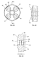
- FIG. 2A is a front view of one embodiment of a baseplate of the present invention.
- FIG. 2B is a cross-sectional side view taken along line A-A of the baseplate shown in FIG. 2A .
- FIG. 2C is an alternate side view of the baseplate shown in FIG. 2A .
- FIG. 3A is a back view of one embodiment of a glenosphere of the present invention.
- FIG. 3B is a cross-sectional side view taken along line B-B of the glenosphere shown in FIG. 3A .
- FIG. 3C is an alternate side view of the glenosphere shown in FIG. 3A .
- FIG. 4A is a perspective view of an alternate embodiment of a glenosphere of the present invention.
- FIG. 4B is a front view of the glenosphere shown in FIG. 4A .
- FIG. 4C is a cross-sectional side view taken along line C-C of the glenosphere shown in FIG. 4B .
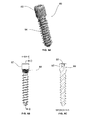
- FIG. 5A is a perspective view of one embodiment of a central screw of the present invention.
- FIG. 5B is a side plan view of the central screw shown in FIG. 5A .
- FIG. 5C is a cross-sectional side view taken along line D-D of the central screw shown in FIG. 5B .
- FIG. 6A is a perspective view of one embodiment of a two-piece construct of the present invention including an assembled baseplate and central screw.
- FIG. 6B is a top view of the two-piece construct shown in FIG. 6A .
- FIG. 6C is a side view of the two-piece construct shown in FIG. 6A .
- FIG. 7A is a perspective view of one embodiment of an implant assembly of the present invention showing a two-piece construct assembled to a glenosphere.
- FIG. 7B is a bottom view of the implant assembly shown in FIG. 7A .
- FIG. 7C is a side view of the implant assembly shown in FIG. 7A .
- FIG. 7D is a cross-sectional view taken along line E-E of the implant assembly shown in FIG. 7C .
- FIG. 8A is a cross-sectional view of a two-piece construct being assembled to a glenosphere.
- FIG. 8B is a cross-sectional view of the two-piece construct and glenosphere shown in FIG. 8A in an almost fully assembled position.
- proximal means closer to the heart and the term “distal” means more distant from the heart.
- distal means more distant from the heart.
- inferior means lower or bottom and the term “superior” means upper or top.
- anterior means towards the front part of the body or the face and the term “posterior” means toward the back of the body.
- medial means toward the midline of the body and the term “lateral” means away from the midline of the body.
- implant assembly 10 includes a first component or baseplate 20, a second component or glenosphere 50, and a third component or central screw 80.
- Baseplate 20 includes a bottom surface 22, a top surface 24, and a tapered side surface 26 connecting the bottom and top surfaces, the side surface 26 defining a height H1 and a having a minimum diameter D1 defined by a perimeter of top surface 24.
- a central bore hole 28 extends through bottom and top surfaces 22, 24, the central bore hole 28 having a longitudinal axis 30.
- bore hole 28 preferably includes a first diameter 32 and a second diameter 34 with the first diameter being larger than the second diameter.
- An intermediate portion 36 preferably separates first and second diameters 32, 34, the intermediate portion formed preferably as a singular thread projecting outwardly from a wall 38 of first diameter 32 of central bore hole 28.
- Bottom surface 22 of baseplate 20 is generally convex, while top surface 24 is generally flat. Disposed around and adjacent a perimeter or circumference 40 formed by side surface 26 of baseplate 20 are a plurality of screw receiving apertures 42. While baseplate 20 as shown in FIG. 2A , includes four screw receiving apertures 42, baseplate 20 may include less or more than four screw receiving apertures 42. As shown in FIG. 2A , apertures 42 moving in a clockwise direction include a longitudinal axis 41, 43, 45, or 47, respectively. Longitudinal axes 41, 43, 45 and 47 are preferably angled from longitudinal axis 30 between 15° and 75° as shown in FIG. 2C , for example.
- Longitudinal axes 41, 43, 45 and 47 may each be angled from longitudinal axis 30 that same amount of degrees or each may be angled from longitudinal axis 30 a different amount of degrees. In some embodiments, longitudinal axes 41, 43, 45 and 47 may be parallel to longitudinal axis 30 of bore hole 28.
- Glenosphere 50 includes a hemispherical or semispherical outer surface 52 having a perimeter 54 forming an outer diameter of a bottom surface 56.
- a first circumferential recess 58 having a depth DP1 slightly larger than height H1 of baseplate 20.
- depth DP1 may be substantially equivalent to height H1.
- First circumferential recess 58 defines a tapered wall 59 having a maximum diameter defining an outer perimeter 57 and a minimum diameter defining a first base portion 60 of the tapered wall.
- First circumferential recess 58 terminates at first base portion 60 of tapered wall 59.
- Second circumferential recess 62 defines a circumferential wall 61 having a constant diameter. Second circumferential recess 62 terminates at a base portion of circumferential wall 61 at a second base portion 64.
- the constant diameter of the circumferential wall 61 is preferably less than the minimum diameter of tapered wall 59.
- the first and second circumferential recesses 58 and 62 are in communication with one another.
- First circumferential recess includes a longitudinal axis 63 and second circumferential recess includes a longitudinal axis 65, the longitudinal axes 63, 65 of first and second circumferential recesses are coaxial. In other embodiments, longitudinal axes 63 and 65 may be offset from one another.
- Threaded bore 70 located at a polar or apex portion of glenosphere 50 is a threaded bore 70.
- Threaded bore 70 is in communication with first and second circumferential recesses 58 and 62.
- threaded bore 70 is a recess formed in outer surface 52 and is not in communication with either first or second circumferential recess 58 and 62.
- bore 70 is only partially threaded about a length thereof.
- FIGS.4A-4C there is shown another embodiment of glenosphere 50 of the present invention denoted as 50'.
- Glenosphere 50' includes all of the same features as glenosphere 50 except that the first and second circumferential recesses 58', 62' are offset from threaded bore 70' of glenosphere 50'.
- First circumferential recess 58' includes a longitudinal axis 63' and second circumferential recess 62' includes a longitudinal axis 65', the longitudinal axes 63', 65' of first and second circumferential recesses are coaxial.
- Glenosphere 50' includes a hemispherical or semispherical outer surface 52' having a perimeter 54' forming an outer diameter of a bottom surface 56'.
- Perimeter 54' includes a longitudinal axis 67' that is offset from longitudinal axes 63', 65' of first and second circumferential recesses 58', 62'.
- Central screw 80 includes a head portion 82, a body portion 84, a neck portion 86 and a longitudinal axis 90.
- Head portion 82 includes a circumferential side surface 83 defining a perimeter with a diameter D4.
- Body portion 84 of central screw 80 is preferably threaded.
- Neck portion 86 is preferably tapered and threaded.
- Central screw 80 further includes an engagement portion 88 for receiving an adjustment tool such as a screwdriver, for example.
- FIGS. 6A-6C there is shown one embodiment of a two-piece construct 100 including an assembled baseplate 20 and central screw 80.
- a portion of head portion 82 of central screw 80 projects outwardly from outer surface 24 of baseplate 20 a height H2.
- the height H2 may vary depending on the configuration of first and second circumferential recesses 58 and 62 of glenosphere 50, namely depths DP1 and DP2, respectively.
- implant assembly 10 with baseplate 20, glenosphere 50, and central screw 80 all being assembled together.
- the alignment guide of implant assembly 10 serves to enable a more efficient and reproducible alignment between glenosphere 50 and baseplate 20 during RSA.
- glenosphere 50 may be coupled thereto. It is important for the alignment of glenosphere 50 to be accurate on the baseplate 20. In other words longitudinal axis 30 of baseplate 20 and longitudinal axis 63 of glenosphere should be coaxial when implant assembly 10 is in an assembled position.
- the diameter D4 of head portion 82 of central screw 80 is preferably 8mm, but may be as little as 2mm and as much as 14mm, for example.
- head portion 82 of central 80 preferably protrudes from top surface 24 of baseplate 20 approximately 5mm.
- Second circumferential recess 62 of glenosphere 50 has a diameter of approximately 9mm (just slightly more than the diameter of head portion 82 of central screw 80) and a depth of 5.4mm (just slightly more than the amount head portion 82 of central screw 80 protrudes from top surface 24 of baseplate 20).
- Implant assembly 10 provides a surgeon or other operating room personnel with improved tactile feel and axial alignment when introducing glenosphere 50 onto baseplate 20 during final implantation. Reduction of surgery time is preferably a benefit attributable to implant assembly 10, which also has the potential to reduce the amount of time a surgeon needs to implant this device with a one-step procedure strategy.
- One aspect of the present invention is the assembly of glenosphere 50 with a two-piece construct 100, namely assembled central screw 80 and baseplate 20.
- a holding instrument (not shown) can be secured to bore 70 in order to aid the assembly of glenosphere 50 with two-piece construct 100.
- Alignment between baseplate 20 of two-piece construct 100 and glenosphere 50 is first introduced by the peripheral external taper of perimeter 26 of baseplate 20 and first internal bore 58 of glenosphere 50 as shown in FIG. 8A .
- At least a portion of head portion 82 of central screw 80 is located within pilot bore 62 prior to engagement between external taper 26 of baseplate 20 and tapered wall 59 of glenosphere 50 as shown in FIG. 8B .
- Pilot diameter D4 of head 82 of central screw 80 is configured to be accepted by pilot bore 62 with diameter D3 of glenosphere 50 in a slip-fit manner.
- the dimensions of head portion 82 of central screw and pilot bore 62 of glenosphere 50 aids in preventing glenosphere 50 from cantilevering out of its intended assembled position when external taper 26 of baseplate 20 is engaged to tapered wall 59 of glenosphere 50.
Landscapes
- Health & Medical Sciences (AREA)
- Orthopedic Medicine & Surgery (AREA)
- Cardiology (AREA)
- Oral & Maxillofacial Surgery (AREA)
- Transplantation (AREA)
- Engineering & Computer Science (AREA)
- Biomedical Technology (AREA)
- Heart & Thoracic Surgery (AREA)
- Vascular Medicine (AREA)
- Life Sciences & Earth Sciences (AREA)
- Animal Behavior & Ethology (AREA)
- General Health & Medical Sciences (AREA)
- Public Health (AREA)
- Veterinary Medicine (AREA)
- Prostheses (AREA)
Abstract
Description
- The present invention relates to an alignment guide for reverse shoulder arthroplasty (RSA), and in particular it relates to such a guide for aligning the engagement between a glenosphere and baseplate via a central screw engaged to the baseplate.
- Many existing reverse shoulder systems (RSA) require a baseplate and a glenosphere. These systems generally differ from one another in how the baseplate is fastened to the glenoid cavity and how the glenosphere becomes engaged to the baseplate. In some systems, the baseplate may be fastened to the glenoid cavity of the scapula by a plurality of screws and a glenosphere having a convex joint surface may be screwed into the baseplate using an axial threaded feature and/or taper locked to a periphery of the baseplate. In other systems, the glenosphere may engage the baseplate solely via a taper connection. Generally, a compression fit is not preferable between the glenopshere and baseplate due to the potential need for separating the two components once engaged to one another.
- In cases where the glenosphere becomes engaged to the baseplate through either a threaded or taper connection, the glenosphere and baseplate may become separated after a certain length of time. This may cause the glenosphere to tilt with respect to the baseplate or in some cases even completely separate therefrom. In either situation, the baseplate and glenosphere become misaligned.
- Some systems include first fastening a central screw to a glenosphere and then guiding the connection between the baseplate and glenosphere via the central screw. Guiding the connection between the baseplate and glenosphere is generally an important consideration due to minimal access and visibility that the surgeon may have during a RSA procedure. Access to the baseplate is generally narrow making it relatively difficult for the surgeon to have the visibility needed to correctly align the engagement between a baseplate and glenosphere.
- One embodiment in accordance with a first aspect of the present invention is an implant assembly including first, second and third components. The first component is preferably a baseplate, the second component is preferably a glenosphere, and the third component is preferably a central screw. First component of the implant assembly preferably includes a top surface, a bottom surface, a side surface connecting the top and bottom surfaces, and at least one borehole extending through the top and bottom surfaces. Second component of the implant assembly preferably includes first and second circumferential recesses, the first circumferential recess defining a tapered wall having a minimum diameter at a base of the tapered wall, the second circumferential recess defining a circumferential wall having a constant diameter, the constant diameter of the circumferential wall being less than the minimum diameter of the tapered wall, the first and second circumferential recesses being in communication with one another. Third component of the implant assembly preferably includes a head portion and a body portion, the third component configured to be received at least partially within the at least one borehole of the first component. At least a portion of the head portion of the third component extends outwardly from the top surface of the first component when the third component is engaged to the at least one borehole of the first component such that the head portion can be slip-fit into the second circumferential recess of the second component and into engagement with the circumferential wall thereof, thereby guiding the engagement of the side surface of the first component into the first circumferential recess and into engagement with the tapered wall of the second component.
- In another embodiment of the first aspect of the present invention the top surface of the second component is substantially flat and the bottom surface is convex. The side surface of the first component is preferably tapered and forms a circumferential perimeter of the first component, the side surface having a central longitudinal axis. In some embodiments, the implant assembly includes a plurality of baseplates having variable thicknesses connecting the top and bottom surfaces thereof.
- In yet another embodiment of the first aspect of the present invention the at least one borehole of the first component has a central axis that is coaxial with the central longitudinal axis of the side surface of the first component.
- In yet still another embodiment of the first aspect of the present invention the implant assembly further comprises a plurality of boreholes extending through the top and bottom surfaces of the first component that are equally spaced around a perimeter of the top and bottom surfaces, the boreholes adapted to receive screws for fixing the first component to a glenoid cavity of a patient. Each of the plurality of boreholes preferably includes a ramp portion adapted to receive and engage a head of a fixation screw. Each of the plurality of boreholes can either be straight or angled from the top surface of the baseplate.
- In still yet another embodiment of the first aspect of the present invention the third component further includes a neck portion that is tapered and at least partially threaded, and the at least one borehole includes a threaded portion adapted to engage the at least partially threaded portion of the third component. Preferably, the head portion of the third component has a circumferential side surface and at least a portion of the body portion of the third component is threaded.
- In still yet another embodiment of the first aspect of the present invention the second component has a semispherical convex outer surface and the second component has a bore hole through an apex portion thereof. The borehole through the apex portion of the second component is preferably at least partially threaded.
- In still yet another embodiment of the first aspect of the present invention the tapered wall and the circumferential wall of the second component each have a longitudinal axis therethrough, the longitudinal axes being coaxial. Preferably, when the first component is engaged to the second component, the central axis of the at least one borehole is coaxial with the longitudinal axes of the tapered wall and the circumferential wall.
- One embodiment in accordance with a second aspect of the present invention is an implant assembly including first, second and third components. The first component preferably has a top surface, a bottom surface, a side surface connecting the top and bottom surfaces, and at least one borehole extending through the top and bottom surfaces, the distance between the top surface and bottom surface defining a first height. The second component preferably has first and second circumferential recesses, the first circumferential recess defining a tapered wall having a second height substantially equal to the first height, the second circumferential recess defining a circumferential wall having a third height greater than the second height of the tapered wall, the first and second circumferential recesses being in communication with one another. The third component has a head portion and a body portion, the third component configured to be received at least partially within the at least one borehole of the first component. The third component when engaged to the at least one borehole of the first component the head portion thereof extends outwardly from the top surface of the first component in an amount substantially equal to the third height, and at least a portion of the head portion of the third component is located within the second circumferential recess of the second component and is in engagement with the circumferential wall when at least a portion of the side surface of the first component is located within the first circumferential recess and is in engagement with the tapered wall of the second component.
- In another embodiment of the second aspect of the present invention the top surface of the second component is substantially flat and the bottom surface is convex. The side surface of the first component is preferably tapered and forms a circumferential perimeter of the first component, the side surface having a central longitudinal axis. In some embodiments, the implant assembly includes a plurality of baseplates having variable thicknesses connecting the top and bottom surfaces thereof.
- In yet another embodiment of the second aspect of the present invention the at least one borehole of the first component has a central axis that is coaxial with the central longitudinal axis of the side surface of the first component.
- In yet still another embodiment of the second aspect of the present invention the implant assembly further comprises a plurality of boreholes extending through the top and bottom surfaces of the first component that are equally spaced around a perimeter of the top and bottom surfaces, the boreholes adapted to receive screws for fixing the first component to a glenoid cavity of a patient. Each of the plurality of boreholes preferably includes a ramp portion adapted to receive and engage a head of a fixation screw. Each of the plurality of boreholes can either be straight or angled from the top surface of the baseplate.
- In still yet another embodiment of the second aspect of the present invention the third component further includes a neck portion that is tapered and at least partially threaded, and the at least one borehole includes a threaded portion adapted to engage the at least partially threaded portion of the third component. Preferably, the head portion of the third component has a circumferential side surface and at least a portion of the body portion of the third component is threaded.
- In still yet another embodiment of the second aspect of the present invention the second component has a semispherical convex outer surface and the second component has a bore hole through an apex portion thereof. The borehole through the apex portion of the second component is preferably at least partially threaded.
- In still yet another embodiment of the second aspect of the present invention the tapered wall and the circumferential wall of the second component each have a longitudinal axis therethrough, the longitudinal axes being coaxial. Preferably, when the first component is engaged to the second component, the central axis of the at least one borehole is coaxial with the longitudinal axes of the tapered wall and the circumferential wall.
- A more complete appreciation of the subject matter of the present invention and the various advantages thereof can be realized by reference to the following detailed description in which reference is made to the accompanying drawings in which:
-
FIG. 1 is an exploded view of an implant system showing a two-piece construct prior to assembly with a glenosphere. -
FIG. 2A is a front view of one embodiment of a baseplate of the present invention. -
FIG. 2B is a cross-sectional side view taken along line A-A of the baseplate shown inFIG. 2A . -
FIG. 2C is an alternate side view of the baseplate shown inFIG. 2A . -
FIG. 3A is a back view of one embodiment of a glenosphere of the present invention. -
FIG. 3B is a cross-sectional side view taken along line B-B of the glenosphere shown inFIG. 3A . -
FIG. 3C is an alternate side view of the glenosphere shown inFIG. 3A . -
FIG. 4A is a perspective view of an alternate embodiment of a glenosphere of the present invention. -
FIG. 4B is a front view of the glenosphere shown inFIG. 4A . -
FIG. 4C is a cross-sectional side view taken along line C-C of the glenosphere shown inFIG. 4B . -
FIG. 5A is a perspective view of one embodiment of a central screw of the present invention. -
FIG. 5B is a side plan view of the central screw shown inFIG. 5A . -
FIG. 5C is a cross-sectional side view taken along line D-D of the central screw shown inFIG. 5B . -
FIG. 6A is a perspective view of one embodiment of a two-piece construct of the present invention including an assembled baseplate and central screw. -
FIG. 6B is a top view of the two-piece construct shown inFIG. 6A . -
FIG. 6C is a side view of the two-piece construct shown inFIG. 6A . -
FIG. 7A is a perspective view of one embodiment of an implant assembly of the present invention showing a two-piece construct assembled to a glenosphere. -
FIG. 7B is a bottom view of the implant assembly shown inFIG. 7A . -
FIG. 7C is a side view of the implant assembly shown inFIG. 7A . -
FIG. 7D is a cross-sectional view taken along line E-E of the implant assembly shown inFIG. 7C . -
FIG. 8A is a cross-sectional view of a two-piece construct being assembled to a glenosphere. -
FIG. 8B is a cross-sectional view of the two-piece construct and glenosphere shown inFIG. 8A in an almost fully assembled position. - As used herein, when referring to bones or other parts of the body, the term "proximal" means closer to the heart and the term "distal" means more distant from the heart. The term "inferior" means lower or bottom and the term "superior" means upper or top. The term "anterior" means towards the front part of the body or the face and the term "posterior" means toward the back of the body. The term "medial" means toward the midline of the body and the term "lateral" means away from the midline of the body.
- Referring to
FIG. 1 , there is shown an exploded view of an embodiment of an implant assembly of the present invention designated generally byreference numeral 10. As shown in this figure,implant assembly 10 includes a first component orbaseplate 20, a second component orglenosphere 50, and a third component orcentral screw 80. - Referring to
FIGS. 2A-2C , there is shown one embodiment ofbaseplate 20 of the present invention.Baseplate 20 includes abottom surface 22, atop surface 24, and atapered side surface 26 connecting the bottom and top surfaces, theside surface 26 defining a height H1 and a having a minimum diameter D1 defined by a perimeter oftop surface 24. Acentral bore hole 28 extends through bottom andtop surfaces central bore hole 28 having alongitudinal axis 30. - As shown in
FIG. 2B , borehole 28 preferably includes afirst diameter 32 and asecond diameter 34 with the first diameter being larger than the second diameter. Anintermediate portion 36 preferably separates first andsecond diameters wall 38 offirst diameter 32 ofcentral bore hole 28. -
Bottom surface 22 ofbaseplate 20 is generally convex, whiletop surface 24 is generally flat. Disposed around and adjacent a perimeter orcircumference 40 formed byside surface 26 ofbaseplate 20 are a plurality ofscrew receiving apertures 42. Whilebaseplate 20 as shown inFIG. 2A , includes fourscrew receiving apertures 42,baseplate 20 may include less or more than fourscrew receiving apertures 42. As shown inFIG. 2A ,apertures 42 moving in a clockwise direction include alongitudinal axis Longitudinal axes longitudinal axis 30 between 15° and 75° as shown inFIG. 2C , for example.Longitudinal axes longitudinal axis 30 that same amount of degrees or each may be angled from longitudinal axis 30 a different amount of degrees. In some embodiments,longitudinal axes longitudinal axis 30 ofbore hole 28. - Referring to
FIGS. 3A-3C , there is shown one embodiment of a second component orglenosphere 50 of the present invention.Glenosphere 50 includes a hemispherical or semisphericalouter surface 52 having aperimeter 54 forming an outer diameter of abottom surface 56. Starting atbottom surface 56 and projecting inwardly therefrom is a firstcircumferential recess 58 having a depth DP1 slightly larger than height H1 ofbaseplate 20. In one embodiment, depth DP1 may be substantially equivalent to height H1. Firstcircumferential recess 58 defines a taperedwall 59 having a maximum diameter defining anouter perimeter 57 and a minimum diameter defining afirst base portion 60 of the tapered wall. Firstcircumferential recess 58 terminates atfirst base portion 60 of taperedwall 59. - Starting at
first base portion 60 and projecting inwardly therefrom is a secondcircumferential recess 62 having a depth DP2. Secondcircumferential recess 62 defines acircumferential wall 61 having a constant diameter. Secondcircumferential recess 62 terminates at a base portion ofcircumferential wall 61 at asecond base portion 64. The constant diameter of thecircumferential wall 61 is preferably less than the minimum diameter of taperedwall 59. The first and secondcircumferential recesses longitudinal axis 63 and second circumferential recess includes alongitudinal axis 65, thelongitudinal axes longitudinal axes - As shown in
FIGS. 3A-3C , located at a polar or apex portion ofglenosphere 50 is a threadedbore 70. Threaded bore 70 is in communication with first and secondcircumferential recesses outer surface 52 and is not in communication with either first or secondcircumferential recess - Referring to
FIGS.4A-4C , there is shown another embodiment ofglenosphere 50 of the present invention denoted as 50'. Glenosphere 50' includes all of the same features asglenosphere 50 except that the first and second circumferential recesses 58', 62' are offset from threaded bore 70' of glenosphere 50'. First circumferential recess 58' includes a longitudinal axis 63' and second circumferential recess 62' includes a longitudinal axis 65', the longitudinal axes 63', 65' of first and second circumferential recesses are coaxial. Glenosphere 50' includes a hemispherical or semispherical outer surface 52' having a perimeter 54' forming an outer diameter of a bottom surface 56'. Perimeter 54' includes a longitudinal axis 67' that is offset from longitudinal axes 63', 65' of first and second circumferential recesses 58', 62'. - Referring to
FIGS.5A-5C , there is shown one embodiment of a third component orcentral screw 80 of the present invention.Central screw 80 includes ahead portion 82, abody portion 84, aneck portion 86 and alongitudinal axis 90.Head portion 82 includes acircumferential side surface 83 defining a perimeter with a diameter D4.Body portion 84 ofcentral screw 80 is preferably threaded.Neck portion 86 is preferably tapered and threaded.Central screw 80 further includes anengagement portion 88 for receiving an adjustment tool such as a screwdriver, for example. - In reference to
FIGS. 6A-6C there is shown one embodiment of a two-piece construct 100 including an assembledbaseplate 20 andcentral screw 80. When assembled, a portion ofhead portion 82 ofcentral screw 80 projects outwardly fromouter surface 24 of baseplate 20 a height H2. Depending on the configuration of first and secondcircumferential recesses glenosphere 50, namely depths DP1 and DP2, respectively, the height H2 may vary. - In reference to
FIGS. 7A-7D there is shownimplant assembly 10 withbaseplate 20, glenosphere 50, andcentral screw 80 all being assembled together. The alignment guide ofimplant assembly 10 serves to enable a more efficient and reproducible alignment betweenglenosphere 50 andbaseplate 20 during RSA. In one method of the invention, afterbaseplate 20 is secured to a patient's scapula by fixation screws, glenosphere 50 may be coupled thereto. It is important for the alignment ofglenosphere 50 to be accurate on thebaseplate 20. In other wordslongitudinal axis 30 ofbaseplate 20 andlongitudinal axis 63 of glenosphere should be coaxial whenimplant assembly 10 is in an assembled position. - The diameter D4 of
head portion 82 ofcentral screw 80 is preferably 8mm, but may be as little as 2mm and as much as 14mm, for example. Whencentral screw 80 is assembled tobaseplate 20,head portion 82 of central 80 preferably protrudes fromtop surface 24 ofbaseplate 20 approximately 5mm. Secondcircumferential recess 62 ofglenosphere 50 has a diameter of approximately 9mm (just slightly more than the diameter ofhead portion 82 of central screw 80) and a depth of 5.4mm (just slightly more than theamount head portion 82 ofcentral screw 80 protrudes fromtop surface 24 of baseplate 20). -
Implant assembly 10 provides a surgeon or other operating room personnel with improved tactile feel and axial alignment when introducingglenosphere 50 ontobaseplate 20 during final implantation. Reduction of surgery time is preferably a benefit attributable to implantassembly 10, which also has the potential to reduce the amount of time a surgeon needs to implant this device with a one-step procedure strategy. - One aspect of the present invention is the assembly of
glenosphere 50 with a two-piece construct 100, namely assembledcentral screw 80 andbaseplate 20. A holding instrument (not shown) can be secured to bore 70 in order to aid the assembly ofglenosphere 50 with two-piece construct 100. Alignment betweenbaseplate 20 of two-piece construct 100 and glenosphere 50 is first introduced by the peripheral external taper ofperimeter 26 ofbaseplate 20 and firstinternal bore 58 ofglenosphere 50 as shown inFIG. 8A . At least a portion ofhead portion 82 ofcentral screw 80 is located within pilot bore 62 prior to engagement betweenexternal taper 26 ofbaseplate 20 and taperedwall 59 ofglenosphere 50 as shown inFIG. 8B . Pilot diameter D4 ofhead 82 ofcentral screw 80 is configured to be accepted by pilot bore 62 with diameter D3 ofglenosphere 50 in a slip-fit manner. The dimensions ofhead portion 82 of central screw and pilot bore 62 ofglenosphere 50 aids in preventingglenosphere 50 from cantilevering out of its intended assembled position whenexternal taper 26 ofbaseplate 20 is engaged to taperedwall 59 ofglenosphere 50. - Although the invention herein has been described with reference to particular embodiments, it is to be understood that these embodiments are merely illustrative of the principles and applications of the present invention. It is therefore to be understood that numerous modifications may be made to the illustrative embodiments and that other arrangements may be devised without departing from the spirit and scope of the present invention as defined by the appended claims.
Claims (11)
- An implant assembly comprising:a first component having a top surface, a bottom surface, a side surface connecting the top and bottom surfaces, and at least one borehole extending through the top and bottom surfaces;a second component having first and second circumferential recesses, the first circumferential recess defining a tapered wall having a minimum diameter at a base of the tapered wall, the second circumferential recess defining a circumferential wall having a constant diameter, the constant diameter of the circumferential wall being less than the minimum diameter of the tapered wall, the first and second circumferential recesses being in communication with one another; anda third component having a head portion and a body portion, the third component configured to be received at least partially within the at least one borehole of the first component,wherein at least a portion of the head portion of the third component extends outwardly from the top surface of the first component when the third component is engaged to the at least one borehole of the first component such that the head portion can be slip-fit into the second circumferential recess of the second component and into engagement with the circumferential wall thereof, thereby guiding the engagement of the side surface of the first component into the first circumferential recess and into engagement with the tapered wall of the second component.
- The implant assembly of claim 1, wherein the top surface is substantially flat and the bottom surface is convex.
- The implant assembly of claim 1 or claim 2, wherein the side surface of the first component is tapered and forms a circumferential perimeter of the first component, the side surface having a central longitudinal axis.
- The implant assembly of claim 3, wherein the at least one borehole of the first component has a central axis that is coaxial with the central longitudinal axis of the side surface.
- The implant assembly of any one of claims 1-4, wherein the first component is a baseplate, the second component is a glenosphere, and the third component is a central screw.
- The implant assembly of any one of claims 1-5, further comprising a plurality of boreholes extending through the top and bottom surfaces and equally spaced around a perimeter of the top and bottom surfaces, the boreholes adapted to receive screws for fixing the first component to a glenoid cavity of a patient.
- The implant assembly of claim 6, wherein each of the plurality of boreholes includes a ramp portion adapted to receive and engage a head of a fixation screw.
- The implant assembly of any one of claims 1-7, wherein the third component further includes a neck portion that is tapered and at least partially threaded.
- The implant assembly of claim 8, wherein the at least one borehole includes a threaded portion adapted to engage the at least partially threaded portion of the third component.
- The implant assembly of any one of claims 1-9, wherein the tapered wall and the circumferential wall of the second component each have a longitudinal axis therethrough, the longitudinal axes being coaxial.
- The implant assembly of claim 10, wherein when the first component is engaged to the second component, the central axis of the at least one borehole is coaxial with the longitudinal axes of the tapered wall and the circumferential wall.
Applications Claiming Priority (1)
| Application Number | Priority Date | Filing Date | Title |
|---|---|---|---|
| US13/313,487 US9421106B2 (en) | 2011-12-07 | 2011-12-07 | Reverse shoulder baseplate with alignment guide for glenosphere |
Publications (2)
| Publication Number | Publication Date |
|---|---|
| EP2601912A1 true EP2601912A1 (en) | 2013-06-12 |
| EP2601912B1 EP2601912B1 (en) | 2016-07-20 |
Family
ID=47427226
Family Applications (1)
| Application Number | Title | Priority Date | Filing Date |
|---|---|---|---|
| EP12195588.4A Active EP2601912B1 (en) | 2011-12-07 | 2012-12-05 | Reverse shoulder baseplate with alignment guide for glenosphere |
Country Status (2)
| Country | Link |
|---|---|
| US (1) | US9421106B2 (en) |
| EP (1) | EP2601912B1 (en) |
Cited By (11)
| Publication number | Priority date | Publication date | Assignee | Title |
|---|---|---|---|---|
| FR3074035A1 (en) * | 2017-11-28 | 2019-05-31 | Shoulder Friends Institute | GLENOIDAL IMPLANT FOR REVERSE SHOULDER PROSTHESIS |
| WO2019079104A3 (en) * | 2017-10-16 | 2019-07-04 | Imascap Sas | Shoulder implants |
| CN111405882A (en) * | 2017-06-29 | 2020-07-10 | 安可医疗有限公司(以Djo外科名义) | Glenosphere with insert for enhanced fixation and related methods |
| CN112804969A (en) * | 2018-07-27 | 2021-05-14 | Ignite骨科有限责任公司 | Implants, systems, and methods of use thereof |
| US20230090753A1 (en) * | 2019-03-11 | 2023-03-23 | Shoulder Innovations, Inc. | Total reverse shoulder systems and methods |
| GB2616360A (en) * | 2019-03-12 | 2023-09-06 | Arthrosurface Inc | Humeral and glenoid articular surface implant systems and methods |
| US11957595B2 (en) | 2005-02-25 | 2024-04-16 | Shoulder Innovations, Inc. | Methods and devices for less invasive glenoid replacement |
| US11992415B2 (en) | 2005-02-25 | 2024-05-28 | Shoulder Innovations, Inc. | Methods and devices for less invasive glenoid replacement |
| US12109126B1 (en) | 2014-09-04 | 2024-10-08 | Shoulder Innovations, Inc. | Alignment guide for humeral or femoral stem replacement prostheses |
| US12138172B2 (en) | 2018-04-30 | 2024-11-12 | Shoulder Innovations, Inc. | Inset/onlay glenoid, porous coated convertible glenoid, and humeral heads with textured undersides |
| US12310857B2 (en) | 2017-04-14 | 2025-05-27 | Shoulder Innovations, Inc. | Total shoulder prosthesis having inset glenoid implant convertible from anatomic to reverse |
Families Citing this family (26)
| Publication number | Priority date | Publication date | Assignee | Title |
|---|---|---|---|---|
| WO2010121250A1 (en) | 2009-04-17 | 2010-10-21 | Arthrosurface Incorporated | Glenoid resurfacing system and method |
| US10945743B2 (en) | 2009-04-17 | 2021-03-16 | Arthrosurface Incorporated | Glenoid repair system and methods of use thereof |
| FR2955247B1 (en) | 2010-01-21 | 2013-04-26 | Tornier Sa | GLENOIDAL COMPONENT OF SHOULDER PROSTHESIS |
| FR2971144A1 (en) | 2011-02-08 | 2012-08-10 | Tornier Sa | GLENOIDAL IMPLANT FOR SHOULDER PROSTHESIS AND SURGICAL KIT |
| US8945229B2 (en) | 2012-03-27 | 2015-02-03 | DePuy Synthes Products, LLC | Reverse shoulder orthopaedic implant having a metaglene component with a screw locking cap |
| US20130261751A1 (en) | 2012-03-27 | 2013-10-03 | Kyle E. Lappin | Reverse shoulder orthopaedic implant having an elliptical glenosphere component |
| ES2627254T3 (en) * | 2012-04-23 | 2017-07-27 | Zimmer, Inc. | Glenoidal implant |
| US8663334B2 (en) * | 2012-05-31 | 2014-03-04 | Howmedica Osteonics Corp. | Lateral entry insert for cup trial |
| EP3777777B1 (en) | 2014-01-03 | 2023-04-05 | Howmedica Osteonics Corp. | Glenoid implant for a shoulder prosthesis |
| US20250032267A1 (en) * | 2014-01-03 | 2025-01-30 | Howmedica Osteonics Corp. | Reverse shoulder systems and methods |
| US9615839B2 (en) | 2014-03-18 | 2017-04-11 | Howmedica Osteonics Corp. | Shape-fit glenoid reaming systems and methods |
| US9597190B2 (en) | 2015-01-15 | 2017-03-21 | DePuy Synthes Products, Inc. | Modular reverse shoulder orthopaedic implant and method of implanting the same |
| US9566162B2 (en) * | 2015-03-03 | 2017-02-14 | Biomet Manufacturing, Llc | Adjustable humeral tray for shoulder arthroplasty |
| US10722374B2 (en) | 2015-05-05 | 2020-07-28 | Tornier, Inc. | Convertible glenoid implant |
| US10813769B2 (en) | 2018-07-24 | 2020-10-27 | DePuy Synthes Products, Inc. | Baseplate of a modular shoulder joint prosthesis and related methods for implanting the same |
| AU2020276186C1 (en) | 2019-05-13 | 2022-07-21 | Howmedica Osteonics Corp. | Glenoid baseplate and implant assemblies |
| AU2020204539B2 (en) * | 2019-07-12 | 2024-10-31 | Howmedica Osteonics Corp. | Augmented glenoid design |
| US20220265290A1 (en) | 2019-08-09 | 2022-08-25 | Howmedica Osteonics Corp. | Apparatuses and methods for implanting glenoid prostheses |
| USD955580S1 (en) * | 2019-11-18 | 2022-06-21 | Limacorporate S.P.A. | Prosthesis element |
| USD954952S1 (en) * | 2019-11-18 | 2022-06-14 | Limacorporate S.P.A. | Prosthesis element |
| USD955581S1 (en) * | 2019-11-18 | 2022-06-21 | Limacorporate S.P.A. | Prosthesis element |
| US11813170B2 (en) | 2020-01-29 | 2023-11-14 | Arthrosurface Incorporated | Humeral and glenoid articular surface implant systems and methods |
| AU2021200854A1 (en) | 2020-03-03 | 2021-09-16 | Howmedica Osteonics Corp. | Glenoid implant with additively manufactured fixation posts |
| US11432935B2 (en) * | 2020-04-01 | 2022-09-06 | Arthrex, Inc. | Orthopaedic implants including peripheral aperture arrangements |
| US11690653B2 (en) * | 2021-02-09 | 2023-07-04 | Rtg Scientific, Llc | Fastening devices, systems, and methods |
| JP7620116B2 (en) | 2021-02-26 | 2025-01-22 | ハウメディカ オステオニクス コーポレイション | Glenoid implant components and instruments thereof |
Citations (4)
| Publication number | Priority date | Publication date | Assignee | Title |
|---|---|---|---|---|
| WO2001047442A1 (en) * | 1999-12-23 | 2001-07-05 | Depuy France | Shoulder prosthesis assembly |
| EP1656910A1 (en) * | 2004-11-10 | 2006-05-17 | LIMA Lto SpA | Inverse prosthesis for the articulation of the shoulder |
| WO2008000928A2 (en) * | 2006-06-28 | 2008-01-03 | Trois S Ortho | Shoulder prosthesis and set of instruments for the implantation thereof |
| EP2201912A1 (en) * | 2008-12-23 | 2010-06-30 | DePuy Products, Inc. | Shoulder prosthesis having augmented metaglene component |
Family Cites Families (198)
| Publication number | Priority date | Publication date | Assignee | Title |
|---|---|---|---|---|
| US3102536A (en) | 1960-12-07 | 1963-09-03 | Robert M Rose | Hip prosthesis |
| SU440014A1 (en) | 1972-05-04 | 1978-08-05 | Саратовский государственный медицинский институт | Endoprosthesis of proximal end of thighbone |
| GB1544403A (en) | 1975-01-31 | 1979-04-19 | Nat Res Dev | Endoprosthetic bone joint devices |
| US3978528A (en) | 1975-06-26 | 1976-09-07 | Howmedica, Inc. | Bone and joint prosthesis |
| US4003095A (en) | 1976-04-29 | 1977-01-18 | Howmedica, Inc. | Trispherical prosthetic shoulder device |
| US4135517A (en) | 1977-07-21 | 1979-01-23 | Minnesota Mining And Manufacturing Company | Femoral prosthesis trial fitting device |
| DE2829676A1 (en) | 1978-07-06 | 1980-01-24 | Gmt Medizinische Technik Gmbh | ENDOPROTHESIS |
| FR2545352B1 (en) | 1983-05-02 | 1990-01-19 | Gabard Jean Jacques | SHOULDER PROSTHESIS |
| US4524467A (en) | 1983-11-21 | 1985-06-25 | Joint Medical Products Corp. | Apparatus for constraining a socket bearing in an artificial joint |
| GB2251795B (en) | 1991-01-17 | 1995-02-08 | Minnesota Mining & Mfg | Orthopaedic implant |
| US5609639A (en) | 1991-02-04 | 1997-03-11 | Walker; Peter S. | Prosthesis for knee replacement |
| FR2685633B1 (en) | 1991-12-27 | 1998-02-27 | Tornier Sa | MODULAR HUMER PROSTHESIS. |
| FR2689756B1 (en) | 1992-04-08 | 1999-07-09 | Fabrication Etu Realisa Implan | ARTICULATION HEAD FOR PROSTHETIC ELEMENT. |
| DE4238832C1 (en) | 1992-11-17 | 1994-08-11 | Plus Endoprothetik Ag | Shoulder joint endoprosthesis |
| FR2699400B1 (en) | 1992-12-18 | 1995-02-24 | Medinov Sa | Humeral stem for shoulder prosthesis. |
| US5489309A (en) | 1993-01-06 | 1996-02-06 | Smith & Nephew Richards Inc. | Modular humeral component system |
| US5961555A (en) | 1998-03-17 | 1999-10-05 | Huebner; Randall J. | Modular shoulder prosthesis |
| GB9314832D0 (en) | 1993-07-16 | 1993-09-01 | Walker Peter S | Prostheses for knee replacement |
| DE9312218U1 (en) | 1993-08-16 | 1993-10-21 | Howmedica GmbH, 24232 Schönkirchen | Endoprosthesis for the shoulder joint |
| US6197065B1 (en) | 1993-11-01 | 2001-03-06 | Biomet, Inc. | Method and apparatus for segmental bone replacement |
| US7722678B2 (en) | 1993-11-01 | 2010-05-25 | Biomet Manufacturing Corp. | Intramedullary compliant fixation |
| US5507817A (en) | 1994-02-22 | 1996-04-16 | Kirschner Medical Corporation | Modular humeral prosthesis for reconstruction of the humerus |
| GB9405746D0 (en) | 1994-03-23 | 1994-05-11 | Howmedica | Prosthetic patello femoral joint assembly |
| FR2727002B1 (en) | 1994-11-18 | 1997-01-03 | Tornier Sa | HUMERAL PROSTHESIS IN SPHERE |
| FR2727857B1 (en) | 1994-12-08 | 1997-01-24 | Cedior | TOTAL SHOULDER PROSTHESIS |
| US5569263A (en) | 1995-01-12 | 1996-10-29 | Orthopaedic Innovations, Inc. | Adjustable provisional articulating device |
| US5728161A (en) | 1995-06-08 | 1998-03-17 | Depuy Orthopedics, Inc. | Large taper modular shoulder prosthesis |
| US5702470A (en) | 1996-02-23 | 1997-12-30 | Kinetikos Medical Incorporated | Prosthetic wrist implant and related method of implantation |
| FR2747302B1 (en) | 1996-04-11 | 1998-09-11 | Tornier Sa | ANKLE PROSTHESIS |
| US5879401A (en) | 1996-05-17 | 1999-03-09 | Johnson & Johnson Professional, Inc. | Acetabular trial |
| GB9707371D0 (en) | 1997-04-11 | 1997-05-28 | Minnesota Mining & Mfg | A modular humeral prosthesis |
| GB9707853D0 (en) | 1997-04-18 | 1997-06-04 | Headcorn Instrumentation Ltd | Prosthesis |
| FR2768330B1 (en) | 1997-09-12 | 2000-01-21 | Tornier Sa | HUMERAL PROSTHESIS WITH INDEXED SPHERE |
| FR2768613B1 (en) | 1997-09-23 | 1999-12-17 | Tornier Sa | KNEE PROSTHESIS WITH ROTATABLE PLATFORM |
| FR2773469B1 (en) | 1998-01-09 | 2000-03-03 | Alain Leonard | SURGICAL EQUIPMENT FOR THE IMPLANTATION OF A TOTAL SHOULDER PROSTHESIS, AND TOTAL SHOULDER PROSTHESIS |
| US6494913B1 (en) | 1998-03-17 | 2002-12-17 | Acumed, Inc. | Shoulder prosthesis |
| US7189261B2 (en) | 1998-04-03 | 2007-03-13 | Smith & Nephew, Inc. | Modular humeral prosthesis and method |
| DE19820015C2 (en) | 1998-05-06 | 2000-09-07 | Schaefer Micomed Gmbh | Prosthetic wrist |
| US6228119B1 (en) | 1998-06-09 | 2001-05-08 | Depuy Orthopaedics, Inc. | Modular glenoid assembly |
| ATE254893T1 (en) | 1998-09-11 | 2003-12-15 | Argomedical Ag | IMPLANTABLE PROSTHESIS WITH AT LEAST TWO ADJUSTABLE SECTIONS AND USE OF ADJUSTABLE SECTIONS |
| US6045582A (en) | 1998-09-25 | 2000-04-04 | Sulzer Orthopedics Inc. | Implantable humeral shoulder prosthesis having extended articular surface |
| US6129764A (en) | 1998-11-24 | 2000-10-10 | Stryker Technologies Corporation | Modular prosthetic joint components |
| US6197062B1 (en) | 1999-01-11 | 2001-03-06 | Howmedica Osteonics, Corp. | Modular shoulder prosthesis system |
| US6283999B1 (en) | 1999-01-29 | 2001-09-04 | Depuy Orthopaedics, Inc. | Shoulder prothesis with humeral fracture stem |
| EP1043001A3 (en) | 1999-04-07 | 2000-10-18 | Depuy Orthopaedics, Inc. | Collarless shoulder arthroplasty prosthesis |
| WO2001022905A1 (en) | 1999-09-24 | 2001-04-05 | Baehler Andre | Endoprosthesis for a shoulder joint |
| DE29918669U1 (en) | 1999-10-22 | 1999-12-30 | KERAMED Medizintechnik GmbH, 07646 Mörsdorf | Shoulder endoprosthesis |
| US6217618B1 (en) | 1999-10-26 | 2001-04-17 | Bristol-Myers Squibb Company | Tibial knee component with a mobile bearing |
| US6589282B2 (en) | 1999-12-31 | 2003-07-08 | Implex Corporation | Modular shoulder prostheses |
| IT1317744B1 (en) | 2000-01-28 | 2003-07-15 | Cremascoli Ortho S A | ENDOPROTESIS OF THE SHOULDER FOR FRACTURES OF THE UPPER HUMERUM END. |
| US6673114B2 (en) | 2000-05-03 | 2004-01-06 | Smith & Nephew, Inc. | Multi modular trialing system and instrumentation |
| US20020016634A1 (en) | 2000-07-28 | 2002-02-07 | Brian Maroney | Device and method for positioning an eccentric humeral head of a humerus prothesis for a shoulder arthroplasty |
| JP2004512922A (en) | 2000-11-16 | 2004-04-30 | ホーバー,ウィリー | Artificial joint |
| ATE265832T1 (en) | 2000-11-16 | 2004-05-15 | Willi Horber | ENDOPROSTHESIS FOR A SHOULDER JOINT |
| JP2004512923A (en) | 2000-11-16 | 2004-04-30 | ホーバー,ウィリー | Artificial joint |
| US6620197B2 (en) | 2001-01-23 | 2003-09-16 | Depuy Orthopaedics, Inc. | Method and apparatus for performing a shoulder replacement procedure in the treatment of cuff tear arthropathy |
| US6736852B2 (en) | 2001-02-27 | 2004-05-18 | Incumed, Inc. | Adjustable bone prostheses and related methods |
| US6602292B2 (en) | 2001-03-06 | 2003-08-05 | Centerpulse Orthopedic Inc. | Mobile bearing patella prosthesis |
| FR2826256B1 (en) | 2001-06-21 | 2004-07-16 | Depuy France | PROSTHESIS FOR TRAUMATIC SHOULDER |
| US6942699B2 (en) | 2001-07-11 | 2005-09-13 | Biomet, Inc. | Shoulder prosthesis |
| US6530957B1 (en) | 2001-08-23 | 2003-03-11 | Howmedica Osteonics Corp. | Modular joint prosthesis with multiple offset humeral head component and method |
| EP1314407A1 (en) | 2001-11-21 | 2003-05-28 | Sulzer Orthopedics Ltd. | Shoulder prothesis |
| EP1321114B1 (en) | 2001-11-21 | 2018-03-07 | Zimmer GmbH | Shoulder prothesis |
| US6739807B2 (en) | 2001-11-26 | 2004-05-25 | Valenite Llc | Rotatable cutting tool |
| US7097663B1 (en) | 2001-12-17 | 2006-08-29 | Smith & Nephew, Inc. | Modular prosthesis system with novel locking mechanism |
| DE20120703U1 (en) | 2001-12-21 | 2002-03-07 | KERAMED Medizintechnik GmbH, 07646 Mörsdorf | shoulder prosthesis |
| US6790234B1 (en) | 2002-01-04 | 2004-09-14 | Frankle Mark A | Reverse shoulder prosthesis system |
| FR2835425B1 (en) * | 2002-02-04 | 2004-04-09 | Tornier Sa | PROSTHETIC ELEMENT COMPRISING TWO COMPONENTS AND METHOD FOR ASSEMBLING SUCH A PROSTHETIC ELEMENT |
| FR2836039B1 (en) | 2002-02-15 | 2004-10-01 | Tornier Sa | GLENOIDAL COMPONENT OF SHOULDER PROSTHESIS AND TOTAL SHOULDER PROSTHESIS INCORPORATING SUCH COMPONENT |
| US20030187511A1 (en) | 2002-03-26 | 2003-10-02 | Ball Robert J. | Wrist prosthesis |
| US6890358B2 (en) | 2002-03-29 | 2005-05-10 | Depuy Products, Inc. | Distal component for wrist prosthesis |
| US6679916B1 (en) | 2002-04-29 | 2004-01-20 | Mark A. Frankle | Shoulder prosthesis system |
| US20050113931A1 (en) | 2002-05-15 | 2005-05-26 | Willi Horber | Endoprosthesis for replacing a joint, especially a shoulder joint |
| US7175664B1 (en) | 2002-07-03 | 2007-02-13 | Biomet, Inc. | Prosthetic having a modular soft tissue fixation mechanism |
| FR2841768B1 (en) | 2002-07-05 | 2005-05-06 | Tornier Sa | SHOULDER OR HIP PROSTHESIS FACILITATING ABDUCTION |
| US8062376B2 (en) * | 2002-07-10 | 2011-11-22 | Biomet Manufacturing Corp. | Shoulder implant assembly |
| US7175663B1 (en) | 2003-10-08 | 2007-02-13 | Biomet Manufacturing Corp. | Shoulder implant assembly |
| US7204854B2 (en) | 2002-08-15 | 2007-04-17 | Arthrex, Inc. | Metal back prosthetic glenoid component with cemented pegs and hollow metal cage screw |
| EP1415621B1 (en) | 2002-08-21 | 2016-09-14 | Zimmer GmbH | Shoulder prothesis |
| EP1581143B1 (en) | 2002-09-18 | 2008-12-24 | Integra LifeSciences Corporation | Wrist implant apparatus |
| US7329284B2 (en) | 2002-09-27 | 2008-02-12 | Depuy Products, Inc. | Concave resurfacing prosthesis |
| US6863690B2 (en) | 2002-09-27 | 2005-03-08 | Depuy Products, Inc. | Humeral shoulder prosthesis |
| US7273499B2 (en) | 2002-09-30 | 2007-09-25 | Depuy Products, Inc. | Modular trial mechanism |
| US7011686B2 (en) | 2002-09-30 | 2006-03-14 | Depuy Products, Inc. | Reverse-type humeral prosthesis |
| US6776799B2 (en) | 2002-09-30 | 2004-08-17 | Depuy Products, Inc. | Method and apparatus for replication of angular position of a humeral head of a shoulder prosthesis |
| US6887276B2 (en) | 2002-12-13 | 2005-05-03 | Medicine Lodge, Inc | Modular implant for joint reconstruction and method of use |
| FR2849769B1 (en) | 2003-01-13 | 2005-10-14 | Biotechni | IMPLANT AND ARTICULAR PROSTHESIS COMPRISING SAME |
| US6800094B2 (en) | 2003-01-21 | 2004-10-05 | Zimmer Technology, Inc. | Mobile bearing patellar prosthesis with orbital translation |
| US20040143336A1 (en) | 2003-01-22 | 2004-07-22 | Brian Burkinshaw | Two-piece modular patellar prosthetic system |
| US7338528B2 (en) | 2003-02-04 | 2008-03-04 | Biomet Manufacturing Corp. | Humeral stem with anatomical location of taper access for fixation of humeral head |
| ITUD20030092A1 (en) | 2003-04-30 | 2004-11-01 | Lima Lto Spa | PROSTHESIS FOR THE JOINT OF THE SHOULDER. |
| ITUD20030094A1 (en) | 2003-04-30 | 2004-11-01 | Lima Lto Spa | REVERSE PROSTHESIS FOR THE JOINT OF THE SHOULDER. |
| US7186269B2 (en) | 2003-05-16 | 2007-03-06 | Jean-Maxwell Cyprien | Composite shoulder prosthesis |
| US6966679B2 (en) | 2003-05-21 | 2005-11-22 | Fresno Valves And Castings, Inc. | Adjustable light fixture mounting assembly |
| US7615080B2 (en) | 2003-06-30 | 2009-11-10 | Depuy Products, Inc. | Joint prosthesis having infinitely adjustable head |
| US7625408B2 (en) | 2003-07-22 | 2009-12-01 | Avanta Orthopaedics, Llc | Prosthetic wrist implant |
| DE10335442A1 (en) | 2003-07-31 | 2005-02-24 | Merete Medical Gmbh | Ball element temporarily used for determination of position of hip replacement unit, comprising adjustable components |
| GB0320287D0 (en) | 2003-08-29 | 2003-10-01 | Stanmore Implants Worldwide | Shoulder joint prosthetic system |
| FR2860425B1 (en) | 2003-10-01 | 2006-05-26 | Biomet Merck France | HUMERAL IMPLANT FOR PROSTHESIS OF THE SHOULDER |
| FR2860427B1 (en) | 2003-10-03 | 2007-11-16 | Philippe Valenti | HUMERAL INSERT FOR AN INVERSE SHOULDER PROSTHESIS. |
| US8070820B2 (en) | 2003-10-08 | 2011-12-06 | Biomet Manufacturing Corp. | Shoulder implant assembly |
| US7699853B2 (en) | 2003-10-17 | 2010-04-20 | Zimmer, Inc. | Method and instruments for positioning humeral component during shoulder arthroplasty |
| FR2863865B1 (en) | 2003-12-19 | 2006-10-06 | Tornier Sa | SHOULDER OR HIP PROSTHESIS AND METHOD OF MOUNTING |
| US20060161260A1 (en) | 2003-12-23 | 2006-07-20 | Gareth Thomas | Total wrist prosthesis |
| US8419798B2 (en) | 2003-12-30 | 2013-04-16 | Depuy Products, Inc. | Joint prosthesis with infinitely positionable head |
| EP1706074B1 (en) | 2004-01-22 | 2012-12-26 | SQ Products AG | Shoulder joint prosthesis without shaft |
| US8333789B2 (en) | 2007-01-10 | 2012-12-18 | Gmedelaware 2 Llc | Facet joint replacement |
| EP1574185B1 (en) | 2004-03-09 | 2012-05-23 | Zimmer Technology, Inc. | Tibial knee component with a mobile bearing |
| US8303665B2 (en) | 2004-06-15 | 2012-11-06 | Tornier Sas | Glenoidal component, set of such components and shoulder prosthesis incorporating such a glenoidal component |
| EP1607069B1 (en) | 2004-06-15 | 2009-12-23 | Tornier | Inverse-type total shoulder prosthesis |
| FR2871368B1 (en) | 2004-06-15 | 2006-08-25 | Tornier Sas | SET OF HUMERAL COMPONENTS FOR TOTAL SHOULDER PROSTHESIS |
| FR2871371B1 (en) | 2004-06-15 | 2007-04-06 | Tornier Sas | GLENOIDAL COMPONENT OF SHOULDER PROSTHESIS, SET OF COMPONENT ELEMENTS OF SUCH COMPONENT AND TOTAL SHOULDER PROSTHESIS INCORPORATING SUCH COMPONENT |
| FR2872025B1 (en) | 2004-06-28 | 2006-08-25 | Tornier Sas | PROSTHESIS OF SHOULDER OR HIP |
| US8273093B2 (en) | 2004-06-29 | 2012-09-25 | Depuy Products, Inc. | Instrumentation for recording and replicating orthopaedic implant orientation |
| US7241314B1 (en) | 2004-09-16 | 2007-07-10 | Biomet Manufacturing Corp. | Reverse shoulder prosthesis |
| US7922769B2 (en) | 2004-09-27 | 2011-04-12 | Depuy Products, Inc. | Modular glenoid prosthesis and associated method |
| US20060069445A1 (en) | 2004-09-27 | 2006-03-30 | Ondrla Jeffrey M | Extended articulation prosthesis adaptor and associated method |
| US20060079963A1 (en) | 2004-10-07 | 2006-04-13 | Regan Hansen | Semiconstrained shoulder prosthetic for treatment of rotator cuff arthropathy |
| FR2876899A1 (en) | 2004-10-25 | 2006-04-28 | Depuy Ireland Ltd | MODULAR HUMERAL PROSTHESIS FOR REVERSE SHOULDER PROSTHESIS |
| US8460390B2 (en) | 2004-12-29 | 2013-06-11 | Depuy Products, Inc. | System and method for replicating orthopaedic implant orientation |
| US8444698B2 (en) | 2004-12-29 | 2013-05-21 | Depuy Products, Inc. | Joint prosthesis with infinitely positionable head |
| US7425214B1 (en) | 2005-03-03 | 2008-09-16 | Howmedica Osteonics Corp. | Hip arthroplasty trialing apparatus with adjustable proximal trial and method |
| US7445638B2 (en) | 2005-03-03 | 2008-11-04 | Biomet France | Humeral implant for shoulder prosthesis |
| US20060200248A1 (en) | 2005-03-03 | 2006-09-07 | Laurent Beguin | Prosthesis for the glenoid cavity of the scapula |
| US8052758B1 (en) | 2005-03-09 | 2011-11-08 | Biomet Manufacturing Corp. | Method and apparatus for trialing a modular humeral head |
| CA2601090C (en) | 2005-03-14 | 2013-08-20 | Inbone Technologies, Inc. | Ankle replacement system |
| CA2610672C (en) | 2005-06-03 | 2013-09-17 | Depuy Ireland Limited | Instrument for use in a joint replacement procedure |
| US8323347B2 (en) | 2005-08-25 | 2012-12-04 | Arthrex, Inc. | Shoulder prosthesis |
| WO2007031575A1 (en) | 2005-09-16 | 2007-03-22 | Zimmer Gmbh | Insert and shell of a joint ball receptacle |
| US8679185B2 (en) | 2005-09-30 | 2014-03-25 | DePuy Synthes Products, LLC | Joint prosthesis with positionable head |
| GB0519994D0 (en) | 2005-10-01 | 2005-11-09 | Depuy Ireland Ltd | Humeral component of a shoulder joint prosthesis |
| US8617249B2 (en) | 2005-10-03 | 2013-12-31 | Zimmer, Inc. | Graft prosthetic composite for proximal humerus |
| ITUD20050185A1 (en) | 2005-11-03 | 2007-05-04 | Lima Lto Spa | ADDITIONAL FIXING ELEMENT FOR A PROSTHESIS FOR THE ARTICULATION OF THE SHOULDER |
| DE202005020876U1 (en) | 2005-11-16 | 2006-10-05 | Plus Orthopedics Ag | Endoprosthesis comprises a shaft, which extends along a primary axis, a distal end piece and a proximal end piece |
| EP1787603A1 (en) | 2005-11-18 | 2007-05-23 | Zimmer GmbH | Basis-platform for an artificial joint |
| US7854768B2 (en) | 2006-01-20 | 2010-12-21 | Zimmer Technology, Inc. | Shoulder arthroplasty system |
| EP1981439A4 (en) | 2006-01-20 | 2013-02-06 | Gmbh Synthes | Method of preparing an ankle joint for replacement, joint prosthesis, and cutting alignment apparatus for use in performing an arthroplasty procedure |
| FR2896684B1 (en) | 2006-02-01 | 2008-09-26 | Tornier Soc Par Actions Simplifiee | TIBIAL IMPLANT WITH OFFSET SHAFT |
| US7959680B2 (en) | 2006-02-02 | 2011-06-14 | Biomet Manufacturing Corp. | Method and apparatus for performing a shoulder implant procedure |
| US20070198094A1 (en) | 2006-02-17 | 2007-08-23 | Biomet Manufacturing Corp. | Adaptor prosthesis kit |
| US7753959B2 (en) | 2006-03-20 | 2010-07-13 | Biomet Manufacturing Corp. | Modular center pegged glenoid |
| CA2646995C (en) | 2006-03-23 | 2015-06-23 | Exactech, Inc. | Reverse shoulder prosthesis |
| US20070243045A1 (en) | 2006-03-28 | 2007-10-18 | James Michael Gaska | Quick die-change collet clamp |
| FR2900045B1 (en) | 2006-04-21 | 2009-01-16 | Tornier Sas | PROSTHESIS OF SHOULDER OR HIP |
| DE102006041550B4 (en) * | 2006-05-22 | 2018-07-19 | Mathys Ag Bettlach | Shoulder prosthesis with projection on the base plate |
| DE102006041551B4 (en) | 2006-05-22 | 2018-07-19 | Mathys Ag Bettlach | shoulder prosthesis |
| US8216320B2 (en) | 2006-08-11 | 2012-07-10 | Howmedica Osteonics Corp. | Expanding trial stem for orthopaedic surgery |
| US7537618B2 (en) | 2006-11-13 | 2009-05-26 | Howmedica Osteonics Corp. | Modular humeral head |
| GB0700940D0 (en) | 2007-01-18 | 2007-02-28 | Univ Newcastle | Reverse shoulder prosthesis |
| US20090287309A1 (en) | 2007-01-30 | 2009-11-19 | Tornier Sas | Intra-articular joint replacement |
| US7572294B2 (en) | 2007-03-07 | 2009-08-11 | Biomet Manufacturing Corp. | Method and apparatus for removing an acetabular bearing |
| US8231684B2 (en) | 2007-03-20 | 2012-07-31 | Tornier, Inc. | Humeral head augment device and method for use in a shoulder prosthesis |
| US8147557B2 (en) | 2007-03-30 | 2012-04-03 | Depuy Products, Inc. | Mobile bearing insert having offset dwell point |
| US8142510B2 (en) | 2007-03-30 | 2012-03-27 | Depuy Products, Inc. | Mobile bearing assembly having a non-planar interface |
| US8328874B2 (en) | 2007-03-30 | 2012-12-11 | Depuy Products, Inc. | Mobile bearing assembly |
| ITUD20070122A1 (en) | 2007-07-03 | 2009-01-04 | Lima Lto S P A | HOMERAL PROSTHESIS |
| US20090062923A1 (en) | 2007-09-05 | 2009-03-05 | Swanson Todd V | Method and apparatus for shoulder arthroplasty |
| FR2920963B1 (en) | 2007-09-19 | 2010-09-10 | Tornier Sa | JOINT PROSTHESIS COMPONENT AND ARTICULAR PROSTHESIS COMPRISING SUCH A COMPONENT |
| US8257363B2 (en) | 2007-10-12 | 2012-09-04 | Howmedica Osteonics Corp. | Expandable reverse shoulder trial |
| US8157866B2 (en) | 2007-11-05 | 2012-04-17 | Biomet Manufacturing Corp. | Method and apparatus for performing a less invasive shoulder procedure |
| DE102007053362B4 (en) | 2007-11-06 | 2014-06-05 | Universität Rostock | Magnetically stored artificial joint |
| DE102008010478A1 (en) | 2008-02-21 | 2009-08-27 | Smith & Nephew Orthopaedics Ag | Shoulder joint prosthesis, in particular inverse shoulder joint prosthesis |
| US20090270993A1 (en) | 2008-04-28 | 2009-10-29 | Robin Maisonneuve | Orientation feature on eccentric glenosphere |
| US8002838B2 (en) | 2008-06-11 | 2011-08-23 | Depuy Products, Inc. | Joint prosthesis with positionable head |
| DE202008008565U1 (en) | 2008-06-18 | 2008-08-21 | Aesculap Ag | Modular trial implant system |
| US8632597B2 (en) | 2008-12-23 | 2014-01-21 | DePuy Synthes Products, LLC | Rotatable reverse metaglene |
| US8241365B2 (en) | 2008-12-23 | 2012-08-14 | Depuy Products, Inc. | Shoulder prosthesis with vault-filling structure having bone-sparing configuration |
| WO2010096452A2 (en) | 2009-02-20 | 2010-08-26 | Groh Gordon I | System for treating proximal humeral fractures and method of using the same |
| US9545311B2 (en) | 2009-03-05 | 2017-01-17 | Tornier, Inc. | Glenoid implant anchor post |
| NZ594917A (en) | 2009-03-11 | 2014-02-28 | Exactech Inc | Motion inducing reverse shoulder assembly |
| US9512445B2 (en) | 2009-08-31 | 2016-12-06 | The Cleveland Clinic Foundation | Humeral joint replacement component |
| US8182542B2 (en) | 2009-09-01 | 2012-05-22 | Howmedica Osteonics Corp. | Soft tissue attachment mechanism |
| WO2011044586A1 (en) | 2009-10-10 | 2011-04-14 | Simplicity Orthopedics, Inc. | Method and apparatus for restoring a joint, including the provision and use of a longitudinally-adjustable and rotationally-adjustable joint prosthesis |
| US20110106267A1 (en) | 2009-10-30 | 2011-05-05 | Depuy Products, Inc. | Shoulder prosthesis adjustable humeral head mechanism |
| US8246687B2 (en) | 2009-11-18 | 2012-08-21 | Biomet Manufacturing Corp. | Shoulder prosthetic |
| US20110178604A1 (en) | 2010-01-18 | 2011-07-21 | Biomet Manufacturing Corp. | Expandable Endoprosthesis |
| GB201007656D0 (en) | 2010-05-07 | 2010-06-23 | Depuy Ireland Ltd | Rotatable collar for a prosthetesis |
| US8623093B2 (en) | 2010-07-07 | 2014-01-07 | Zimmer, Inc. | Sleeve for modular revision hip stem |
| US8632603B2 (en) | 2010-09-21 | 2014-01-21 | Tornier, Inc. | Implant positioning systems for orienting prosthesis |
| EP2474289A1 (en) | 2011-01-11 | 2012-07-11 | Arthrex, Inc. | Humeral component of a shoulder prosthesis |
| US8454702B2 (en) | 2011-01-20 | 2013-06-04 | Biomet Manufacturing Corp. | Reverse shoulder prosthetic |
| EP2672929A4 (en) | 2011-02-07 | 2018-01-31 | Exactech Inc. | Adjustable reverse shoulder prostheses |
| US20120253467A1 (en) | 2011-02-13 | 2012-10-04 | Mark Frankle | Shoulder Arthroplasty Systems and Configurations for Components Thereof |
| US8551177B2 (en) | 2011-03-18 | 2013-10-08 | DePuy Synthes Products, LLC | Revision glenoid kit |
| ES2494192T3 (en) | 2011-03-25 | 2014-09-15 | Zimmer Gmbh | Shoulder prosthesis |
| US8747481B2 (en) | 2011-04-21 | 2014-06-10 | Brian Ted Maurer | Reverse joint replacement device and methods thereof |
| US8721728B2 (en) | 2011-04-27 | 2014-05-13 | Biomet Manufacturing, Llc | Modular glenoid prosthesis |
| US8591591B2 (en) | 2011-05-25 | 2013-11-26 | Biomet Manufacturing, Llc | Spring base glenosphere |
| WO2013052404A1 (en) | 2011-10-05 | 2013-04-11 | Biomet Manufacturing Corp. | Multiple bearing humeral prosthesis |
| US8449617B1 (en) | 2011-11-16 | 2013-05-28 | Biomet Manufacturing Corp. | Convertible glenoid implant |
| US8998994B2 (en) | 2012-02-07 | 2015-04-07 | Biomet Manufacturing, Llc | Humeral implant having a floating bearing |
| EP2638881B1 (en) | 2012-03-15 | 2015-08-05 | Arthrex, Inc. | Joint implant trial components |
| US8945229B2 (en) | 2012-03-27 | 2015-02-03 | DePuy Synthes Products, LLC | Reverse shoulder orthopaedic implant having a metaglene component with a screw locking cap |
| ES2627254T3 (en) | 2012-04-23 | 2017-07-27 | Zimmer, Inc. | Glenoidal implant |
| US8906102B2 (en) | 2012-05-31 | 2014-12-09 | Howmedica Osteonics Corp. | Lateral entry insert for cup trial |
| WO2013181365A1 (en) | 2012-05-31 | 2013-12-05 | Exactech, Inc. | Reverse shoulder humeral adapter trays |
| US8663334B2 (en) | 2012-05-31 | 2014-03-04 | Howmedica Osteonics Corp. | Lateral entry insert for cup trial |
| WO2014022506A1 (en) | 2012-08-01 | 2014-02-06 | Exactech, Inc. | Prosthetic devices to improve joint mechanics in arthroplasty |
-
2011
- 2011-12-07 US US13/313,487 patent/US9421106B2/en active Active
-
2012
- 2012-12-05 EP EP12195588.4A patent/EP2601912B1/en active Active
Patent Citations (4)
| Publication number | Priority date | Publication date | Assignee | Title |
|---|---|---|---|---|
| WO2001047442A1 (en) * | 1999-12-23 | 2001-07-05 | Depuy France | Shoulder prosthesis assembly |
| EP1656910A1 (en) * | 2004-11-10 | 2006-05-17 | LIMA Lto SpA | Inverse prosthesis for the articulation of the shoulder |
| WO2008000928A2 (en) * | 2006-06-28 | 2008-01-03 | Trois S Ortho | Shoulder prosthesis and set of instruments for the implantation thereof |
| EP2201912A1 (en) * | 2008-12-23 | 2010-06-30 | DePuy Products, Inc. | Shoulder prosthesis having augmented metaglene component |
Cited By (23)
| Publication number | Priority date | Publication date | Assignee | Title |
|---|---|---|---|---|
| US11957595B2 (en) | 2005-02-25 | 2024-04-16 | Shoulder Innovations, Inc. | Methods and devices for less invasive glenoid replacement |
| US11992415B2 (en) | 2005-02-25 | 2024-05-28 | Shoulder Innovations, Inc. | Methods and devices for less invasive glenoid replacement |
| US12564498B1 (en) | 2014-09-04 | 2026-03-03 | Shoulder Innovations, Inc. | Alignment guide for humeral or femoral stem replacement prostheses |
| US12109126B1 (en) | 2014-09-04 | 2024-10-08 | Shoulder Innovations, Inc. | Alignment guide for humeral or femoral stem replacement prostheses |
| US12310857B2 (en) | 2017-04-14 | 2025-05-27 | Shoulder Innovations, Inc. | Total shoulder prosthesis having inset glenoid implant convertible from anatomic to reverse |
| CN111405882A (en) * | 2017-06-29 | 2020-07-10 | 安可医疗有限公司(以Djo外科名义) | Glenosphere with insert for enhanced fixation and related methods |
| WO2019079104A3 (en) * | 2017-10-16 | 2019-07-04 | Imascap Sas | Shoulder implants |
| US11439513B2 (en) | 2017-11-28 | 2022-09-13 | Shoulder Friends Institute | Glenoid implant for inverted shoulder prosthesis |
| FR3074035A1 (en) * | 2017-11-28 | 2019-05-31 | Shoulder Friends Institute | GLENOIDAL IMPLANT FOR REVERSE SHOULDER PROSTHESIS |
| WO2019106279A1 (en) | 2017-11-28 | 2019-06-06 | Shoulder Friends Institute | Glenoid implant for inverted shoulder prosthesis |
| US12138172B2 (en) | 2018-04-30 | 2024-11-12 | Shoulder Innovations, Inc. | Inset/onlay glenoid, porous coated convertible glenoid, and humeral heads with textured undersides |
| CN112804969A (en) * | 2018-07-27 | 2021-05-14 | Ignite骨科有限责任公司 | Implants, systems, and methods of use thereof |
| CN112804969B (en) * | 2018-07-27 | 2024-06-11 | 德普伊爱尔兰无限公司 | Implants, systems, and methods of use thereof |
| US12023254B1 (en) | 2019-03-11 | 2024-07-02 | Shoulder Innovations, Inc. | Total reverse shoulder systems and methods |
| US20230090753A1 (en) * | 2019-03-11 | 2023-03-23 | Shoulder Innovations, Inc. | Total reverse shoulder systems and methods |
| US12268611B2 (en) | 2019-03-11 | 2025-04-08 | Shoulder Innovations, Inc. | Total reverse shoulder systems and methods |
| US11771561B2 (en) * | 2019-03-11 | 2023-10-03 | Shoulder Innovations, Inc. | Total reverse shoulder systems and methods |
| US12390334B2 (en) | 2019-03-11 | 2025-08-19 | Shoulder Innovations, Inc. | Total reverse shoulder systems and methods |
| AU2020237088B2 (en) * | 2019-03-11 | 2025-09-04 | Shoulder Innovations, Inc. | Total reverse shoulder systems and methods |
| US12616578B2 (en) | 2019-03-11 | 2026-05-05 | Shoulder Innovations, Inc. | Total reverse shoulder systems and methods |
| GB2616360A (en) * | 2019-03-12 | 2023-09-06 | Arthrosurface Inc | Humeral and glenoid articular surface implant systems and methods |
| US12458503B2 (en) | 2019-03-12 | 2025-11-04 | Arthrosurface Incorporated | Humeral and glenoid articular surface implant systems and methods |
| GB2616360B (en) * | 2019-03-12 | 2023-11-29 | Arthrosurface Inc | Humeral and glenoid articular surface implant systems and methods |
Also Published As
| Publication number | Publication date |
|---|---|
| US9421106B2 (en) | 2016-08-23 |
| US20130150973A1 (en) | 2013-06-13 |
| EP2601912B1 (en) | 2016-07-20 |
Similar Documents
| Publication | Publication Date | Title |
|---|---|---|
| US9421106B2 (en) | Reverse shoulder baseplate with alignment guide for glenosphere | |
| US12336912B2 (en) | Implants, systems and methods of using the same | |
| US11464645B2 (en) | Set for a glenoid implant | |
| US11857427B2 (en) | Implants, systems and methods of using the same | |
| EP3697347B1 (en) | Shoulder implants | |
| US10561501B2 (en) | Shoulder implant components | |
| JP5580203B2 (en) | Repair of fractures around artificial joints | |
| JP6756895B2 (en) | Reamers and guides for glenoid augmentation preparation | |
| EP2638881A1 (en) | Joint implant trial components | |
| US9545273B2 (en) | Polyaxial locking hole arrangement | |
| KR100875943B1 (en) | Oscillating Device | |
| KR101863741B1 (en) | Patient-Specific Artificial Shoulder Joint Surgical Instruments | |
| US9282983B2 (en) | Device for guiding piercing tools for placing a glenoid implant | |
| US10792155B2 (en) | Threaded insert for implant | |
| KR101583422B1 (en) | Implant for finger joint |
Legal Events
| Date | Code | Title | Description |
|---|---|---|---|
| PUAI | Public reference made under article 153(3) epc to a published international application that has entered the european phase |
Free format text: ORIGINAL CODE: 0009012 |
|
| AK | Designated contracting states |
Kind code of ref document: A1 Designated state(s): AL AT BE BG CH CY CZ DE DK EE ES FI FR GB GR HR HU IE IS IT LI LT LU LV MC MK MT NL NO PL PT RO RS SE SI SK SM TR |
|
| AX | Request for extension of the european patent |
Extension state: BA ME |
|
| 17P | Request for examination filed |
Effective date: 20131106 |
|
| RAP1 | Party data changed (applicant data changed or rights of an application transferred) |
Owner name: HOWMEDICA OSTEONICS CORP. |
|
| GRAP | Despatch of communication of intention to grant a patent |
Free format text: ORIGINAL CODE: EPIDOSNIGR1 |
|
| RIC1 | Information provided on ipc code assigned before grant |
Ipc: A61F 2/30 20060101ALN20160119BHEP Ipc: A61F 2/40 20060101AFI20160119BHEP |
|
| INTG | Intention to grant announced |
Effective date: 20160212 |
|
| GRAS | Grant fee paid |
Free format text: ORIGINAL CODE: EPIDOSNIGR3 |
|
| GRAA | (expected) grant |
Free format text: ORIGINAL CODE: 0009210 |
|
| AK | Designated contracting states |
Kind code of ref document: B1 Designated state(s): AL AT BE BG CH CY CZ DE DK EE ES FI FR GB GR HR HU IE IS IT LI LT LU LV MC MK MT NL NO PL PT RO RS SE SI SK SM TR |
|
| REG | Reference to a national code |
Ref country code: GB Ref legal event code: FG4D |
|
| REG | Reference to a national code |
Ref country code: CH Ref legal event code: EP |
|
| REG | Reference to a national code |
Ref country code: IE Ref legal event code: FG4D |
|
| REG | Reference to a national code |
Ref country code: AT Ref legal event code: REF Ref document number: 813396 Country of ref document: AT Kind code of ref document: T Effective date: 20160815 |
|
| REG | Reference to a national code |
Ref country code: DE Ref legal event code: R096 Ref document number: 602012020659 Country of ref document: DE |
|
| REG | Reference to a national code |
Ref country code: LT Ref legal event code: MG4D |
|
| REG | Reference to a national code |
Ref country code: FR Ref legal event code: PLFP Year of fee payment: 5 |
|
| REG | Reference to a national code |
Ref country code: NL Ref legal event code: MP Effective date: 20160720 |
|
| REG | Reference to a national code |
Ref country code: AT Ref legal event code: MK05 Ref document number: 813396 Country of ref document: AT Kind code of ref document: T Effective date: 20160720 |
|
| PG25 | Lapsed in a contracting state [announced via postgrant information from national office to epo] |
Ref country code: NL Free format text: LAPSE BECAUSE OF FAILURE TO SUBMIT A TRANSLATION OF THE DESCRIPTION OR TO PAY THE FEE WITHIN THE PRESCRIBED TIME-LIMIT Effective date: 20160720 Ref country code: FI Free format text: LAPSE BECAUSE OF FAILURE TO SUBMIT A TRANSLATION OF THE DESCRIPTION OR TO PAY THE FEE WITHIN THE PRESCRIBED TIME-LIMIT Effective date: 20160720 Ref country code: RS Free format text: LAPSE BECAUSE OF FAILURE TO SUBMIT A TRANSLATION OF THE DESCRIPTION OR TO PAY THE FEE WITHIN THE PRESCRIBED TIME-LIMIT Effective date: 20160720 Ref country code: NO Free format text: LAPSE BECAUSE OF FAILURE TO SUBMIT A TRANSLATION OF THE DESCRIPTION OR TO PAY THE FEE WITHIN THE PRESCRIBED TIME-LIMIT Effective date: 20161020 Ref country code: HR Free format text: LAPSE BECAUSE OF FAILURE TO SUBMIT A TRANSLATION OF THE DESCRIPTION OR TO PAY THE FEE WITHIN THE PRESCRIBED TIME-LIMIT Effective date: 20160720 Ref country code: LT Free format text: LAPSE BECAUSE OF FAILURE TO SUBMIT A TRANSLATION OF THE DESCRIPTION OR TO PAY THE FEE WITHIN THE PRESCRIBED TIME-LIMIT Effective date: 20160720 Ref country code: IS Free format text: LAPSE BECAUSE OF FAILURE TO SUBMIT A TRANSLATION OF THE DESCRIPTION OR TO PAY THE FEE WITHIN THE PRESCRIBED TIME-LIMIT Effective date: 20161120 |
|
| PG25 | Lapsed in a contracting state [announced via postgrant information from national office to epo] |
Ref country code: PL Free format text: LAPSE BECAUSE OF FAILURE TO SUBMIT A TRANSLATION OF THE DESCRIPTION OR TO PAY THE FEE WITHIN THE PRESCRIBED TIME-LIMIT Effective date: 20160720 Ref country code: AT Free format text: LAPSE BECAUSE OF FAILURE TO SUBMIT A TRANSLATION OF THE DESCRIPTION OR TO PAY THE FEE WITHIN THE PRESCRIBED TIME-LIMIT Effective date: 20160720 Ref country code: BE Free format text: LAPSE BECAUSE OF FAILURE TO SUBMIT A TRANSLATION OF THE DESCRIPTION OR TO PAY THE FEE WITHIN THE PRESCRIBED TIME-LIMIT Effective date: 20160720 Ref country code: SE Free format text: LAPSE BECAUSE OF FAILURE TO SUBMIT A TRANSLATION OF THE DESCRIPTION OR TO PAY THE FEE WITHIN THE PRESCRIBED TIME-LIMIT Effective date: 20160720 Ref country code: GR Free format text: LAPSE BECAUSE OF FAILURE TO SUBMIT A TRANSLATION OF THE DESCRIPTION OR TO PAY THE FEE WITHIN THE PRESCRIBED TIME-LIMIT Effective date: 20161021 Ref country code: LV Free format text: LAPSE BECAUSE OF FAILURE TO SUBMIT A TRANSLATION OF THE DESCRIPTION OR TO PAY THE FEE WITHIN THE PRESCRIBED TIME-LIMIT Effective date: 20160720 Ref country code: ES Free format text: LAPSE BECAUSE OF FAILURE TO SUBMIT A TRANSLATION OF THE DESCRIPTION OR TO PAY THE FEE WITHIN THE PRESCRIBED TIME-LIMIT Effective date: 20160720 Ref country code: PT Free format text: LAPSE BECAUSE OF FAILURE TO SUBMIT A TRANSLATION OF THE DESCRIPTION OR TO PAY THE FEE WITHIN THE PRESCRIBED TIME-LIMIT Effective date: 20161121 |
|
| REG | Reference to a national code |
Ref country code: DE Ref legal event code: R097 Ref document number: 602012020659 Country of ref document: DE |
|
| PG25 | Lapsed in a contracting state [announced via postgrant information from national office to epo] |
Ref country code: EE Free format text: LAPSE BECAUSE OF FAILURE TO SUBMIT A TRANSLATION OF THE DESCRIPTION OR TO PAY THE FEE WITHIN THE PRESCRIBED TIME-LIMIT Effective date: 20160720 Ref country code: RO Free format text: LAPSE BECAUSE OF FAILURE TO SUBMIT A TRANSLATION OF THE DESCRIPTION OR TO PAY THE FEE WITHIN THE PRESCRIBED TIME-LIMIT Effective date: 20160720 |
|
| PLBE | No opposition filed within time limit |
Free format text: ORIGINAL CODE: 0009261 |
|
| STAA | Information on the status of an ep patent application or granted ep patent |
Free format text: STATUS: NO OPPOSITION FILED WITHIN TIME LIMIT |
|
| PG25 | Lapsed in a contracting state [announced via postgrant information from national office to epo] |
Ref country code: CZ Free format text: LAPSE BECAUSE OF FAILURE TO SUBMIT A TRANSLATION OF THE DESCRIPTION OR TO PAY THE FEE WITHIN THE PRESCRIBED TIME-LIMIT Effective date: 20160720 Ref country code: SK Free format text: LAPSE BECAUSE OF FAILURE TO SUBMIT A TRANSLATION OF THE DESCRIPTION OR TO PAY THE FEE WITHIN THE PRESCRIBED TIME-LIMIT Effective date: 20160720 Ref country code: SM Free format text: LAPSE BECAUSE OF FAILURE TO SUBMIT A TRANSLATION OF THE DESCRIPTION OR TO PAY THE FEE WITHIN THE PRESCRIBED TIME-LIMIT Effective date: 20160720 Ref country code: BG Free format text: LAPSE BECAUSE OF FAILURE TO SUBMIT A TRANSLATION OF THE DESCRIPTION OR TO PAY THE FEE WITHIN THE PRESCRIBED TIME-LIMIT Effective date: 20161020 Ref country code: DK Free format text: LAPSE BECAUSE OF FAILURE TO SUBMIT A TRANSLATION OF THE DESCRIPTION OR TO PAY THE FEE WITHIN THE PRESCRIBED TIME-LIMIT Effective date: 20160720 |
|
| 26N | No opposition filed |
Effective date: 20170421 |
|
| REG | Reference to a national code |
Ref country code: CH Ref legal event code: PL |
|
| PG25 | Lapsed in a contracting state [announced via postgrant information from national office to epo] |
Ref country code: SI Free format text: LAPSE BECAUSE OF FAILURE TO SUBMIT A TRANSLATION OF THE DESCRIPTION OR TO PAY THE FEE WITHIN THE PRESCRIBED TIME-LIMIT Effective date: 20160720 |
|
| PG25 | Lapsed in a contracting state [announced via postgrant information from national office to epo] |
Ref country code: MC Free format text: LAPSE BECAUSE OF FAILURE TO SUBMIT A TRANSLATION OF THE DESCRIPTION OR TO PAY THE FEE WITHIN THE PRESCRIBED TIME-LIMIT Effective date: 20160720 |
|
| REG | Reference to a national code |
Ref country code: IE Ref legal event code: MM4A |
|
| PG25 | Lapsed in a contracting state [announced via postgrant information from national office to epo] |
Ref country code: CH Free format text: LAPSE BECAUSE OF NON-PAYMENT OF DUE FEES Effective date: 20161231 Ref country code: LI Free format text: LAPSE BECAUSE OF NON-PAYMENT OF DUE FEES Effective date: 20161231 Ref country code: LU Free format text: LAPSE BECAUSE OF NON-PAYMENT OF DUE FEES Effective date: 20161205 |
|
| REG | Reference to a national code |
Ref country code: FR Ref legal event code: PLFP Year of fee payment: 6 |
|
| PG25 | Lapsed in a contracting state [announced via postgrant information from national office to epo] |
Ref country code: IE Free format text: LAPSE BECAUSE OF NON-PAYMENT OF DUE FEES Effective date: 20161205 |
|
| PG25 | Lapsed in a contracting state [announced via postgrant information from national office to epo] |
Ref country code: HU Free format text: LAPSE BECAUSE OF FAILURE TO SUBMIT A TRANSLATION OF THE DESCRIPTION OR TO PAY THE FEE WITHIN THE PRESCRIBED TIME-LIMIT; INVALID AB INITIO Effective date: 20121205 Ref country code: CY Free format text: LAPSE BECAUSE OF FAILURE TO SUBMIT A TRANSLATION OF THE DESCRIPTION OR TO PAY THE FEE WITHIN THE PRESCRIBED TIME-LIMIT Effective date: 20160720 |
|
| PG25 | Lapsed in a contracting state [announced via postgrant information from national office to epo] |
Ref country code: TR Free format text: LAPSE BECAUSE OF FAILURE TO SUBMIT A TRANSLATION OF THE DESCRIPTION OR TO PAY THE FEE WITHIN THE PRESCRIBED TIME-LIMIT Effective date: 20160720 Ref country code: MK Free format text: LAPSE BECAUSE OF FAILURE TO SUBMIT A TRANSLATION OF THE DESCRIPTION OR TO PAY THE FEE WITHIN THE PRESCRIBED TIME-LIMIT Effective date: 20160720 |
|
| PG25 | Lapsed in a contracting state [announced via postgrant information from national office to epo] |
Ref country code: MT Free format text: LAPSE BECAUSE OF NON-PAYMENT OF DUE FEES Effective date: 20161205 |
|
| PG25 | Lapsed in a contracting state [announced via postgrant information from national office to epo] |
Ref country code: AL Free format text: LAPSE BECAUSE OF FAILURE TO SUBMIT A TRANSLATION OF THE DESCRIPTION OR TO PAY THE FEE WITHIN THE PRESCRIBED TIME-LIMIT Effective date: 20160720 |
|
| P01 | Opt-out of the competence of the unified patent court (upc) registered |
Effective date: 20230522 |
|
| PGFP | Annual fee paid to national office [announced via postgrant information from national office to epo] |
Ref country code: FR Payment date: 20250930 Year of fee payment: 14 |
|
| PGFP | Annual fee paid to national office [announced via postgrant information from national office to epo] |
Ref country code: DE Payment date: 20250930 Year of fee payment: 14 |
|
| PGFP | Annual fee paid to national office [announced via postgrant information from national office to epo] |
Ref country code: GB Payment date: 20251001 Year of fee payment: 14 |
|
| PGFP | Annual fee paid to national office [announced via postgrant information from national office to epo] |
Ref country code: IT Payment date: 20251121 Year of fee payment: 14 |