EP2601503B1 - Verfahren und vorrichtung zum bestimmen von rad- und karosseriebewegungen eines fahrzeuges - Google Patents
Verfahren und vorrichtung zum bestimmen von rad- und karosseriebewegungen eines fahrzeuges Download PDFInfo
- Publication number
- EP2601503B1 EP2601503B1 EP11739029.4A EP11739029A EP2601503B1 EP 2601503 B1 EP2601503 B1 EP 2601503B1 EP 11739029 A EP11739029 A EP 11739029A EP 2601503 B1 EP2601503 B1 EP 2601503B1
- Authority
- EP
- European Patent Office
- Prior art keywords
- vehicle
- wheel
- movement
- flow
- determining
- Prior art date
- Legal status (The legal status is an assumption and is not a legal conclusion. Google has not performed a legal analysis and makes no representation as to the accuracy of the status listed.)
- Not-in-force
Links
Images


Classifications
-
- G—PHYSICS
- G06—COMPUTING OR CALCULATING; COUNTING
- G06V—IMAGE OR VIDEO RECOGNITION OR UNDERSTANDING
- G06V20/00—Scenes; Scene-specific elements
- G06V20/50—Context or environment of the image
- G06V20/52—Surveillance or monitoring of activities, e.g. for recognising suspicious objects
- G06V20/54—Surveillance or monitoring of activities, e.g. for recognising suspicious objects of traffic, e.g. cars on the road, trains or boats
-
- G—PHYSICS
- G01—MEASURING; TESTING
- G01M—TESTING STATIC OR DYNAMIC BALANCE OF MACHINES OR STRUCTURES; TESTING OF STRUCTURES OR APPARATUS, NOT OTHERWISE PROVIDED FOR
- G01M17/00—Testing of vehicles
- G01M17/007—Wheeled or endless-tracked vehicles
- G01M17/04—Suspension or damping
-
- G—PHYSICS
- G06—COMPUTING OR CALCULATING; COUNTING
- G06T—IMAGE DATA PROCESSING OR GENERATION, IN GENERAL
- G06T7/00—Image analysis
- G06T7/0002—Inspection of images, e.g. flaw detection
- G06T7/0004—Industrial image inspection
- G06T7/001—Industrial image inspection using an image reference approach
-
- G—PHYSICS
- G06—COMPUTING OR CALCULATING; COUNTING
- G06T—IMAGE DATA PROCESSING OR GENERATION, IN GENERAL
- G06T7/00—Image analysis
- G06T7/20—Analysis of motion
- G06T7/215—Motion-based segmentation
-
- G—PHYSICS
- G06—COMPUTING OR CALCULATING; COUNTING
- G06T—IMAGE DATA PROCESSING OR GENERATION, IN GENERAL
- G06T2207/00—Indexing scheme for image analysis or image enhancement
- G06T2207/10—Image acquisition modality
- G06T2207/10016—Video; Image sequence
Definitions
- the invention relates to a method and a device for determining wheel and body movements of a vehicle, in particular a method and a device for shock absorber testing with the aid of video image sequences of a passing vehicle.
- EP 0 611 960 B1 and DE 43 05 048 A1 describe methods for testing a vibration damper of a motor vehicle.
- a vehicle wheel standing up on a wheel contact surface is caused to vibrate by the base of the spot vibration.
- the damping behavior of the vibration damper located in the wheel suspension of the motor vehicle can be determined by relating the differences between the movement amplitudes and the speeds of movement of the wheel and those of the vehicle body with the acceleration of the wheel or the dynamic contact force and estimating the damping coefficient from this relationship becomes.
- the estimated damping coefficient is compared with a reference value and it is determined whether a deviation from the reference value is within the tolerance range.
- EP 1 224 449 B1 and DE 10 2008 002 484 A1 describe the optical measurement of wheel centers and body movements as well as their evaluations for the determination of the attenuation measure for the characterization of the shock absorber with the help of eg the single-mass oscillator model (EMS) from the data of a passing and vibrated vehicle.
- EMS single-mass oscillator model
- the object is achieved by a method according to independent claim 1 and a measuring device according to independent claim 7.
- An inventive method for determining wheel and body movements of a vehicle comprises the steps of: initiating a movement of the vehicle; Taking a multi-frame image sequence of the moving vehicle; Determining the optical flow from the images of the captured image sequence; and determining the position of at least one wheel center, the movement of the body, and / or a damping amount of the vehicle from the optical flow.
- the invention also includes a measuring device for determining wheel and body movements of a vehicle with at least one camera, which is designed to record an image sequence of the vehicle; a computing device configured to calculate the optical flow from the captured image sequence; and with an evaluation device, which is designed to determine the position of at least one wheel center, the movement of the body and / or the attenuation amount from the optical flow.
- the optical flow evaluation according to the present invention allows evaluation solely from the movement of image features and allows for any modeling of the image content, such as image data. To dispense with a circular rim edge or the rotationally symmetrical design of the wheel. It is robust and can be used for a large number of different vehicle types. It is thus particularly suitable for practical use in workshops where a large variability of the vehicles to be tested is to be expected.
- the position of at least one wheel center, the movement of the body and the damping amount are determined simultaneously.
- the simultaneous determination of the wheel and body movement as well as the attenuation measure make the method a "least squares method" best possible attenuation determination from the data of the video camera, since no intermediate variables are derived, but the observations (here: optical flow) with the unknowns (here: vibration model, eg single-mass vibration system EMS) in a functional relationship. Due to the regularization process is robust against measurement errors in the image sequence and systematic errors in the determination of the attenuation in the process are largely avoided.
- the method includes the step of eliminating geometric distortions in the captured images (geometric equalization).
- geometric equalization is a great simplification of the mathematical modeling for the method for the evaluation of the optical flow.
- the geometric equalization is comparable to a facade equalization known eg in photogrammetry, see eg " Thomas Luhmann, Short-Range Photogrammetry, Fundamentals - Methods-Applications, 2nd edition, 586 pages, 2003 ".
- the flow field is segmented from the determination of the optical flow. Such a segmentation simplifies the following evaluation of the flow field.
- segmenting includes segmenting the flow field into flow vectors on the wheel, flow vectors on the body, and flow vectors located neither on the wheel nor on the body. Such a segmentation of the flow field has proved to be particularly advantageous for the following evaluation.
- the evaluation of the flow field comprises the use of a least squares Gauss-Markoff model (see, for example, US Pat. W. Niemeier: Balance calculation, de Gruyter, Berlin - New York 2002, ISBN 3-11-014080-2
- the Gauss-Markoff model enables an effective and accurate evaluation of the flow field.
- the device comprises at least a mono camera, a stereo camera or a multi-camera system.
- a device with a mono camera is particularly inexpensive; a device with a stereo camera or multi-camera systems allows a particularly accurate determination of the parameters.
- the measuring device has at least one means which is suitable for stimulating a movement of the vehicle.
- the movement of the vehicle necessary for carrying out the method according to the invention can be excited in a particularly simple and reproducible manner.
- the measuring device is designed such that the image acquisition takes place synchronously by a plurality of cameras and an extended vehicle model is used for the evaluation of the recorded image sequences. As a result, the accuracy of the parameter determination can be further increased.
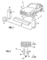
- FIG. 1 shows a schematic representation of a measuring system 2 according to the invention with a vehicle 4, the vibration damper to be checked according to the invention.
- the measuring system 2 comprises an elongated threshold with a defined height, the main extension direction of which is arranged substantially transversely or substantially at a right angle to the direction of movement 6 of the vehicle 4.
- the length of the threshold 8 corresponds at least to the width of the vehicle 4, so that when crossing the threshold 8 in each case two wheels 5 of the same axis of the Vehicle 4 through the threshold 8 experience a defined vertical excitation and are put into a vertical vibration.
- a left measuring head 10 and a right measuring head 12 are arranged in each case.
- Each of the measuring heads each has at least one measuring camera 11 directed inwards in the direction of the vehicle 4, which may be e.g. Includes CCD sensors.
- the measuring cameras 11 are mounted at a suitable height above the ground and capable of optically detecting the wheel 5 and the body 3 of the vehicle 4. In a method according to the invention, a number of images which form an image sequence are recorded with each of the measuring cameras 11 while the vehicle 4 travels over the threshold 8.
- the measuring system 2 furthermore has a data processing unit 9 which receives the image sequences recorded by the measuring cameras 11 of the measuring heads 10 and 12 and which is set up to carry out an evaluation method according to the invention.
- the measuring system 2 can additionally have a data input facility by means of which data for the vehicle 4 to be tested can be entered either manually via a connected keyboard or via a data link to another computer or by reading from a storage medium.
- FIG. 2 1 shows a schematic diagram of a vibration model 14.
- the vibration model 14 is a path-excited mass vibration system (EMS) with which the vibration between the body 3 and the motor vehicle wheel 5 can be described.
- EMS path-excited mass vibration system
- the vibration model 14 represents the observation of a quarter vehicle, ie, an axle with the proportional body mass mA.
- the vehicle mass or body mass mA is denoted by the reference numeral 20 and shown schematically as a rectangle.
- the wheel axle 22 or the wheel suspension is designated by the reference numeral 22.
- the vibration damper is formed by the spring 16 with the spring stiffness cA and the parallel attenuator 18 with the damping factor kA, and the body ground 20 is supported by this vibration damper on the wheel axle 22.
- the direction of movement of the vehicle wheel 5 or the wheel movement sR is shown with an upward arrow, and the direction of movement of the body mass 3 and the body movement sA is also shown with an upward arrow.
- the body ground 20 is caused to vibrate due to the movement of the vehicle wheel 5 and the transmission by the vibration damper.
- the optical flow is determined from the rectified image data.
- the basics for the calculation of the optical flow are eg by Berthold KP Horn and Brian G. Schunck in "Determining Optical Flow", Artificial Intelligence, vol. 17, no. 1-3, pp. 185-203, 1981 described.
- the real-time processing of the optical flow for example, based on an FPGA is eg by Zhaoyi Wei, Dah-Jye Lee, and Brent E. Nelson in "FPGA-based Real-time Optical Flow Algorithm Design and Implementation, Journal of Multimedia, Vol. 2, No. 5, September 2007, pages 38-44 From the mono video image data, a vector field is calculated between every two successive images, which corresponds to the determination of point correspondences and indicates the direction and speed of movement of these points.
- the flow field is segmented into flow vectors D1 on the vehicle body 3, flow vectors D2 on the wheel 5 and flow vectors D3 which are located neither on the vehicle body 3 nor on the wheel 5.
- the vectors of the two groups D1 and D2 differ in that the movement of the body 3 contains only translational components and the movement of the wheel 5 due to the rolling movement contains a mixture of a rotational movement and translational components.
- FIGS. 4a to 4c show, by way of example, a side view of the vehicle 4 with flow vectors D1, D2 and D3 determined from the recorded image sequence.
- the flow vectors D1, D2 and D3 are shown in the schematic, diagrammatic representation as crosses.
- all flow vectors D1, D2, D3 are shown.
- Only the flow vectors D1 are shown, which have been assigned in the segmentation of the body 3 and in the Figure 4c only the flow vectors D2, which have been assigned to the wheel 5 during the segmentation, are shown.
- the parameters H are determined in the evaluation model E.
- the segmented flow fields D1, D2, D3 serve as input data.
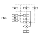
- FIG. 5 is an evaluation model for the simultaneous determination of the wheel centers and the body movements of all to be considered times of the video sequence and the attenuation, which is explained in more detail below, shown.
- step E1 a normal equation system is set up.
- the functional model F1 and for the flow vectors D2 of the wheel 5 the functional model F2 is applied.
- the oscillation equation F3 is introduced as a conditional equation between the unknown quantities of the functional models F1, F2. It has a regularizing effect and leads to the determination of the desired attenuation measure.
- step E2 the normal equation system is solved. With the parameters determined in step E2, the input segmentation is revised in E3. It is checked on the basis of the now improved certain parameters, whether from the flow vectors D3, which have been assigned neither the body nor the wheel, but vectors are in one of these areas. Conversely, it is also checked whether the vectors currently classified as D1 or D2 are correctly assigned. Iteratively, the revised segmentation results in E1 are used to construct the normal equation system. This process is repeated until G finds the convergence of the balancing process. The final determined parameters H are the sought result.
- u Axi u Ayi F 1 ⁇ P Ai - 1 T i T i - 1
- P ai-1 is a body point in image i-1, from which the flux u Axi , u Ayi results
- T i , T i-1 is the reference point on the body at time i and i-1, respectively.
- the body movement Z Ai and the wheel movement Z Ri can be simplified in a simplified manner as movement in the z direction of the reference point on the body T i and the center of rotation D i in image coordinates. This implies the assumption that the suspension is perpendicular to the direction of travel of the vehicle 4. Since the damping constant only describes a decay of the oscillation, no true-to-scale connection between the real world [mm] and the image coordinates [pixel] has to be established. The motion is calculated directly in pixel coordinates.
- the least squares sums of the deviations of the simultaneously considered functional models F1, F2 and F3 are minimized according to the method of least squares.
- the solution is done according to standard methods of the adjustment calculation, as for example by W. Niemeier in "Ausreteungsmarin, de Gruyter, Berlin - New York 2002, ISBN 3-11-014080-2 " to be discribed.
- multiple cameras 4 per vehicle side are used.
- a smaller distance between the opposing measuring heads 10, 12 can be realized.
- several cameras or measuring heads 10, 12 must be installed laterally along the direction of travel on each side of the vehicle 4. The advantage is that a very narrow system structure can be realized, which is only slightly wider than the vehicle width.
- an equalization is performed on a common reference plane. Subsequently, the optical flow is calculated and carried out the evaluation procedure already described.
- the method is performed without the image rectification step.
- the optical flow vectors become the distorted original video camera images calculated.
- the flux vectors are corrected for the geometric distortion or the distortion is taken into account in the functional model in the calculation of the attenuation measure ( ⁇ ).
- ⁇ the attenuation measure
Landscapes
- Engineering & Computer Science (AREA)
- Physics & Mathematics (AREA)
- General Physics & Mathematics (AREA)
- Theoretical Computer Science (AREA)
- Computer Vision & Pattern Recognition (AREA)
- Multimedia (AREA)
- Quality & Reliability (AREA)
- Image Analysis (AREA)
- Length Measuring Devices By Optical Means (AREA)
- Image Processing (AREA)
- Traffic Control Systems (AREA)
Description
- Die Erfindung betrifft ein Verfahren und eine Vorrichtung zum Bestimmen von Rad- und Karosseriebewegungen eines Fahrzeuges, insbesondere ein Verfahren und eine Vorrichtung zur Stoßdämpferprüfung mit Hilfe von Videobildsequenzen eines vorbeifahrenden Fahrzeugs.
-
EP 0 611 960 B1 undDE 43 05 048 A1 beschreiben Verfahren zum Prüfen eines Schwingungsdämpfers eines Kraftfahrzeugs. Bei den Verfahren wird ein auf einer Radaufstandsfläche aufstehendes Kraftfahrzeugrad durch Fußpunkterregungsschwingungen in Schwingungen versetzt. Das Dämpfungsverhalten des sich in der Radaufhängung des Kraftfahrzeugs befindlichen Schwingungsdämpfers kann bestimmt werden, indem die Differenzen aus den Bewegungsamplituden und den Bewegungsgeschwindigkeiten des Rads und denen des Fahrzeugaufbaus mit der Beschleunigung des Rads oder der dynamischen Aufstandskraft in Beziehung gesetzt werden und der Dämpfungskoeffizient aus dieser Beziehung geschätzt wird. Zur Qualitätsprüfung des Schwingungsdämpfers wird der geschätzte Dämpfungskoeffizient mit einem Referenzwert verglichen und festgestellt, ob eine Abweichung vom Referenzwert innerhalb des Toleranzbereichs liegt. -
EP 1 224 449 B1 undDE 10 2008 002 484 A1 beschreiben die optische Messung von Radzentren und Karosseriebewegungen sowie deren Auswertungen zur Bestimmung des Dämpfungsmaßes zur Charakterisierung des Stoßdämpfers mit Hilfe z.B. des Einmassen-Schwinger-Modells (EMS) aus den Daten eines vorbeifahrenden und in Schwingung versetzten Fahrzeugs. - Es ist eine Aufgabe der Erfindung, ein verbessertes Verfahren zur Messung von Rad- und Aufbaubewegungen eines Fahrzeugs und eine Vorrichtung zur Durchführung eines solchen Verfahrens bereit zu stellen.
- Die Aufgabe wird durch ein Verfahren nach dem unabhängigen Patentanspruch 1 und eine Messvorrichtung nach dem unabhängigen Patentanspruch 7 gelöst.
- Ein erfindungsgemäßes Verfahren zum Bestimmen von Rad- und Karosseriebewegungen eines Fahrzeuges umfasst die Schritte: Anregen einer Bewegung des Fahrzeugs; Aufnehmen einer mehrere Bilder umfassenden Bildsequenz des sich bewegenden Fahrzeugs; Bestimmen des optischen Flusses aus den Bildern der aufgenommenen Bildsequenz; und Bestimmen der Position wenigstens eines Radzentrums, der Bewegung der Karosserie und/oder eines Dämpfungsmaßes des Fahrzeugs aus dem optischen Fluss.
- Die Erfindung umfasst auch eine Messvorrichtung zum Bestimmen von Rad- und Karosseriebewegungen eines Fahrzeugs mit wenigstens einer Kamera, die zur Aufnahme einer Bildsequenz des Fahrzeugs ausgebildet ist; mit einer Berechnungsvorrichtung, die zur Berechnung des optischen Flusses aus der aufgenommenen Bildsequenz ausgebildet ist; und mit einer Auswertvorrichtung, die zur Bestimmung der Position wenigstens eines Radzentrums, der Bewegung der Karosserie und/oder des Dämpfungsmaßes aus dem optischen Fluss ausgebildet ist.
- Die erfindungsgemäße Auswertung des optischen Flusses ermöglicht eine Auswertung allein aus der Bewegung von Bildmerkmalen und erlaubt es, auf jegliche Modellierung des Bildinhalts, wie z.B. eines kreisförmigen Felgenrandes oder der rotationssymmetrischen Gestaltung des Rades zu verzichten. Sie ist robust und für eine Vielzahl unterschiedlicher Fahrzeugtypen einsetzbar. Sie ist damit besonders für den praktischen Einsatz in Werkstätten geeignet, wo eine große Variabilität der zu prüfenden Fahrzeuge zu erwarten ist.
- In einer Ausführungsform werden die Position wenigstens eines Radzentrums, die Bewegung der Karosserie und das Dämpfungsmaß simultan bestimmt. Durch die simultane Bestimmung der Rad- und Karosseriebewegung sowie des Dämpfungsmaßes ist das Verfahren eine aus Sicht der "Methode der kleinsten Quadrate" bestmögliche Dämpfungsbestimmung aus den Daten der Videokamera, da keine Zwischengrößen abgeleitet werden, sondern die Beobachtungen (hier: optischer Fluss) mit den Unbekannten (hier: Schwingungsmodell, z.B. Einmassenschwingsystem EMS) in funktionaler Beziehung stehen. Aufgrund der Regularisierung ist das Verfahren robust gegenüber Messfehlern in der Bildsequenz und systematische Fehler bei der Bestimmung des Dämpfungsmaßes im Verfahren werden weitgehend vermieden.
- In einer Ausführungsform umfasst das Verfahren den Schritt des Eliminierens geometrischer Verzerrungen in den aufgenommenen Bildern (geometrische Entzerrung). Vorteil der geometrischen Entzerrung ist eine starke Vereinfachung der mathematischen Modellierung für das Verfahren zur Auswertung des optischen Flusses. Die geometrische Entzerrung ist vergleichbar mit einer z.B. in der Photogrammetrie bekannten Fassadenentzerrung, siehe z.B. "Thomas Luhmann, Nahbereichsphotogrammetrie, Grundlagen - Methoden -Anwendungen, 2. Auflage, 586 Seiten, 2003".
- In einer Ausführungsform des Verfahrens wird das Flussfeld aus der Bestimmung des optischen Flusses segmentiert. Eine solche Segmentierung vereinfacht die folgende Auswertung des Flussfeldes.
- In einer Ausführungsform des Verfahrens umfasst das Segmentieren, das Flussfeld in Flussvektoren auf dem Rad, Flussvektoren auf der Karosserie und Flussvektoren, die weder auf dem Rad noch auf der Karosserie angeordnet sind, zu segmentieren. Eine derartige Segmentierung des Flussfeldes hat sich als besonders vorteilhaft für die folgende Auswertung erwiesen.
- In einer Ausführungsform des Verfahrens umfasst das Auswerten des Flussfeldes die Verwendung eines Gauß-Markoff-Modells nach der Methode der kleinsten Quadrate (siehe z.B. "W. Niemeier: Ausgleichungsrechnung, de Gruyter, Berlin - New York 2002, ISBN 3-11-014080-2"). Das Gauß-Markoff-Modell ermöglicht eine effektive und genaue Auswertung des Flussfeldes.
- In einer Ausführungsform weist die Vorrichtung wenigstens eine Mono-Kamera, eine Stereo-Kamera oder ein Mehrkamerasystem auf. Eine Vorrichtung mit einer Mono-Kamera ist besonders kostengünstig; eine Vorrichtung mit einer Stereo-Kamera oder Mehrkamerasystemen ermöglicht eine besonders genaue Bestimmung der Parameter.
- In einer Ausführungsform weist die Messvorrichtung wenigstens ein Mittel auf, das geeignet ist, eine Bewegung des Fahrzeugs anzuregen. Durch ein solches Anregungsmittel kann die zur Durchführung des erfindungsgemäßen Verfahrens notwendige Bewegung des Fahrzeugs besonders einfach und reproduzierbar angeregt werden.
- In einer Ausführungsform ist die Messvorrichtung derart ausgebildet, dass die Bildaufnahme durch mehrere Kameras synchron erfolgt und ein erweitertes Fahrzeugmodell für die Auswertung der aufgenommenen Bildsequenzen verwendet wird. Dadurch kann die Genauigkeit der Parameterbestimmung noch weiter erhöht werden.
- Die Erfindung wird im Folgenden anhand der Figuren näher erläutert:
-
Figur 1 zeigt eine schematische Darstellung eines erfindungsgemäßen Messsystems mit einem Fahrzeug; -
Figur 2 zeigt eine Prinzipskizze eines Schwingungsmodells; -
Figur 3 zeigt schematisch die Verarbeitung der von einer der Messkameras aufgenommenen Videobilddaten in einem erfindungsgemäßen Verfahren; -
Figuren 4a, 4b, 4c zeigen die Segmentierung der Flussvektoren; und -
Figur 5 zeigt ein Auswertemodell zur simultanen Bestimmung der Radzentren und der Karosseriebewegungen. -
Figur 1 zeigt eine schematische Darstellung eines erfindungsgemäßen Messsystems 2 mit einem Fahrzeug 4, dessen Schwingungsdämpfer erfindungsgemäß überprüft werden sollen. - Das Messsystem 2 umfasst eine längliche Schwelle mit definierter Höhe, deren Haupterstreckungsrichtung im Wesentlichen quer bzw. im Wesentlichen in einem rechten Winkel zu der Bewegungsrichtung 6 des Fahrzeugs 4 angeordnet ist. Die Länge der Schwelle 8 entspricht wenigstens der Breite des Fahrzeugs 4, so dass beim Überfahren der Schwelle 8 jeweils zwei Räder 5 der gleichen Achse des Fahrzeugs 4 durch die Schwelle 8 eine definierte vertikale Anregung erfahren und in eine vertikale Schwingung versetzt werden.
- Auf beiden Seiten der Schwelle 8, entweder auf Höhe der Schwelle 8 oder in Fahrtrichtung des Fahrzeugs 4 kurz hinter der Schwelle 8, ist jeweils ein linker Messkopf 10 und ein rechter Messkopf 12 angeordnet. Jeder der Messköpfe weist jeweils wenigstens eine nach innen in Richtung auf das Fahrzeug 4 gerichtete Messkamera 11, die z.B. CCD-Sensoren umfasst, auf. Die Messkameras 11 sind in geeigneter Höhe über dem Boden angebracht und in der Lage, das Rad 5 und die Karosserie 3 des Fahrzeugs 4 optisch zu erfassen. In einem erfindungsgemäßen Verfahren wird mit jeder der Messkameras 11 eine Anzahl von Bildern, die eine Bildsequenz bilden, aufgenommen, während das Fahrzeug 4 über die Schwelle 8 fährt.
- Das Messsystem 2 verfügt des Weiteren über eine Datenverarbeitungseinheit 9, welche die von den Messkameras 11 der Messköpfe 10 und 12 aufgenommenen Bildsequenzen erhält und die eingerichtet ist, um ein erfindungsgemäßes Auswertverfahren durchzuführen.
- Das Messsystem 2 kann zusätzlich über eine Möglichkeit zur Dateneingabe verfügen, mittels derer Daten für das zu prüfende Fahrzeug 4 entweder manuell über eine angeschlossene Tastatur oder über eine Datenkopplung zu einem anderen Computer oder durch Einlesen von einem Speichermedium eingegeben werden können.
-
Figur 2 zeigt eine Prinzipskizze eines Schwingungsmodells 14. Das Schwingungsmodell 14 ist ein weg-angeregtes Einmassenschwingsystem (EMS), mit dem sich die Schwingung zwischen der Karosserie 3 und dem Kraftfahrzeugrad 5 beschreiben lässt. Das Schwingungsmodell 14 stellt die Betrachtung eines Viertelfahrzeugs dar, d. h., eine Achsseite mit der anteiligen Karosseriemasse mA. - Die Fahrzeugmasse bzw. Karosseriemasse mA ist mit dem Bezugszeichen 20 gekennzeichnet und schematisch als Rechteck dargestellt. Die Radachse 22 bzw. die Radaufhängung ist mit dem Bezugszeichen 22 gekennzeichnet. Der Schwingungsdämpfer wird von der Feder 16 mit der Federsteifigkeit cA und dem parallelen Dämpfungsglied 18 mit dem Dämpfungsfaktor kA gebildet, und die Karosseriemasse 20 ist durch diesen Schwingungsdämpfer auf der Radachse 22 gelagert.
- Die Richtung der Bewegung des Fahrzeugrads 5 bzw. der Radbewegung sR ist mit einem nach oben gerichteten Pfeil dargestellt, und die Richtung der Bewegung der Karosseriemasse 3 bzw. der Aufbaubewegung sA ist ebenfalls mit einem nach oben gerichteten Pfeil dargestellt.
- Die Karosseriemasse 20 wird aufgrund der Bewegung des Fahrzeugrads 5 und die Übertragung durch den Schwingungsdämpfer zum Schwingen angeregt.
-
Figur 3 beschreibt schematisch die Verarbeitung der von einer der Messkameras 11 aufgenommenen Videobilddaten in einem erfindungsgemäßen Verfahren: - Ausgehend von einer Mono-Videokamera 11 wird die aufgezeichnete Bildsequenz A einer dedizierten Rechenhardware zur Bildrektifizierung B1 übergeben. Die Bildrektifizierung ist zur vereinfachten Modellierung der funktionalen Modelle notwendig. Werden die Eingangsbilddaten nicht rektifiziert, kann die optische Verzerrung, die von der Aufnahmeoptik usw. verursacht wird, auch rechnerisch an das ermittelte Flussfeld angebracht werden. Die Bildrektifizierung ist ein Standardverfahren, welches z.B. auch bei der Berechnung von Stereo-Videobildern zum Einsatz kommt.
- Anschließend wird, ebenfalls auf einer dedizierten Rechenhardware B2, aus den rektifizierten Bilddaten der optische Fluss bestimmt. Die Grundlagen zur Berechnung des optischen Flusses werden z.B. von Berthold K. P. Horn und Brian G. Schunck in "Determining Optical Flow", Artificial Intelligence, vol. 17, no. 1-3, pp. 185-203, 1981 beschrieben. Die Echtzeitprozessierung des optischen Flusses z.B. basierend auf einem FPGA wird z.B. von Zhaoyi Wei, Dah-Jye Lee und Brent E. Nelson in "FPGA-based Real-time Optical Flow Algorithm Design and Implementation, Journal of Multimedia, Vol. 2, No. 5, September 2007, Seiten 38-44" beschrieben. Aus den Mono-Videobilddaten wird ein Vektorfeld zwischen jeweils zwei aufeinanderfolgenden Bildern berechnet. Dies entspricht der Bestimmung von Punktkorrespondenzen und gibt die Bewegungsrichtung und - geschwindigkeit dieser Punkte an.
- Im nächsten Schritt C wird das Flussfeld in Flussvektoren D1 auf der Fahrzeugkarosserie 3, Flussvektoren D2 auf dem Rad 5 und Flussvektoren D3, die weder auf der Fahrzeugkarosserie 3 noch auf dem Rad 5 liegen, segmentiert. Die Vektoren der beiden Gruppen D1 und D2 unterscheiden sich dadurch, dass die Bewegung der Karosserie 3 nur translatorische Anteile enthält und die Bewegung des Rades 5 aufgrund der Rollbewegung eine Mischung aus einer Drehbewegung und translatorischen Anteilen enthält.
- Die Segmentierung gehorcht dabei folgenden Regeln:
- Alle Vektoren, die eine Dreh- und Translationsbewegung enthalten, welche mit der höchsten Häufigkeit in dem Vektorfeld auftritt, werden als Radvektoren D2 klassifiziert. Alle Vektoren, die nur eine Translationsbewegung enthalten, welche mit der höchsten Häufigkeit in dem Vektorfeld auftritt, werden als Karosserievektoren klassifiziert D1.
- Die
Figuren 4a bis 4c zeigen beispielhaft eine Seitenansicht des Fahrzeugs 4 mit aus der aufgenommenen Bildsequenz bestimmten Flussvektoren D1, D2 und D3. Die Flussvektoren D1, D2 und D3 sind dabei in der schematischen, zeichnerischen Darstellung als Kreuze dargestellt. In derFigur 4a sind alle Flussvektoren D1, D2, D3 gezeigt. In derFigur 4b sind nur die Flussvektoren D1 gezeigt, die bei der Segmentierung der Karosserie 3 zugeordnet worden sind und in derFigur 4c sind nur die Flussvektoren D2 gezeigt, die bei der Segmentierung dem Rad 5 zugeordnet worden sind. - Sind alle Bilder der aufgenommenen Sequenz von dem in Schwingung versetzten Fahrzeug 4 verarbeitet worden, werden die Parameter H, unter anderem der gesuchte Dampfungsparameter, im Auswertemodell E bestimmt. Als Eingangsdaten dienen dabei die segmentierten Flussfelder D1, D2, D3.
- In
Figur 5 ist ein Auswertemodell zur simultanen Bestimmung der Radzentren und der Karosseriebewegungen aller zu berücksichtigenden Zeitpunkte der Videosequenz sowie des Dämpfungsmaßes, welches im Folgenden näher erläutert wird, dargestellt. - Die Lösung erfolgt in einem Gauß-Markoff-Modell nach der Methode der kleinsten Quadrate. Im Schritt E1 wird ein Normalgleichungssystem aufgebaut. Für Flussvektoren D1 der Fahrzeugkarosserie 3 wird das funktionale Modell F1 und für die Flussvektoren D2 des Rades 5 das funktionale Modell F2 angewendet. Die Schwingungsgleichung F3 wird als Bedingungsgleichung zwischen den unbekannten Größen der funktionalen Modelle F1, F2 eingeführt. Sie wirkt regularisierend und führt zur Bestimmung des gesuchten Dämpfungsmaßes.
- Im Schritt E2 wird das Normalgleichungssystem gelöst. Mit den im Schritt E2 bestimmten Parameter wird in E3 die Eingangssegmentierung überarbeitet: Es wird anhand der nun verbessert bestimmten Parametern geprüft, ob aus den Flussvektoren D3, die bislang weder der Karosserie noch dem Rad zugeordnet worden sind, doch Vektoren in einem dieser Bereiche liegen. Im Umkehrschluss wird auch geprüft, ob die derzeit als D1 bzw. D2 klassifizierte Vektoren richtig zugeordnet sind. Iterativ werden die überarbeiteten Segmentierungsergebnisse in E1 zur Aufstellung des Normalgleichungssystems verwendet. Dieser Prozess wird solange wiederholt, bis in G die Konvergenz des Ausgleichsprozesses festgestellt wird. Die final bestimmten Parameter H sind das gesuchte Ergebnis.
- Für die Auswertung stehen die zuvor bestimmten Flussvektoren
- D1: u Ai = [uAxi uAyi] von Karosseriepunkten (PAi) und
- D2: u Ri = [uRxi uRyi] von Radpunkten (Pri)
- Zu bestimmen sind die Parameter:
- Dämpfungsmaß Θ,
- das Drehzentrum Zi zu jedem Zeitpunkt i der Bildsequenz, und
- ein fester Bezugspunkt auf der Karosse TAi, dessen Bewegung über die Bildsequenz bestimmt wird. Er dient zur Bestimmung der Federbewegung des Rades.
-

wobei Pai-1 ein Karosseriepunkt im Bild i-1 ist, woraus sich der Fluss uAxi, uAyi ergibt, und Ti, Ti-1 der Bezugspunkt auf der Karosserie zum Zeitpunkt i bzw. i-1 ist. -

wobei - PRi-1
- ein Radpunkt im Bilde i-1,
- Di, Di-1
- Drehzentren des Rades zum Zeitpunkt i bzw. i-1, und
- Δαi,
- der differenzielle Rollwinkel des Rades sind.
- Bewegt sich das Fahrzeug 4 parallel zur Bildebene, so können die Aufbaubewegung ZAi und die Radbewegung ZRi vereinfacht als Bewegung in z-Richtung des Bezugspunkt auf der Karosserie Ti und des Drehzentrums Di in Bildkoordinaten approximiert werden. Dies impliziert die Annahme, dass sich die Federung senkrecht zur Fahrtrichtung des Fahrzeuges 4 auswirkt. Da die Dämpfungskonstante nur ein Abklingen der Schwingung beschreibt, muss keine maßstäbliche Verbindung zwischen der realen Welt [mm] und den Bildkoordinaten [Pixel] hergestellt werden. Die Bewegung wird vielmehr direkt in Pixelkoordinaten berechnet.
- Die Differentialgleichung des Einmassenschwingers lautet:

- Für die Funktion F3 gilt damit:

wobei: - ω0 die Eigenfrequenz des Aufbaus,
- δ eine Abklingkonstante,
- Z"Ai die Beschleunigung des Aufbaus in Pixel/s2,
- Z'Ai die Geschwindigkeit des Aufbaus in Pixel/s,
- Z'Ri die Geschwindigkeit des Rades in Pixel/s,
- ZAi die Position des Aufbaus in Pixel, und
- ZRi die Position des Rades in Pixel ist.
- Das zur Beurteilung des Schwingungsdämpfers verwendete Lehr'sche Dämpfungsmaß ist definiert als Quotient aus Abklingkonstante und Aufbaueigenfrequenz:

- Mit den funktionalen Modellen in den Gleichung (1), (2) und (4) ist gezeigt, wie die Flussvektoren mit den gesuchten Unbekannten zur Bestimmung des Dämpfungsmaßes (Θ) in direkter Beziehung stehen. Weiter wird deutlich, dass als Eingangsdaten Flussvektoren ausreichen, welche ausschließlich die Beziehung zwischen zwei Bildern beschreiben. Es sind also keine Trajektorien von Merkmalspunkten über die gesamte Videosequenz erforderlich, wodurch das Verfahren einfach realisierbar ist.
- Zur Bestimmung der genannten Parameter werden gemäß der Methode der kleinsten Quadrate die Quadratsummen der Abweichungen der gleichzeitig betrachteten funktionalen Modelle F1, F2 und F3 minimiert. Die Lösung erfolgt nach Standardverfahren der Ausgleichungsrechnung, wie sie beispielsweise von W. Niemeier in "Ausgleichungsrechnung, de Gruyter, Berlin - New York 2002, ISBN 3-11-014080-2" beschrieben werden.
- In einer möglichen Variante werden mehrerer Kameras 4 je Fahrzeugseite verwendet. Dadurch ist geringerer Abstand zwischen den einander gegenüberliegenden Messköpfen 10, 12 realisierbar. Um das gleiche Sichtfeld zu erreichen, müssen dann auf jeder Seite des Fahrzeugs 4 mehrere Kameras bzw. Messköpfe 10, 12 seitlich entlang der Fahrtrichtung installiert werden. Der Vorteil ist, dass ein sehr schmaler Systemaufbau realisierbar ist, der nur geringfügig breiter als die Fahrzeugbreite ist. Für die Auswertung mehrere Kamerabilder pro Seite erfolgt jeweils eine Entzerrung auf eine gemeinsame Bezugsebene. Anschließend wird der optische Fluss berechnet und die bereits beschriebene Auswerteprozedur durchgeführt.
- In einer Variante wird das Verfahren ohne den Schritt der Bildrektifizierung durchgeführt. Die optischen Flussvektoren werden aus den verzerrten Original-Videokamerabildern berechnet. Anschließend werden die Flussvektoren um die geometrische Verzerrung korrigiert oder die Verzerrung wird in dem funktionalen Modell bei der Berechnung des Dämpfungsmaßes (Θ) berücksichtigt. Abhängig von der Dichte des Flussfeldes bzw. der Anzahl der Flussvektoren kann des zu einer Optimierung der für die Durchführung des Verfahrens notwendigen Rechenzeit führen.
- Optional kann die funktionale Modellierung, um Parameter, die
- a) eine Verkippung der Bildebene und der Fahrzeugbewegungsebene,
- b) Tiefenänderungen zwischen einzelnen Rad- und Karosseriepunkten, und /oder
- c) Abweichungen von der senkrechten Bewegung der Radfederung (Schrägfederwinkel) beschreiben, erweitert werden, um die Genauigkeit des Verfahrens zu verbessern.
Claims (10)
- Verfahren zum Bestimmen von Rad- und Karosseriebewegungen eines Fahrzeugs (4) mit einer Karosserie (3) und wenigstens einem Rad (5), wobei das Verfahren die Schritte umfasst:- Anregen einer Bewegung des Fahrzeugs (4);- Aufnehmen einer Bildsequenz (A) von Bildern des sich bewegenden Fahrzeugs (4);
gekennzeichnet durch die Schritte- Bestimmen des optischen Flusses aus den aufgenommenen Bildern der Bildsequenz (A); und- Bestimmen der Position wenigstens eines Radzentrums (22), der Bewegung der Karosserie (3) und/oder eines Dämpfungsmaßes (Θ) des Fahrzeugs (4) aus dem optischen Fluss. - Verfahren nach Anspruch 1, wobei die Position wenigstens eines Radzentrums (22), die Bewegung der Karosserie (3) und das Dämpfungsmaß (Θ) simultan bestimmt werden.
- Verfahren nach Anspruch 1 oder 2, welches zusätzlich den Schritt des Eliminierens geometrischer Verzerrungen in den aufgenommenen Bildern umfasst.
- Verfahren nach einem der vorangehenden Ansprüche, wobei das Bestimmen des optischen Flusses umfasst, das Flussfeld zu segmentieren.
- Verfahren nach Anspruch 4, wobei das Segmentieren umfasst, das Flussfeld in Flussvektoren (D2) auf dem Rad (5), Flussvektoren (D1) auf der Karosserie (3) und Flussvektoren (D3), die weder auf dem Rad (5) noch auf der Karosserie (3) angeordnet sind, zu segmentieren.
- Verfahren nach Anspruch 2, wobei das Bestimmen eines Dämpfungsmaßes die Verwendung eines Gauß-Markoff-Modell nach der Methode der kleinsten Quadrate umfasst.
- Messvorrichtung zum Bestimmen von Rad- und Karosseriebewegungen eines Fahrzeugs (4), das eine Karosserie (3) und wenigstens ein Rad (5) hat, mit:wenigstens einer Kamera (11), die zur Aufnahme einer Bildsequenz (A) von Bildern des Fahrzeugs (4) ausgebildet ist;
gekennzeichnet durcheine Berechnungsvorrichtung (9), die zur Berechnung des optischen Flusses aus der aufgenommenen Bildsequenz (A) ausgebildet ist; undeine Auswertvorrichtung (9), die zur Bestimmung der Position wenigstens eines Radzentrums (22), der Bewegung der Karosserie (3) und/oder des Dämpfungsmaßes (Θ) aus dem optischen Fluss ausgebildet ist. - Vorrichtung nach Anspruch 7, wobei die Kamera (11) eine Mono-Kamera, eine Stereo-Kamera oder ein Mehrkamerasystem ist.
- Vorrichtung nach Anspruch 7 oder 8, wobei die Messvorrichtung wenigstens ein Mittel (8) umfasst, das geeignet ist, eine Bewegung des Fahrzeugs (4) anzuregen.
- Vorrichtung nach einer der Ansprüche 7 bis 9, die derart ausgebildet ist, dass die Bildaufnahme durch die mehreren Kameras (11) synchron erfolgt und ein erweitertes Fahrzeugmodell für die Auswertung der aufgenommenen Bildsequenzen (A) verwendet wird.
Applications Claiming Priority (2)
| Application Number | Priority Date | Filing Date | Title |
|---|---|---|---|
| DE102010038905A DE102010038905A1 (de) | 2010-08-04 | 2010-08-04 | Verfahren und Vorrichtung zum Bestimmen von Rad- und Karosseriebewegungen eines Fahrzeuges |
| PCT/EP2011/062247 WO2012016813A1 (de) | 2010-08-04 | 2011-07-18 | Verfahren und vorrichtung zum bestimmen von rad- und karosseriebewegungen eines fahrzeuges |
Publications (2)
| Publication Number | Publication Date |
|---|---|
| EP2601503A1 EP2601503A1 (de) | 2013-06-12 |
| EP2601503B1 true EP2601503B1 (de) | 2014-09-10 |
Family
ID=44543192
Family Applications (1)
| Application Number | Title | Priority Date | Filing Date |
|---|---|---|---|
| EP11739029.4A Not-in-force EP2601503B1 (de) | 2010-08-04 | 2011-07-18 | Verfahren und vorrichtung zum bestimmen von rad- und karosseriebewegungen eines fahrzeuges |
Country Status (6)
| Country | Link |
|---|---|
| US (1) | US20130188839A1 (de) |
| EP (1) | EP2601503B1 (de) |
| JP (1) | JP5665985B2 (de) |
| CN (1) | CN103026198B (de) |
| DE (1) | DE102010038905A1 (de) |
| WO (1) | WO2012016813A1 (de) |
Families Citing this family (14)
| Publication number | Priority date | Publication date | Assignee | Title |
|---|---|---|---|---|
| WO2014151666A1 (en) | 2013-03-15 | 2014-09-25 | Hunter Engineering Company | Method for determining parameters of a rotating object within a projected pattern |
| DE102013112976A1 (de) * | 2013-09-30 | 2015-04-02 | Hochschule für Technik und Wirtschaft Dresden | Anordnung und Verfahren zur Ermittlung von Fahrwerks- und anderen Eigenschaften eines Fahrzeugs |
| ITBO20130697A1 (it) | 2013-12-19 | 2015-06-20 | Corghi Spa | Apparato e metodo di valutazione diagnostica dell'assetto di un veicolo |
| US9616350B2 (en) | 2014-05-21 | 2017-04-11 | Universal City Studios Llc | Enhanced interactivity in an amusement park environment using passive tracking elements |
| US10061058B2 (en) | 2014-05-21 | 2018-08-28 | Universal City Studios Llc | Tracking system and method for use in surveying amusement park equipment |
| US9600999B2 (en) | 2014-05-21 | 2017-03-21 | Universal City Studios Llc | Amusement park element tracking system |
| US10025990B2 (en) | 2014-05-21 | 2018-07-17 | Universal City Studios Llc | System and method for tracking vehicles in parking structures and intersections |
| US10207193B2 (en) | 2014-05-21 | 2019-02-19 | Universal City Studios Llc | Optical tracking system for automation of amusement park elements |
| US9433870B2 (en) | 2014-05-21 | 2016-09-06 | Universal City Studios Llc | Ride vehicle tracking and control system using passive tracking elements |
| US9429398B2 (en) | 2014-05-21 | 2016-08-30 | Universal City Studios Llc | Optical tracking for controlling pyrotechnic show elements |
| JP2016192177A (ja) * | 2015-03-31 | 2016-11-10 | 株式会社デンソーアイティーラボラトリ | 車両検出システム、車両検出装置、車両検出方法、及び車両検出プログラム |
| US9952304B2 (en) * | 2015-09-10 | 2018-04-24 | Ford Global Technologies, Llc | Vehicle positioning system |
| CN106651881B (zh) * | 2016-12-28 | 2023-04-28 | 同方威视技术股份有限公司 | 车辆检查系统、车辆部位识别方法及系统 |
| DE102018113138A1 (de) * | 2018-06-01 | 2019-12-05 | Neimcke GmbH & Co. KG | Anordnung sowie Verfahren zum Erfassen und/oder Auswerten von Schwingungen |
Family Cites Families (31)
| Publication number | Priority date | Publication date | Assignee | Title |
|---|---|---|---|---|
| US9031A (en) * | 1852-06-15 | Improvement in harvesters | ||
| US2004A (en) * | 1841-03-12 | Improvement in the manner of constructing and propelling steam-vessels | ||
| JPS5431601U (de) * | 1977-08-05 | 1979-03-01 | ||
| JPS566135A (en) * | 1979-06-28 | 1981-01-22 | Tokico Ltd | Shock absorber testing device of vehicle |
| JPS57118124A (en) * | 1981-01-14 | 1982-07-22 | Yasaka Seiki Kk | Method and device for automatic displacement detection |
| JPS6382901U (de) * | 1986-11-19 | 1988-05-31 | ||
| US5767382A (en) * | 1988-06-25 | 1998-06-16 | Liquid Levers Limited | Method and apparatus for testing shock absorbers and/or suspension system in motor vehicles |
| US5034986A (en) * | 1989-03-01 | 1991-07-23 | Siemens Aktiengesellschaft | Method for detecting and tracking moving objects in a digital image sequence having a stationary background |
| FR2644886B1 (fr) * | 1989-03-24 | 1993-12-10 | Celette Sa | Dispositif de controle de la position de differents points d'un vehicule |
| DE4305048C2 (de) | 1993-02-18 | 2002-09-26 | Snap On Deutschland Holding | Verfahren zum Prüfen eines Schwingungsdämpfers eines Kraftfahrzeugs |
| DE4431794A1 (de) * | 1994-09-06 | 1996-03-07 | Langlechner Richard Gmbh | Verfahren und Vorrichtung zur Bestimmung der Eigenschaften der in einem Kraftfahrzeug eingebauten Stoßdämpfer |
| JP3055868B2 (ja) * | 1995-11-30 | 2000-06-26 | 日産自動車株式会社 | ショックアブソーバの減衰力測定装置 |
| IT1294940B1 (it) * | 1997-08-01 | 1999-04-23 | Corghi Spa | Metodo e dispositivo per regolare l'assetto di un autoveicolo |
| DE19757763A1 (de) * | 1997-12-23 | 1999-07-01 | Bosch Gmbh Robert | Vorrichtung zum Bestimmen der Rad- und/oder Achsgeometrie von Kraftfahrzeugen |
| JPH11211625A (ja) * | 1998-01-22 | 1999-08-06 | Saginomiya Seisakusho Inc | 車両基本特性測定装置及びその制御方法 |
| JP3452188B2 (ja) * | 1999-05-27 | 2003-09-29 | 理化学研究所 | 2次元動画像中の特徴点の追跡方法 |
| DE19934864A1 (de) * | 1999-07-24 | 2001-02-08 | Bosch Gmbh Robert | Vorrichtung zum Bestimmen der Rad- und/oder Achsgeometrie von Kraftfahrzeugen |
| DE19949704A1 (de) * | 1999-10-15 | 2001-05-10 | Bosch Gmbh Robert | Verfahren und Einrichtung zum Bewerten des Spieles in Lagern oder Gelenken miteinander gekoppelter Bauteile |
| DE19949982C2 (de) * | 1999-10-16 | 2002-11-14 | Bosch Gmbh Robert | Verfahren und Einrichtung zum Überprüfen von Radaufhängungskomponenten |
| BE1013152A3 (nl) * | 1999-11-24 | 2001-10-02 | Krypton Electronic Eng Nv | Werkwijze voor het bepalen van het dynamisch gedrag van een voertuig op een testbank. |
| JP3725442B2 (ja) * | 2001-04-18 | 2005-12-14 | 株式会社東芝 | 医用画像診断装置及びその方法 |
| JP2003097915A (ja) * | 2001-09-27 | 2003-04-03 | Mazda Motor Corp | 車輪挙動計測装置及び当該システム、並びに車輪状態解析装置 |
| US7697698B2 (en) * | 2003-08-22 | 2010-04-13 | William Sumner Brown | Sound-based vehicle safety system |
| DE102004013441A1 (de) * | 2004-03-18 | 2005-10-13 | Beissbarth Gmbh | Meßverfahren und Meßgerät zur Bestimmung der räumlichen Lage einer Radfelge sowie Fahrwerkvermessungseinrichtung |
| US7298319B2 (en) * | 2004-04-19 | 2007-11-20 | Magellan Navigation, Inc. | Automatic decorrelation and parameter tuning real-time kinematic method and apparatus |
| DE102005000651A1 (de) * | 2005-01-04 | 2006-07-13 | Robert Bosch Gmbh | Verfahren zur Bestimmung der Eigenbewegung eines Fahrzeugs |
| DE102008002484A1 (de) | 2008-06-17 | 2009-12-24 | Robert Bosch Gmbh | Verfahren zum Prüfen eines Schwingungsdämpfers eines Kraftfahrzeugs im eingebauten Zustand sowie Schwingungsdämpfer-Prüfsystem für ein Kraftfahrzeug |
| DE102008041732A1 (de) * | 2008-09-01 | 2010-03-04 | Robert Bosch Gmbh | Fahrwerksprüfungseinrichtung sowie Verfahren zum Prüfen eines Fahrwerks |
| DE102008042223A1 (de) * | 2008-09-19 | 2010-04-01 | Robert Bosch Gmbh | Anordnung zum Erfassen und Auswerten einer Fahrzeugbewegung in einem vorgegebenen Überwachungsbereich |
| JP4530088B2 (ja) * | 2008-10-30 | 2010-08-25 | トヨタ自動車株式会社 | 車両停止状態の検出装置、検出方法およびアライメント調整装置 |
| DE102008054975A1 (de) * | 2008-12-19 | 2010-07-01 | Robert Bosch Gmbh | Verfahren zur Fahrwerksvermessung sowie Vorrichtung zum Vermessen der Fahrwerksgeometrie eines Fahrzeugs |
-
2010
- 2010-08-04 DE DE102010038905A patent/DE102010038905A1/de not_active Withdrawn
-
2011
- 2011-07-18 CN CN201180037980.7A patent/CN103026198B/zh not_active Expired - Fee Related
- 2011-07-18 WO PCT/EP2011/062247 patent/WO2012016813A1/de not_active Ceased
- 2011-07-18 US US13/814,199 patent/US20130188839A1/en not_active Abandoned
- 2011-07-18 JP JP2013522180A patent/JP5665985B2/ja not_active Expired - Fee Related
- 2011-07-18 EP EP11739029.4A patent/EP2601503B1/de not_active Not-in-force
Also Published As
| Publication number | Publication date |
|---|---|
| JP2013537630A (ja) | 2013-10-03 |
| DE102010038905A1 (de) | 2012-02-09 |
| US20130188839A1 (en) | 2013-07-25 |
| EP2601503A1 (de) | 2013-06-12 |
| WO2012016813A1 (de) | 2012-02-09 |
| CN103026198B (zh) | 2016-05-18 |
| CN103026198A (zh) | 2013-04-03 |
| JP5665985B2 (ja) | 2015-02-04 |
Similar Documents
| Publication | Publication Date | Title |
|---|---|---|
| EP2601503A1 (de) | Verfahren und vorrichtung zum bestimmen von rad- und karosseriebewegungen eines fahrzeuges | |
| EP2166510B1 (de) | Verfahren zum Ermitteln der Position und der Orientierung einer in einem Fahrzeug angeordneten Kamera | |
| DE112009001197B4 (de) | Selbstkalibrierung von extrinsischen Kameraparametern für eine Fahrzeugkamera | |
| EP2079982B1 (de) | Verfahren zum ermitteln der drehachse eines fahrzeugrades | |
| EP2049870B1 (de) | Verfahren zum bestimmen der drehachse und des drehzentrums eines fahrzeugrads | |
| EP2539117B1 (de) | Verfahren und vorrichtung zum bestimmen von abständen an einem fahrzeug | |
| WO2015173092A1 (de) | Verfahren und vorrichtung zur kalibrierung eines kamerasystems eines kraftfahrzeugs | |
| DE102016225595A1 (de) | Verfahren und Anordnung zur Kalibrierung mindestens eines Sensors eines Schienenfahrzeugs | |
| DE102008042145A1 (de) | Verfahren und Messanordnung zum Bestimmen der Rad-oder Achsgeometrie eines Fahrzeugs | |
| EP3612794B1 (de) | Verfahren und vorrichtung zur fahrwerksvermessung | |
| DE102017011177A1 (de) | Verfahren zum Ermitteln eines Knickwinkels eines Fahrzeug-Gespanns, Ermittlungseinrichtung sowie Fahrzeug-Gespann | |
| DE102017109445A1 (de) | Kalibration einer Fahrzeug-Kameraeinrichtung in Fahrzeuglängsrichtung oder Fahrzeugquerrichtung | |
| DE102015003666A1 (de) | Verfahren zur Verarbeitung von erfassten Messdaten eines Sensors | |
| DE102019003238B4 (de) | Fahrzeugortung durch Kartenabgleich unter Berücksichtigung eines Straßenprofils | |
| DE102014219423B4 (de) | Dynamisches Modell zur Kompensation von Verzeichnungen einer Windschutzscheibe | |
| DE102019114404A1 (de) | Bilderfassungssystem | |
| WO2018189249A1 (de) | Verfahren und eine vorrichtung zur messung von rotorblattbewegungen eines fluggerätes | |
| DE102017003629A1 (de) | Vorrichtung und Verfahren zur Kalibrierung optischer Sensoren eines Fahrzeugs | |
| EP3904827B1 (de) | Dynamische routenplanung einer drohnenbasierten überprüfung von streckeneinrichtungen einer strecke | |
| DE102011056948A1 (de) | Verfahren zur Kalibrierung einer Kamera zu einem Lagesensor | |
| WO2025113959A1 (de) | Verfahren zum erfassen einer ein phasenobjekt umfassenden szenerie | |
| EP4308971B1 (de) | Verfahren zur bestimmung eines bewegungszustands eines starren körpers | |
| DE102021133091B4 (de) | Verfahren zur Ermittlung einer Ausrichtung einer Kameraeinheit einer Erfassungseinrichtung, Erfassungseinrichtung und Fahrzeug | |
| DE102014219418B4 (de) | Verfahren zur Stereorektifizierung von Stereokamerabildern und Fahrerassistenzsystem | |
| WO2023186428A1 (de) | Kalibrierung und justierung einer kamera eines fahrzeugs |
Legal Events
| Date | Code | Title | Description |
|---|---|---|---|
| PUAI | Public reference made under article 153(3) epc to a published international application that has entered the european phase |
Free format text: ORIGINAL CODE: 0009012 |
|
| 17P | Request for examination filed |
Effective date: 20130304 |
|
| AK | Designated contracting states |
Kind code of ref document: A1 Designated state(s): AL AT BE BG CH CY CZ DE DK EE ES FI FR GB GR HR HU IE IS IT LI LT LU LV MC MK MT NL NO PL PT RO RS SE SI SK SM TR |
|
| DAX | Request for extension of the european patent (deleted) | ||
| REG | Reference to a national code |
Ref country code: DE Ref legal event code: R079 Ref document number: 502011004348 Country of ref document: DE Free format text: PREVIOUS MAIN CLASS: G01M0017040000 Ipc: G06K0009000000 |
|
| RIC1 | Information provided on ipc code assigned before grant |
Ipc: G01M 17/04 20060101ALI20131203BHEP Ipc: G06K 9/00 20060101AFI20131203BHEP Ipc: G06T 7/00 20060101ALI20131203BHEP Ipc: G06T 7/20 20060101ALI20131203BHEP |
|
| GRAP | Despatch of communication of intention to grant a patent |
Free format text: ORIGINAL CODE: EPIDOSNIGR1 |
|
| INTG | Intention to grant announced |
Effective date: 20140415 |
|
| GRAS | Grant fee paid |
Free format text: ORIGINAL CODE: EPIDOSNIGR3 |
|
| GRAA | (expected) grant |
Free format text: ORIGINAL CODE: 0009210 |
|
| AK | Designated contracting states |
Kind code of ref document: B1 Designated state(s): AL AT BE BG CH CY CZ DE DK EE ES FI FR GB GR HR HU IE IS IT LI LT LU LV MC MK MT NL NO PL PT RO RS SE SI SK SM TR |
|
| REG | Reference to a national code |
Ref country code: GB Ref legal event code: FG4D Free format text: NOT ENGLISH |
|
| REG | Reference to a national code |
Ref country code: CH Ref legal event code: EP |
|
| REG | Reference to a national code |
Ref country code: IE Ref legal event code: FG4D Free format text: LANGUAGE OF EP DOCUMENT: GERMAN |
|
| REG | Reference to a national code |
Ref country code: AT Ref legal event code: REF Ref document number: 687013 Country of ref document: AT Kind code of ref document: T Effective date: 20141015 |
|
| REG | Reference to a national code |
Ref country code: DE Ref legal event code: R096 Ref document number: 502011004348 Country of ref document: DE Effective date: 20141023 |
|
| PG25 | Lapsed in a contracting state [announced via postgrant information from national office to epo] |
Ref country code: NO Free format text: LAPSE BECAUSE OF FAILURE TO SUBMIT A TRANSLATION OF THE DESCRIPTION OR TO PAY THE FEE WITHIN THE PRESCRIBED TIME-LIMIT Effective date: 20141210 Ref country code: GR Free format text: LAPSE BECAUSE OF FAILURE TO SUBMIT A TRANSLATION OF THE DESCRIPTION OR TO PAY THE FEE WITHIN THE PRESCRIBED TIME-LIMIT Effective date: 20141211 Ref country code: LT Free format text: LAPSE BECAUSE OF FAILURE TO SUBMIT A TRANSLATION OF THE DESCRIPTION OR TO PAY THE FEE WITHIN THE PRESCRIBED TIME-LIMIT Effective date: 20140910 Ref country code: FI Free format text: LAPSE BECAUSE OF FAILURE TO SUBMIT A TRANSLATION OF THE DESCRIPTION OR TO PAY THE FEE WITHIN THE PRESCRIBED TIME-LIMIT Effective date: 20140910 Ref country code: SE Free format text: LAPSE BECAUSE OF FAILURE TO SUBMIT A TRANSLATION OF THE DESCRIPTION OR TO PAY THE FEE WITHIN THE PRESCRIBED TIME-LIMIT Effective date: 20140910 Ref country code: ES Free format text: LAPSE BECAUSE OF FAILURE TO SUBMIT A TRANSLATION OF THE DESCRIPTION OR TO PAY THE FEE WITHIN THE PRESCRIBED TIME-LIMIT Effective date: 20140910 |
|
| REG | Reference to a national code |
Ref country code: NL Ref legal event code: VDEP Effective date: 20140910 |
|
| REG | Reference to a national code |
Ref country code: LT Ref legal event code: MG4D |
|
| PG25 | Lapsed in a contracting state [announced via postgrant information from national office to epo] |
Ref country code: LV Free format text: LAPSE BECAUSE OF FAILURE TO SUBMIT A TRANSLATION OF THE DESCRIPTION OR TO PAY THE FEE WITHIN THE PRESCRIBED TIME-LIMIT Effective date: 20140910 Ref country code: RS Free format text: LAPSE BECAUSE OF FAILURE TO SUBMIT A TRANSLATION OF THE DESCRIPTION OR TO PAY THE FEE WITHIN THE PRESCRIBED TIME-LIMIT Effective date: 20140910 Ref country code: CY Free format text: LAPSE BECAUSE OF FAILURE TO SUBMIT A TRANSLATION OF THE DESCRIPTION OR TO PAY THE FEE WITHIN THE PRESCRIBED TIME-LIMIT Effective date: 20140910 Ref country code: HR Free format text: LAPSE BECAUSE OF FAILURE TO SUBMIT A TRANSLATION OF THE DESCRIPTION OR TO PAY THE FEE WITHIN THE PRESCRIBED TIME-LIMIT Effective date: 20140910 |
|
| PG25 | Lapsed in a contracting state [announced via postgrant information from national office to epo] |
Ref country code: NL Free format text: LAPSE BECAUSE OF FAILURE TO SUBMIT A TRANSLATION OF THE DESCRIPTION OR TO PAY THE FEE WITHIN THE PRESCRIBED TIME-LIMIT Effective date: 20140910 |
|
| PG25 | Lapsed in a contracting state [announced via postgrant information from national office to epo] |
Ref country code: CZ Free format text: LAPSE BECAUSE OF FAILURE TO SUBMIT A TRANSLATION OF THE DESCRIPTION OR TO PAY THE FEE WITHIN THE PRESCRIBED TIME-LIMIT Effective date: 20140910 Ref country code: EE Free format text: LAPSE BECAUSE OF FAILURE TO SUBMIT A TRANSLATION OF THE DESCRIPTION OR TO PAY THE FEE WITHIN THE PRESCRIBED TIME-LIMIT Effective date: 20140910 Ref country code: IS Free format text: LAPSE BECAUSE OF FAILURE TO SUBMIT A TRANSLATION OF THE DESCRIPTION OR TO PAY THE FEE WITHIN THE PRESCRIBED TIME-LIMIT Effective date: 20150110 Ref country code: RO Free format text: LAPSE BECAUSE OF FAILURE TO SUBMIT A TRANSLATION OF THE DESCRIPTION OR TO PAY THE FEE WITHIN THE PRESCRIBED TIME-LIMIT Effective date: 20140910 Ref country code: PT Free format text: LAPSE BECAUSE OF FAILURE TO SUBMIT A TRANSLATION OF THE DESCRIPTION OR TO PAY THE FEE WITHIN THE PRESCRIBED TIME-LIMIT Effective date: 20150112 Ref country code: SK Free format text: LAPSE BECAUSE OF FAILURE TO SUBMIT A TRANSLATION OF THE DESCRIPTION OR TO PAY THE FEE WITHIN THE PRESCRIBED TIME-LIMIT Effective date: 20140910 |
|
| PG25 | Lapsed in a contracting state [announced via postgrant information from national office to epo] |
Ref country code: PL Free format text: LAPSE BECAUSE OF FAILURE TO SUBMIT A TRANSLATION OF THE DESCRIPTION OR TO PAY THE FEE WITHIN THE PRESCRIBED TIME-LIMIT Effective date: 20140910 |
|
| REG | Reference to a national code |
Ref country code: DE Ref legal event code: R097 Ref document number: 502011004348 Country of ref document: DE |
|
| PLBE | No opposition filed within time limit |
Free format text: ORIGINAL CODE: 0009261 |
|
| STAA | Information on the status of an ep patent application or granted ep patent |
Free format text: STATUS: NO OPPOSITION FILED WITHIN TIME LIMIT |
|
| PG25 | Lapsed in a contracting state [announced via postgrant information from national office to epo] |
Ref country code: DK Free format text: LAPSE BECAUSE OF FAILURE TO SUBMIT A TRANSLATION OF THE DESCRIPTION OR TO PAY THE FEE WITHIN THE PRESCRIBED TIME-LIMIT Effective date: 20140910 |
|
| 26N | No opposition filed |
Effective date: 20150611 |
|
| PG25 | Lapsed in a contracting state [announced via postgrant information from national office to epo] |
Ref country code: SI Free format text: LAPSE BECAUSE OF FAILURE TO SUBMIT A TRANSLATION OF THE DESCRIPTION OR TO PAY THE FEE WITHIN THE PRESCRIBED TIME-LIMIT Effective date: 20140910 |
|
| PG25 | Lapsed in a contracting state [announced via postgrant information from national office to epo] |
Ref country code: MC Free format text: LAPSE BECAUSE OF FAILURE TO SUBMIT A TRANSLATION OF THE DESCRIPTION OR TO PAY THE FEE WITHIN THE PRESCRIBED TIME-LIMIT Effective date: 20140910 |
|
| REG | Reference to a national code |
Ref country code: CH Ref legal event code: PL |
|
| PG25 | Lapsed in a contracting state [announced via postgrant information from national office to epo] |
Ref country code: LU Free format text: LAPSE BECAUSE OF FAILURE TO SUBMIT A TRANSLATION OF THE DESCRIPTION OR TO PAY THE FEE WITHIN THE PRESCRIBED TIME-LIMIT Effective date: 20150718 |
|
| REG | Reference to a national code |
Ref country code: IE Ref legal event code: MM4A |
|
| PG25 | Lapsed in a contracting state [announced via postgrant information from national office to epo] |
Ref country code: CH Free format text: LAPSE BECAUSE OF NON-PAYMENT OF DUE FEES Effective date: 20150731 Ref country code: LI Free format text: LAPSE BECAUSE OF NON-PAYMENT OF DUE FEES Effective date: 20150731 |
|
| REG | Reference to a national code |
Ref country code: FR Ref legal event code: PLFP Year of fee payment: 6 |
|
| PG25 | Lapsed in a contracting state [announced via postgrant information from national office to epo] |
Ref country code: IE Free format text: LAPSE BECAUSE OF NON-PAYMENT OF DUE FEES Effective date: 20150718 |
|
| PG25 | Lapsed in a contracting state [announced via postgrant information from national office to epo] |
Ref country code: MT Free format text: LAPSE BECAUSE OF FAILURE TO SUBMIT A TRANSLATION OF THE DESCRIPTION OR TO PAY THE FEE WITHIN THE PRESCRIBED TIME-LIMIT Effective date: 20140910 |
|
| PG25 | Lapsed in a contracting state [announced via postgrant information from national office to epo] |
Ref country code: SM Free format text: LAPSE BECAUSE OF FAILURE TO SUBMIT A TRANSLATION OF THE DESCRIPTION OR TO PAY THE FEE WITHIN THE PRESCRIBED TIME-LIMIT Effective date: 20140910 Ref country code: BG Free format text: LAPSE BECAUSE OF FAILURE TO SUBMIT A TRANSLATION OF THE DESCRIPTION OR TO PAY THE FEE WITHIN THE PRESCRIBED TIME-LIMIT Effective date: 20140910 Ref country code: HU Free format text: LAPSE BECAUSE OF FAILURE TO SUBMIT A TRANSLATION OF THE DESCRIPTION OR TO PAY THE FEE WITHIN THE PRESCRIBED TIME-LIMIT; INVALID AB INITIO Effective date: 20110718 |
|
| REG | Reference to a national code |
Ref country code: FR Ref legal event code: PLFP Year of fee payment: 7 |
|
| PG25 | Lapsed in a contracting state [announced via postgrant information from national office to epo] |
Ref country code: BE Free format text: LAPSE BECAUSE OF NON-PAYMENT OF DUE FEES Effective date: 20150731 |
|
| REG | Reference to a national code |
Ref country code: AT Ref legal event code: MM01 Ref document number: 687013 Country of ref document: AT Kind code of ref document: T Effective date: 20160718 |
|
| PG25 | Lapsed in a contracting state [announced via postgrant information from national office to epo] |
Ref country code: AT Free format text: LAPSE BECAUSE OF NON-PAYMENT OF DUE FEES Effective date: 20160718 |
|
| PG25 | Lapsed in a contracting state [announced via postgrant information from national office to epo] |
Ref country code: MK Free format text: LAPSE BECAUSE OF FAILURE TO SUBMIT A TRANSLATION OF THE DESCRIPTION OR TO PAY THE FEE WITHIN THE PRESCRIBED TIME-LIMIT Effective date: 20140910 Ref country code: TR Free format text: LAPSE BECAUSE OF FAILURE TO SUBMIT A TRANSLATION OF THE DESCRIPTION OR TO PAY THE FEE WITHIN THE PRESCRIBED TIME-LIMIT Effective date: 20140910 |
|
| REG | Reference to a national code |
Ref country code: FR Ref legal event code: PLFP Year of fee payment: 8 |
|
| PG25 | Lapsed in a contracting state [announced via postgrant information from national office to epo] |
Ref country code: AL Free format text: LAPSE BECAUSE OF FAILURE TO SUBMIT A TRANSLATION OF THE DESCRIPTION OR TO PAY THE FEE WITHIN THE PRESCRIBED TIME-LIMIT Effective date: 20140910 |
|
| REG | Reference to a national code |
Ref country code: DE Ref legal event code: R082 Ref document number: 502011004348 Country of ref document: DE Representative=s name: SCHMITT-NILSON SCHRAUD WAIBEL WOHLFROM PATENTA, DE Ref country code: DE Ref legal event code: R081 Ref document number: 502011004348 Country of ref document: DE Owner name: BEISSBARTH GMBH, DE Free format text: FORMER OWNER: ROBERT BOSCH GMBH, 70469 STUTTGART, DE |
|
| REG | Reference to a national code |
Ref country code: GB Ref legal event code: 732E Free format text: REGISTERED BETWEEN 20190523 AND 20190529 |
|
| PGFP | Annual fee paid to national office [announced via postgrant information from national office to epo] |
Ref country code: IT Payment date: 20210730 Year of fee payment: 11 Ref country code: FR Payment date: 20210722 Year of fee payment: 11 |
|
| REG | Reference to a national code |
Ref country code: DE Ref legal event code: R079 Ref document number: 502011004348 Country of ref document: DE Free format text: PREVIOUS MAIN CLASS: G06K0009000000 Ipc: G06V0010000000 |
|
| PGFP | Annual fee paid to national office [announced via postgrant information from national office to epo] |
Ref country code: GB Payment date: 20210722 Year of fee payment: 11 Ref country code: DE Payment date: 20210922 Year of fee payment: 11 |
|
| REG | Reference to a national code |
Ref country code: DE Ref legal event code: R119 Ref document number: 502011004348 Country of ref document: DE |
|
| GBPC | Gb: european patent ceased through non-payment of renewal fee |
Effective date: 20220718 |
|
| PG25 | Lapsed in a contracting state [announced via postgrant information from national office to epo] |
Ref country code: FR Free format text: LAPSE BECAUSE OF NON-PAYMENT OF DUE FEES Effective date: 20220731 |
|
| PG25 | Lapsed in a contracting state [announced via postgrant information from national office to epo] |
Ref country code: GB Free format text: LAPSE BECAUSE OF NON-PAYMENT OF DUE FEES Effective date: 20220718 Ref country code: DE Free format text: LAPSE BECAUSE OF NON-PAYMENT OF DUE FEES Effective date: 20230201 |
|
| PG25 | Lapsed in a contracting state [announced via postgrant information from national office to epo] |
Ref country code: IT Free format text: LAPSE BECAUSE OF NON-PAYMENT OF DUE FEES Effective date: 20220718 |