EP2601419B1 - Appareil pour serrer des éléments de fixation filetés - Google Patents
Appareil pour serrer des éléments de fixation filetés Download PDFInfo
- Publication number
- EP2601419B1 EP2601419B1 EP11814180.3A EP11814180A EP2601419B1 EP 2601419 B1 EP2601419 B1 EP 2601419B1 EP 11814180 A EP11814180 A EP 11814180A EP 2601419 B1 EP2601419 B1 EP 2601419B1
- Authority
- EP
- European Patent Office
- Prior art keywords
- coupling member
- output device
- torque output
- rotatably
- coupling
- Prior art date
- Legal status (The legal status is an assumption and is not a legal conclusion. Google has not performed a legal analysis and makes no representation as to the accuracy of the status listed.)
- Active
Links
- 238000010168 coupling process Methods 0.000 claims description 64
- 238000005859 coupling reaction Methods 0.000 claims description 64
- 230000008878 coupling Effects 0.000 claims description 63
- 238000006243 chemical reaction Methods 0.000 claims description 14
- 230000009471 action Effects 0.000 claims description 13
- 230000015572 biosynthetic process Effects 0.000 description 8
- 239000000463 material Substances 0.000 description 4
- 239000002184 metal Substances 0.000 description 4
- 229910052751 metal Inorganic materials 0.000 description 4
- 230000003247 decreasing effect Effects 0.000 description 3
- 238000009826 distribution Methods 0.000 description 3
- 230000013011 mating Effects 0.000 description 3
- 230000001143 conditioned effect Effects 0.000 description 2
- 230000003750 conditioning effect Effects 0.000 description 2
- 238000010438 heat treatment Methods 0.000 description 2
- 238000004519 manufacturing process Methods 0.000 description 2
- 230000036316 preload Effects 0.000 description 2
- 208000010392 Bone Fractures Diseases 0.000 description 1
- 206010017076 Fracture Diseases 0.000 description 1
- 230000008901 benefit Effects 0.000 description 1
- 230000008859 change Effects 0.000 description 1
- 230000001186 cumulative effect Effects 0.000 description 1
- 238000005520 cutting process Methods 0.000 description 1
- 238000005553 drilling Methods 0.000 description 1
- 239000013013 elastic material Substances 0.000 description 1
- 238000005516 engineering process Methods 0.000 description 1
- 230000008014 freezing Effects 0.000 description 1
- 238000007710 freezing Methods 0.000 description 1
- 239000000314 lubricant Substances 0.000 description 1
- 150000002739 metals Chemical class 0.000 description 1
- 238000000034 method Methods 0.000 description 1
- 238000004806 packaging method and process Methods 0.000 description 1
- 239000011253 protective coating Substances 0.000 description 1
- 238000010791 quenching Methods 0.000 description 1
- 230000000171 quenching effect Effects 0.000 description 1
- 230000009467 reduction Effects 0.000 description 1
- 230000002040 relaxant effect Effects 0.000 description 1
- 230000002459 sustained effect Effects 0.000 description 1
- 239000002023 wood Substances 0.000 description 1
Images
Classifications
-
- F—MECHANICAL ENGINEERING; LIGHTING; HEATING; WEAPONS; BLASTING
- F16—ENGINEERING ELEMENTS AND UNITS; GENERAL MEASURES FOR PRODUCING AND MAINTAINING EFFECTIVE FUNCTIONING OF MACHINES OR INSTALLATIONS; THERMAL INSULATION IN GENERAL
- F16B—DEVICES FOR FASTENING OR SECURING CONSTRUCTIONAL ELEMENTS OR MACHINE PARTS TOGETHER, e.g. NAILS, BOLTS, CIRCLIPS, CLAMPS, CLIPS OR WEDGES; JOINTS OR JOINTING
- F16B37/00—Nuts or like thread-engaging members
- F16B37/08—Quickly-detachable or mountable nuts, e.g. consisting of two or more parts; Nuts movable along the bolt after tilting the nut
-
- B—PERFORMING OPERATIONS; TRANSPORTING
- B25—HAND TOOLS; PORTABLE POWER-DRIVEN TOOLS; MANIPULATORS
- B25B—TOOLS OR BENCH DEVICES NOT OTHERWISE PROVIDED FOR, FOR FASTENING, CONNECTING, DISENGAGING OR HOLDING
- B25B13/00—Spanners; Wrenches
- B25B13/10—Spanners; Wrenches with adjustable jaws
- B25B13/28—Spanners; Wrenches with adjustable jaws the jaws being pivotally movable
- B25B13/30—Spanners; Wrenches with adjustable jaws the jaws being pivotally movable by screw or nut
-
- B—PERFORMING OPERATIONS; TRANSPORTING
- B25—HAND TOOLS; PORTABLE POWER-DRIVEN TOOLS; MANIPULATORS
- B25B—TOOLS OR BENCH DEVICES NOT OTHERWISE PROVIDED FOR, FOR FASTENING, CONNECTING, DISENGAGING OR HOLDING
- B25B15/00—Screwdrivers
- B25B15/001—Screwdrivers characterised by material or shape of the tool bit
- B25B15/004—Screwdrivers characterised by material or shape of the tool bit characterised by cross-section
- B25B15/008—Allen-type keys
-
- B—PERFORMING OPERATIONS; TRANSPORTING
- B25—HAND TOOLS; PORTABLE POWER-DRIVEN TOOLS; MANIPULATORS
- B25B—TOOLS OR BENCH DEVICES NOT OTHERWISE PROVIDED FOR, FOR FASTENING, CONNECTING, DISENGAGING OR HOLDING
- B25B23/00—Details of, or accessories for, spanners, wrenches, screwdrivers
- B25B23/0085—Counterholding devices
-
- B—PERFORMING OPERATIONS; TRANSPORTING
- B25—HAND TOOLS; PORTABLE POWER-DRIVEN TOOLS; MANIPULATORS
- B25B—TOOLS OR BENCH DEVICES NOT OTHERWISE PROVIDED FOR, FOR FASTENING, CONNECTING, DISENGAGING OR HOLDING
- B25B23/00—Details of, or accessories for, spanners, wrenches, screwdrivers
- B25B23/14—Arrangement of torque limiters or torque indicators in wrenches or screwdrivers
-
- F—MECHANICAL ENGINEERING; LIGHTING; HEATING; WEAPONS; BLASTING
- F16—ENGINEERING ELEMENTS AND UNITS; GENERAL MEASURES FOR PRODUCING AND MAINTAINING EFFECTIVE FUNCTIONING OF MACHINES OR INSTALLATIONS; THERMAL INSULATION IN GENERAL
- F16B—DEVICES FOR FASTENING OR SECURING CONSTRUCTIONAL ELEMENTS OR MACHINE PARTS TOGETHER, e.g. NAILS, BOLTS, CIRCLIPS, CLAMPS, CLIPS OR WEDGES; JOINTS OR JOINTING
- F16B31/00—Screwed connections specially modified in view of tensile load; Break-bolts
- F16B31/02—Screwed connections specially modified in view of tensile load; Break-bolts for indicating the attainment of a particular tensile load or limiting tensile load
- F16B31/027—Screwed connections specially modified in view of tensile load; Break-bolts for indicating the attainment of a particular tensile load or limiting tensile load with a bolt head causing the fastening or the unfastening tool to lose the grip when a specified torque is exceeded
-
- F—MECHANICAL ENGINEERING; LIGHTING; HEATING; WEAPONS; BLASTING
- F16—ENGINEERING ELEMENTS AND UNITS; GENERAL MEASURES FOR PRODUCING AND MAINTAINING EFFECTIVE FUNCTIONING OF MACHINES OR INSTALLATIONS; THERMAL INSULATION IN GENERAL
- F16B—DEVICES FOR FASTENING OR SECURING CONSTRUCTIONAL ELEMENTS OR MACHINE PARTS TOGETHER, e.g. NAILS, BOLTS, CIRCLIPS, CLAMPS, CLIPS OR WEDGES; JOINTS OR JOINTING
- F16B37/00—Nuts or like thread-engaging members
-
- F—MECHANICAL ENGINEERING; LIGHTING; HEATING; WEAPONS; BLASTING
- F16—ENGINEERING ELEMENTS AND UNITS; GENERAL MEASURES FOR PRODUCING AND MAINTAINING EFFECTIVE FUNCTIONING OF MACHINES OR INSTALLATIONS; THERMAL INSULATION IN GENERAL
- F16B—DEVICES FOR FASTENING OR SECURING CONSTRUCTIONAL ELEMENTS OR MACHINE PARTS TOGETHER, e.g. NAILS, BOLTS, CIRCLIPS, CLAMPS, CLIPS OR WEDGES; JOINTS OR JOINTING
- F16B39/00—Locking of screws, bolts or nuts
- F16B39/22—Locking of screws, bolts or nuts in which the locking takes place during screwing down or tightening
- F16B39/28—Locking of screws, bolts or nuts in which the locking takes place during screwing down or tightening by special members on, or shape of, the nut or bolt
- F16B39/36—Locking of screws, bolts or nuts in which the locking takes place during screwing down or tightening by special members on, or shape of, the nut or bolt with conical locking parts, which may be split, including use of separate rings co-operating therewith
Definitions
- Conventional threaded fasteners are known. They include a head connected to an end of a shank (screw) or, a nut which is threadedly engagable with an end of the shank (stud and nut combination). Fasteners are inserted in a hole of an object to be tensioned, for example two adjoining flanges to be connected with one another.
- Galling also occurs not just between the threads of the bolt and the nut, but also between the face of the nut and the face of the flange in which the fastener is introduced, since the side load changes a perpendicular position of the nut to be turned. This in turn increases the turning friction of the nut and makes the bolt load generated by the torque unpredictable which can result in leaks or joint failures.
- conventional threaded fasteners tend to be rigid and fail at the bottom of the nut in the first two or three threads due to uneven hoop stresses.
- the last two or three stud or bolt threads hold 80% of the load of conventional fasteners. If the fastener fails it's typically those threads. This led to biasing the nut inner diameter to load the top threads first during tightening. As the nut tightens, it deforms and evenly distributes load.
- Creep or deformation of conventional fasteners occurs when the fastener metal flows under stress. The amount of creep sustained tends to increase with temperature. Once the tightening is completed, however, it is important that no further flow occurs since such deformation will lead to a reduction in bolt extension and subsequently the stress acting on the flange/gasket/joint. A high rate of leakage will likely occur if this stress is reduced to below a certain minimum.
- Heating and quenching in the form of heat treatment achieves surface conditioning of conventional fasteners.
- Conventional fasteners however, often become very brittle and break easily when surface conditioned.
- washers Conventional threaded fasteners often incorporate washers.
- the force under the head of a bolt or nut can exceed, at high preloads, the compressive yield strength of the clamped material. If this occurs excessive embedding and deformation can result in bolt preload loss.
- washers under the bolt head may be used to distribute the force over a wider area into the clamped material.
- three-piece threaded fasteners including, bolts, studs, clamps and/or washers, etc., consisting of an outer sleeve, inner sleeve and washer are also known in the art.
- a spline connection on the washer rotationally couples the inner sleeve with the washer.
- a torque power tool is deployed to divert a reaction force to the inner sleeve that has greater turning friction and the action force to the outer sleeve that has lower turning friction.
- the outer sleeve starts turning, pulling up the inner sleeve, to a pre-calibrated tension, and thus the nut or bolt along with it.
- Tightening three-piece fasteners is torsion- and side load- free. As turning takes place on its precision-machined surfaces, the coefficient of friction is known to a load accuracy of ⁇ 3% with a given lubricant. No reaction point is required because the tool reacts against the replacement fastener so it can be used in very limited access situations and operated hands-free, remotely or upside down.
- Three-piece threaded fasteners have similar dimensions as the conventional nut or bolt which it replaces.
- Thread galling and metals creep is nearly eliminated with three-piece threaded fasteners because mating bolts or studs are loaded in pure tension without twisting.
- Three-piece fasteners increase the elasticity of the bolting system, which significantly help to keep a joint held together. This is particularly advantageous in high-temperature bolting applications where fasteners are subject to creep, because elastic bolting systems will take longer to reach a given relaxation stress than in a rigid system.
- Elastic bolting systems can also improve the integrity of gasketed joints by compensating for temperature changes, joint movement and changes in internal pressure. And hoop stresses on the outer sleeve cause an increase in inner sleeve diameter at its bottom and decrease at its top. This distributes thread stress more evenly and reduces the likelihood that the stud or bolt will fail.
- Three-piece threaded fasteners cover a wide range of sizes, thread forms, temperature ratings and applications; are typically specified for applications with minimal radial constraints; have outside diameters approximately the cross corner dimension of a standard heavy hex nut; virtually eliminates galling due to the difference in hardness between the inner and outer sleeves; and, with their through bolt design, are an appropriate choice for applications with high stud extensions.
- the power tool reacts all around the non-rotating washer without side loads.
- the relatively thick outer sleeve minimizes stresses and allows them to handle high loads at elevated temperatures.
- the castellated outer sleeve eliminates need for oversize socket drives.
- three-piece fasteners do not gall due to material chemistry and difference in hardness of the inner and outer sleeves.
- One approach includes hardening the outer sleeve and leaving the inner sleeve relatively soft. During tightening, the inner sleeve tends to expand but the outer sleeve compresses it, which keeps the system in equilibrium and avoids failure. The stud/bolt on its inner surface and the outer sleeve on its outer surface hold the inner sleeve captive.
- Three-piece fasteners exhibit shortcomings on high temperature applications above approximately 535oC (1000oF).
- System thermal expansion and stress requires decreased fastener loads or increased fastener radial dimensions, neither of which may be possible on a given application.
- creeping strain starts slow then accelerates.
- the outer sleeve tends to bulge on three-piece fasteners with low outer sleeve thicknesses, often necessary to fit in constrained application geometries.
- self-reacting three-piece fasteners typically have features such as spline, hex or square to allow a torsion coupling with the reaction member of the torque input device. This is achieved with machined rotational interferences between two parts. The interference is typically created with a male and female engagement between any two mating features that prevent rotation between the two parts.
- Three-piece mechanical tensioning stud devices also exist in the prior art. They consist of a stud, nut and washer.
- the stud has external threads on both ends. Under the upper thread the stud will also have a spline or other geometry to create a rotational coupling with the inner diameter of the washer.
- the topside of the stud will also have a spline or other geometry to allow rotational coupling with the reaction shaft of the torque input device.
- the nut is internally threaded to mate with the threads on the topside of stud.
- the nut will have a spline or other geometry to allow the introduction of torque from torque input device.
- the washer has an internal geometry that will mate rotationally with the spline or other geometry under the top thread of the stud.
- the present invention has therefore been devised to address these issues.
- an apparatus for torsionally coupling a threaded fastener and a torque output device including: -
- apparatus with alternative geometries for torsion coupling allow for: more efficiently and evenly distributed load stress distribution; higher torsion strength; and lower fastener mass and volume.
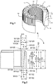
- FIGs. 1-3 shows an apparatus 1 for torsionally coupling a torque output device (not shown) and a threaded fastener (not shown) in accordance with a first embodiment.
- Apparatus 1 has a first coupling member 100: rotatably and threadedly engagable with the threaded fastener; rotatably and taperedly engagable with a second coupling member 150; and non-rotatably engagable with an action portion of the torque output device.
- Second coupling member 150 is non-rotatably engagable with a reaction portion of the torque output device.
- First coupling member 100 when rotated by the action portion of the torque output device, applies a load to the threaded fastener to close a joint (not shown).
- First coupling member 100 is an annular body and, as shown in FIGs. 1-3 , formed as a sleeve. It has an inner surface 110 with inner thread means 120 engagable with outer thread means of the threaded fastener of the joint, for example a bolt or stud. It further has an outer surface 111 with a polygonal formation 121 which is rotatably engagable with an inner surface 160 with a polygonal formation 170 of second coupling member 150. Polygonal formation 121 is shaped as an inverted frustum of a stepped cone. It further has a lower surface 113 which is rotatably engagable with inner surface 160 with polygonal formation 170 of second coupling member 150.
- FIGs. 1-3 show four external cylindrical features removed at regular length and width intervals. Note that the quantity, dimensions, geometries and intervals of removed external cylindrical features may vary depending on the application to optimize the formed coupling. Varying the quantity, dimensions, geometries and intervals from one removed external cylindrical feature to the next varies the nominal angle of polygonal formation 121. The step length may be sized infinitely small to create a smooth taper. Alternatively external portions of first coupling member 100 may be removed in one step to form a smooth conical outer surface.
- First coupling member 100 further has an upper surface 112 with a locking means 130 which may be formed by a plurality of bores extending in an axial direction and spaced for one another in a circumferential direction.
- Locking means 130 may be formed by any suitable geometry, for example castellation. Locking means 130 non-rotatably engages with the action portion of the torque output device.
- Second coupling member 150 is an annular body and, as shown in FIGs. 1-3 , formed as a sleeve. It is shaped as a hollow frustum of a stepped cone. An internal cylindrical feature is removed from second coupling member 150 at a shallow depth. Successive internal cylindrical features are removed at regular length and width intervals. Each successive feature starts where the preceding feature stops. The geometric pattern of removed internal cylindrical features continues until space restricts the addition of another internal cylindrical feature.
- FIGs. 1-3 show four internal cylindrical features removed at regular length and width intervals. Note that the quantity, dimensions, geometries and intervals of removed internal cylindrical features may vary depending on the application to optimize the formed coupling. Varying the quantity, dimensions, geometries and intervals from one removed internal cylindrical feature to the next varies the nominal angle of the conical shape these features form.
- the step length may be sized infinitely small to create a smooth taper. Alternatively internal portions of first coupling member 100 may be removed in one step to form a smooth conical inner surface.
- FIG. 2 shows dimensions of apparatus 1.
- first and second coupling members 100 and 150 L 100 and L 150
- the cross-sectional widths (W 100 and W 150 ) will be substantially similar.
- Second coupling member 150 has inner surface 160 with polygonal formation 170 rotatably engagable with outer surface 111 with polygonal formation 121 of first coupling member 100.
- Polygonal formation 170 is shaped as a frustum of a stepped cone. Inner surfaces 110 and 160 are substantially smooth.
- Second coupling member 150 further has a locking means 180 which is formed by a plurality of outer spines extending in an axial direction and spaced from one another in a circumferential direction. Locking means 180 non-rotatably engages with inner spines of the reaction portion of the torque output device.
- Second coupling member 150 further has a lower surface 163 which rests on an upper surface of the joint.
- Lower surface 163 may be substantially rough and may be made in many different ways, for example by a plurality of ridges, ripples or teeth.
- Apparatus 1 operates in the following manner. Second coupling member 150 is applied over the threaded fastener and rests on the upper surface of the joint. First coupling member 100 is applied on the threaded fastener by screwing the first coupling member 100 until its outer surface 111 is flush with inner surface 160 of second coupling member. Then, the action portion of the torque output device engages locking means 130 of first coupling member 100. The reaction portion of the torque output device engages locking means 180 of second coupling member 150. The action portion of the torque output device rotates first coupling member 100.
- first coupling member 100 slides on the smooth interface between its outer surface 111 and inner surface 160 of second coupling member; and turns around the threaded fastener, which is stretched to a predetermined load, to tighten the joint.
- second coupling member 150 embeds itself, via lower surface 163, on the upper surface of the joint; and, together with the reaction portion of the torque output device does not turn. When the threaded fastener is sufficiently stretched (tightened), the torque output device is disengaged.
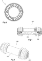
- FIGs. 4-5 show an apparatus for torsionally coupling a threaded fastener and a torque output device not belonging to the present invention.
- a conical geometry for torsional coupling of a threaded fastener and a torque output device yields a better load stress distribution.
- This embodiment introduces a low profile coupling geometry that will allow a torsion-coupling feature on the top of a stud to be formed internally by distributing stresses more evenly and therefore allowing for a more efficient packaging of the coupling features.
- a stepped 12-point hole in the top surface of the stud is used for torsion coupling with a three-piece mechanical stud-tensioning device.
- An internal 12-point feature is placed in the top of the stud at a shallow depth.
- Successive 12-point features are progressively added at smaller 12-point sizes each at shallow depths and each starting where the preceding 12-point stopped.
- the pattern of decreasing 12-point geometry will decrease until space restricts the addition of another 12 point. Varying the depth and size change from one 12-point feature to the next will increase or decrease the nominal angle of the conical shape these features form.
- a shaft with external matching features for each of the steps will allow for evenly distributed stress distribution and high torsion strength while decreasing the mass and volume of the studs.
- the 12-point feature can be substituted with any geometry that will prevent rotation between the two parts.
- the step depth can be sized infinitely small to create a smooth taper. Mixed step sizes and geometries can be used to optimize production of such a coupling.
- apparatus 1 includes a nut (first coupling member 100) as an inner sleeve and a washer (second coupling member 150) as an outer sleeve.
- the standard bolting flat surface nut and washer interface is changed.
- the torque reaction point is moved upwards, as compared to conventional three-piece fasteners.
- Apparatus of the present invention utilize the geometry of conventional three-piece fasteners, which allows for surface conditioning of the outer sleeve to prevent galling, leveraged with a conventional nut and washer arrangement, which retains radial strain such that the inner sleeve may be surface conditioned with minimal risk of fracture.
- fastener categories for example wood screws, machine screws, thread cutting machine screws, sheet metal screws, self drilling SMS, hex bolts, carriage bolts, lag bolts, socket screws, set screws, j-bolts, shoulder bolts, sex screws, mating screws, hanger bolts, etc.
- head styles for example flat, oval, pan, truss, round, hex, hex washer, slotted hex washer, socket cap, button, etc.
- drive types for example phillips and frearson, slotted, combination, socket, hex, allen, square, torx, multiple other geometries, etc.
- nut types for example hex, jam, cap, acorn, flange, square, torque lock, slotted, castle, etc.
- washer types for example flat, fender, finishing, square, dock, etc.
- thread types for example sharp V, American national, unified, metric, square, ACME
- tapeered When used in this specification and claims, the terms “tapered”, “taperedly” and variations thereof mean that the specified features, steps, quantities, dimensions, geometries and intervals may, from one end to another, either gradually, suddenly, step-wisely, and/or conically: be inconsistent, vary, narrow, diminish, decrease, get smaller, thin out, etc.
Claims (6)
- Appareil permettant de coupler un élément de fixation fileté et un dispositif de sortie de couple comprenant :- un premier élément d'accouplement (100) :pouvant être mis en prise par rotation et par vissage avec l'élément de fixation fileté,pouvant être mis en prise par rotation et par conicité avec un second élément d'accouplement (150),pouvant être mis en prise de façon non rotative avec une partie active du dispositif de sortie de couple,- le second élément d'accouplement (150) pouvant être mis en prise de façon non rotative avec une partie réactive du dispositif de sortie de couple,caractérisé en ce que
le premier élément d'accouplement (100) comporte une surface supérieure (112) équipée de moyens de blocage (130) qui peuvent être mis en prise de façon non rotative avec la partie active du dispositif de sortie de couple, et qui, lorsqu'ils sont mis en rotation par la partie active du dispositif de sortie de couple appliquent une charge sur l'élément de fixation fileté. - Appareil conforme à la revendication 1,
dans lequel la mise en prise par rotation et par conicité du premier élément d'accouplement et du second élément d'accouplement (100, 150) est réalisée sous la forme d'un tronc de cône à gradins, ou d'un tronc de cône lisse. - Appareil conforme à l'une quelconque des revendications précédentes,
dans lequel la mise en prise par rotation et par conicité du premier élément d'accouplement et du second élément d'accouplement (100, 150) est réalisée sous la forme d'un tronc de cône à gradins ayant des nombres de gradins, des dimensions, des géométries et des intervalles variables. - Appareil conforme à l'une quelconque des revendications précédentes,
dans lequel
la surface interne (110) du premier élément d'accouplement (100) vient en prise avec la surface externe de l'élément de fixation fileté,
la surface interne (160) du second élément d'accouplement (150) vient en prise avec la surface externe (111) et la surface inférieure (113) du premier élément d'accouplement (100),
la surface externe (161) du second élément d'accouplement (150) vient en prise avec la partie de réaction du dispositif de sortie de couple, et
la surface inférieure (163) du second élément d'accouplement (150) vient en prise avec une surface d'un joint devant être fermé. - Appareil conforme à l'une quelconque des revendications précédentes, dans lequel le second élément d'accouplement (150) entoure essentiellement le premier élément d'accouplement (100).
- Appareil conforme à l'une quelconque des revendications précédentes, dans lequel le dispositif de sortie de couple est un dispositif pneumatique, électrique, hydraulique ou à commande manuelle.
Applications Claiming Priority (2)
| Application Number | Priority Date | Filing Date | Title |
|---|---|---|---|
| US37001510P | 2010-08-02 | 2010-08-02 | |
| PCT/IB2011/002658 WO2012017331A2 (fr) | 2010-08-02 | 2011-08-02 | Appareil pour serrer des éléments de fixation filetés |
Publications (2)
| Publication Number | Publication Date |
|---|---|
| EP2601419A2 EP2601419A2 (fr) | 2013-06-12 |
| EP2601419B1 true EP2601419B1 (fr) | 2017-05-31 |
Family
ID=45559876
Family Applications (2)
| Application Number | Title | Priority Date | Filing Date |
|---|---|---|---|
| EP11814180.3A Active EP2601419B1 (fr) | 2010-08-02 | 2011-08-02 | Appareil pour serrer des éléments de fixation filetés |
| EP12705202.5A Active EP2598759B1 (fr) | 2010-08-02 | 2012-02-02 | Appareil de serrage d'organes de fixation filetés |
Family Applications After (1)
| Application Number | Title | Priority Date | Filing Date |
|---|---|---|---|
| EP12705202.5A Active EP2598759B1 (fr) | 2010-08-02 | 2012-02-02 | Appareil de serrage d'organes de fixation filetés |
Country Status (21)
| Country | Link |
|---|---|
| US (3) | US20130202384A1 (fr) |
| EP (2) | EP2601419B1 (fr) |
| JP (1) | JP2013539841A (fr) |
| KR (2) | KR102095849B1 (fr) |
| CN (2) | CN103168178A (fr) |
| AR (1) | AR089892A1 (fr) |
| AU (2) | AU2011287295B2 (fr) |
| BR (1) | BR112013002666B1 (fr) |
| CA (3) | CA2807350A1 (fr) |
| CL (2) | CL2013000330A1 (fr) |
| CO (2) | CO6680681A2 (fr) |
| DE (2) | DE112011102590T5 (fr) |
| EA (3) | EA201300099A1 (fr) |
| ES (1) | ES2558119T3 (fr) |
| HU (1) | HUE027346T2 (fr) |
| MX (2) | MX357042B (fr) |
| PE (2) | PE20131194A1 (fr) |
| PL (1) | PL2598759T3 (fr) |
| PT (1) | PT2598759E (fr) |
| WO (1) | WO2012017331A2 (fr) |
| ZA (2) | ZA201300890B (fr) |
Families Citing this family (16)
| Publication number | Priority date | Publication date | Assignee | Title |
|---|---|---|---|---|
| AU2014305944B2 (en) * | 2013-08-06 | 2018-07-05 | HYTORC Division Unex Corporation | Apparatus for tightening threaded fasteners |
| US20150202748A1 (en) * | 2014-01-22 | 2015-07-23 | William Michael Trudeau | System for sprinkler housing removal |
| CN104265747A (zh) * | 2014-09-15 | 2015-01-07 | 贵州航天精工制造有限公司 | 一种额定预紧力轻型螺栓连接件及其加工方法 |
| USD809883S1 (en) | 2015-01-20 | 2018-02-13 | William Michael Trudeau | Sprinkler housing removal tool |
| CN108349072B (zh) * | 2015-04-28 | 2021-08-10 | 凯特克分部尤尼克斯公司 | 反作用垫圈及其紧固套管 |
| EP3423236B1 (fr) * | 2016-03-02 | 2022-08-17 | Hytorc Division Unex Corporation | Fixation filetée comprenant des éléments augmentant le coefficient de frottement |
| WO2018160230A1 (fr) * | 2017-03-02 | 2018-09-07 | HYTORC Division Unex Corporation | Ensemble écrou à filetage conique en deux parties |
| KR101677667B1 (ko) * | 2016-03-03 | 2016-11-21 | 성산코리아 주식회사 | 관체 고정장치 |
| WO2018035264A1 (fr) * | 2016-08-16 | 2018-02-22 | HYTORC Division Unex Corporation | Appareil de fixation et/ou d'alignement d'objets |
| US10513147B1 (en) * | 2016-08-22 | 2019-12-24 | AGA Tools & Products, Inc. | Wheel lock bolt removal tool and method of use |
| CN109210060A (zh) * | 2018-09-12 | 2019-01-15 | 福建龙溪轴承(集团)股份有限公司 | 一种弹性挡圈结构和一种内外套拆装结构 |
| US11396902B2 (en) | 2019-06-20 | 2022-07-26 | The Reaction Washer Company, Llc | Engaging washers |
| WO2021013329A1 (fr) * | 2019-07-22 | 2021-01-28 | Sandvik Srp Ab | Ensemble de retenue pour une enveloppe de broyage interne d'un broyeur giratoire |
| CN110523860B (zh) * | 2019-08-22 | 2023-12-01 | 迅达(中国)电梯有限公司 | 调整工具和调整工具的使用方法 |
| US11534894B2 (en) | 2020-11-17 | 2022-12-27 | The Reaction Washer Company Llc | Socket devices and methods of use |
| CN113883153B (zh) * | 2021-10-08 | 2023-06-16 | 河南航天精工制造有限公司 | 一种降低自锁螺母锁紧力矩的方法及自锁螺母组件 |
Citations (7)
| Publication number | Priority date | Publication date | Assignee | Title |
|---|---|---|---|---|
| GB556145A (en) * | 1942-02-19 | 1943-09-22 | Frederick William Dixon | Improvements in or relating to grub screws adapted to be rotated by some form of key |
| GB2037390A (en) * | 1978-12-22 | 1980-07-09 | B & A Eng Co | Fixing device and tool therefor |
| GB2329947A (en) * | 1997-10-06 | 1999-04-07 | Harry Robinson | Stepped driving recess and driving tool for a fastener |
| GB2361043A (en) * | 2000-04-07 | 2001-10-10 | Uniscrew Ltd | Driving head for a fastener having at least two recesses |
| US20030209113A1 (en) * | 2002-05-10 | 2003-11-13 | Brooks Lawrence Antony | Integrated fastening system |
| US20050098000A1 (en) * | 2003-11-06 | 2005-05-12 | Brooks Laurence A. | Multi-tiered-recess screws |
| WO2007022293A1 (fr) * | 2005-08-17 | 2007-02-22 | Uni-Screw Worldwide, Inc. | Éléments de fixation avec empreintes à plusieurs étages et vis avec pointes de vis à plusieurs étages |
Family Cites Families (41)
| Publication number | Priority date | Publication date | Assignee | Title |
|---|---|---|---|---|
| US1389468A (en) * | 1920-07-28 | 1921-08-30 | William R White | Safety pneumatic wrench |
| US1969223A (en) * | 1933-02-16 | 1934-08-07 | Kotvis William | Lock nut |
| US2397216A (en) * | 1944-06-16 | 1946-03-26 | Domnic V Stellin | Socket head screw |
| US2908309A (en) | 1956-10-30 | 1959-10-13 | Adelaide E Brill | Threadless plastic nut having stepped bore sections |
| US3127798A (en) * | 1961-09-29 | 1964-04-07 | Michael J Gol | Telescoping inserted wrenches |
| JPS526967U (fr) * | 1975-07-01 | 1977-01-18 | ||
| US4258596A (en) * | 1978-01-18 | 1981-03-31 | Southco, Inc. | Tamper-resistant fastener |
| JPS6455410A (en) | 1987-04-16 | 1989-03-02 | Dagurasu Uorii Retsukusu | Clamping device |
| KR950014006B1 (ko) | 1990-08-17 | 1995-11-20 | 케이. 졍커스 죤 | 고정장치 |
| US5112176A (en) * | 1991-05-09 | 1992-05-12 | Mcgard, Inc. | Shrouded anti-theft locknut |
| DE4209265A1 (de) * | 1991-12-21 | 1993-06-24 | Dyckerhoff & Widmann Ag | Vorrichtung zur verankerung eines stabfoermigen zugglieds aus faserverbundwerkstoff |
| US5318397A (en) | 1992-05-07 | 1994-06-07 | Junkers John K | Mechanical tensioner |
| DE9411853U1 (de) * | 1993-11-20 | 1994-09-29 | Kloeber Johannes | Vorrichtung zur Überlastsicherung |
| GB2285940A (en) * | 1994-01-27 | 1995-08-02 | Malcolm Turner | Fastening system |
| US5640749A (en) | 1994-10-21 | 1997-06-24 | Junkers; John K. | Method of and device for elongating and relaxing a stud |
| US5622465A (en) | 1996-04-26 | 1997-04-22 | Junkers; J. K. | Lock nut |
| US6273659B1 (en) | 1997-02-17 | 2001-08-14 | Power Tool Holders Incorporated | Locking mechanism for a rotary working member |
| US5888041A (en) | 1997-10-17 | 1999-03-30 | Junkers; John K. | Lock nut |
| US6254322B1 (en) | 1998-03-03 | 2001-07-03 | John K. Junkers | Bolt with a bolt member, a washer and a sleeve for applying forces to the bolt member and the sleeve |
| US6092968A (en) * | 1998-05-29 | 2000-07-25 | Mcgard, Inc. | Fastener structure |
| US6220801B1 (en) * | 1999-02-02 | 2001-04-24 | Chung-I Lin | Free-running-on, locking-off and tension directly indicated locking nut (frolo & TDI locking nut) |
| US6435791B1 (en) * | 2000-05-19 | 2002-08-20 | Maclean-Fogg Company | Wheel fastener assemblies |
| US6461093B1 (en) * | 2000-09-05 | 2002-10-08 | John K. Junkers | Threaded fastener |
| US6948408B1 (en) * | 2001-08-17 | 2005-09-27 | Howard Lee | Flat ended double cube shaped tipped, screwdriver system |
| GB2403441B (en) * | 2001-09-17 | 2005-02-16 | Uni Screw Worldwide Inc | Method of manufacturing a cold forming punch |
| US6685412B2 (en) | 2001-10-19 | 2004-02-03 | Cross Medical Products, Inc. | Multi-lobe torque driving recess and tool in particular for an orthopedic implant screw |
| US7125213B2 (en) | 2001-12-06 | 2006-10-24 | Junkers John K | Washer, fastener provided with a washer, method of and power tool for fastening objects |
| US7066053B2 (en) * | 2002-03-29 | 2006-06-27 | Junkers John K | Washer, fastener provided with a washer |
| US7029216B2 (en) * | 2003-09-08 | 2006-04-18 | Fluidmaster, Inc. | Torque-limiting locknut |
| US7793731B2 (en) * | 2004-06-22 | 2010-09-14 | Boyd Anthony R | Entry swivel apparatus and method |
| JP2006090456A (ja) | 2004-09-24 | 2006-04-06 | Nitto Seiko Co Ltd | 駆動穴付きねじ |
| US7188554B2 (en) * | 2005-06-09 | 2007-03-13 | Atlas Spine, Inc. | Medical fastener and tool |
| US20070108402A1 (en) * | 2005-11-14 | 2007-05-17 | Jeremiah Davis | Sealed hub for motor actuated valve |
| US20070163396A1 (en) | 2006-01-17 | 2007-07-19 | Chih-Ching Hsieh | Connection device for connecting socket with pneumatic tools |
| JP4351710B2 (ja) | 2007-04-05 | 2009-10-28 | 株式会社トープラ | ビット係合穴付きねじ及び一群のビット係合穴付きねじとドライバビットとの組み合わせ |
| CN201129349Y (zh) * | 2007-07-30 | 2008-10-08 | 崔宝林 | 组合紧固断卡式防卸防盗螺母 |
| DE102007053578A1 (de) * | 2007-11-07 | 2009-05-14 | ITW Oberflächentechnik GmbH & Co. KG | Automatischer Spritzapparat für Beschichtungsflüssigkeit und seine Kombination mit einem Roboter |
| FR2930805B1 (fr) * | 2008-04-30 | 2014-11-28 | Gay Pierre | Procede et organe de serrage d'un element de visserie, dispositif de fixation et de serrage |
| JP2010054049A (ja) * | 2008-07-31 | 2010-03-11 | Katsuyuki Totsu | ボルト及びこれに適合するソケットレンチ並びにこれらの組合せ |
| US7755559B2 (en) | 2008-12-09 | 2010-07-13 | Mobile Mark, Inc. | Dual-band omnidirectional antenna |
| US8327943B2 (en) * | 2009-11-12 | 2012-12-11 | Vetco Gray Inc. | Wellhead isolation protection sleeve |
-
2011
- 2011-08-02 EP EP11814180.3A patent/EP2601419B1/fr active Active
- 2011-08-02 DE DE112011102590.4T patent/DE112011102590T5/de not_active Withdrawn
- 2011-08-02 CN CN2011800447236A patent/CN103168178A/zh active Pending
- 2011-08-02 US US13/814,226 patent/US20130202384A1/en not_active Abandoned
- 2011-08-02 BR BR112013002666-9A patent/BR112013002666B1/pt active IP Right Grant
- 2011-08-02 AU AU2011287295A patent/AU2011287295B2/en active Active
- 2011-08-02 KR KR1020137005141A patent/KR102095849B1/ko active IP Right Grant
- 2011-08-02 CA CA2807350A patent/CA2807350A1/fr not_active Abandoned
- 2011-08-02 MX MX2013001414A patent/MX357042B/es active IP Right Grant
- 2011-08-02 JP JP2013522319A patent/JP2013539841A/ja active Pending
- 2011-08-02 EA EA201300099A patent/EA201300099A1/ru unknown
- 2011-08-02 WO PCT/IB2011/002658 patent/WO2012017331A2/fr active Application Filing
-
2012
- 2012-02-02 CA CA2806867A patent/CA2806867C/fr active Active
- 2012-02-02 ES ES12705202.5T patent/ES2558119T3/es active Active
- 2012-02-02 KR KR1020137002958A patent/KR102083876B1/ko active IP Right Grant
- 2012-02-02 PE PE2013000181A patent/PE20131194A1/es active IP Right Grant
- 2012-02-02 PL PL12705202T patent/PL2598759T3/pl unknown
- 2012-02-02 CA CA3113351A patent/CA3113351A1/fr active Pending
- 2012-02-02 MX MX2013001307A patent/MX357379B/es active IP Right Grant
- 2012-02-02 DE DE112012000062T patent/DE112012000062T5/de not_active Withdrawn
- 2012-02-02 PE PE2017002774A patent/PE20190667A1/es unknown
- 2012-02-02 AU AU2013200505A patent/AU2013200505A1/en not_active Abandoned
- 2012-02-02 CN CN201280002925.9A patent/CN103119309B/zh active Active
- 2012-02-02 AR ARP130100338A patent/AR089892A1/es active IP Right Grant
- 2012-02-02 PT PT127052025T patent/PT2598759E/pt unknown
- 2012-02-02 HU HUE12705202A patent/HUE027346T2/en unknown
- 2012-02-02 EA EA201300082A patent/EA028900B1/ru not_active IP Right Cessation
- 2012-02-02 US US13/814,229 patent/US10030688B2/en active Active
- 2012-02-02 EP EP12705202.5A patent/EP2598759B1/fr active Active
- 2012-02-02 EA EA201691593A patent/EA031672B1/ru not_active IP Right Cessation
-
2013
- 2013-01-31 CL CL2013000330A patent/CL2013000330A1/es unknown
- 2013-02-01 ZA ZA2013/00890A patent/ZA201300890B/en unknown
- 2013-02-01 CL CL2013000343A patent/CL2013000343A1/es unknown
- 2013-02-08 ZA ZA2013/01078A patent/ZA201301078B/en unknown
- 2013-02-28 CO CO13040950A patent/CO6680681A2/es active IP Right Grant
-
2014
- 2014-02-27 CO CO14042280A patent/CO6890086A2/es unknown
-
2018
- 2018-03-19 US US15/924,986 patent/US20180209469A1/en not_active Abandoned
Patent Citations (7)
| Publication number | Priority date | Publication date | Assignee | Title |
|---|---|---|---|---|
| GB556145A (en) * | 1942-02-19 | 1943-09-22 | Frederick William Dixon | Improvements in or relating to grub screws adapted to be rotated by some form of key |
| GB2037390A (en) * | 1978-12-22 | 1980-07-09 | B & A Eng Co | Fixing device and tool therefor |
| GB2329947A (en) * | 1997-10-06 | 1999-04-07 | Harry Robinson | Stepped driving recess and driving tool for a fastener |
| GB2361043A (en) * | 2000-04-07 | 2001-10-10 | Uniscrew Ltd | Driving head for a fastener having at least two recesses |
| US20030209113A1 (en) * | 2002-05-10 | 2003-11-13 | Brooks Lawrence Antony | Integrated fastening system |
| US20050098000A1 (en) * | 2003-11-06 | 2005-05-12 | Brooks Laurence A. | Multi-tiered-recess screws |
| WO2007022293A1 (fr) * | 2005-08-17 | 2007-02-22 | Uni-Screw Worldwide, Inc. | Éléments de fixation avec empreintes à plusieurs étages et vis avec pointes de vis à plusieurs étages |
Also Published As
Similar Documents
| Publication | Publication Date | Title |
|---|---|---|
| EP2601419B1 (fr) | Appareil pour serrer des éléments de fixation filetés | |
| US7462007B2 (en) | Reactive biasing fasteners | |
| JP4051092B2 (ja) | 自由回転プリベリング・トルクナット | |
| JP5204856B2 (ja) | 改良されたナット及びボルト | |
| AU739703B2 (en) | Fastening device | |
| US5584626A (en) | Torque-limiting fastening element | |
| US20220016750A1 (en) | Torque-angle structural fastening system | |
| EP2688713B1 (fr) | Système de fixation structural à angle de couple | |
| EP2238359B1 (fr) | Élément de fixation de verrouillage | |
| DK2598759T3 (en) | Device for tightening threaded fasteners | |
| AU2017276291B2 (en) | Apparatus for tightening threaded fasteners | |
| JPS63502920A (ja) | 複数の工作物に対する締付方法及びこれに使用するファスナ |
Legal Events
| Date | Code | Title | Description |
|---|---|---|---|
| PUAI | Public reference made under article 153(3) epc to a published international application that has entered the european phase |
Free format text: ORIGINAL CODE: 0009012 |
|
| 17P | Request for examination filed |
Effective date: 20130301 |
|
| AK | Designated contracting states |
Kind code of ref document: A2 Designated state(s): AL AT BE BG CH CY CZ DE DK EE ES FI FR GB GR HR HU IE IS IT LI LT LU LV MC MK MT NL NO PL PT RO RS SE SI SK SM TR |
|
| DAX | Request for extension of the european patent (deleted) | ||
| 17Q | First examination report despatched |
Effective date: 20150828 |
|
| GRAP | Despatch of communication of intention to grant a patent |
Free format text: ORIGINAL CODE: EPIDOSNIGR1 |
|
| RAP1 | Party data changed (applicant data changed or rights of an application transferred) |
Owner name: JETYD CORP. |
|
| INTG | Intention to grant announced |
Effective date: 20170105 |
|
| GRAS | Grant fee paid |
Free format text: ORIGINAL CODE: EPIDOSNIGR3 |
|
| GRAA | (expected) grant |
Free format text: ORIGINAL CODE: 0009210 |
|
| AK | Designated contracting states |
Kind code of ref document: B1 Designated state(s): AL AT BE BG CH CY CZ DE DK EE ES FI FR GB GR HR HU IE IS IT LI LT LU LV MC MK MT NL NO PL PT RO RS SE SI SK SM TR |
|
| REG | Reference to a national code |
Ref country code: CH Ref legal event code: EP Ref country code: GB Ref legal event code: FG4D |
|
| REG | Reference to a national code |
Ref country code: AT Ref legal event code: REF Ref document number: 897760 Country of ref document: AT Kind code of ref document: T Effective date: 20170615 |
|
| REG | Reference to a national code |
Ref country code: IE Ref legal event code: FG4D |
|
| REG | Reference to a national code |
Ref country code: DE Ref legal event code: R096 Ref document number: 602011038413 Country of ref document: DE |
|
| REG | Reference to a national code |
Ref country code: FR Ref legal event code: PLFP Year of fee payment: 7 |
|
| REG | Reference to a national code |
Ref country code: NL Ref legal event code: MP Effective date: 20170531 |
|
| REG | Reference to a national code |
Ref country code: LT Ref legal event code: MG4D |
|
| REG | Reference to a national code |
Ref country code: AT Ref legal event code: MK05 Ref document number: 897760 Country of ref document: AT Kind code of ref document: T Effective date: 20170531 |
|
| PG25 | Lapsed in a contracting state [announced via postgrant information from national office to epo] |
Ref country code: GR Free format text: LAPSE BECAUSE OF FAILURE TO SUBMIT A TRANSLATION OF THE DESCRIPTION OR TO PAY THE FEE WITHIN THE PRESCRIBED TIME-LIMIT Effective date: 20170901 Ref country code: AT Free format text: LAPSE BECAUSE OF FAILURE TO SUBMIT A TRANSLATION OF THE DESCRIPTION OR TO PAY THE FEE WITHIN THE PRESCRIBED TIME-LIMIT Effective date: 20170531 Ref country code: ES Free format text: LAPSE BECAUSE OF FAILURE TO SUBMIT A TRANSLATION OF THE DESCRIPTION OR TO PAY THE FEE WITHIN THE PRESCRIBED TIME-LIMIT Effective date: 20170531 Ref country code: HR Free format text: LAPSE BECAUSE OF FAILURE TO SUBMIT A TRANSLATION OF THE DESCRIPTION OR TO PAY THE FEE WITHIN THE PRESCRIBED TIME-LIMIT Effective date: 20170531 Ref country code: LT Free format text: LAPSE BECAUSE OF FAILURE TO SUBMIT A TRANSLATION OF THE DESCRIPTION OR TO PAY THE FEE WITHIN THE PRESCRIBED TIME-LIMIT Effective date: 20170531 Ref country code: NO Free format text: LAPSE BECAUSE OF FAILURE TO SUBMIT A TRANSLATION OF THE DESCRIPTION OR TO PAY THE FEE WITHIN THE PRESCRIBED TIME-LIMIT Effective date: 20170831 Ref country code: FI Free format text: LAPSE BECAUSE OF FAILURE TO SUBMIT A TRANSLATION OF THE DESCRIPTION OR TO PAY THE FEE WITHIN THE PRESCRIBED TIME-LIMIT Effective date: 20170531 |
|
| PG25 | Lapsed in a contracting state [announced via postgrant information from national office to epo] |
Ref country code: NL Free format text: LAPSE BECAUSE OF FAILURE TO SUBMIT A TRANSLATION OF THE DESCRIPTION OR TO PAY THE FEE WITHIN THE PRESCRIBED TIME-LIMIT Effective date: 20170531 Ref country code: RS Free format text: LAPSE BECAUSE OF FAILURE TO SUBMIT A TRANSLATION OF THE DESCRIPTION OR TO PAY THE FEE WITHIN THE PRESCRIBED TIME-LIMIT Effective date: 20170531 Ref country code: SE Free format text: LAPSE BECAUSE OF FAILURE TO SUBMIT A TRANSLATION OF THE DESCRIPTION OR TO PAY THE FEE WITHIN THE PRESCRIBED TIME-LIMIT Effective date: 20170531 Ref country code: IS Free format text: LAPSE BECAUSE OF FAILURE TO SUBMIT A TRANSLATION OF THE DESCRIPTION OR TO PAY THE FEE WITHIN THE PRESCRIBED TIME-LIMIT Effective date: 20170930 Ref country code: BG Free format text: LAPSE BECAUSE OF FAILURE TO SUBMIT A TRANSLATION OF THE DESCRIPTION OR TO PAY THE FEE WITHIN THE PRESCRIBED TIME-LIMIT Effective date: 20170831 Ref country code: LV Free format text: LAPSE BECAUSE OF FAILURE TO SUBMIT A TRANSLATION OF THE DESCRIPTION OR TO PAY THE FEE WITHIN THE PRESCRIBED TIME-LIMIT Effective date: 20170531 |
|
| PG25 | Lapsed in a contracting state [announced via postgrant information from national office to epo] |
Ref country code: EE Free format text: LAPSE BECAUSE OF FAILURE TO SUBMIT A TRANSLATION OF THE DESCRIPTION OR TO PAY THE FEE WITHIN THE PRESCRIBED TIME-LIMIT Effective date: 20170531 Ref country code: CZ Free format text: LAPSE BECAUSE OF FAILURE TO SUBMIT A TRANSLATION OF THE DESCRIPTION OR TO PAY THE FEE WITHIN THE PRESCRIBED TIME-LIMIT Effective date: 20170531 Ref country code: DK Free format text: LAPSE BECAUSE OF FAILURE TO SUBMIT A TRANSLATION OF THE DESCRIPTION OR TO PAY THE FEE WITHIN THE PRESCRIBED TIME-LIMIT Effective date: 20170531 Ref country code: SK Free format text: LAPSE BECAUSE OF FAILURE TO SUBMIT A TRANSLATION OF THE DESCRIPTION OR TO PAY THE FEE WITHIN THE PRESCRIBED TIME-LIMIT Effective date: 20170531 Ref country code: RO Free format text: LAPSE BECAUSE OF FAILURE TO SUBMIT A TRANSLATION OF THE DESCRIPTION OR TO PAY THE FEE WITHIN THE PRESCRIBED TIME-LIMIT Effective date: 20170531 |
|
| PG25 | Lapsed in a contracting state [announced via postgrant information from national office to epo] |
Ref country code: PL Free format text: LAPSE BECAUSE OF FAILURE TO SUBMIT A TRANSLATION OF THE DESCRIPTION OR TO PAY THE FEE WITHIN THE PRESCRIBED TIME-LIMIT Effective date: 20170531 Ref country code: SM Free format text: LAPSE BECAUSE OF FAILURE TO SUBMIT A TRANSLATION OF THE DESCRIPTION OR TO PAY THE FEE WITHIN THE PRESCRIBED TIME-LIMIT Effective date: 20170531 Ref country code: IT Free format text: LAPSE BECAUSE OF FAILURE TO SUBMIT A TRANSLATION OF THE DESCRIPTION OR TO PAY THE FEE WITHIN THE PRESCRIBED TIME-LIMIT Effective date: 20170531 |
|
| REG | Reference to a national code |
Ref country code: DE Ref legal event code: R097 Ref document number: 602011038413 Country of ref document: DE |
|
| REG | Reference to a national code |
Ref country code: CH Ref legal event code: PL |
|
| PG25 | Lapsed in a contracting state [announced via postgrant information from national office to epo] |
Ref country code: MC Free format text: LAPSE BECAUSE OF FAILURE TO SUBMIT A TRANSLATION OF THE DESCRIPTION OR TO PAY THE FEE WITHIN THE PRESCRIBED TIME-LIMIT Effective date: 20170531 |
|
| PLBE | No opposition filed within time limit |
Free format text: ORIGINAL CODE: 0009261 |
|
| STAA | Information on the status of an ep patent application or granted ep patent |
Free format text: STATUS: NO OPPOSITION FILED WITHIN TIME LIMIT |
|
| PG25 | Lapsed in a contracting state [announced via postgrant information from national office to epo] |
Ref country code: CH Free format text: LAPSE BECAUSE OF NON-PAYMENT OF DUE FEES Effective date: 20170831 Ref country code: LI Free format text: LAPSE BECAUSE OF NON-PAYMENT OF DUE FEES Effective date: 20170831 |
|
| 26N | No opposition filed |
Effective date: 20180301 |
|
| REG | Reference to a national code |
Ref country code: IE Ref legal event code: MM4A |
|
| PG25 | Lapsed in a contracting state [announced via postgrant information from national office to epo] |
Ref country code: SI Free format text: LAPSE BECAUSE OF FAILURE TO SUBMIT A TRANSLATION OF THE DESCRIPTION OR TO PAY THE FEE WITHIN THE PRESCRIBED TIME-LIMIT Effective date: 20170531 |
|
| REG | Reference to a national code |
Ref country code: BE Ref legal event code: MM Effective date: 20170831 |
|
| PG25 | Lapsed in a contracting state [announced via postgrant information from national office to epo] |
Ref country code: LU Free format text: LAPSE BECAUSE OF NON-PAYMENT OF DUE FEES Effective date: 20170802 |
|
| PG25 | Lapsed in a contracting state [announced via postgrant information from national office to epo] |
Ref country code: IE Free format text: LAPSE BECAUSE OF NON-PAYMENT OF DUE FEES Effective date: 20170802 |
|
| REG | Reference to a national code |
Ref country code: FR Ref legal event code: PLFP Year of fee payment: 8 |
|
| PG25 | Lapsed in a contracting state [announced via postgrant information from national office to epo] |
Ref country code: BE Free format text: LAPSE BECAUSE OF NON-PAYMENT OF DUE FEES Effective date: 20170831 |
|
| PG25 | Lapsed in a contracting state [announced via postgrant information from national office to epo] |
Ref country code: MT Free format text: LAPSE BECAUSE OF NON-PAYMENT OF DUE FEES Effective date: 20170802 |
|
| PG25 | Lapsed in a contracting state [announced via postgrant information from national office to epo] |
Ref country code: HU Free format text: LAPSE BECAUSE OF FAILURE TO SUBMIT A TRANSLATION OF THE DESCRIPTION OR TO PAY THE FEE WITHIN THE PRESCRIBED TIME-LIMIT; INVALID AB INITIO Effective date: 20110802 |
|
| PG25 | Lapsed in a contracting state [announced via postgrant information from national office to epo] |
Ref country code: CY Free format text: LAPSE BECAUSE OF NON-PAYMENT OF DUE FEES Effective date: 20170531 |
|
| PG25 | Lapsed in a contracting state [announced via postgrant information from national office to epo] |
Ref country code: MK Free format text: LAPSE BECAUSE OF FAILURE TO SUBMIT A TRANSLATION OF THE DESCRIPTION OR TO PAY THE FEE WITHIN THE PRESCRIBED TIME-LIMIT Effective date: 20170531 |
|
| PG25 | Lapsed in a contracting state [announced via postgrant information from national office to epo] |
Ref country code: TR Free format text: LAPSE BECAUSE OF FAILURE TO SUBMIT A TRANSLATION OF THE DESCRIPTION OR TO PAY THE FEE WITHIN THE PRESCRIBED TIME-LIMIT Effective date: 20170531 |
|
| PG25 | Lapsed in a contracting state [announced via postgrant information from national office to epo] |
Ref country code: PT Free format text: LAPSE BECAUSE OF FAILURE TO SUBMIT A TRANSLATION OF THE DESCRIPTION OR TO PAY THE FEE WITHIN THE PRESCRIBED TIME-LIMIT Effective date: 20170531 |
|
| PG25 | Lapsed in a contracting state [announced via postgrant information from national office to epo] |
Ref country code: AL Free format text: LAPSE BECAUSE OF FAILURE TO SUBMIT A TRANSLATION OF THE DESCRIPTION OR TO PAY THE FEE WITHIN THE PRESCRIBED TIME-LIMIT Effective date: 20170531 |
|
| REG | Reference to a national code |
Ref country code: DE Ref legal event code: R082 Ref document number: 602011038413 Country of ref document: DE Representative=s name: WALTHER BAYER FABER PATENTANWAELTE PARTGMBB, DE |
|
| P01 | Opt-out of the competence of the unified patent court (upc) registered |
Effective date: 20230621 |
|
| PGFP | Annual fee paid to national office [announced via postgrant information from national office to epo] |
Ref country code: FR Payment date: 20230620 Year of fee payment: 13 |
|
| PGFP | Annual fee paid to national office [announced via postgrant information from national office to epo] |
Ref country code: GB Payment date: 20230608 Year of fee payment: 13 |
|
| PGFP | Annual fee paid to national office [announced via postgrant information from national office to epo] |
Ref country code: DE Payment date: 20230607 Year of fee payment: 13 |