EP2600989B1 - Building provided with a hood for drawing fumes produced in metallurgical environment - Google Patents
Building provided with a hood for drawing fumes produced in metallurgical environment Download PDFInfo
- Publication number
- EP2600989B1 EP2600989B1 EP11744093.3A EP11744093A EP2600989B1 EP 2600989 B1 EP2600989 B1 EP 2600989B1 EP 11744093 A EP11744093 A EP 11744093A EP 2600989 B1 EP2600989 B1 EP 2600989B1
- Authority
- EP
- European Patent Office
- Prior art keywords
- pipes
- building
- hood body
- walls
- main hood
- Prior art date
- Legal status (The legal status is an assumption and is not a legal conclusion. Google has not performed a legal analysis and makes no representation as to the accuracy of the status listed.)
- Active
Links
Images



Classifications
-
- F—MECHANICAL ENGINEERING; LIGHTING; HEATING; WEAPONS; BLASTING
- F24—HEATING; RANGES; VENTILATING
- F24F—AIR-CONDITIONING; AIR-HUMIDIFICATION; VENTILATION; USE OF AIR CURRENTS FOR SCREENING
- F24F7/00—Ventilation
- F24F7/02—Roof ventilation
-
- B—PERFORMING OPERATIONS; TRANSPORTING
- B08—CLEANING
- B08B—CLEANING IN GENERAL; PREVENTION OF FOULING IN GENERAL
- B08B15/00—Preventing escape of dirt or fumes from the area where they are produced; Collecting or removing dirt or fumes from that area
-
- B—PERFORMING OPERATIONS; TRANSPORTING
- B08—CLEANING
- B08B—CLEANING IN GENERAL; PREVENTION OF FOULING IN GENERAL
- B08B15/00—Preventing escape of dirt or fumes from the area where they are produced; Collecting or removing dirt or fumes from that area
- B08B15/02—Preventing escape of dirt or fumes from the area where they are produced; Collecting or removing dirt or fumes from that area using chambers or hoods covering the area
-
- C—CHEMISTRY; METALLURGY
- C21—METALLURGY OF IRON
- C21C—PROCESSING OF PIG-IRON, e.g. REFINING, MANUFACTURE OF WROUGHT-IRON OR STEEL; TREATMENT IN MOLTEN STATE OF FERROUS ALLOYS
- C21C5/00—Manufacture of carbon-steel, e.g. plain mild steel, medium carbon steel or cast steel or stainless steel
- C21C5/52—Manufacture of steel in electric furnaces
- C21C5/5294—General arrangement or layout of the electric melt shop
-
- F—MECHANICAL ENGINEERING; LIGHTING; HEATING; WEAPONS; BLASTING
- F24—HEATING; RANGES; VENTILATING
- F24F—AIR-CONDITIONING; AIR-HUMIDIFICATION; VENTILATION; USE OF AIR CURRENTS FOR SCREENING
- F24F7/00—Ventilation
- F24F7/04—Ventilation with ducting systems, e.g. by double walls; with natural circulation
-
- F—MECHANICAL ENGINEERING; LIGHTING; HEATING; WEAPONS; BLASTING
- F27—FURNACES; KILNS; OVENS; RETORTS
- F27D—DETAILS OR ACCESSORIES OF FURNACES, KILNS, OVENS OR RETORTS, IN SO FAR AS THEY ARE OF KINDS OCCURRING IN MORE THAN ONE KIND OF FURNACE
- F27D17/00—Arrangements for using waste heat; Arrangements for using, or disposing of, waste gases
- F27D17/30—Arrangements for extraction or collection of waste gases; Hoods therefor
- F27D17/304—Arrangements for extraction or collection of waste gases; Hoods therefor specially adapted for electric arc furnaces
-
- Y—GENERAL TAGGING OF NEW TECHNOLOGICAL DEVELOPMENTS; GENERAL TAGGING OF CROSS-SECTIONAL TECHNOLOGIES SPANNING OVER SEVERAL SECTIONS OF THE IPC; TECHNICAL SUBJECTS COVERED BY FORMER USPC CROSS-REFERENCE ART COLLECTIONS [XRACs] AND DIGESTS
- Y02—TECHNOLOGIES OR APPLICATIONS FOR MITIGATION OR ADAPTATION AGAINST CLIMATE CHANGE
- Y02P—CLIMATE CHANGE MITIGATION TECHNOLOGIES IN THE PRODUCTION OR PROCESSING OF GOODS
- Y02P10/00—Technologies related to metal processing
- Y02P10/20—Recycling
Definitions
- a hood for drawing fumes produced in an environment in which metal processings are performed for example, an environment receiving a metallurgical furnace, such as an arc furnace. It is a further object of the present invention a building provided with such hood.
- hoods comprise a converging conduit in which are conveyed the fumes. From the converging conduit, the fumes are conveyed in dedicated pipes for discharging them in the outer environment, before that the fumes flow in suitable processing stations, for example through dust abatement filters. In their initial portions, the pipes are located above the hood converging conduit and are coaxially with it.
- the pipes extend outside the building, suspended on the roof of the latter by a supporting structure.
- the pipes are exposed to the outer environment and to winds and are as well rather susceptible to seismic events. Therefore, they require a supporting structure adapted to support them in every environmental and weather conditions, for example with high winds or heavy rains, or with snow or seismic events. Therefore, such a supporting structure is subjected to both high static and dynamic loads, and should be dimensioned accordingly.
- the extension of the pipes on the roof of the building binds the possibility to conform the pipes themselves according to arrangements optimizing the fume fluid dynamics inside them, in other words such to reduce the flow resistances. This causes high power consumptions by the fans thrusting the fumes in the pipes.
- a building according to the preamble of claim 1 is disclosed in the document US 3,746,626 .
- a fume collecting hood comprising a converging conduit between an inlet and an outlet where the exhaust pipes comprise a wall which is formed by portions of the converging part of the hood and where the pipes extend laterally from a header chamber is disclosed in the document DE 16 04 293 A1 .
- the object of the present invention is to provide a hood for drawing fumes in a metallurgical environment such to overcome, at least partially, the problems of the cited prior art.
- a building adapted to receive a metallurgical environment that is an environment in which are performed metal processings, is shown at 1.
- the inside of building 1 can receive a metallurgical furnace 2, such as an arc furnace.
- building 1 has been schematically shown. Specifically, a possible supporting structure provided with supporting pillars 3 has been shown. In order to simplify the description, further elements of the building, such as walls, windows, etcetera, have not been expressly shown.
- the operations performed in them specifically the casting operations of the furnace 2, produce fumes which require to be taken outside the building itself and, preferably, processed, for example by suitable filters, before being expelled in the outer environment.
- the latter comprises a drawing hood 4.
- the fume drawing in the hood is preferably aided by fans (not shown in the figures).
- Hood 4 comprises a main hood body 5 having a shape suitable for the fume draft.
- the hood main body 5 delimits a conduit having an inlet opening 6 receiving the fumes coming from the metallurgical environment (located below the main hood body 5 in the normal conditions of use), and an outlet opening 7, through which the fumes exit the main hood body 5.
- the hood main body 5 has the arrangement of a converging conduit.
- the inlet opening 6 and the outlet opening 7 having a length smaller than the one of the inlet opening 6, are one over the other. Still more preferably, such inlet 6 and outlet 7 openings are aligned with respect to the furnace 2, so that to receive the fumes coming from it without causing the fumes to be subjected to substantial path changes.
- the main hood body 5 besides the above-mentioned function of drawing and conveying the fumes, has also the function of covering the building.
- it acts also as a roof for the building 1, at least in the portion in which are performed the metallurgical processings causing the fume generation.
- the hood 4 comprises a header 8 adapted to collect the fumes coming from the hood main body 5 conduit.
- the header 7 comprises a header chamber 9 in which the fumes flow when they exit the outlet opening 7 of the main hood body 5, then they are delivered to pipes 17 conveying them outside the building.
- the header 8 is coaxially arranged with respect to the hood main body 5 and, still more preferably, the header chamber 9 has an outline following the outline of the outlet opening 7 of the main hood body 5.
- the header chamber 9 and the outlet opening 7 have a square or rectangular shape.
- the outlet opening 7 of the main hood body 5 coincides with the inlet opening of the header chamber 9.
- the header 8 inlet opening there are one or more flow deflectors 10 adapted to convey the fumes from the main hood body 5 along desired paths.
- the flow deflectors 10 can be fixed or adjustable. For example, they can comprise shaped bars.
- the header 8 can comprise partitions 11 for partitioning the header chamber 9 itself in sectors.
- the partitions 11, made for example of sheet, can comprise holes or slots 23 for the partial flow of the fumes from a sector to another (for example see Figure 6 ). Alternatively, they can be devoid of such holes or slots.
- the partitions 11 can take different arrangements as a function of the path which the fumes are set to follow in the header collector. With reference to the embodiments shown in the figures, the partitions 11 can be for example shaped as plate-like panels.
- the header chamber 9 is downwardly delimited by its inlet opening, which, preferably, coincides with the outlet opening 6 of the main hood body 5.
- the header chamber 9 is laterally delimited by side closing panels 12, for example made of sheet.
- the side closing panels 12 can comprise openings for discharging the fumes in the pipes 17.
- the header chamber 9 is closed at its top, that is on the side opposite to the outlet opening 7 of the main hood body 5 conduit.
- the modes for closing the header chamber 9 can be different.
- the header chamber 9 is closed at its top by a closing panel 13, for example made of sheet, which can be connected to the side panels 12 or can be made integral with the latter.
- the hood 4 comprises an auxiliary cover 14 overlapped to the hood main body 5 in order to form a gap 15 with the latter.
- Such gap 15 substantially forms a garret, because, as said, the hood main body 5 forms a cover of the building 1.
- a portion of the auxiliary cover 14, preferably a central portion 16, closes at the top the header chamber 9.
- the terms “upper side”, “at the top”, or analogous terms mean the sides of the hood or of its components facing the side opposite to the lower side.
- the hood 4 comprises one or more pipes 17 adapted to withdraw the fumes from the header 9 and adapted to convey them outside the building 1.
- the pipes 17 can be connected to further pipes for conveying the fumes to suitable filters, in which are held the dusts before releasing the fumes in the outer environment.
- the portions of the hood main body 5 form the wall of the pipes 17.
- the pipes 17 are not separately manufactured bodies and afterwards connected to the hood, but they are integrated with it.
- the main hood body 5 has its own walls which are partially in common with the pipes.
- the main hood body 5 walls preferably defining the converging hood conduit through which the fumes are conveyed in the header 9 are at least partially in common with the pipes 17.
- Such portions of the main hood body 5 cooperate therefore with the flow of the fumes in the pipes 17.
- the main hood body 5 can be formed by a sheet (so that to delimit the above-mentioned hood conduit) shaped as a single wall. Portions of such a sheet are common to the hood conduit and pipes 17.
- the main hood body 5 can comprise a structure having one or more walls (that is formed by more overlapped layers), for example a double walls walled structure or with three or more overlapped walls.
- first walls of the more walls walled structure define the hood conduit while second walls (or their portions) of the more walls walled structure form the walls of pipes 17. Therefore, the walls of the more walls walled structure delimiting the hood conduit are not the same walls of the more walls walled structure forming the walls of pipes 17.
- the innermost walls of the double walls walled structure delimit the hood conduit, while the outermost walls of the double walls walled structure, or their portions, form the walls of pipes 17.
- the pipes 17 extend on the upper side of the main hood body 5.
- the above-mentioned portions of the main hood body 5 form the lower walls of pipes 17, which are therefore closed at the bottom by the main hood body 5.
- the pipes 17 are preferably laterally closed by two side closing panels 18, for example, made of sheet, which can be fixed to the main hood body 5.
- the side closing panels 18 can be made integral with the latter.
- the two side closing panels 18 are shaped in order to close the pipes 17 at the top during the assembly conditions. For example, they can be in the form of an inverted L or of an halfarch.
- the pipes 17 can be closed by a closing upper panel 19, which is also preferably made of sheet, opposed to the lower walls formed by the main hood body 5 (for example see Figure 2 ).
- the closing upper panel 19 can be fixed to the side closing panels 18 or it can be made integral with them.
- the closing side and upper panels 18 and 19, as well as the portions of the main hood body 5, forming the lower walls of pipes 17, are shaped so that the cross-sections of the pipes 17 are rectangular or square.
- the pipes 17 are located outside the building and directly on the upper side of the main hood body 5, and therefore they are not banked or supported by a supporting structure as it occurs with the hoods of the prior art.
- the pipes 17 are closed at the top by the above described auxiliary cover 14.
- the pipes 17 are located in the gap 15 formed by the auxiliary cover 14 and the main hood body 5 and are delimited by the latter respectively on the upper and lower sides.
- the pipes 17 are preferably closed in a way analogous to the above described one, that is by the side closing panels 18, for example having a shape plate.
- the pipes 17 are out-of-sight, as well as the header chamber 9. Therefore, they are protected from the outer environment. Also in this case, the pipes 17 have preferably a square or rectangular cross-section.
- the main hood body 5 (at least locally, in other words in its portions forming the walls for pipes 17), the side closing panels 18, the upper closing panel 19, or the auxiliary cover 14 (at least locally, in other words in its portions forming the walls for pipes 17) are made of materials adapted to withstand such load conditions. Moreover, they must be capable of resisting the aggression of dusts and chemicals contained in the fumes.
- the side and upper closing panels 18 and 19 can, to this end, have a Greek fret design, or similar, or of the sandwichtype. They can be made of materials such as steel, preferably, having protective coatings, or steels resistant to the fume high temperatures and to the corrosion (Corten steel for example), or aluminum, or light alloys.
- pipes 17 are internally provided with means (not shown in the figures) adapted to at least partially hold the dusts.
- a protective film forms in the pipes 17 due to the dust deposition, protecting the pipe themselves from wear.
- hooks are provided on the side or upper closing panels 18 or 19 or also on the portions of the hood main body 5 and/or of the auxiliary cover 14, which form the upper and lower walls of pipes 17, respectively.
- the pipes 17 comprise fume inlet openings 20 from the header chamber 9 to the pipes 17 themselves.
- Such openings 20 preferably coincide with the above-mentioned openings of the side panels 12 for connecting the header 8 to pipes 17.
- pipes 17 laterally extend from the header chamber 19.
- at least some of the pipes 17 extend from the side panels 12 of the header chamber, at which the pipes 17 inlet openings 20 are formed.
- the axes of the pipes 17 are transversally oriented to the side panels 12 themselves.
- Gates 21 can be provided at the inlet openings 20, preferably they are adjustable and adapted to choke the flow rate of the fumes in pipes 17 (for example see Figure 5 and 6 ). Extensions 24 extending inside the sectors of the header chamber 9 can be possibly provided and they are connected to the pipes 17 at the inlet openings 20 thereof.
- the side positioning of the pipes 17 with respect to the header chamber 9 enables to obtain different arrangements of the pipes system.
- the pipes 17 can be arranged in order to reduce the flow resistances of the fume inside them.
- pipes 17 are associated to only one of these side panels 12 ( Figures 1 , 4 ).
- the axes of pipes 17, according to this arrangement, are preferably perpendicular to the side panel 12 from which they extend.
- the pipes 17 are associated to three of the side panels 12.
- the pipes 17 are associated to three of the side panels 12.
- two juxtaposed pipes 17' and 17" extending from a first common side panel 12' and two further pipes 17"' and 17"" extending from a second 12" and third 12'" side panels respectively which are opposed one to the other.
- pipes 17"' and 17"" extend in a direction tangential to panels 12" and 12'" (with the axes in correspondence of the inlet openings 20 perpendicular to the first panel 12') and they are fluidically connected to the latter by intermediate communication chambers 22. These chambers are partially delimited by the side panels 12 of the header chamber 9.
- the side panels 12 can also comprise holes or slots 25.
- the inlet openings of pipes 17"' and 17"" can be also provided with gates 21.
- Pipes 17"' and 17" are connected again to the pipes 17' and 17" in the converging segment of the main hood body 5, on which they are located externally to it.
- the pipes 17 arranged in the described way partially extend outside the building by connecting to conventional pipes 26 (for example circular cross-section pipes) which supply the fumes to processing stations, for example, filters.
- Joining pipes 27 can be possibly provided between pipes 17 and conventional pipes 26, which can be also partially delimited by the main hood body 5 or by further walls of the building, or, alternatively, can be independent bodies connected to the latter.
- the hood, according to the invention, the pipes, and the main hood body are integrated one to the other.
- portions of the main hood body act also as closing walls of the pipes. In this way, it is obtained a lightweight and compact structure which subjects the building to reduced static and dynamic loads.
- the integration of the pipes to the hood causes a cost reduction of the pipes, since these are obtainable, for example, by simply applying panels on the main hood body. Therefore, it is not necessary to provide conventional pipes and complex supporting structures for the latter.
- the pipes are moderately exposed to the winds (variant having an upper closure formed by panels), or are completely protected by them (variant having an auxiliary cover).
- the pipes are integrated with hoods, they can take different arrangements, optimizing in this way the fluid dynamics of the fumes inside the pipes, in other words by reducing their flow resistances. This enables to reduce the electric energy necessary for supplying the possible fans thrusting the fumes.
- the pipes have a reduced visual impact (variant having an upper closure formed by panels) or not at all (variant having an auxiliary cover).
Landscapes
- Engineering & Computer Science (AREA)
- Chemical & Material Sciences (AREA)
- Mechanical Engineering (AREA)
- General Engineering & Computer Science (AREA)
- Combustion & Propulsion (AREA)
- Manufacturing & Machinery (AREA)
- Materials Engineering (AREA)
- Metallurgy (AREA)
- Organic Chemistry (AREA)
- Environmental & Geological Engineering (AREA)
- Waste-Gas Treatment And Other Accessory Devices For Furnaces (AREA)
- Filtering Of Dispersed Particles In Gases (AREA)
- Prevention Of Fouling (AREA)
- Building Environments (AREA)
Description
- It is an object of the present invention a hood for drawing fumes produced in an environment in which metal processings are performed, for example, an environment receiving a metallurgical furnace, such as an arc furnace. It is a further object of the present invention a building provided with such hood.
- Known hoods comprise a converging conduit in which are conveyed the fumes. From the converging conduit, the fumes are conveyed in dedicated pipes for discharging them in the outer environment, before that the fumes flow in suitable processing stations, for example through dust abatement filters. In their initial portions, the pipes are located above the hood converging conduit and are coaxially with it.
- Generally, the pipes extend outside the building, suspended on the roof of the latter by a supporting structure.
- However, the buildings provided with fume drawing systems having such arrangement have some drawbacks.
- First, the pipes are exposed to the outer environment and to winds and are as well rather susceptible to seismic events. Therefore, they require a supporting structure adapted to support them in every environmental and weather conditions, for example with high winds or heavy rains, or with snow or seismic events. Therefore, such a supporting structure is subjected to both high static and dynamic loads, and should be dimensioned accordingly.
- Moreover, the extension of the pipes on the roof of the building binds the possibility to conform the pipes themselves according to arrangements optimizing the fume fluid dynamics inside them, in other words such to reduce the flow resistances. This causes high power consumptions by the fans thrusting the fumes in the pipes.
- Lastly, the outer pipes have a substantial visual impact, which is not always acceptable.
- A building according to the preamble of
claim 1 is disclosed in the documentUS 3,746,626 . - A fume collecting hood comprising a converging conduit between an inlet and an outlet where the exhaust pipes comprise a wall which is formed by portions of the converging part of the hood and where the pipes extend laterally from a header chamber is disclosed in the
document DE 16 04 293 A1 . - Therefore, the object of the present invention is to provide a hood for drawing fumes in a metallurgical environment such to overcome, at least partially, the problems of the cited prior art.
- This and other objects are obtained by a building provided with a hood according to
claim 1. - In order to better understand and appreciate the advantages, in the following, some of its exemplifying non limiting embodiments will be described with reference to the attached drawings, wherein:
-
Figure 1 is a partially transparent schematic perspective view of a building provided with a hood according to the invention in a partially disassembled condition; -
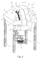
Figure 2 is a perspective schematic view of the building ofFigure 1 in a partially assembled condition according to a possible embodiment of the invention; -
Figure 3 is a perspective schematic view of the building ofFigure 1 in a partially assembled condition according to a further possible embodiment of the invention; -
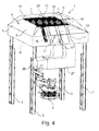
Figure 4 is a partially transparent schematic view of the building ofFigure 3 ; -
Figure 5 is a partially transparent perspective schematic view of a detail of a building provided with a hood according to a further embodiment of the invention; -
Figure 6 is a partially transparent schematic perspective view of the detail ofFigure 5 according to a further possible embodiment of the invention; -
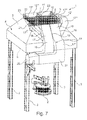
Figure 7 is a partially transparent perspective schematic view, of the building ofFigure 1 in a partially assembled condition according to a further embodiment of the invention. - With reference to the figures, a building adapted to receive a metallurgical environment, that is an environment in which are performed metal processings, is shown at 1. For example, the inside of
building 1 can receive ametallurgical furnace 2, such as an arc furnace. - It is to be observed that in the attached figures,
building 1 has been schematically shown. Specifically, a possible supporting structure provided with supportingpillars 3 has been shown. In order to simplify the description, further elements of the building, such as walls, windows, etcetera, have not been expressly shown. - In the spaces inside the
building 1, the operations performed in them, specifically the casting operations of thefurnace 2, produce fumes which require to be taken outside the building itself and, preferably, processed, for example by suitable filters, before being expelled in the outer environment. - In order to make possible the drawing and expulsion of the fumes from the inside of the
building 1, the latter comprises adrawing hood 4. The fume drawing in the hood is preferably aided by fans (not shown in the figures). - Hood 4 comprises a
main hood body 5 having a shape suitable for the fume draft. Particularly, the hoodmain body 5 delimits a conduit having an inlet opening 6 receiving the fumes coming from the metallurgical environment (located below themain hood body 5 in the normal conditions of use), and an outlet opening 7, through which the fumes exit themain hood body 5. Between the inlet opening 6 and the outlet opening 7, the hoodmain body 5 has the arrangement of a converging conduit. - Preferably, the inlet opening 6 and the outlet opening 7 having a length smaller than the one of the inlet opening 6, are one over the other. Still more preferably,
such inlet 6 andoutlet 7 openings are aligned with respect to thefurnace 2, so that to receive the fumes coming from it without causing the fumes to be subjected to substantial path changes. - Advantageously, the
main hood body 5 besides the above-mentioned function of drawing and conveying the fumes, has also the function of covering the building. In other words, it acts also as a roof for thebuilding 1, at least in the portion in which are performed the metallurgical processings causing the fume generation. - The
hood 4 comprises aheader 8 adapted to collect the fumes coming from the hoodmain body 5 conduit. Theheader 7 comprises aheader chamber 9 in which the fumes flow when they exit the outlet opening 7 of themain hood body 5, then they are delivered topipes 17 conveying them outside the building. Preferably, theheader 8 is coaxially arranged with respect to the hoodmain body 5 and, still more preferably, theheader chamber 9 has an outline following the outline of the outlet opening 7 of themain hood body 5. For example, theheader chamber 9 and the outlet opening 7 have a square or rectangular shape. - According to an embodiment, the outlet opening 7 of the
main hood body 5 coincides with the inlet opening of theheader chamber 9. - Advantageously, at the
header 8 inlet opening there are one ormore flow deflectors 10 adapted to convey the fumes from themain hood body 5 along desired paths. Theflow deflectors 10 can be fixed or adjustable. For example, they can comprise shaped bars. - The
header 8 can comprisepartitions 11 for partitioning theheader chamber 9 itself in sectors. Thepartitions 11, made for example of sheet, can comprise holes orslots 23 for the partial flow of the fumes from a sector to another (for example seeFigure 6 ). Alternatively, they can be devoid of such holes or slots. Moreover, thepartitions 11 can take different arrangements as a function of the path which the fumes are set to follow in the header collector. With reference to the embodiments shown in the figures, thepartitions 11 can be for example shaped as plate-like panels. - As said, the
header chamber 9 is downwardly delimited by its inlet opening, which, preferably, coincides with the outlet opening 6 of themain hood body 5. Preferably, theheader chamber 9 is laterally delimited byside closing panels 12, for example made of sheet. Theside closing panels 12 can comprise openings for discharging the fumes in thepipes 17. - Advantageously, the
header chamber 9 is closed at its top, that is on the side opposite to the outlet opening 7 of themain hood body 5 conduit. - The modes for closing the
header chamber 9 can be different. - According to an embodiment (
Figure 2 ), theheader chamber 9 is closed at its top by aclosing panel 13, for example made of sheet, which can be connected to theside panels 12 or can be made integral with the latter. - Alternatively, according to a further possible embodiment (
Figures 3 and4 ), thehood 4 comprises anauxiliary cover 14 overlapped to the hoodmain body 5 in order to form agap 15 with the latter.Such gap 15 substantially forms a garret, because, as said, the hoodmain body 5 forms a cover of thebuilding 1. Advantageously, according to this embodiment, a portion of theauxiliary cover 14, preferably acentral portion 16, closes at the top theheader chamber 9. - It is to be observed that in the present specification and in the attached claims, the terms "lower side", "at the bottom" or analogous terms, referred to the
hood 1 or to its components, mean a side of these facing the inside of the building, in other words facing the fume producing source, such as the metallurgical furnace. Instead, the terms "upper side", "at the top", or analogous terms mean the sides of the hood or of its components facing the side opposite to the lower side. - As said before, the
hood 4 comprises one ormore pipes 17 adapted to withdraw the fumes from theheader 9 and adapted to convey them outside thebuilding 1. For example, thepipes 17 can be connected to further pipes for conveying the fumes to suitable filters, in which are held the dusts before releasing the fumes in the outer environment. - Advantageously, the portions of the hood
main body 5 form the wall of thepipes 17. - In other words, the
pipes 17 are not separately manufactured bodies and afterwards connected to the hood, but they are integrated with it. Themain hood body 5 has its own walls which are partially in common with the pipes. - Particularly, the
main hood body 5 walls preferably defining the converging hood conduit through which the fumes are conveyed in theheader 9 are at least partially in common with thepipes 17. Such portions of themain hood body 5 cooperate therefore with the flow of the fumes in thepipes 17. For example, themain hood body 5 can be formed by a sheet (so that to delimit the above-mentioned hood conduit) shaped as a single wall. Portions of such a sheet are common to the hood conduit andpipes 17. - According to a further embodiment not shown in the figures, the
main hood body 5 can comprise a structure having one or more walls (that is formed by more overlapped layers), for example a double walls walled structure or with three or more overlapped walls. According to this arrangement, first walls of the more walls walled structure define the hood conduit while second walls (or their portions) of the more walls walled structure form the walls ofpipes 17. Therefore, the walls of the more walls walled structure delimiting the hood conduit are not the same walls of the more walls walled structure forming the walls ofpipes 17. - For example, when the
main hood body 5 is formed by a double walls walled structure, the innermost walls of the double walls walled structure delimit the hood conduit, while the outermost walls of the double walls walled structure, or their portions, form the walls ofpipes 17. - Preferably, the
pipes 17 extend on the upper side of themain hood body 5. In other words, the above-mentioned portions of themain hood body 5 form the lower walls ofpipes 17, which are therefore closed at the bottom by themain hood body 5. - The
pipes 17 are preferably laterally closed by twoside closing panels 18, for example, made of sheet, which can be fixed to themain hood body 5. Alternatively, theside closing panels 18 can be made integral with the latter. According to a further embodiment, the twoside closing panels 18 are shaped in order to close thepipes 17 at the top during the assembly conditions. For example, they can be in the form of an inverted L or of an halfarch. - At the top, the
pipes 17 can be closed by a closingupper panel 19, which is also preferably made of sheet, opposed to the lower walls formed by the main hood body 5 (for example seeFigure 2 ). The closingupper panel 19 can be fixed to theside closing panels 18 or it can be made integral with them. Preferably, the closing side andupper panels main hood body 5, forming the lower walls ofpipes 17, are shaped so that the cross-sections of thepipes 17 are rectangular or square. - According to this arrangement, the
pipes 17 are located outside the building and directly on the upper side of themain hood body 5, and therefore they are not banked or supported by a supporting structure as it occurs with the hoods of the prior art. - According to an alternative embodiment (
Figures 3 and4 ), thepipes 17 are closed at the top by the above describedauxiliary cover 14. According to this embodiment, thepipes 17 are located in thegap 15 formed by theauxiliary cover 14 and themain hood body 5 and are delimited by the latter respectively on the upper and lower sides. Laterally, thepipes 17 are preferably closed in a way analogous to the above described one, that is by theside closing panels 18, for example having a shape plate. - According to this arrangement, the
pipes 17 are out-of-sight, as well as theheader chamber 9. Therefore, they are protected from the outer environment. Also in this case, thepipes 17 have preferably a square or rectangular cross-section. - It is to be observed that, during the normal conditions of use, the
pipes 17 are vacuum-operated. Therefore, the main hood body 5 (at least locally, in other words in its portions forming the walls for pipes 17), theside closing panels 18, theupper closing panel 19, or the auxiliary cover 14 (at least locally, in other words in its portions forming the walls for pipes 17) are made of materials adapted to withstand such load conditions. Moreover, they must be capable of resisting the aggression of dusts and chemicals contained in the fumes. - The side and
upper closing panels 18 and 19 (if they are provided) can, to this end, have a Greek fret design, or similar, or of the sandwichtype. They can be made of materials such as steel, preferably, having protective coatings, or steels resistant to the fume high temperatures and to the corrosion (Corten steel for example), or aluminum, or light alloys. - According to a possible embodiment,
pipes 17 are internally provided with means (not shown in the figures) adapted to at least partially hold the dusts. For this reason, during the use, a protective film forms in thepipes 17 due to the dust deposition, protecting the pipe themselves from wear. For example, hooks are provided on the side orupper closing panels main body 5 and/or of theauxiliary cover 14, which form the upper and lower walls ofpipes 17, respectively. - The
pipes 17 comprisefume inlet openings 20 from theheader chamber 9 to thepipes 17 themselves.Such openings 20 preferably coincide with the above-mentioned openings of theside panels 12 for connecting theheader 8 topipes 17. - Advantageously,
pipes 17 laterally extend from theheader chamber 19. Particularly, according to a possible embodiment, at least some of thepipes 17 extend from theside panels 12 of the header chamber, at which thepipes 17inlet openings 20 are formed. In other words, at theside panels 12, the axes of thepipes 17 are transversally oriented to theside panels 12 themselves. -
Gates 21 can be provided at theinlet openings 20, preferably they are adjustable and adapted to choke the flow rate of the fumes in pipes 17 (for example seeFigure 5 and 6 ). Extensions 24 extending inside the sectors of theheader chamber 9 can be possibly provided and they are connected to thepipes 17 at theinlet openings 20 thereof. - The side positioning of the
pipes 17 with respect to theheader chamber 9 enables to obtain different arrangements of the pipes system. Particularly, thepipes 17 can be arranged in order to reduce the flow resistances of the fume inside them. - According to an embodiment,
pipes 17 are associated to only one of these side panels 12 (Figures 1 ,4 ). For example, it is possible to provide two juxtaposedpipes 17' and 17" extending from thesame side panel 12. The axes ofpipes 17, according to this arrangement, are preferably perpendicular to theside panel 12 from which they extend. - According to a further possible embodiment (
Figure 7 ), thepipes 17 are associated to three of theside panels 12. For example, it is possible to provide, as in the preceding example, two juxtaposedpipes 17' and 17" extending from a first common side panel 12' and twofurther pipes 17"' and 17"" extending from a second 12" and third 12'" side panels respectively which are opposed one to the other. Preferably,pipes 17"' and 17"" extend in a direction tangential topanels 12" and 12'" (with the axes in correspondence of theinlet openings 20 perpendicular to the first panel 12') and they are fluidically connected to the latter byintermediate communication chambers 22. These chambers are partially delimited by theside panels 12 of theheader chamber 9. Moreover, they can be closed by further panels or, alternatively, by theauxiliary cover 14. In order to enable the fume flow in theintermediate communication chambers 22, theside panels 12 can also comprise holes orslots 25. The inlet openings ofpipes 17"' and 17"" can be also provided withgates 21.Pipes 17"' and 17"", according to a possible embodiment, are connected again to thepipes 17' and 17" in the converging segment of themain hood body 5, on which they are located externally to it. - According to an embodiment, the
pipes 17 arranged in the described way partially extend outside the building by connecting to conventional pipes 26 (for example circular cross-section pipes) which supply the fumes to processing stations, for example, filters. Joiningpipes 27 can be possibly provided betweenpipes 17 andconventional pipes 26, which can be also partially delimited by themain hood body 5 or by further walls of the building, or, alternatively, can be independent bodies connected to the latter. - From the above given description, the person skilled in the art will appreciate that the hood, according to the invention, the pipes, and the main hood body are integrated one to the other. In fact, portions of the main hood body act also as closing walls of the pipes. In this way, it is obtained a lightweight and compact structure which subjects the building to reduced static and dynamic loads.
- Further, the integration of the pipes to the hood causes a cost reduction of the pipes, since these are obtainable, for example, by simply applying panels on the main hood body. Therefore, it is not necessary to provide conventional pipes and complex supporting structures for the latter.
- Further, the pipes are moderately exposed to the winds (variant having an upper closure formed by panels), or are completely protected by them (variant having an auxiliary cover).
- Moreover, since the pipes are integrated with hoods, they can take different arrangements, optimizing in this way the fluid dynamics of the fumes inside the pipes, in other words by reducing their flow resistances. This enables to reduce the electric energy necessary for supplying the possible fans thrusting the fumes.
- Lastly, in the hood, according to the invention, the pipes have a reduced visual impact (variant having an upper closure formed by panels) or not at all (variant having an auxiliary cover).
- To the described embodiments of the hood and building provided with such hood, the person skilled in the art, in order to satisfy existent contingent specifications, can make several additions, changes, or substitutions of elements with other operatively equivalent, without departing from the scope of the attached claims.
Claims (15)
- Building suitable to house a metallurgical environment, comprising a hood (4) for drawing fumes produced in said metallurgical environment, said hood comprising:- a main hood body (5) defining a hood conduit, said main hood body (5) having an arrangement of a converging conduit between an inlet (6) and an outlet openings (7) for the fumes coming from the metallurgical environment, wherein said outlet opening (7) lies over said inlet opening (6);- a header (8) for collecting fumes coming from the outlet opening (7) of the main hood body (5) comprising a header chamber (9);- one or more pipes (17) for conveying fumes outside said header (8),wherein said main hood body (5) forms a covering of said building (1),
characterised in that one or more portions of said main hood body (5) forming said converging conduit form a wall of said one or more pipes (17), respectively, wherein said pipes (17) laterally extend from the header chamber (9). - Building (1) according to claim 1, wherein said portions of the main hood body (5) form common to said hood conduit and to said one or more pipes (17).
- Building (1) according to claim 1, wherein said main hood body (5) comprises a two or more walled wall structure, wherein first walls of said two or more walls wall structure delimit said hood conduit, and wherein second walls of said two or more walls wall structure or portions thereof delimit said walls of the one or more pipes (17).
- Building (1) according to anyone of the preceding claims, wherein said portions of the main hood body (5) form lower walls of said one or more pipes (17).
- Building (1) according to anyone of the preceding claims, wherein said one or more pipes (17) are laterally delimited by a first and second side panels (18).
- Building (1) according to anyone of the preceding claims, wherein said header chamber (9) is closed at the top by a closing panel (13).
- Building (1) according to claim 5 or 6, wherein said one or more pipes (17) are delimited at the top by a closing upper panel (19) opposed to said main hood body (5) portions, said upper closing panel (19) being connected to said side panels (18) or being integrally made with them.
- Building (1) according to claim 5 or 6, wherein said side panels (18) are shaped so that to close at the top said pipes (17).
- Building (1) according to anyone of claims 1-5, comprising an auxiliary cover (14) overlapping the main hood body (4), delimiting with the latter a gap (15) in which said one or more pipes (17) are at least partially received.
- Building (1) according to the preceding claim, wherein portions (16) of the auxiliary cover (14) opposed to said main hood body (5) portions form upper walls of said one or more pipes (17).
- Building (1) according to claim 9 or 10, wherein said header chamber (9) is closed at the top by said auxiliary cover (14).
- Building (1) according to anyone of the preceding claims, wherein the header chamber (9) has an outline following the outline of the outlet opening (7) of the main hood body (5).
- Building (1) according to anyone of the preceding claims, wherein the header chamber (9) comprises an inlet opening which coincides with the outlet opening (7) of the main hood body (5) and one or more fixed or adjustable flow deflectors (10) adapted to convey the fumes from the main hood body (5) along desired paths.
- Building (1) according to anyone of the preceding claims, wherein said header (8) comprises partitions (11) for partitioning the header chamber (9) in sectors.
- Building (1) according to anyone of the preceding claims, wherein said pipes (17) internally comprise hooks adapted to at least partially hold fumes dusts.
Applications Claiming Priority (2)
| Application Number | Priority Date | Filing Date | Title |
|---|---|---|---|
| IT001478A ITMI20101478A1 (en) | 2010-08-03 | 2010-08-03 | HOOD FOR THE ASPIRATION OF FUMES PRODUCED IN A METALLURGICAL ENVIRONMENT AND BUILDING EQUIPPED WITH SUCH A HOOD |
| PCT/IB2011/053084 WO2012017341A1 (en) | 2010-08-03 | 2011-07-11 | Building provided with a hood for drawing fumes produced in metallurgical environment |
Publications (2)
| Publication Number | Publication Date |
|---|---|
| EP2600989A1 EP2600989A1 (en) | 2013-06-12 |
| EP2600989B1 true EP2600989B1 (en) | 2014-10-08 |
Family
ID=43661368
Family Applications (1)
| Application Number | Title | Priority Date | Filing Date |
|---|---|---|---|
| EP11744093.3A Active EP2600989B1 (en) | 2010-08-03 | 2011-07-11 | Building provided with a hood for drawing fumes produced in metallurgical environment |
Country Status (6)
| Country | Link |
|---|---|
| US (1) | US20130122798A1 (en) |
| EP (1) | EP2600989B1 (en) |
| BR (1) | BR112013002723A2 (en) |
| ES (1) | ES2525166T3 (en) |
| IT (1) | ITMI20101478A1 (en) |
| WO (1) | WO2012017341A1 (en) |
Families Citing this family (4)
| Publication number | Priority date | Publication date | Assignee | Title |
|---|---|---|---|---|
| USD783798S1 (en) * | 2014-09-30 | 2017-04-11 | Sumitomo Metal Mining Co., Ltd. | Smoke exhaust hood for a tilting furnace |
| USD755362S1 (en) * | 2014-10-23 | 2016-05-03 | Foremost Groups, Inc. | Ventilator hood |
| CO2019002734A1 (en) * | 2019-03-26 | 2019-09-30 | Cadavid Cristian Mauricio Pabon | Capture module, for extraction of gases and gaseous residues at variable temperature |
| CN120714990B (en) * | 2025-08-28 | 2025-11-07 | 沈阳博宇科技有限责任公司 | Movable dust collection and purification device for aluminum electrolysis workshop |
Family Cites Families (15)
| Publication number | Priority date | Publication date | Assignee | Title |
|---|---|---|---|---|
| DE1604293C3 (en) * | 1966-12-21 | 1973-10-18 | Siemens Electrogeraete Gmbh, 1000 Berlin Und 8000 Muenchen | Extractor hood |
| US3722182A (en) * | 1970-05-14 | 1973-03-27 | J Gilbertson | Air purifying and deodorizing device for automobiles |
| US3844901A (en) * | 1973-03-19 | 1974-10-29 | Great Lakes Carbon Corp | Coke oven emission control system |
| DE2601264A1 (en) * | 1976-01-15 | 1977-07-21 | Ind Clean Air Inc | Ventilation device for buildings with hot waste gas source - has series of open ended chambers around periphery of offtake hood to allow incoming blast of cool air from outside building |
| US4098008A (en) * | 1976-11-08 | 1978-07-04 | Wellons, Inc. | Dry kiln having bidirectional air flow with unidirectional fan rotation |
| US4109433A (en) * | 1977-07-13 | 1978-08-29 | Maze Perry V | Below roof ventilator |
| US4330372A (en) * | 1981-05-29 | 1982-05-18 | National Steel Corporation | Coke oven emission control method and apparatus |
| US4360404A (en) * | 1982-01-18 | 1982-11-23 | Koppers Company, Inc. | Apparatus for control of coke oven emissions |
| US6723145B2 (en) * | 2002-01-02 | 2004-04-20 | Dürr Industries, Inc. | Open powder booth collection design |
| KR100617079B1 (en) * | 2005-02-07 | 2006-08-30 | 엘지전자 주식회사 | Air cleaning and ventilation system |
| KR100594581B1 (en) * | 2005-03-29 | 2006-06-30 | 삼성광주전자 주식회사 | Multi Dust Collector |
| DE202006003723U1 (en) * | 2005-10-07 | 2006-06-08 | Rosconi-Metallwarenfabrik Gmbh | Smoking station with shade-type cover (4) over a tube-shaped sucking out device with air suction hole, air draft and air filter useful for smokers has double plate acrylic glass hollow chamber and avoids sideways drifting of smoke |
| US20070213003A1 (en) * | 2006-03-09 | 2007-09-13 | Building Materials Investment Corporation | Powered ridge ventilation system and method |
| US20090253364A1 (en) * | 2008-04-07 | 2009-10-08 | Mark Henry | Rechargeable fire containment and smoke extraction system |
| FR2939870B1 (en) * | 2008-12-17 | 2013-06-07 | Fondis Sa | SMOKE BOX FOR A SOLID FUEL DOMESTIC HEATING APPARATUS |
-
2010
- 2010-08-03 IT IT001478A patent/ITMI20101478A1/en unknown
-
2011
- 2011-07-11 WO PCT/IB2011/053084 patent/WO2012017341A1/en not_active Ceased
- 2011-07-11 EP EP11744093.3A patent/EP2600989B1/en active Active
- 2011-07-11 ES ES11744093.3T patent/ES2525166T3/en active Active
- 2011-07-11 US US13/811,848 patent/US20130122798A1/en not_active Abandoned
- 2011-07-11 BR BR112013002723A patent/BR112013002723A2/en not_active IP Right Cessation
Also Published As
| Publication number | Publication date |
|---|---|
| WO2012017341A1 (en) | 2012-02-09 |
| US20130122798A1 (en) | 2013-05-16 |
| BR112013002723A2 (en) | 2016-05-31 |
| ITMI20101478A1 (en) | 2012-02-04 |
| EP2600989A1 (en) | 2013-06-12 |
| ES2525166T3 (en) | 2014-12-18 |
Similar Documents
| Publication | Publication Date | Title |
|---|---|---|
| JP4852534B2 (en) | Steel exchanger system | |
| US20130122798A1 (en) | Building provided with a hood for drawing fumes produced in metallurgical environment | |
| US20100279597A1 (en) | Building circulation system using curtain wall as ventilator | |
| US10450721B2 (en) | Construction machine | |
| US20100301638A1 (en) | Integrated Air Intake System | |
| CN205736880U (en) | Vehicle | |
| CN104533840B (en) | Axial air incoming enclosure of axial-flow compressor | |
| EP2649394B1 (en) | Apparatus for conveying and pre-heating a metal charge for a melting plant | |
| CN205744132U (en) | A kind of sand-proof generating set | |
| CN202824992U (en) | Wave resistance device of explosive welding air blast wave | |
| JP5567918B2 (en) | Liner plate vertical canopy mounting structure and mounting method | |
| RU2369640C1 (en) | Facility for recovery of non-defined emissions from metallurgic installation | |
| CN109028976A (en) | Refrigerating device for materials | |
| CN102150004B (en) | Sootblower with modular canopy | |
| JP5875942B2 (en) | Radioactive material storage facility | |
| CN102700621B (en) | Engine hood and construction machinery including the engine hood | |
| RU2662762C1 (en) | Method of emissions from converter capturing and device for emissions from converter capturing | |
| CN208632581U (en) | A kind of split type furnace shell slag trap, skimming device and the converter with the skimming device | |
| US9816702B2 (en) | Waste feed device | |
| CZ307908B6 (en) | Multifunctional mobile mono-block container for a complete heat pump system linked to a transport platform | |
| CN222809496U (en) | A dust removal system on the top of a high-rise frame in a converter steelmaking workshop | |
| CN217152120U (en) | Skid-mounted structure of generator | |
| JP6318060B2 (en) | Engine system | |
| RU2484378C1 (en) | Combustion method of wood wastes, and heat generator for its implementation with heater and heat exchange chamber and cover plate of combustion chamber | |
| WO2013009177A1 (en) | Improved diverter damper |
Legal Events
| Date | Code | Title | Description |
|---|---|---|---|
| PUAI | Public reference made under article 153(3) epc to a published international application that has entered the european phase |
Free format text: ORIGINAL CODE: 0009012 |
|
| 17P | Request for examination filed |
Effective date: 20121221 |
|
| AK | Designated contracting states |
Kind code of ref document: A1 Designated state(s): AL AT BE BG CH CY CZ DE DK EE ES FI FR GB GR HR HU IE IS IT LI LT LU LV MC MK MT NL NO PL PT RO RS SE SI SK SM TR |
|
| DAX | Request for extension of the european patent (deleted) | ||
| RIC1 | Information provided on ipc code assigned before grant |
Ipc: B08B 15/00 20060101ALI20140619BHEP Ipc: F27D 17/00 20060101ALI20140619BHEP Ipc: F24F 7/04 20060101ALI20140619BHEP Ipc: C21C 5/52 20060101ALI20140619BHEP Ipc: F24F 7/02 20060101ALI20140619BHEP Ipc: B08B 15/02 20060101AFI20140619BHEP |
|
| GRAP | Despatch of communication of intention to grant a patent |
Free format text: ORIGINAL CODE: EPIDOSNIGR1 |
|
| INTG | Intention to grant announced |
Effective date: 20140806 |
|
| GRAS | Grant fee paid |
Free format text: ORIGINAL CODE: EPIDOSNIGR3 |
|
| GRAA | (expected) grant |
Free format text: ORIGINAL CODE: 0009210 |
|
| AK | Designated contracting states |
Kind code of ref document: B1 Designated state(s): AL AT BE BG CH CY CZ DE DK EE ES FI FR GB GR HR HU IE IS IT LI LT LU LV MC MK MT NL NO PL PT RO RS SE SI SK SM TR |
|
| REG | Reference to a national code |
Ref country code: GB Ref legal event code: FG4D |
|
| REG | Reference to a national code |
Ref country code: AT Ref legal event code: REF Ref document number: 690314 Country of ref document: AT Kind code of ref document: T Effective date: 20141015 Ref country code: CH Ref legal event code: EP |
|
| REG | Reference to a national code |
Ref country code: IE Ref legal event code: FG4D |
|
| REG | Reference to a national code |
Ref country code: DE Ref legal event code: R096 Ref document number: 602011010455 Country of ref document: DE Effective date: 20141120 |
|
| REG | Reference to a national code |
Ref country code: DE Ref legal event code: R082 Ref document number: 602011010455 Country of ref document: DE Representative=s name: STOLMAR & PARTNER PATENTANWAELTE PARTG MBB, DE Ref country code: DE Ref legal event code: R082 Ref document number: 602011010455 Country of ref document: DE Representative=s name: PATENTANWAELTE STOLMAR & PARTNER, DE |
|
| REG | Reference to a national code |
Ref country code: ES Ref legal event code: FG2A Ref document number: 2525166 Country of ref document: ES Kind code of ref document: T3 Effective date: 20141218 |
|
| RAP2 | Party data changed (patent owner data changed or rights of a patent transferred) |
Owner name: SMS CONCAST ITALIA S.P.A. |
|
| REG | Reference to a national code |
Ref country code: CH Ref legal event code: NV Representative=s name: RENTSCH PARTNER AG, CH |
|
| REG | Reference to a national code |
Ref country code: NL Ref legal event code: VDEP Effective date: 20141008 |
|
| REG | Reference to a national code |
Ref country code: LT Ref legal event code: MG4D |
|
| PG25 | Lapsed in a contracting state [announced via postgrant information from national office to epo] |
Ref country code: NL Free format text: LAPSE BECAUSE OF FAILURE TO SUBMIT A TRANSLATION OF THE DESCRIPTION OR TO PAY THE FEE WITHIN THE PRESCRIBED TIME-LIMIT Effective date: 20141008 |
|
| PG25 | Lapsed in a contracting state [announced via postgrant information from national office to epo] |
Ref country code: LT Free format text: LAPSE BECAUSE OF FAILURE TO SUBMIT A TRANSLATION OF THE DESCRIPTION OR TO PAY THE FEE WITHIN THE PRESCRIBED TIME-LIMIT Effective date: 20141008 Ref country code: PT Free format text: LAPSE BECAUSE OF FAILURE TO SUBMIT A TRANSLATION OF THE DESCRIPTION OR TO PAY THE FEE WITHIN THE PRESCRIBED TIME-LIMIT Effective date: 20150209 Ref country code: FI Free format text: LAPSE BECAUSE OF FAILURE TO SUBMIT A TRANSLATION OF THE DESCRIPTION OR TO PAY THE FEE WITHIN THE PRESCRIBED TIME-LIMIT Effective date: 20141008 Ref country code: NO Free format text: LAPSE BECAUSE OF FAILURE TO SUBMIT A TRANSLATION OF THE DESCRIPTION OR TO PAY THE FEE WITHIN THE PRESCRIBED TIME-LIMIT Effective date: 20150108 Ref country code: IS Free format text: LAPSE BECAUSE OF FAILURE TO SUBMIT A TRANSLATION OF THE DESCRIPTION OR TO PAY THE FEE WITHIN THE PRESCRIBED TIME-LIMIT Effective date: 20150208 |
|
| PG25 | Lapsed in a contracting state [announced via postgrant information from national office to epo] |
Ref country code: LV Free format text: LAPSE BECAUSE OF FAILURE TO SUBMIT A TRANSLATION OF THE DESCRIPTION OR TO PAY THE FEE WITHIN THE PRESCRIBED TIME-LIMIT Effective date: 20141008 Ref country code: GR Free format text: LAPSE BECAUSE OF FAILURE TO SUBMIT A TRANSLATION OF THE DESCRIPTION OR TO PAY THE FEE WITHIN THE PRESCRIBED TIME-LIMIT Effective date: 20150109 Ref country code: HR Free format text: LAPSE BECAUSE OF FAILURE TO SUBMIT A TRANSLATION OF THE DESCRIPTION OR TO PAY THE FEE WITHIN THE PRESCRIBED TIME-LIMIT Effective date: 20141008 Ref country code: PL Free format text: LAPSE BECAUSE OF FAILURE TO SUBMIT A TRANSLATION OF THE DESCRIPTION OR TO PAY THE FEE WITHIN THE PRESCRIBED TIME-LIMIT Effective date: 20141008 Ref country code: SE Free format text: LAPSE BECAUSE OF FAILURE TO SUBMIT A TRANSLATION OF THE DESCRIPTION OR TO PAY THE FEE WITHIN THE PRESCRIBED TIME-LIMIT Effective date: 20141008 Ref country code: RS Free format text: LAPSE BECAUSE OF FAILURE TO SUBMIT A TRANSLATION OF THE DESCRIPTION OR TO PAY THE FEE WITHIN THE PRESCRIBED TIME-LIMIT Effective date: 20141008 Ref country code: CY Free format text: LAPSE BECAUSE OF FAILURE TO SUBMIT A TRANSLATION OF THE DESCRIPTION OR TO PAY THE FEE WITHIN THE PRESCRIBED TIME-LIMIT Effective date: 20141008 |
|
| REG | Reference to a national code |
Ref country code: DE Ref legal event code: R097 Ref document number: 602011010455 Country of ref document: DE |
|
| PG25 | Lapsed in a contracting state [announced via postgrant information from national office to epo] |
Ref country code: DK Free format text: LAPSE BECAUSE OF FAILURE TO SUBMIT A TRANSLATION OF THE DESCRIPTION OR TO PAY THE FEE WITHIN THE PRESCRIBED TIME-LIMIT Effective date: 20141008 Ref country code: EE Free format text: LAPSE BECAUSE OF FAILURE TO SUBMIT A TRANSLATION OF THE DESCRIPTION OR TO PAY THE FEE WITHIN THE PRESCRIBED TIME-LIMIT Effective date: 20141008 Ref country code: RO Free format text: LAPSE BECAUSE OF FAILURE TO SUBMIT A TRANSLATION OF THE DESCRIPTION OR TO PAY THE FEE WITHIN THE PRESCRIBED TIME-LIMIT Effective date: 20141008 Ref country code: CZ Free format text: LAPSE BECAUSE OF FAILURE TO SUBMIT A TRANSLATION OF THE DESCRIPTION OR TO PAY THE FEE WITHIN THE PRESCRIBED TIME-LIMIT Effective date: 20141008 Ref country code: SK Free format text: LAPSE BECAUSE OF FAILURE TO SUBMIT A TRANSLATION OF THE DESCRIPTION OR TO PAY THE FEE WITHIN THE PRESCRIBED TIME-LIMIT Effective date: 20141008 |
|
| PLBE | No opposition filed within time limit |
Free format text: ORIGINAL CODE: 0009261 |
|
| STAA | Information on the status of an ep patent application or granted ep patent |
Free format text: STATUS: NO OPPOSITION FILED WITHIN TIME LIMIT |
|
| 26N | No opposition filed |
Effective date: 20150709 |
|
| PG25 | Lapsed in a contracting state [announced via postgrant information from national office to epo] |
Ref country code: MC Free format text: LAPSE BECAUSE OF FAILURE TO SUBMIT A TRANSLATION OF THE DESCRIPTION OR TO PAY THE FEE WITHIN THE PRESCRIBED TIME-LIMIT Effective date: 20141008 Ref country code: SI Free format text: LAPSE BECAUSE OF FAILURE TO SUBMIT A TRANSLATION OF THE DESCRIPTION OR TO PAY THE FEE WITHIN THE PRESCRIBED TIME-LIMIT Effective date: 20141008 |
|
| GBPC | Gb: european patent ceased through non-payment of renewal fee |
Effective date: 20150711 |
|
| PG25 | Lapsed in a contracting state [announced via postgrant information from national office to epo] |
Ref country code: LU Free format text: LAPSE BECAUSE OF FAILURE TO SUBMIT A TRANSLATION OF THE DESCRIPTION OR TO PAY THE FEE WITHIN THE PRESCRIBED TIME-LIMIT Effective date: 20150711 |
|
| REG | Reference to a national code |
Ref country code: IE Ref legal event code: MM4A |
|
| PG25 | Lapsed in a contracting state [announced via postgrant information from national office to epo] |
Ref country code: GB Free format text: LAPSE BECAUSE OF NON-PAYMENT OF DUE FEES Effective date: 20150711 |
|
| REG | Reference to a national code |
Ref country code: FR Ref legal event code: ST Effective date: 20160331 |
|
| PG25 | Lapsed in a contracting state [announced via postgrant information from national office to epo] |
Ref country code: FR Free format text: LAPSE BECAUSE OF NON-PAYMENT OF DUE FEES Effective date: 20150731 |
|
| PG25 | Lapsed in a contracting state [announced via postgrant information from national office to epo] |
Ref country code: IE Free format text: LAPSE BECAUSE OF NON-PAYMENT OF DUE FEES Effective date: 20150711 |
|
| PG25 | Lapsed in a contracting state [announced via postgrant information from national office to epo] |
Ref country code: MT Free format text: LAPSE BECAUSE OF FAILURE TO SUBMIT A TRANSLATION OF THE DESCRIPTION OR TO PAY THE FEE WITHIN THE PRESCRIBED TIME-LIMIT Effective date: 20141008 |
|
| PG25 | Lapsed in a contracting state [announced via postgrant information from national office to epo] |
Ref country code: SM Free format text: LAPSE BECAUSE OF FAILURE TO SUBMIT A TRANSLATION OF THE DESCRIPTION OR TO PAY THE FEE WITHIN THE PRESCRIBED TIME-LIMIT Effective date: 20141008 Ref country code: HU Free format text: LAPSE BECAUSE OF FAILURE TO SUBMIT A TRANSLATION OF THE DESCRIPTION OR TO PAY THE FEE WITHIN THE PRESCRIBED TIME-LIMIT; INVALID AB INITIO Effective date: 20110711 Ref country code: BG Free format text: LAPSE BECAUSE OF FAILURE TO SUBMIT A TRANSLATION OF THE DESCRIPTION OR TO PAY THE FEE WITHIN THE PRESCRIBED TIME-LIMIT Effective date: 20141008 |
|
| PG25 | Lapsed in a contracting state [announced via postgrant information from national office to epo] |
Ref country code: BE Free format text: LAPSE BECAUSE OF FAILURE TO SUBMIT A TRANSLATION OF THE DESCRIPTION OR TO PAY THE FEE WITHIN THE PRESCRIBED TIME-LIMIT Effective date: 20141008 |
|
| REG | Reference to a national code |
Ref country code: CH Ref legal event code: PCAR Free format text: NEW ADDRESS: BELLERIVESTRASSE 203 POSTFACH, 8034 ZUERICH (CH) |
|
| PG25 | Lapsed in a contracting state [announced via postgrant information from national office to epo] |
Ref country code: MK Free format text: LAPSE BECAUSE OF FAILURE TO SUBMIT A TRANSLATION OF THE DESCRIPTION OR TO PAY THE FEE WITHIN THE PRESCRIBED TIME-LIMIT Effective date: 20141008 |
|
| PG25 | Lapsed in a contracting state [announced via postgrant information from national office to epo] |
Ref country code: AL Free format text: LAPSE BECAUSE OF FAILURE TO SUBMIT A TRANSLATION OF THE DESCRIPTION OR TO PAY THE FEE WITHIN THE PRESCRIBED TIME-LIMIT Effective date: 20141008 |
|
| PGFP | Annual fee paid to national office [announced via postgrant information from national office to epo] |
Ref country code: BE Payment date: 20180730 Year of fee payment: 8 |
|
| REG | Reference to a national code |
Ref country code: CH Ref legal event code: PL |
|
| PG25 | Lapsed in a contracting state [announced via postgrant information from national office to epo] |
Ref country code: CH Free format text: LAPSE BECAUSE OF NON-PAYMENT OF DUE FEES Effective date: 20190731 Ref country code: LI Free format text: LAPSE BECAUSE OF NON-PAYMENT OF DUE FEES Effective date: 20190731 |
|
| P01 | Opt-out of the competence of the unified patent court (upc) registered |
Effective date: 20230524 |
|
| PGFP | Annual fee paid to national office [announced via postgrant information from national office to epo] |
Ref country code: IT Payment date: 20250505 Year of fee payment: 15 |
|
| PGFP | Annual fee paid to national office [announced via postgrant information from national office to epo] |
Ref country code: ES Payment date: 20250801 Year of fee payment: 15 |
|
| PGFP | Annual fee paid to national office [announced via postgrant information from national office to epo] |
Ref country code: DE Payment date: 20250725 Year of fee payment: 15 |
|
| PGFP | Annual fee paid to national office [announced via postgrant information from national office to epo] |
Ref country code: TR Payment date: 20250707 Year of fee payment: 15 |
|
| PGFP | Annual fee paid to national office [announced via postgrant information from national office to epo] |
Ref country code: AT Payment date: 20250718 Year of fee payment: 15 |