EP2600109A2 - Verfahren zur Kalibrierung einer Sensoreinheit und diese umfassendes Zubehörteil - Google Patents
Verfahren zur Kalibrierung einer Sensoreinheit und diese umfassendes Zubehörteil Download PDFInfo
- Publication number
- EP2600109A2 EP2600109A2 EP12150122.5A EP12150122A EP2600109A2 EP 2600109 A2 EP2600109 A2 EP 2600109A2 EP 12150122 A EP12150122 A EP 12150122A EP 2600109 A2 EP2600109 A2 EP 2600109A2
- Authority
- EP
- European Patent Office
- Prior art keywords
- portable terminal
- image
- sensor
- accessory
- calibration
- Prior art date
- Legal status (The legal status is an assumption and is not a legal conclusion. Google has not performed a legal analysis and makes no representation as to the accuracy of the status listed.)
- Ceased
Links
- 238000000034 method Methods 0.000 title claims abstract description 19
- 238000012545 processing Methods 0.000 claims abstract description 46
- 238000004422 calculation algorithm Methods 0.000 claims description 8
- 238000001514 detection method Methods 0.000 claims description 3
- 238000010191 image analysis Methods 0.000 claims 1
- 101100496158 Arabidopsis thaliana CLF gene Proteins 0.000 description 13
- 238000013519 translation Methods 0.000 description 8
- 102100025327 Dynamin-like 120 kDa protein, mitochondrial Human genes 0.000 description 5
- 101000722054 Homo sapiens Dynamin-like 120 kDa protein, mitochondrial Proteins 0.000 description 5
- 238000004891 communication Methods 0.000 description 4
- 238000006073 displacement reaction Methods 0.000 description 4
- 230000006870 function Effects 0.000 description 4
- 238000005516 engineering process Methods 0.000 description 3
- 230000010354 integration Effects 0.000 description 3
- 238000005259 measurement Methods 0.000 description 3
- XEEYBQQBJWHFJM-UHFFFAOYSA-N Iron Chemical compound [Fe] XEEYBQQBJWHFJM-UHFFFAOYSA-N 0.000 description 2
- 230000007613 environmental effect Effects 0.000 description 2
- 230000001133 acceleration Effects 0.000 description 1
- 238000004364 calculation method Methods 0.000 description 1
- 239000003086 colorant Substances 0.000 description 1
- 238000004590 computer program Methods 0.000 description 1
- 238000011156 evaluation Methods 0.000 description 1
- 230000004907 flux Effects 0.000 description 1
- 238000003384 imaging method Methods 0.000 description 1
- 229910052742 iron Inorganic materials 0.000 description 1
- 238000004519 manufacturing process Methods 0.000 description 1
Images


Classifications
-
- G—PHYSICS
- G06—COMPUTING; CALCULATING OR COUNTING
- G06V—IMAGE OR VIDEO RECOGNITION OR UNDERSTANDING
- G06V10/00—Arrangements for image or video recognition or understanding
- G06V10/70—Arrangements for image or video recognition or understanding using pattern recognition or machine learning
- G06V10/77—Processing image or video features in feature spaces; using data integration or data reduction, e.g. principal component analysis [PCA] or independent component analysis [ICA] or self-organising maps [SOM]; Blind source separation
- G06V10/7715—Feature extraction, e.g. by transforming the feature space, e.g. multi-dimensional scaling [MDS]; Mappings, e.g. subspace methods
-
- G—PHYSICS
- G01—MEASURING; TESTING
- G01C—MEASURING DISTANCES, LEVELS OR BEARINGS; SURVEYING; NAVIGATION; GYROSCOPIC INSTRUMENTS; PHOTOGRAMMETRY OR VIDEOGRAMMETRY
- G01C17/00—Compasses; Devices for ascertaining true or magnetic north for navigation or surveying purposes
- G01C17/38—Testing, calibrating, or compensating of compasses
-
- G—PHYSICS
- G01—MEASURING; TESTING
- G01C—MEASURING DISTANCES, LEVELS OR BEARINGS; SURVEYING; NAVIGATION; GYROSCOPIC INSTRUMENTS; PHOTOGRAMMETRY OR VIDEOGRAMMETRY
- G01C25/00—Manufacturing, calibrating, cleaning, or repairing instruments or devices referred to in the other groups of this subclass
- G01C25/005—Manufacturing, calibrating, cleaning, or repairing instruments or devices referred to in the other groups of this subclass initial alignment, calibration or starting-up of inertial devices
-
- G—PHYSICS
- G06—COMPUTING; CALCULATING OR COUNTING
- G06T—IMAGE DATA PROCESSING OR GENERATION, IN GENERAL
- G06T7/00—Image analysis
- G06T7/80—Analysis of captured images to determine intrinsic or extrinsic camera parameters, i.e. camera calibration
-
- G—PHYSICS
- G06—COMPUTING; CALCULATING OR COUNTING
- G06V—IMAGE OR VIDEO RECOGNITION OR UNDERSTANDING
- G06V20/00—Scenes; Scene-specific elements
- G06V20/80—Recognising image objects characterised by unique random patterns
Definitions
- these sensors range from motion sensors, such as magnetometers, accelerometers (the compass function in an electronic device is a combination of magnetometer and accelerometer data) and gyros (providing info about rotation speed) to environmental and biosensors like air pressure sensors and also proximity sensors.
- motion sensors such as magnetometers, accelerometers (the compass function in an electronic device is a combination of magnetometer and accelerometer data) and gyros (providing info about rotation speed) to environmental and biosensors like air pressure sensors and also proximity sensors.
- an application or cloud service could be provided with information about the user that is more cumbersome to achieve with other devices, since accessories can be designed to be attached to the user's body, e.g. headsets, bracelets, smart clothes etc.
- accessories can be designed to be attached to the user's body, e.g. headsets, bracelets, smart clothes etc.
- having motion and direction sensors in a headset would significantly improve many use cases by providing information on how the user is moving the head and what direction the user is facing. This information can not be provided by the portable terminal itself.
- MEMS Microelectromechanical Systems
- the compass which is a combination of a magnetometer and an accelerometer, it gives an absolute heading (north) but is quite sensitive to magnetic disturbances. Calibration is done to compensate for local magnetic disturbances.
- the disturbances can be internally in the device (mobile terminal or accessory) or from iron in the surroundings (cars, the office chair).
- the calibration of the compass is currently done by asking the user to move the phone in a known pattern, often like the digit eight, which is not practical when the compass is in e.g. a headset.
- the sensor data needs to be integrated twice, since the data is supplied by an accelerometer.
- noise and drift in the sensor signal will cause an integration error increasing with time. Therefore, the integration algorithms need to be occasionally reset when the electronic device or mobile terminal using the INS is in a known position.
- One solution to at least some of the problems associated with known technology is a method for calibrating a sensor unit or a sensor functionality in an electronic device according to the present invention, which includes the steps of detecting the position of the electronic device, capturing an image of the environment around the electronic device, detect the presence of at least one identifiable object in the image captured, determining the heading of a user of the electronic device by comparing the position of the object in relation to the position of the user and using the heading of the user in order to calibrate one or more sensor devices or sensor functionalities in the electronic device.
- the advantage of this method is that it is a very simple and cheap way to detect the heading of the user using the electronic device which is applicable for sensor recalibration more than one sensor in the electronic device. Hence, the separate recalibration of each and every sensor in the electronic device is dispensed with.
- a solution to at least some of the problems mentioned in the background section of this application is means for calibrating a sensor device or a sensor functionality in a portable terminal which comprises a position detection device for determining the location of the portable terminal, an image capturing device for capturing and image of the environment around the portable terminal, a processing unit for analyzing the image captured so as to detect the presence of at least one identifiable object in the image, wherein the processing unit is adapted to determine the heading of the user by comparison of the position of the at least one identifiable object in relation to the position of the user and to use the heading in order to calibrate one or more sensor devices or sensor functionalities in the portable terminal.
- the solution to at least some of the problems mentioned in the background section is a portable terminal accessory comprising functionality for calibrating a sensor device of a portable terminal, comprising a positioning unit for determining a geographical position of the portable terminal accessory, an image capturing device for capturing and image of the environment around the portable terminal, means for communicating data of the image captured to a portable terminal, means for receiving analyzed data from the image captured comprising data relating to known objects identified in the image captured and means for receiving data relating to a reference direction determined from a comparison of the geographical position of the accessory with the geographical coordinates of the known object recognized in the image captured.
- one other solution to at least some problems of known technology mentioned in the background section earlier is a system for calibrating a sensor device which comprises a portable terminal, an accessory for the portable terminal, a positioning unit for determining a geographical position of the portable terminal and the accessory, an image capturing device for capturing an image of the environment around the accessory, a first receiver/transmitter unit for communicating data of the image captured to the portable terminal, a second receiver/transmitter unit for receiving data of the image captured in the portable terminal, a processing unit adapted to identify one or more known objects from the image data received wherein the processing unit is adapted to compare the geographical position of the accessory with the geographical coordinates of the known object identified from the image data in order to determine a heading of a user of the accessory or the portable terminal, the processing unit being further adapted to calibrate one or more sensors in the accessory or the mobile terminal by using the heading of the user determined.
- Fig. 1 depicts a portable terminal accessory 100, such as a portable or mobile terminal accessory, a portable or mobile terminal 110 located in an area 120 and an object 170 located in the vicinity of the portable terminal accessory 100 and the portable terminal 110.
- a portable terminal accessory 100 such as a portable or mobile terminal accessory
- a portable or mobile terminal 110 located in an area 120
- an object 170 located in the vicinity of the portable terminal accessory 100 and the portable terminal 110.
- the portable terminal accessory 100 comprises a first receiver/transmitter unit Rx1/Tx1, an image capturing unit ICU, a first gyro sensor GYR1, a first magnetometer MGM1, an accelerometer (ACC) and a first positioning unit PU1.
- the portable terminal accessory 100 could be for example a mobile terminal accessory that can be worn on the head of the user, on his clothes or some other part of his body.
- the electronic device can communicate with the portable terminal 110 via a radio communication network in order to exchange data or via a shortwave communication link, such as via Bluetooth, a wifi-link or some other means of wireless communication. It is also contemplated to have the portable terminal accessory 100 equipped with I/O-circuits (not shown) so that it can communicate with the portable terminal 110 via a wired link.
- the portable terminal accessory 100 comprises an image capturing unit ICU which is able to capture images in its field of view. It can be any kind of kind of camera with sufficient resolution, so that different objects can be identified in the image captured. Objects to be identified can preferably be known landmarks, buildings or other well-known objects.
- the first positioning unit PU1 of the portable terminal accessory 100 is adapted to register the geographical position 120 of the portable terminal accessory 100.
- the positioning unit PU1 implemented as a GPS (Global Positioning System) receiver adapted to communicate with GPS satellites and from them extract the geographical coordinates of the portable terminal accessory 100.
- GPS Global Positioning System
- the first magnetometer MGM1 is adapted to register the magnetic flux density around the portable terminal accessory 100 and to send this data to the portable terminal 110 via the first receiver transmitter Rx1/Tx1.
- the accelerometer ACC is adapted to register rotational or translational acceleration of a user of the portable terminal accessory 100 in one or more directions.
- the first gyro sensor GYR1 is adapted to register rotational movement of the user carrying the portable terminal accessory 100 and to send this data via the first receiver/transmitter unit Rx1/Tx1 to the portable device 110.
- this embodiment of the present invention uses data from the first positioning unit PU1 located in the portable terminal accessory 100 or from the second positioning unit PU2 located in the portable terminal 110 in order to register the current position 120 of the portable terminal accessory 100.
- the first and second positioning units PU1 and PU2 may be GPS receivers.
- the first and/or second positioning units PU1 and PU2 may be signal strength measurement units adapted to measure the signal strength received from at least three base stations nearest to the portable terminal accessory 100 or the portable terminal 110. By transmitting these measured values to the processing unit CPU in the mobile terminal, the processing unit CPU may be adapted to calculate the approximate geographical location of the portable terminal accessory 100 or the portable terminal 110.
- Other ways of determining the position of the portable terminal accessory 100 and the portable terminal 110 are contemplated, such as implementing the two positioning units PU1 and PU2 as measurement units for received signal strength from WiFi-networks detected in the vicinity of the portable terminal accessory 100 and the portable terminal 110.
- the image capturing unit IMU is adapted to capture an image of the environment in its field of view (not shown).
- the image data captured by the image capturing unit IMU can be sent via the first receiver/transmitter Rx1/Tx1 of the electronic device 110 to the second receiver/transmitter unit Rx2/Tx2 of the portable terminal 110 which then forwards the data to the central processing unit CPU of the portable terminal 110.
- the processing unit CPU of the portable terminal 110 is adapted to compare the geographical or other location coordinates of the portable terminal accessory 100 and to apply image processing algorithms in order to identify a known object 170 in the image data captured by the image capturing unit ICU of the portable terminal accessory 100.
- the processing unit CPU of the portable terminal 110 can than calculate the direction the image capturing unit ICU is facing.
- a reference direction 160 is calculated and the first magnetometer MGM1 and the first gyroscope GYR1 sensors can use the reference direction 160 to recalibrate the two sensors and to compensate for the drift or disturbances in the measured signal registered by them.
- This same reference direction 160 can also be used to recalibrate the second magnetometer MGM and gyroscope sensors GYR2 located in the mobile terminal 100.
- sensors such as the gyro and magnetometer sensors GYR and MGM can be calibrated by the above described method and devices 100 and 110, but also other sensor functionality, such as the compass function, the inertial navigation system and other sensor functionalities which use a combination of data from two or more sensors.
- the compass function which may be located in the portable terminal 110, is a sensor functionality using data from an accelerometer and a magnetometer in order to determine the cardinal directions.
- the processing unit CPU can determine the cardinal directions for the compass functionality and also other intermediate directions on the compass. In this fashion, using the object coordinates from the object 170 identified in image data from the image capturing unit ICU and the geographical coordinates of the user, the compass functionality can be recalibrated.
- an inertial navigation system (INS) functionality which uses data from an accelerometer and a gyroscope sensor, can be recalibrated using the method and means described earlier. More specifically, assuming that the user of the portable terminal accessory 100 and the portable terminal 110 is in a fixed geographical position 120 and that either the first or the second positioning unit PU1 or PU2 has determined the geographical coordinates of that position 120, the processing unit CPU in the portable terminal 110 can use these geographical coordinates and combine them with reference direction or heading of the user 160 determined earlier in order recalibrate the INS functionality from a known position and in a known direction.
- INS inertial navigation system
- This principle can be used for many other sensor functionalities either in the portable terminal accessory 100 or the portable terminal 110.
- Data from the image capturing unit ICU can also be used in order to initialize the first and second magnetometers MGM1 and MGM2, gyroscope GYR1 and GYR2s above.
- the reason for the preferred fixed position of the user when recalibrating sensors or sensor functionality is that an accelerometer measures rotation or translation speed, while the gyroscope sensor measures rotation in terms of angle/per second, which means that when the user has a fixed position, the output from the accelerometer ACC and the gyroscope GYR will be zero which is a good starting point for calibration.
- the image capturing device ICU can be either fixed so as to face the same direction in which the user is looking or to be able to move independently from the user. Additionally, the image capturing device can have a more or less limited field of view. The main point is that the field of view should be of sufficient size in order to be able to detect objects of interest.
- the portable terminal accessory 100 can comprise sensors other than the magnetometer MGM and gyroscope GYR sensor which need to be recalibrated from time to time.
- the gyroscope sensor GYR can be dispensed with and replaced by the image capturing unit ICU which continuously captures images of the environment which are transmitted via the receiver/transmitter unit Rx1/Tx1 to the central processing unit of the portable terminal 110. From there the direction of movement of the user can be determined in the way described earlier. This embodiment is described more in detail in Figs.3 and 4A-4F .
- the user of the portable terminal accessory 100 may point the image capturing unit ICU at the sun.
- the image capturing unit ICU it can be sent via the first receiver/transmitter unit Rx1/Tx1 to the central processing unit CPU of the portable terminal 110 for evaluation.
- the processing unit CPU can determine the direction in which the user is pointing the portable terminal accessory 100.
- a new reference direction for the magnetometer MGM and the gyroscope GYR in the portable terminal accessory 100 can be utilized for calibrating or resetting these sensors.
- sensor functionality mentioned earlier, such as the compass and inertial navigation system functionalities can be calibrated by means of the position of the sun.
- the image data captured by the image capturing unit ICU at two or more different time instants can be sent to the central processing unit CPU via the first receiver/transmitter unit Rx1/Tx1 where the central processing unit CPU can use image processing algorithms in order to detect movement or rotation of the user and compare them to sensor data received.
- the processing unit may recalibrate the sensors in the portable terminal accessory 100 or the portable terminal 110 by calculating relative movement or rotation of the user through comparison of the two or more image data sets captured at two or more time instants. In this fashion, sensor drift and local temporary disturbances in the sensor data received can be compensated. See the descriptions of Figs. 4A-4F and the figures themselves for further information.
- the portable terminal 110 besides the components mentioned above has all the standard functionality of a mobile terminal available today.
- the portable terminal accessory 100 only comprises the first sending/receiving unit Rx1/Tx1 and the image capturing unit ICU.
- Such a portable terminal accessory 100 would be very simple and cheap to manufacture.
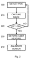
- Fig. 2 depicts flowchart implementing method steps according to one embodiment of the present invention. It should be mentioned here that these method steps are suitable to be implemented in a computer program which is stored on a chip or an internal or external memory of the portable terminal accessory 100.
- the geographical position 120 of the electronic unit such as the electronic unit 100 in Fig. 1 is determined. As described earlier, this can be done either by having a positioning unit PU1 built in to the portable terminal accessory 100 itself or by using the positioning unit PU2 in the portable unit 110.
- an image capturing unit of the electronic device such as the image capturing unit ICU in Fig. 1 captures an image of the environment in its field of view.
- the image data is then transmitted to a processing unit in the portable terminal where image processing algorithms are applied.
- a known object is detected in the image data at step 220, such as a landmark, a known building or some other known object the direction which the image capturing unit is facing can be calculated by comparing the geographical coordinates of the electronic device with the geographical coordinates of the known object.
- Known objects can by way of example be identified by comparing the object extracted from the image data supplied by the image capturing unit with objects known from a geographical or satellite map available in an internal memory of the portable terminal. It is also contemplated to have the geographical or satellite map stored on server in a communication network which the portable terminal can access via a receiver/transmitter unit, such as the receiver/transmitter unit Rx2/Tx2 in Fig. 1 .
- the method returns to detect the geographical position of the electronic device again at step 200.
- the geographical coordinates of the user carrying the electronic device and the geographical coordinates of the object identified are used at step 230 to calculate the direction or heading the image capturing unit of the electronic device is facing.
- the one or more sensors in the electronic device are recalibrated with the direction determined at step 230 as a new reference direction.
- a magnetometer which is built-in into the electronic device which has been affected by some magnetic disturbance in the environment around it can be recalibrated using the new reference direction from which the magnetic north and south poles can be determined.
- an accelerometer and a gyroscope sensor such as the accelerometer ACC and gyroscope sensors GYR from Fig. 1 can be recalibrated with the help of the new reference direction from which integration of the movement of the user of the electronic device can start.
- FIG. 3 Another embodiment of the present invention is presented in Fig. 3 where the first and a second image capturing unit ICU1 and ICU2 have replaced the first and second gyroscopes GYR1 and GYR2.
- the advantage of this second embodiment for the system, the mobile terminal accessory 100 and the portable terminal 110 is that they can be made at a lower cost, since one component (the gyroscope) is dispensed with.
- Another difference in this embodiment is that in the field of view of the first image capturing unit ICU1 objects 340, 350 and 360 are present which cannot be identified as known objects (i.e. no landmarks and no sun are visible) as was the case in the embodiment in Fig. 1 . Furthermore, in this embodiment, is used as a motion detector. In this case, the first and second gyroscopes GYR1 and GYR2 are dispensed with. It should be mentioned that, while the following description takes exclusive reference to the field of view of the first image capturing unit ICU1 in the mobile terminal accessory 300, it is equally valid for the field for the field of view of the second image capturing unit ICU2 located in the mobile terminal 310.
- Objects 340, 350 and 360, while unknown, are still identifiable as such by the first image capturing unit ICU1. While in the embodiment in Fig. 3 these identifiable objects are simplified for clarity as geometrical shapes, such as a circle 340, a triangle 350 and a rectangle 360, they may or may not be of geometrical shape as long as they are identifiable as objects from one frame (image data captured by the image capturing unit during a certain time instant) to another. Hence, identifiable objects may also include colors, intensity spots and so on.
- the first image capturing unit ICU1 is adapted to capture image data in its field of view 330 and to transmit the image data via the first receiver/transmitter Rx1/Tx1 to the processing unit CPU of the mobile terminal 310 which receives the image data sent via the second receiver/transmitter Rx2/Tx2.
- the first image capturing unit ICU1 is adapted to capture image data in its field of view 330 at at least two different time instants.
- the processing unit is adapted to compare the two image data sets and detect differences.
- the identifiable objects in the two image data sets are the circle 340, the triangle 350 and the rectangle 360.
- Figs. 4A-4F it will be useful to define the plane in which a lens of the image capturing unit is located as identical with the paper plane of the drawing. Moreover, an axis around which the lens of the image capturing unit is centered is depicted by the crosshair in Fig. 4A .
- the first image capturing unit ICU1 only comprises one image capturing device, one can obtain through imaging and image calculations applied to images from that capturing device a motion sensor system with six degrees of freedom, i.e. translation motion in three directions and rotational motion around three axes.
- a first rotational movement scenario is depicted, where the identifiable objects 340, 350 and 360 are detected by the processing unit CPU to have changed their position to 341, 351 and 361 by comparison of the image data sets taken at least at two different time instants by the first image capturing unit ICU1.
- Rotation around the axis around which the lens of the image capturing unit ICU1 is centered is detected by the processing unit CPU when all identified objects 340, 350 and 360 move and rotate with respect to a center point.
- the rotation direction of the identifiable objects is indicated by arrows, such as the arrow 412. During rotational movement the angular displacement of all objects is equal.
- Fig. 4B a second rotational movement scenario is depicted, where the identifiable objects 340, 350 and 360 are detected by the processing unit CPU to have changed their position to 342, 352 and 362. 2.
- Rotation around a vertical axis is detected by the processing unit CPU by comparing two or more image data sets taken at different time instants when all identifiable objects 340, 350 and 360 move the same distance sideways.
- the angular displacement is calculated by the displacement indicated by the arrows, such as the arrow 420 and the properties of the lens of the image capturing unit ICU1.
- a third rotational movement scenario is depicted, where the identifiable objects 340, 350 and 360 are detected by the processing unit CPU to have changed their position to 343, 353 and 363.
- Rotation around a horizontal axis is detected by the processing unit CPU by comparing two or more image data sets taken at different time instants when all identifiable objects 340, 350 and 360 move the same distance laterally as indicated by the arrows in the figure, such as the arrow 414.
- Fig. 4D a first translational movement scenario is depicted, where the identifiable objects 340, 350 and 360 are detected by the processing unit CPU to have changed their position to 344, 354 and 364.
- Translation along the axis around which the lens of the image capturing unit ICU1 is centered is detected by the processing unit CPU by comparing two or more image data sets taken at different time instants when all identifiable objects 340, 350 and 360 dissociate or consolidate from the image center as depicted in Fig. 4D .
- the arrows, such as the arrow 416 depict the direction of movement of the identifiable objects 340, 350 and 360 away from the image center.
- a second translational movement scenario is depicted, where the identifiable objects 340, 350 and 360 are detected by the processing unit CPU to have changed their position to 345, 355 and 365.
- Translation sideways i.e. along a horizontal axis is detected by the processing unit CPU by comparing two or more image data sets taken at different time instants when all identifiable objects 340, 350 and 360 move sideways.
- the difference compared to rotation around a vertical axis as depicted in Fig. 4B is that during translation the identifiable objects 340, 350 and 360 will have different displacement, depending on their distance from the image capturing unit ICU1.
- FIG. 4F a third translational movement scenario is depicted, where the identifiable objects 340, 350 and 360 are detected by the processing unit CPU to have changed their position to 345, 355 and 365.
- Vertical translation i.e. translation along a vertical axis is detected by the processing unit CPU by comparing two or more image data sets taken at different time instants when all identifiable objects 340, 350 and 360 vertically. This case is very similar to the case of sideways translation depicted in Fig. 4E .
- One other embodiment contemplated is to have the image capturing unit capture images of the environment around the portable terminal accessory in order to recalibrate magnetometers, gyroscopes, accelerometers, environmental sensors which are located in the portable terminal only.
- the portable terminal would have to be equipped with an image capturing unit of its own.
- the user of the portable terminal accessory and the portable terminal would after the determination of the geographical coordinates of the portable terminal accessory and those of the object recognized in the image data supplied by the image capturing unit would be required to point a camera or other image capturing means of the portable terminal towards the image capturing unit of the portable terminal accessory to be able to register the new reference direction the image capturing means of the portable unit is facing.
Landscapes
- Engineering & Computer Science (AREA)
- Physics & Mathematics (AREA)
- General Physics & Mathematics (AREA)
- Radar, Positioning & Navigation (AREA)
- Remote Sensing (AREA)
- Theoretical Computer Science (AREA)
- Computer Vision & Pattern Recognition (AREA)
- Multimedia (AREA)
- Manufacturing & Machinery (AREA)
- Artificial Intelligence (AREA)
- Health & Medical Sciences (AREA)
- Computing Systems (AREA)
- Databases & Information Systems (AREA)
- Evolutionary Computation (AREA)
- General Health & Medical Sciences (AREA)
- Medical Informatics (AREA)
- Software Systems (AREA)
- Telephone Function (AREA)
- Navigation (AREA)
- Length Measuring Devices By Optical Means (AREA)
Priority Applications (1)
| Application Number | Priority Date | Filing Date | Title |
|---|---|---|---|
| US13/663,552 US10210371B2 (en) | 2011-11-30 | 2012-10-30 | Method for calibration of a sensor unit and accessory comprising the same |
Applications Claiming Priority (1)
| Application Number | Priority Date | Filing Date | Title |
|---|---|---|---|
| US201161565010P | 2011-11-30 | 2011-11-30 |
Publications (2)
| Publication Number | Publication Date |
|---|---|
| EP2600109A2 true EP2600109A2 (de) | 2013-06-05 |
| EP2600109A3 EP2600109A3 (de) | 2015-03-25 |
Family
ID=45497813
Family Applications (1)
| Application Number | Title | Priority Date | Filing Date |
|---|---|---|---|
| EP12150122.5A Ceased EP2600109A3 (de) | 2011-11-30 | 2012-01-04 | Verfahren zur Kalibrierung einer Sensoreinheit und diese umfassendes Zubehörteil |
Country Status (2)
| Country | Link |
|---|---|
| US (1) | US10210371B2 (de) |
| EP (1) | EP2600109A3 (de) |
Cited By (5)
| Publication number | Priority date | Publication date | Assignee | Title |
|---|---|---|---|---|
| WO2015017931A1 (en) * | 2013-08-07 | 2015-02-12 | Blackberry Limited | Determining the distance of an object to an electronic device |
| EP2930466A1 (de) * | 2014-04-09 | 2015-10-14 | Vectronix AG | Handhaltbares Beobachtungsgerät mit einem digitalen Magnetkompass |
| WO2018085689A1 (en) * | 2016-11-03 | 2018-05-11 | Laine Juha Pekka J | Camera-based heading-hold navigation |
| CN109791048A (zh) * | 2016-08-01 | 2019-05-21 | 无限增强现实以色列有限公司 | 使用场景捕获数据校准惯性测量单元(imu)的组件的方法和系统 |
| CN109883452A (zh) * | 2019-04-16 | 2019-06-14 | 百度在线网络技术(北京)有限公司 | 参数标定方法和装置、电子设备、计算机可读介质 |
Families Citing this family (11)
| Publication number | Priority date | Publication date | Assignee | Title |
|---|---|---|---|---|
| US8743052B1 (en) * | 2012-11-24 | 2014-06-03 | Eric Jeffrey Keller | Computing interface system |
| CN105264405B (zh) * | 2013-06-11 | 2019-06-04 | 飞利浦灯具控股公司 | 校准传感器的方法 |
| JP2015035169A (ja) * | 2013-08-09 | 2015-02-19 | ソニー株式会社 | 電子機器、サーバ、電子機器の制御方法、情報処理方法および記録媒体 |
| US20150358777A1 (en) * | 2014-06-04 | 2015-12-10 | Qualcomm Incorporated | Generating a location profile of an internet of things device based on augmented location information associated with one or more nearby internet of things devices |
| US20150362579A1 (en) * | 2014-06-12 | 2015-12-17 | Google Inc. | Methods and Systems for Calibrating Sensors Using Recognized Objects |
| US20170173391A1 (en) * | 2015-12-18 | 2017-06-22 | MAD Apparel, Inc. | Adaptive calibration for sensor-equipped athletic garments |
| US10357688B2 (en) | 2016-11-18 | 2019-07-23 | MAD Apparel, Inc. | Exercise biofeedback using sensor-equipped athletic garments |
| US11179601B2 (en) | 2016-11-18 | 2021-11-23 | MAD Apparel, Inc. | Training program customization using sensor-equipped athletic garments |
| JP6674560B2 (ja) * | 2016-12-28 | 2020-04-01 | 本田技研工業株式会社 | 外界認識システム |
| US11246531B2 (en) | 2018-05-10 | 2022-02-15 | MAD Apparel, Inc. | Fatigue measurement in a sensor equipped garment |
| CN113566847B (zh) * | 2021-07-22 | 2022-10-11 | 北京百度网讯科技有限公司 | 导航校准方法和装置、电子设备、计算机可读介质 |
Family Cites Families (14)
| Publication number | Priority date | Publication date | Assignee | Title |
|---|---|---|---|---|
| DE10359415A1 (de) * | 2003-12-16 | 2005-07-14 | Trimble Jena Gmbh | Verfahren zur Kalibrierung eines Vermessungsgeräts |
| JP3900365B2 (ja) * | 2005-03-03 | 2007-04-04 | 三菱電機株式会社 | 測位装置および測位方法 |
| EP2013572A4 (de) * | 2006-04-28 | 2012-08-08 | Nokia Corp | Kalibration |
| KR100761011B1 (ko) * | 2006-05-30 | 2007-09-21 | 학교법인 인하학원 | 카메라형 태양센서를 이용한 관성항법시스템의자세보정장치 및 방법 |
| JP2008261755A (ja) * | 2007-04-12 | 2008-10-30 | Canon Inc | 情報処理装置、情報処理方法 |
| DE102007033486B4 (de) * | 2007-07-18 | 2010-06-17 | Metaio Gmbh | Verfahren und System zur Vermischung eines virtuellen Datenmodells mit einem von einer Kamera oder einer Darstellungsvorrichtung generierten Abbild |
| DE112009000480T5 (de) * | 2008-03-03 | 2011-04-07 | VideoIQ, Inc., Bedford | Dynamische Objektklassifikation |
| US8854453B2 (en) * | 2009-06-23 | 2014-10-07 | Here Global B.V. | Determining geographic position information from a single image |
| US8301202B2 (en) * | 2009-08-27 | 2012-10-30 | Lg Electronics Inc. | Mobile terminal and controlling method thereof |
| US8855929B2 (en) * | 2010-01-18 | 2014-10-07 | Qualcomm Incorporated | Using object to align and calibrate inertial navigation system |
| US8694051B2 (en) * | 2010-05-07 | 2014-04-08 | Qualcomm Incorporated | Orientation sensor calibration |
| US8565528B2 (en) * | 2010-12-17 | 2013-10-22 | Qualcomm Incorporated | Magnetic deviation determination using mobile devices |
| US8952682B2 (en) * | 2011-02-11 | 2015-02-10 | Blackberry Limited | System and method for calibrating a magnetometer with visual affordance |
| US8594374B1 (en) * | 2011-03-30 | 2013-11-26 | Amazon Technologies, Inc. | Secure device unlock with gaze calibration |
-
2012
- 2012-01-04 EP EP12150122.5A patent/EP2600109A3/de not_active Ceased
- 2012-10-30 US US13/663,552 patent/US10210371B2/en active Active
Non-Patent Citations (1)
| Title |
|---|
| None |
Cited By (9)
| Publication number | Priority date | Publication date | Assignee | Title |
|---|---|---|---|---|
| WO2015017931A1 (en) * | 2013-08-07 | 2015-02-12 | Blackberry Limited | Determining the distance of an object to an electronic device |
| EP2930466A1 (de) * | 2014-04-09 | 2015-10-14 | Vectronix AG | Handhaltbares Beobachtungsgerät mit einem digitalen Magnetkompass |
| US9918044B2 (en) | 2014-04-09 | 2018-03-13 | Safran Vectronix Ag | Handheld observation device comprising a digital magnetic compass |
| CN109791048A (zh) * | 2016-08-01 | 2019-05-21 | 无限增强现实以色列有限公司 | 使用场景捕获数据校准惯性测量单元(imu)的组件的方法和系统 |
| EP3491334A4 (de) * | 2016-08-01 | 2020-04-08 | Alibaba Technology (Israel) Ltd. | Verfahren und system zur kalibrierung von komponenten einer inertialmesseinheit (imu) unter verwendung von szenenerfassten daten |
| US11125581B2 (en) | 2016-08-01 | 2021-09-21 | Alibaba Technologies (Israel) LTD. | Method and system for calibrating components of an inertial measurement unit (IMU) using scene-captured data |
| WO2018085689A1 (en) * | 2016-11-03 | 2018-05-11 | Laine Juha Pekka J | Camera-based heading-hold navigation |
| US10724871B2 (en) | 2016-11-03 | 2020-07-28 | The Charles Stark Draper Laboratory, Inc. | Camera-based heading-hold navigation |
| CN109883452A (zh) * | 2019-04-16 | 2019-06-14 | 百度在线网络技术(北京)有限公司 | 参数标定方法和装置、电子设备、计算机可读介质 |
Also Published As
| Publication number | Publication date |
|---|---|
| US10210371B2 (en) | 2019-02-19 |
| EP2600109A3 (de) | 2015-03-25 |
| US20130136301A1 (en) | 2013-05-30 |
Similar Documents
| Publication | Publication Date | Title |
|---|---|---|
| US10210371B2 (en) | Method for calibration of a sensor unit and accessory comprising the same | |
| US9683851B2 (en) | Indoor magnetic field based location discovery | |
| KR101728123B1 (ko) | 지구 자기장을 이용한 동시 로컬리제이션 및 매핑 | |
| US9599473B2 (en) | Utilizing magnetic field based navigation | |
| ES2776674T3 (es) | Calibración de sensor y estimación de posición en base a la determinación del punto de fuga | |
| US20150192656A1 (en) | Received signal direction determination in using multi-antennas receivers | |
| US20150092048A1 (en) | Off-Target Tracking Using Feature Aiding in the Context of Inertial Navigation | |
| US9706362B2 (en) | Information determination in a portable electronic device carried by a user | |
| US9797727B2 (en) | Method and apparatus for determination of misalignment between device and vessel using acceleration/deceleration | |
| Tiglao et al. | Smartphone-based indoor localization techniques: State-of-the-art and classification | |
| US10054442B2 (en) | Method and apparatus for handling vertical orientations of devices for constraint free portable navigation | |
| TWI612829B (zh) | 定位推播服務系統、使用者行動裝置及定位推播服務方法 | |
| Suprem et al. | Orientation and displacement detection for smartphone device based imus | |
| Kuusniemi et al. | Multi-sensor multi-network seamless positioning with visual aiding | |
| JP2016138864A (ja) | 測位装置、測位方法、コンピュータプログラム、及び記憶媒体 | |
| KR20160004084A (ko) | 실내 보행자 위치 추적 장치 및 방법 | |
| EP3014296A1 (de) | Systeme und verfahren zum nachweis von magnetischen und bewegungsbasierten markierungen | |
| KR102217556B1 (ko) | 상대위치측정장치 및 상대위치측정시스템 | |
| TWM530957U (zh) | 室內定位裝置 |
Legal Events
| Date | Code | Title | Description |
|---|---|---|---|
| PUAI | Public reference made under article 153(3) epc to a published international application that has entered the european phase |
Free format text: ORIGINAL CODE: 0009012 |
|
| AK | Designated contracting states |
Kind code of ref document: A2 Designated state(s): AL AT BE BG CH CY CZ DE DK EE ES FI FR GB GR HR HU IE IS IT LI LT LU LV MC MK MT NL NO PL PT RO RS SE SI SK SM TR |
|
| AX | Request for extension of the european patent |
Extension state: BA ME |
|
| PUAL | Search report despatched |
Free format text: ORIGINAL CODE: 0009013 |
|
| AK | Designated contracting states |
Kind code of ref document: A3 Designated state(s): AL AT BE BG CH CY CZ DE DK EE ES FI FR GB GR HR HU IE IS IT LI LT LU LV MC MK MT NL NO PL PT RO RS SE SI SK SM TR |
|
| AX | Request for extension of the european patent |
Extension state: BA ME |
|
| RIC1 | Information provided on ipc code assigned before grant |
Ipc: G01C 17/38 20060101ALI20150219BHEP Ipc: G01C 25/00 20060101AFI20150219BHEP |
|
| 17P | Request for examination filed |
Effective date: 20150925 |
|
| RBV | Designated contracting states (corrected) |
Designated state(s): AL AT BE BG CH CY CZ DE DK EE ES FI FR GB GR HR HU IE IS IT LI LT LU LV MC MK MT NL NO PL PT RO RS SE SI SK SM TR |
|
| RAP1 | Party data changed (applicant data changed or rights of an application transferred) |
Owner name: SONY MOBILE COMMUNICATIONS AB |
|
| 17Q | First examination report despatched |
Effective date: 20170608 |
|
| STAA | Information on the status of an ep patent application or granted ep patent |
Free format text: STATUS: THE APPLICATION HAS BEEN REFUSED |
|
| 18R | Application refused |
Effective date: 20190512 |