EP2599701A2 - Scooter-type motorcycle - Google Patents
Scooter-type motorcycle Download PDFInfo
- Publication number
- EP2599701A2 EP2599701A2 EP12194389.8A EP12194389A EP2599701A2 EP 2599701 A2 EP2599701 A2 EP 2599701A2 EP 12194389 A EP12194389 A EP 12194389A EP 2599701 A2 EP2599701 A2 EP 2599701A2
- Authority
- EP
- European Patent Office
- Prior art keywords
- canister
- vehicle
- intake system
- hose
- vehicle body
- Prior art date
- Legal status (The legal status is an assumption and is not a legal conclusion. Google has not performed a legal analysis and makes no representation as to the accuracy of the status listed.)
- Granted
Links
Images




Classifications
-
- B—PERFORMING OPERATIONS; TRANSPORTING
- B62—LAND VEHICLES FOR TRAVELLING OTHERWISE THAN ON RAILS
- B62J—CYCLE SADDLES OR SEATS; AUXILIARY DEVICES OR ACCESSORIES SPECIALLY ADAPTED TO CYCLES AND NOT OTHERWISE PROVIDED FOR, e.g. ARTICLE CARRIERS OR CYCLE PROTECTORS
- B62J37/00—Arrangements of fuel supply lines, taps, or the like, on motor cycles or engine-assisted cycles
-
- B—PERFORMING OPERATIONS; TRANSPORTING
- B62—LAND VEHICLES FOR TRAVELLING OTHERWISE THAN ON RAILS
- B62K—CYCLES; CYCLE FRAMES; CYCLE STEERING DEVICES; RIDER-OPERATED TERMINAL CONTROLS SPECIALLY ADAPTED FOR CYCLES; CYCLE AXLE SUSPENSIONS; CYCLE SIDECARS, FORECARS, OR THE LIKE
- B62K2202/00—Motorised scooters
Definitions
- the present invention relates to a motorcycle, particularly, scooter-type motorcycle, provided with a discharge suppression device for fuel evaporation gas (hereinafter referred to as fuel evaporation gas discharge suppression device) provided with a canister.
- a discharge suppression device for fuel evaporation gas hereinafter referred to as fuel evaporation gas discharge suppression device
- scooter-type motorcycle including a fuel evaporation gas discharge suppression device having a canister that temporarily adsorbs a fuel evaporation gas generated in a fuel tank and purges (emits) the fuel evaporation gas to an intake system.
- Patent Document 1 Japanese Patent Laid-Open Publication No. 10-324281
- the canister receives heat from the muffler after operation stop of an engine and activated carbon in the canister is heated to a high temperature. In such a case, adsorption performance of a fuel evaporation gas by the canister is deteriorated.
- Patent Document 2 Japanese Patent Application No. 2005-69232 discloses a structure in which a canister is placed in a vehicle body cover in a front portion of a vehicle body so as to space the canister from a muffler.
- a fuel evaporation gas discharge suppression device having a canister purges (emits) adsorbed fuel from the canister to an intake system and burns the fuel in an engine, and because of such reason, in a structure in which the canister is excessively separated from a muffler, lengths of various hoses such as a purge hose coupling the canister and the intake system are made longer, thus being disadvantageous.
- a scooter-type motorcycle such as a small scooter including an engine unit swingable in a vertical direction of a vehicle with respect to a vehicle body frame
- an intake system swings together with the engine unit.
- various hoses such as a purge hose having an increased length may significantly vibrate in the vertical direction and interfere with peripheral components, thereby, for example, damaging the purge hose to emit a fuel evaporation gas to an outside of the vehicle.
- the present invention is achieved in view of the above described circumstances and an object thereof is to provide a scooter-type motorcycle capable of increasing adsorption performance of a fuel evaporation gas by a canister and preventing damage to various hoses connected to the canister.
- a scooter-type motorcycle which includes:
- the canister is mounted to the vehicle body frame in a vicinity of and immediately above a center of a swinging motion of the engine unit on a side view of the vehicle with an upper end of the canister being located below a lower end of the intake system.
- the canister is mounted with a longitudinal direction thereof being directed in the vertical direction of the vehicle, the fuel tank and the canister are connected to each other through a surge hose, and the intake system and the canister are connected to each other through a purge hose, the surge hose and the purge hose being connected to an upper portion of the canister, and a canister air hose having one end opened to atmosphere is connected, at the other end, to a lower portion of the canister.
- the canister is mounted to the vehicle body frame with an upper portion thereof being tilted forward of the vehicle.
- the canister may include a purge valve at a top portion thereof, the purge valve includes a canister vacuum hose connecting a diaphragm chamber thereof and the intake system, and the canister vacuum hose is provided adjacent to and substantially in parallel with the purge hose.
- the canister vacuum hose is located at the front of a virtual line connecting an intake system side connection end and a canister side connection end in the vehicle, and essential portions thereof are provided in parallel with the virtual line on side view of the vehicle in an empty state of the vehicle.
- the purge hose and the canister vacuum hose may be provided to intersect a virtual line connecting the intake system side connection end of the canister vacuum hose in the empty state of the vehicle and the center of the swinging motion of the engine unit on side view of the vehicle.
- the engine unit is set with an angle ⁇ formed between a position of the canister vacuum hose in the empty state of the vehicle and a position of the canister vacuum hose in the maximum extension state of the vehicle being smaller than an angle ⁇ formed between the position of the canister vacuum hose in the empty state of the vehicle and a position of the canister vacuum hose in a maximum pressure state of the vehicle on side view of the vehicle.
- the canister can be spaced from the exhaust system, thereby preventing activated carbon in the canister from being heated to a high temperature to reduce adsorption performance of the fuel evaporation gas (HC, CO).
- the cylinder assembly is located between the exhaust system and the canister, thereby preventing transfer of high temperature atmosphere around the exhaust system and also radiation heat from the exhaust system to the canister.
- the canister is located on one side that is the side of the intake system in the cylinder assembly, the length of a hose connecting the canister and the intake system can be reduced, thus avoiding the interference between the hose and the peripheral components even when the engine unit and the intake system swing in the vertical direction of the vehicle. This arrangement can prevent damage to the hose.
- Fig. 1 is a left side perspective view showing an embodiment of a scooter-type motorcycle according to the present invention
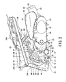
- Fig. 2 is a left side view showing a rear half portion of the scooter-type motorcycle in Fig. 1 with a frame cover being removed.
- terms of front, rear, left, right, upper, lower representing direction are used in the illustrated state or with reference to a rider on a vehicle.
- a scooter-type motorcycle 10 includes an underbone vehicle body frame 11.
- one main frame 13 extends downward from a rear portion of a steering pipe 12 at a front head portion, and a pair of left and right first rear frames 14A extends rearward and obliquely upward from a lower portion of the main frame 13, and a second rear frame 14B having a U-shape in a plan view is integrated with the first rear frame 14A.
- a pair of front forks 15 is supported by the steering pipe 12 laterally pivotably with a handlebar 16, and a front wheel 17 is journaled on front ends of the front forks 15.
- an engine suspension bracket 18 is mounted to a connection portion between a rear end of the main frame 13 and the first rear frame 14A.
- An engine unit 20 is pivotably supported by the engine suspension bracket 18 around a pivot axis 21 swingably in a vertical direction via a link member 19.
- the pivot axis 21 is the center of the swinging motion of the engine unit 20, and reference numeral 22 in Fig. 2 denotes the center of a swinging motion of the link member 19 on a vehicle body side with respect to the engine suspension bracket 18.
- the engine unit 20 of the present embodiment is generally used for a scooter, and integrally includes an engine 23 and a transmission 24, and a rear wheel 25 is directly journaled on a rear portion of the transmission 24.
- a rear cushion unit 26 is vertically stretched between a rear portion of the transmission 24 and the second rear frame 14B, and the rear cushion unit 26 performs cushioning function and suspends the engine unit 20 and the rear wheel 25.
- the transmission 24 includes a belt-type continuously variable transmission and a final deceleration mechanism, both not shown, that change speed of and transmit rotation of the engine 23.
- a seat 27 is provided so as to be opened and/or closed.
- an article housing (storage) box 28 that can house or store an article such as a helmet is disposed above a cylinder assembly 32 (described later) in the vehicle body.
- a fuel tank 29 is disposed above an air cleaner 46 (described later) in the vehicle body.
- the article housing box 28 and the fuel tank 29 are mounted to and supported by the second rear frame 14B of the vehicle body frame 11.
- an upper opening 28A of the article housing box 28 is also opened for putting an article such as helmet into the article housing box 28 or taking out thereof from the article housing box 28.
- Front portions of the vehicle body frame 11 and the engine unit 20 are entirely covered with a frame cover 30 made of synthetic resin to improve an outer appearance of the vehicle body and protect internal components or parts of the vehicle.
- the engine 23 is configured so that the cylinder assembly 32 extends forward from a crankcase 31 to be tilted forward substantially in a horizontal direction.
- a casing (i.e., transmission casing 33) of the transmission 24 integrally extends rearward of the vehicle body from one end side of the crankcase 31 in a vehicle width direction (left side in this embodiment).
- the crankcase 31 has a structure laterally split into two sections, and a left-side crankcase portion extends rearward of the vehicle body to constitute the transmission casing 33 together with a transmission cover.
- the cylinder assembly 32 is configured so that a cylinder 34, a cylinder head 35, and a head cover 36 are arranged in an overlapped manner in this order from the upper side of the crankcase 31.
- the cylinder 34 and the cylinder head 35 are covered with a cylinder cowling 37 made of synthetic resin.
- cooling air is introduced from an air introduction port 38 in Fig. 4 when a cooling fan, not shown, mounted to a crankshaft, not shown, of the engine 23 is driven (rotated) to forcedly cool the cylinder 34 and the cylinder head 35.
- the air introduction port 38 is opened in a right side surface of the cylinder cowling 37.
- the cooling air having cooled the cylinder 34 and the cylinder head 35 is discharged from an air discharge port 39 formed in a lower surface of the cylinder cowling 37.
- Reference numeral 40 in Fig. 4 denotes an air duct for cooling a belt through which the air is introduced into a belt chamber in the transmission casing 33.
- an intake system 41 is connected to an upper portion of the cylinder head 35 of the cylinder assembly 32, and an exhaust system 42 is connected to a lower portion thereof.
- the intake system 41 and the exhaust system 42 are located on the opposite sides in the vehicle width direction with the cylinder assembly 32 therebetween and extend rearward of the vehicle.
- the intake system 41 is disposed above the transmission casing 33 on the same side (left side in the present embodiment) as the transmission casing 33 in the vehicle width direction.
- the intake system 41 includes an intake pipe 43 connected to an intake port, not shown, formed in the cylinder head 35 and extending rearward of the vehicle in a curved shape, a carburetor 44 connected to the intake pipe 43, a connecting tube 45 connected to the carburetor 44, and an air cleaner 46 connected to the connecting tube 45.
- An inlet pipe 47 is provided in the air cleaner 46.
- Clean air from which dust is removed by the air cleaner 46 is supplied to the carburetor 44 as an intake air.
- the carburetor 44 introduces and atomizes a predetermined amount of fuel from the fuel tank 29 through a fuel hose 48 according to an intake amount for the intake port, and supplies the fuel to the intake port of the engine 23 (cylinder head 35) together with the intake air.
- reference numeral 49 in Figs. 2 , 3 and 6 denotes a fuel drain hose
- reference numeral 29A denotes a fuel tank cover covering an upper portion of the fuel tank 29
- Reference numeral 50 in Figs. 5 to 7 denotes a breather hose that introduces a blow-by gas in the engine 23 to the air cleaner 46.
- the intake port is opened in a left side surface at a left upper corner of the cylinder head 35.
- the intake pipe 43 connected to the intake port has a curved shape extending outward in the vehicle width direction and then extending rearward.
- the intake system 41 is arranged in a position biased leftward of the vehicle with respect to a cylinder axis O of the cylinder assembly 32, thereby avoiding interference with a bottom surface of the article housing box 28 ( Figs. 1 and 2 ) provided above the intake system 41.
- the article housing box 28 can be provided in a low position to lower a seat surface of the seat 27 disposed above the article housing box 28, thereby providing a satisfactory foot resting comfort of a rider during the stop time of the vehicle.
- the exhaust system 42 includes an exhaust pipe 51 connected to an exhaust port, not shown, formed in the cylinder head 35, and a muffler 52 connected to a downstream end of the exhaust pipe 51.
- the exhaust pipe 51 extends downward of the vehicle body from a lower surface of the cylinder head 35, curves toward one side in the vehicle width direction, and then extends rearward of the vehicle through one side of the engine 23.
- the exhaust pipe 51 and the muffler 52 are arranged on the right side in the vehicle width direction.
- the muffler 52 is covered with a muffler cover 53, and secured via a muffler bracket 54 to a rear portion of a right side surface of the crankcase 31 of the engine 23 on the right side in the vehicle width direction.
- the exhaust system 42 is configured to be swingable, together with the intake system 41, around the pivot axis 21 vertically of the vehicle in synchronization with the engine unit 20.
- a fuel evaporation gas discharge suppression device that suppresses the discharge of a fuel evaporation gas generated in the fuel tank 29, for example, during the engine operation stop time, to the outside of the vehicle.
- the fuel evaporation gas discharge suppression device 55 includes a canister 56 that temporality adsorbs the fuel evaporation gas generated in the fuel tank 29 and purges (emits) the gas into the intake system 41.
- the canister 56 is disposed in a space 57 formed on one side portion, that is a side of the intake system 41 (left side of the vehicle), of the cylinder assembly 32 and at a front of the transmission casing 33 in the vehicle body.
- the canister 56 is located on the side opposite to the exhaust system 42 with the cylinder assembly 32 therebetween, and thus, heat from the exhaust pipe 51 and the muffler 52 of the exhaust system 42 is blocked by the cylinder assembly 32, thereby preventing the heat from transferring to the canister 56.
- the canister 56 is mounted to the engine suspension bracket 18 of the vehicle body frame 11 using the canister bracket 58, proximal to and immediately above the pivot axis 21 that is the center of a swinging motion of the engine unit 20 on the side view of the vehicle. Further, the canister 56 is located so that an upper end thereof is positioned below a lower end of the intake system 41 (particularly, the carburetor 44).
- the portion above the canister 56 in the intake system 41, in which components such as the intake pipe 43 and the carburetor 44 are disposed, is positioned above the pivot axis 21, and hence, that portion moves along a substantially horizontal swinging path when the engine unit 20 swings. Therefore, as described above, since the canister 56 is located in the vicinity of and immediately above the pivot axis 21 and below the intake system 41, the canister 56 can be prevented from coming into contact with the intake system 41 even when the engine unit 20 swings.
- the canister 56 is arranged under the intake system 41 in the space 57, thereby allowing effective use of a dead space.
- the canister 56 is located with the longitudinal direction thereof being directed in the vertical direction of the vehicle, and mounted to the engine suspension bracket 18 of the vehicle body frame 11 with an upper portion of the canister 56 being tilted forward of the vehicle. According to such arrangement, the interference between the canister 56 and peripheral components can be prevented even if the engine unit 20 swings in the vertical direction of the vehicle during the driving of the vehicle. More specifically, the transmission casing 33 is disposed on the rear side of the canister 56, and if the front end portion of the transmission casing 33 moves close to the canister 56 by the swinging motion of the engine unit 20, the canister 56 and the transmission casing 33 do not interfere with each other because the canister 56 is tilted forward.
- a surge hose 60 from the fuel tank 29 is connected to a rear surface of an upper portion of the canister 56, and the fuel evaporation gas generated in the fuel tank 29 is introduced into the canister 56 and adsorbed by the activated carbon 59 in the canister 56.
- a purge hose 61 communicating with the carburetor 44 of the intake system 41 is connected to a front surface of the upper portion of the canister 56, and a purge valve 63 described later serves to switch the communication and blocking between the inside of the canister 56 and the intake system 41 (carburetor 44).
- a canister air hose 62 having one end opened to atmosphere is connected to a lower portion of the canister 56, and the inside of the canister 56 always communicates with outside air.
- the canister 56 includes the purge valve 63 at a top.
- the purge valve 63 includes a canister vacuum hose 64 connecting a diaphragm upper chamber 66A thereof and the intake system 41 (intake pipe 43).
- the purge valve 63 is configured so that a diaphragm 65 is provided to divide between a diaphragm upper chamber 66A and a diaphragm lower chamber 66B, a spring 67 that urges the diaphragm 65 is placed in the diaphragm upper chamber 66A, and a valve body 68 is secured to the diaphragm 65.
- the diaphragm lower chamber 66B communicates with a housing chamber 70 housing the activated carbon 59 through a communication hole 69.
- the valve body 68 is pressed against a valve seat 71 by action of a biasing force of the spring 67 to block the communication between the diaphragm lower chamber 66B and the purge hose 61 (i.e., to close the purge valve 63).
- the diaphragm upper chamber 66A communicates with the canister vacuum hose 64.
- the purge valve 63 is always closed by the biasing force of the spring 67.
- the diaphragm 65 is moved against the biasing force of the spring 67, and thus, the valve body 68 is separated from the valve seat 71 to thereby open the purge valve 63.
- the fuel evaporation gas adsorbed by the activated carbon 59 in the canister 56 is purged (emitted), flows in the purge hose 61 through the communication hole 69 and the diaphragm lower chamber 66B, and is supplied to the intake system 41 (carburetor 44).
- the fuel evaporation gas adsorbed in the canister 56 during stop of the engine 23 is purged into the carburetor 44 of the intake system 41 during the operation of the engine 23, sucked into a combustion chamber of the engine 23 together with premixed air and burned. This operation suppresses emission of the fuel evaporation gas generated in the fuel tank 29 to the outside of the vehicle.
- the purge hose 61 is connected to the carburetor 44 of the intake system 41 and communicated with an intake passage (not shown) of the carburetor 44 on a downstream side of a throttle valve, now shown, disposed in the intake passage.
- the canister vacuum hose 64 is disposed adjacent to and substantially in parallel with the purge hose 61, connected to a three-way joint 72 mounted to the intake pipe 43, and introduces negative pressure generated in the intake passage on the downstream side of the carburetor 44 into the diaphragm upper chamber 66A in the purge valve 63 of the canister 56.
- a secondary air vacuum hose 75 as another negative pressure hose for introducing intake negative pressure into a diaphragm chamber, not shown, in the air cut valve 74 of a secondary air supply device 73 is connected to one remaining end of the three-way joint 72.
- the secondary air supply device 73 is configured so that when exhaust pulsation brings negative pressure in an exhaust port of the cylinder head 35 of the engine 23, a lead valve, not shown, is opened to thereby introduce fresh air (secondary air) from a secondary air hose 76 (see Figs. 7 and 8 ) into the exhaust port.
- fresh air secondary air
- a secondary air hose 76 see Figs. 7 and 8
- oxygen is supplied into exhaust air to cause oxidation reaction of HC or CO in the exhaust air, or promote the action of a catalyst to reduce harmful emissions.
- the throttle valve is fully closed in a high revolution state of the engine 23 as in rapid deceleration, the intake negative pressure is increased to cause a rich air/fuel ratio.
- after-fire may occur to damage the catalyst or the like.
- the air cut valve 74 is provided to block the secondary air from the secondary air hose 76 when the intake negative pressure higher than predetermined intake negative pressure is generated.
- the air cut valve 74 is always opened, and when an excessive negative pressure is generated, the excessive negative pressure acts through the secondary air vacuum hose 75 on the diaphragm chamber in the air cut valve 74, and the diaphragm is thereby moved to close the air cut valve 74. According to this operation, the supply of the secondary air from the secondary air hose 76 to the exhaust port can be blocked.
- the canister vacuum hose 64 is disposed in front of a virtual line M connecting an intake system side connection end (that is, an end on a side of the three-way joint) X and a canister side connection end (that is, an end on a side of the purge valve) Y in the vehicle.
- the canister vacuum hose 64 can be arranged in a shortest path, and the canister vacuum hose 64 can be housed in a narrow space above the canister 56, thereby preventing the canister vacuum hose 64 from significantly vibrating together with the purge hose 61 and interfering with, particularly, the first rear frame 14A of the vehicle body frame 11 when the engine unit 20 swings.
- reference character L0 denotes a position of the canister vacuum hose 64 in the empty state of the vehicle
- reference character L1 denotes a position of the canister vacuum hose 64 in the maximum pressure state of the rear cushion unit 26 (maximum pressure state of the vehicle)
- reference character L2 denotes a position of the canister vacuum hose 64 in the maximum extension state of the rear cushion unit 26 (maximum extension state of the vehicle).
- the canister vacuum hose 64 and the purge hose 61 disposed adjacent to and substantially in parallel with each other are provided to intersect a virtual line N connecting the intake system side connection end X of the canister vacuum hose 64 in the empty state of the vehicle and the pivot axis 21 that is the center of a swinging motion of the engine unit 20.
- component of force F1 orthogonal to the longitudinal direction of the hoses (the canister vacuum hose 64 and the purge hose 61) constitutes a force to move the hoses.
- the component of force F1 is smaller than the inertial force F, amplitude of vibration of the hoses is suppressed as compared to the case where the hoses (the canister vacuum hose 64 and the purge hose 61) are provided substantially in parallel with the virtual line N.
- the engine unit 20 is provided so that an angle ⁇ formed between the position L0 of the canister vacuum hose 64 in the empty state of the vehicle and the position L2 of the canister vacuum hose 64 in the maximum extension state of the vehicle is smaller than an angle ⁇ formed between the position L0 of the canister vacuum hose 64 in the empty state of the vehicle and the position L1 of the canister vacuum hose 64 in the maximum pressure state of the vehicle on side view of the vehicle.
- the canister vacuum hose 64 is prevented from being crushed near the canister side connection end Y and blocking an inner passage when the engine unit 20 swings to be the maximum extension state of the vehicle.
- the purge hose 61 is provided in parallel with the canister vacuum hose 64, the deformation near the canister side connection end of the purge hose 61 is the same as that of the canister vacuum hose 64, thereby preventing the inner passage of the purge hose 61 from being blocked.
Landscapes
- Engineering & Computer Science (AREA)
- Mechanical Engineering (AREA)
- Supplying Secondary Fuel Or The Like To Fuel, Air Or Fuel-Air Mixtures (AREA)
- Automatic Cycles, And Cycles In General (AREA)
- Exhaust Silencers (AREA)
Abstract
Description
- The present invention relates to a motorcycle, particularly, scooter-type motorcycle, provided with a discharge suppression device for fuel evaporation gas (hereinafter referred to as fuel evaporation gas discharge suppression device) provided with a canister.
- There is known a scooter-type motorcycle including a fuel evaporation gas discharge suppression device having a canister that temporarily adsorbs a fuel evaporation gas generated in a fuel tank and purges (emits) the fuel evaporation gas to an intake system.
- As described in Patent Document 1 (Japanese Patent Laid-Open Publication No.
10-324281 - In view of such fact, for example, Patent Document 2 (Japanese Patent Application No.
2005-69232 - However, generally, a fuel evaporation gas discharge suppression device having a canister purges (emits) adsorbed fuel from the canister to an intake system and burns the fuel in an engine, and because of such reason, in a structure in which the canister is excessively separated from a muffler, lengths of various hoses such as a purge hose coupling the canister and the intake system are made longer, thus being disadvantageous.
- In a scooter-type motorcycle such as a small scooter including an engine unit swingable in a vertical direction of a vehicle with respect to a vehicle body frame, an intake system swings together with the engine unit. Thus, various hoses such as a purge hose having an increased length may significantly vibrate in the vertical direction and interfere with peripheral components, thereby, for example, damaging the purge hose to emit a fuel evaporation gas to an outside of the vehicle.
- The present invention is achieved in view of the above described circumstances and an object thereof is to provide a scooter-type motorcycle capable of increasing adsorption performance of a fuel evaporation gas by a canister and preventing damage to various hoses connected to the canister.
- The above and other objects can be achieved according to the present invention by providing a scooter-type motorcycle which includes:
- a vehicle body to which a vehicle body frame is mounted;
- an engine unit supported to be swingable in a vertical direction of a vehicle with respect to the vehicle body frame, the engine unit integrally including an engine and a transmission, the engine being provided with a crankcase and a cylinder assembly extending forward of the vehicle from the crankcase;
- a fuel tank mounted to the vehicle body frame above the engine unit in the vehicle body;
- a fuel evaporation gas discharge suppression device that suppresses discharge of a fuel evaporation gas generated in the fuel tank; and
- an intake system and an exhaust system connected to a cylinder head of the cylinder assembly, the intake system and the exhaust system extending rearward of the vehicle on an opposite side in a vehicle width direction with the cylinder assembly being provided therebetween, wherein
- the transmission has a casing extending rearward of the vehicle body from the same side as the intake system on one end side of the crankcase in the vehicle width direction,
- the fuel evaporation gas discharge suppression device includes a canister that temporarily adsorbs the fuel evaporation gas and emits the gas to the intake system, and
- the canister is disposed in a space formed on one side that is a side of the intake system in the cylinder assembly and at a front of the transmission casing in the vehicle.
- In a preferred embodiment, the following modes may be adopted.
- It may be desired that the canister is mounted to the vehicle body frame in a vicinity of and immediately above a center of a swinging motion of the engine unit on a side view of the vehicle with an upper end of the canister being located below a lower end of the intake system.
- It may be desired that the canister is mounted with a longitudinal direction thereof being directed in the vertical direction of the vehicle, the fuel tank and the canister are connected to each other through a surge hose, and the intake system and the canister are connected to each other through a purge hose, the surge hose and the purge hose being connected to an upper portion of the canister, and a canister air hose having one end opened to atmosphere is connected, at the other end, to a lower portion of the canister.
- It may be also desired that the canister is mounted to the vehicle body frame with an upper portion thereof being tilted forward of the vehicle.
- The canister may include a purge valve at a top portion thereof, the purge valve includes a canister vacuum hose connecting a diaphragm chamber thereof and the intake system, and the canister vacuum hose is provided adjacent to and substantially in parallel with the purge hose.
- It may be desired that the canister vacuum hose is located at the front of a virtual line connecting an intake system side connection end and a canister side connection end in the vehicle, and essential portions thereof are provided in parallel with the virtual line on side view of the vehicle in an empty state of the vehicle.
- The purge hose and the canister vacuum hose may be provided to intersect a virtual line connecting the intake system side connection end of the canister vacuum hose in the empty state of the vehicle and the center of the swinging motion of the engine unit on side view of the vehicle.
- Furthermore, it may be also desired that the engine unit is set with an angle β formed between a position of the canister vacuum hose in the empty state of the vehicle and a position of the canister vacuum hose in the maximum extension state of the vehicle being smaller than an angle α formed between the position of the canister vacuum hose in the empty state of the vehicle and a position of the canister vacuum hose in a maximum pressure state of the vehicle on side view of the vehicle.
- According to the present invention of the characters mentioned above, the canister can be spaced from the exhaust system, thereby preventing activated carbon in the canister from being heated to a high temperature to reduce adsorption performance of the fuel evaporation gas (HC, CO). In particular, the cylinder assembly is located between the exhaust system and the canister, thereby preventing transfer of high temperature atmosphere around the exhaust system and also radiation heat from the exhaust system to the canister.
- Furthermore, since the canister is located on one side that is the side of the intake system in the cylinder assembly, the length of a hose connecting the canister and the intake system can be reduced, thus avoiding the interference between the hose and the peripheral components even when the engine unit and the intake system swing in the vertical direction of the vehicle. This arrangement can prevent damage to the hose.
- The nature and further characteristic features of the present invention will be made clearer from the following descriptions made with reference to the accompanying drawings.
-
-
Fig. 1 is a perspective (transparent) view showing an embodiment of a scooter-type motorcycle, as viewed from left side thereof, according to the present invention; -
Fig. 2 is a left side view showing a rear half portion of the scooter-type motorcycle inFig. 1 with a frame cover being removed; -
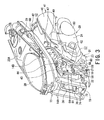
Fig. 3 is a perspective view showing the rear half portion inFig. 2 seen from a diagonally front side of a vehicle body; -
Fig. 4 is a front view showing the rear half portion inFig. 2 seen from a front side of the vehicle body; -
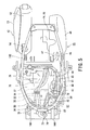
Fig. 5 is a plan view showing the rear half portion inFig. 2 seen from an upper side of the vehicle body; -
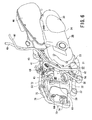
Fig. 6 is a perspective view showing an engine unit, an intake system, a fuel evaporation gas discharge suppression device, and so on of the vehicle body shown inFig. 2 ; -
Fig. 7 is a plan view ofFig. 6 ; -
Fig. 8 is a front view ofFig. 6 ; -
Fig. 9 is a partially enlarged side view showing surroundings of the fuel evaporation gas discharge suppression device inFig. 6 ; and -
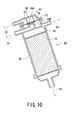
Fig. 10 is a side sectional view showing a canister inFig. 6 . - Hereunder, an embodiment for carrying out the present invention will be described with reference to the accompanying drawings.
-
Fig. 1 is a left side perspective view showing an embodiment of a scooter-type motorcycle according to the present invention, andFig. 2 is a left side view showing a rear half portion of the scooter-type motorcycle inFig. 1 with a frame cover being removed. In the following description of the embodiment, terms of front, rear, left, right, upper, lower representing direction are used in the illustrated state or with reference to a rider on a vehicle. - A scooter-
type motorcycle 10 includes an underbonevehicle body frame 11. In thevehicle body frame 11, onemain frame 13 extends downward from a rear portion of asteering pipe 12 at a front head portion, and a pair of left and right firstrear frames 14A extends rearward and obliquely upward from a lower portion of themain frame 13, and a secondrear frame 14B having a U-shape in a plan view is integrated with the firstrear frame 14A. - A pair of
front forks 15 is supported by thesteering pipe 12 laterally pivotably with ahandlebar 16, and afront wheel 17 is journaled on front ends of thefront forks 15. Meanwhile, as shown inFigs. 1 to 3 , anengine suspension bracket 18 is mounted to a connection portion between a rear end of themain frame 13 and the firstrear frame 14A. Anengine unit 20 is pivotably supported by theengine suspension bracket 18 around apivot axis 21 swingably in a vertical direction via alink member 19. Thepivot axis 21 is the center of the swinging motion of theengine unit 20, andreference numeral 22 inFig. 2 denotes the center of a swinging motion of thelink member 19 on a vehicle body side with respect to theengine suspension bracket 18. - The
engine unit 20 of the present embodiment is generally used for a scooter, and integrally includes anengine 23 and atransmission 24, and arear wheel 25 is directly journaled on a rear portion of thetransmission 24. Arear cushion unit 26 is vertically stretched between a rear portion of thetransmission 24 and the secondrear frame 14B, and therear cushion unit 26 performs cushioning function and suspends theengine unit 20 and therear wheel 25. Herein, thetransmission 24 includes a belt-type continuously variable transmission and a final deceleration mechanism, both not shown, that change speed of and transmit rotation of theengine 23. - Above the second
rear frame 14B of thevehicle body frame 11, aseat 27 is provided so as to be opened and/or closed. Under theseat 27 in the vehicle, an article housing (storage)box 28 that can house or store an article such as a helmet is disposed above a cylinder assembly 32 (described later) in the vehicle body. - A
fuel tank 29 is disposed above an air cleaner 46 (described later) in the vehicle body. Thearticle housing box 28 and thefuel tank 29 are mounted to and supported by the secondrear frame 14B of thevehicle body frame 11. When theseat 27 is opened, anupper opening 28A of thearticle housing box 28 is also opened for putting an article such as helmet into thearticle housing box 28 or taking out thereof from thearticle housing box 28. - Front portions of the
vehicle body frame 11 and theengine unit 20 are entirely covered with aframe cover 30 made of synthetic resin to improve an outer appearance of the vehicle body and protect internal components or parts of the vehicle. - As shown in
Figs. 1 and7 , theengine 23 is configured so that thecylinder assembly 32 extends forward from acrankcase 31 to be tilted forward substantially in a horizontal direction. A casing (i.e., transmission casing 33) of thetransmission 24 integrally extends rearward of the vehicle body from one end side of thecrankcase 31 in a vehicle width direction (left side in this embodiment). Specifically, thecrankcase 31 has a structure laterally split into two sections, and a left-side crankcase portion extends rearward of the vehicle body to constitute thetransmission casing 33 together with a transmission cover. - As shown in
Fig. 1 , thecylinder assembly 32 is configured so that acylinder 34, acylinder head 35, and ahead cover 36 are arranged in an overlapped manner in this order from the upper side of thecrankcase 31. Thecylinder 34 and thecylinder head 35 are covered with acylinder cowling 37 made of synthetic resin. - In the
cylinder cowl 37, cooling air is introduced from anair introduction port 38 inFig. 4 when a cooling fan, not shown, mounted to a crankshaft, not shown, of theengine 23 is driven (rotated) to forcedly cool thecylinder 34 and thecylinder head 35. Theair introduction port 38 is opened in a right side surface of thecylinder cowling 37. The cooling air having cooled thecylinder 34 and thecylinder head 35 is discharged from anair discharge port 39 formed in a lower surface of thecylinder cowling 37. -
Reference numeral 40 inFig. 4 denotes an air duct for cooling a belt through which the air is introduced into a belt chamber in thetransmission casing 33. - As shown in
Figs. 4 to 8 (particularly,Figs. 4 and5 ), anintake system 41 is connected to an upper portion of thecylinder head 35 of thecylinder assembly 32, and anexhaust system 42 is connected to a lower portion thereof. Theintake system 41 and theexhaust system 42 are located on the opposite sides in the vehicle width direction with thecylinder assembly 32 therebetween and extend rearward of the vehicle. Theintake system 41 is disposed above thetransmission casing 33 on the same side (left side in the present embodiment) as thetransmission casing 33 in the vehicle width direction. - Particularly as shown in
Figs. 4 and7 , theintake system 41 includes anintake pipe 43 connected to an intake port, not shown, formed in thecylinder head 35 and extending rearward of the vehicle in a curved shape, acarburetor 44 connected to theintake pipe 43, a connectingtube 45 connected to thecarburetor 44, and anair cleaner 46 connected to the connectingtube 45. Aninlet pipe 47 is provided in theair cleaner 46. - Clean air from which dust is removed by the
air cleaner 46 is supplied to thecarburetor 44 as an intake air. Thecarburetor 44 introduces and atomizes a predetermined amount of fuel from thefuel tank 29 through afuel hose 48 according to an intake amount for the intake port, and supplies the fuel to the intake port of the engine 23 (cylinder head 35) together with the intake air. - Furthermore,
reference numeral 49 inFigs. 2 ,3 and6 denotes a fuel drain hose, and reference numeral 29A denotes a fuel tank cover covering an upper portion of thefuel tank 29.Reference numeral 50 inFigs. 5 to 7 denotes a breather hose that introduces a blow-by gas in theengine 23 to theair cleaner 46. - With reference to
Figs. 6 to 8 , theintake system 41 will be further described in detail. The intake port is opened in a left side surface at a left upper corner of thecylinder head 35. Theintake pipe 43 connected to the intake port has a curved shape extending outward in the vehicle width direction and then extending rearward. On a plan view of the vehicle inFigs. 5 and7 , theintake system 41 is arranged in a position biased leftward of the vehicle with respect to a cylinder axis O of thecylinder assembly 32, thereby avoiding interference with a bottom surface of the article housing box 28 (Figs. 1 and2 ) provided above theintake system 41. Thus, thearticle housing box 28 can be provided in a low position to lower a seat surface of theseat 27 disposed above thearticle housing box 28, thereby providing a satisfactory foot resting comfort of a rider during the stop time of the vehicle. - As shown in
Figs. 4 and5 , theexhaust system 42 includes anexhaust pipe 51 connected to an exhaust port, not shown, formed in thecylinder head 35, and amuffler 52 connected to a downstream end of theexhaust pipe 51. Theexhaust pipe 51 extends downward of the vehicle body from a lower surface of thecylinder head 35, curves toward one side in the vehicle width direction, and then extends rearward of the vehicle through one side of theengine 23. In the described embodiment, theexhaust pipe 51 and themuffler 52 are arranged on the right side in the vehicle width direction. Themuffler 52 is covered with amuffler cover 53, and secured via amuffler bracket 54 to a rear portion of a right side surface of thecrankcase 31 of theengine 23 on the right side in the vehicle width direction. As mentioned above and as shown inFigs. 1 and2 , theexhaust system 42 is configured to be swingable, together with theintake system 41, around thepivot axis 21 vertically of the vehicle in synchronization with theengine unit 20. - As shown in
Figs. 2 ,3 and6 , in the scooter-type motorcycle 10 of the present embodiment, a fuel evaporation gas discharge suppression device is provided that suppresses the discharge of a fuel evaporation gas generated in thefuel tank 29, for example, during the engine operation stop time, to the outside of the vehicle. The fuel evaporation gasdischarge suppression device 55 includes acanister 56 that temporality adsorbs the fuel evaporation gas generated in thefuel tank 29 and purges (emits) the gas into theintake system 41. - The
canister 56 is disposed in aspace 57 formed on one side portion, that is a side of the intake system 41 (left side of the vehicle), of thecylinder assembly 32 and at a front of thetransmission casing 33 in the vehicle body. Thus, thecanister 56 is located on the side opposite to theexhaust system 42 with thecylinder assembly 32 therebetween, and thus, heat from theexhaust pipe 51 and themuffler 52 of theexhaust system 42 is blocked by thecylinder assembly 32, thereby preventing the heat from transferring to thecanister 56. - The
canister 56 is mounted to theengine suspension bracket 18 of thevehicle body frame 11 using thecanister bracket 58, proximal to and immediately above thepivot axis 21 that is the center of a swinging motion of theengine unit 20 on the side view of the vehicle. Further, thecanister 56 is located so that an upper end thereof is positioned below a lower end of the intake system 41 (particularly, the carburetor 44). - The portion above the
canister 56 in theintake system 41, in which components such as theintake pipe 43 and thecarburetor 44 are disposed, is positioned above thepivot axis 21, and hence, that portion moves along a substantially horizontal swinging path when theengine unit 20 swings. Therefore, as described above, since thecanister 56 is located in the vicinity of and immediately above thepivot axis 21 and below theintake system 41, thecanister 56 can be prevented from coming into contact with theintake system 41 even when theengine unit 20 swings. Thecanister 56 is arranged under theintake system 41 in thespace 57, thereby allowing effective use of a dead space. - The
canister 56 is located with the longitudinal direction thereof being directed in the vertical direction of the vehicle, and mounted to theengine suspension bracket 18 of thevehicle body frame 11 with an upper portion of thecanister 56 being tilted forward of the vehicle. According to such arrangement, the interference between thecanister 56 and peripheral components can be prevented even if theengine unit 20 swings in the vertical direction of the vehicle during the driving of the vehicle. More specifically, thetransmission casing 33 is disposed on the rear side of thecanister 56, and if the front end portion of thetransmission casing 33 moves close to thecanister 56 by the swinging motion of theengine unit 20, thecanister 56 and thetransmission casing 33 do not interfere with each other because thecanister 56 is tilted forward. - As shown in
Figs. 2 ,6 and10 , asurge hose 60 from thefuel tank 29 is connected to a rear surface of an upper portion of thecanister 56, and the fuel evaporation gas generated in thefuel tank 29 is introduced into thecanister 56 and adsorbed by the activatedcarbon 59 in thecanister 56. - A
purge hose 61 communicating with thecarburetor 44 of theintake system 41 is connected to a front surface of the upper portion of thecanister 56, and apurge valve 63 described later serves to switch the communication and blocking between the inside of thecanister 56 and the intake system 41 (carburetor 44). Acanister air hose 62 having one end opened to atmosphere is connected to a lower portion of thecanister 56, and the inside of thecanister 56 always communicates with outside air. - The
canister 56 includes thepurge valve 63 at a top. Thepurge valve 63 includes acanister vacuum hose 64 connecting a diaphragmupper chamber 66A thereof and the intake system 41 (intake pipe 43). - As shown in
Fig. 10 , thepurge valve 63 is configured so that adiaphragm 65 is provided to divide between a diaphragmupper chamber 66A and a diaphragmlower chamber 66B, aspring 67 that urges thediaphragm 65 is placed in the diaphragmupper chamber 66A, and avalve body 68 is secured to thediaphragm 65. The diaphragmlower chamber 66B communicates with ahousing chamber 70 housing the activatedcarbon 59 through acommunication hole 69. Thevalve body 68 is pressed against avalve seat 71 by action of a biasing force of thespring 67 to block the communication between the diaphragmlower chamber 66B and the purge hose 61 (i.e., to close the purge valve 63). The diaphragmupper chamber 66A communicates with thecanister vacuum hose 64. - The
purge valve 63 is always closed by the biasing force of thespring 67. By means of an intake negative pressure acting from thecanister vacuum hose 64 on the diaphragmupper chamber 66A, thediaphragm 65 is moved against the biasing force of thespring 67, and thus, thevalve body 68 is separated from thevalve seat 71 to thereby open thepurge valve 63. In the opening state of thepurge valve 63, the fuel evaporation gas adsorbed by the activatedcarbon 59 in thecanister 56 is purged (emitted), flows in thepurge hose 61 through thecommunication hole 69 and the diaphragmlower chamber 66B, and is supplied to the intake system 41 (carburetor 44). - According to the manner described above, with reference to
Figs. 2 and6 , the fuel evaporation gas adsorbed in thecanister 56 during stop of theengine 23 is purged into thecarburetor 44 of theintake system 41 during the operation of theengine 23, sucked into a combustion chamber of theengine 23 together with premixed air and burned. This operation suppresses emission of the fuel evaporation gas generated in thefuel tank 29 to the outside of the vehicle. - As shown in
Fig. 7 , thepurge hose 61 is connected to thecarburetor 44 of theintake system 41 and communicated with an intake passage (not shown) of thecarburetor 44 on a downstream side of a throttle valve, now shown, disposed in the intake passage. - As shown in
Fig. 8 , thecanister vacuum hose 64 is disposed adjacent to and substantially in parallel with thepurge hose 61, connected to a three-way joint 72 mounted to theintake pipe 43, and introduces negative pressure generated in the intake passage on the downstream side of thecarburetor 44 into the diaphragmupper chamber 66A in thepurge valve 63 of thecanister 56. A secondaryair vacuum hose 75 as another negative pressure hose for introducing intake negative pressure into a diaphragm chamber, not shown, in the air cutvalve 74 of a secondaryair supply device 73 is connected to one remaining end of the three-way joint 72. - The secondary
air supply device 73 is configured so that when exhaust pulsation brings negative pressure in an exhaust port of thecylinder head 35 of theengine 23, a lead valve, not shown, is opened to thereby introduce fresh air (secondary air) from a secondary air hose 76 (seeFigs. 7 and8 ) into the exhaust port. Thus, oxygen is supplied into exhaust air to cause oxidation reaction of HC or CO in the exhaust air, or promote the action of a catalyst to reduce harmful emissions. However, for example, when the throttle valve is fully closed in a high revolution state of theengine 23 as in rapid deceleration, the intake negative pressure is increased to cause a rich air/fuel ratio. Thus, if secondary air is supplied into the exhaust air in this state, after-fire may occur to damage the catalyst or the like. - Then, the air cut
valve 74 is provided to block the secondary air from thesecondary air hose 76 when the intake negative pressure higher than predetermined intake negative pressure is generated. The air cutvalve 74 is always opened, and when an excessive negative pressure is generated, the excessive negative pressure acts through the secondaryair vacuum hose 75 on the diaphragm chamber in the air cutvalve 74, and the diaphragm is thereby moved to close the air cutvalve 74. According to this operation, the supply of the secondary air from thesecondary air hose 76 to the exhaust port can be blocked. - As shown in
Figs. 2 and9 , in the present embodiment, thecanister vacuum hose 64 is disposed in front of a virtual line M connecting an intake system side connection end (that is, an end on a side of the three-way joint) X and a canister side connection end (that is, an end on a side of the purge valve) Y in the vehicle. Furthermore, since the essential portions of thecanister vacuum hose 64 are provided substantially linearly in parallel with the virtual line M on side view of the vehicle in an empty state of the vehicle, thecanister vacuum hose 64 can be arranged in a shortest path, and thecanister vacuum hose 64 can be housed in a narrow space above thecanister 56, thereby preventing thecanister vacuum hose 64 from significantly vibrating together with thepurge hose 61 and interfering with, particularly, the firstrear frame 14A of thevehicle body frame 11 when theengine unit 20 swings. - Furthermore, in
Fig. 9 , reference character L0 denotes a position of thecanister vacuum hose 64 in the empty state of the vehicle, reference character L1 denotes a position of thecanister vacuum hose 64 in the maximum pressure state of the rear cushion unit 26 (maximum pressure state of the vehicle), and reference character L2 denotes a position of thecanister vacuum hose 64 in the maximum extension state of the rear cushion unit 26 (maximum extension state of the vehicle). - On the side view of the vehicle in
Fig. 9 , thecanister vacuum hose 64 and thepurge hose 61 disposed adjacent to and substantially in parallel with each other are provided to intersect a virtual line N connecting the intake system side connection end X of thecanister vacuum hose 64 in the empty state of the vehicle and thepivot axis 21 that is the center of a swinging motion of theengine unit 20. Thus, component of force F1 orthogonal to the longitudinal direction of the hoses (thecanister vacuum hose 64 and the purge hose 61), of an inertial force F acting on thecanister vacuum hose 64 and thepurge hose 61 when theengine unit 20 swings, constitutes a force to move the hoses. However, since the component of force F1 is smaller than the inertial force F, amplitude of vibration of the hoses is suppressed as compared to the case where the hoses (thecanister vacuum hose 64 and the purge hose 61) are provided substantially in parallel with the virtual line N. - Furthermore, the
engine unit 20 is provided so that an angle β formed between the position L0 of thecanister vacuum hose 64 in the empty state of the vehicle and the position L2 of thecanister vacuum hose 64 in the maximum extension state of the vehicle is smaller than an angle α formed between the position L0 of thecanister vacuum hose 64 in the empty state of the vehicle and the position L1 of thecanister vacuum hose 64 in the maximum pressure state of the vehicle on side view of the vehicle. Accordingly, even if thecanister 56 is arranged to be tilted forward with a small radius of curvature of thecanister vacuum hose 64 on the side of the canister side connection end Y, thecanister vacuum hose 64 is prevented from being crushed near the canister side connection end Y and blocking an inner passage when theengine unit 20 swings to be the maximum extension state of the vehicle. - It is further to be noted that although the
purge hose 61 is provided in parallel with thecanister vacuum hose 64, the deformation near the canister side connection end of thepurge hose 61 is the same as that of thecanister vacuum hose 64, thereby preventing the inner passage of thepurge hose 61 from being blocked. - According to the embodiment of the present invention provided with the described configuration and arrangement, the following advantageous effects (1) to (11) will be attained.
- (1) As shown in
Fig. 4 , theintake system 41 is disposed on the side opposite to theexhaust system 42 with thecylinder assembly 32 being located therebetween. As shown inFigs. 6 and9 , thecanister 56 is disposed in thespace 57 formed on one side that is the side of theintake system 41 in thecylinder assembly 32 and in front of thetransmission casing 33 in the vehicle body. Therefore, thecanister 56 can be spaced from theexhaust system 42, which can prevent the activatedcarbon 59 in thecanister 56 from being heated to a high temperature to reduce adsorption performance of the fuel evaporation gas (HC, CO). In particular, since thecylinder assembly 32 is located between theexhaust system 42 and thecanister 56, the transfer of high temperature atmosphere around theexhaust system 42 can be prevented and also the radiation heat from theexhaust system 42 can be prevented from being transferred to thecanister 56. - (2) Since the
canister 56 is located on one side that is the side of theintake system 41 in thecylinder assembly 32, the lengths of thepurge hose 61 can be reduced, and thecanister vacuum hose 64 connecting thecanister 56 and theintake system 41 can be also reduced, thereby avoiding the interference between thepurge hose 61 and thecanister vacuum hose 64 and peripheral components even if theengine unit 20 and theintake system 41 are swung in the vertical direction of the vehicle, thus preventing damage to thepurge hose 61 and thecanister vacuum hose 64. - (3) Since the
canister 56 is disposed in the vicinity of and immediately above thepivot axis 21 that is the center of a swinging motion of theengine unit 20, thecanister 56 can be disposed around a region in theengine unit 20 with a small swing-motion range when theengine unit 20 swings. Therefore, the interference between thecanister 56 and theengine unit 20 can be surely avoided. - (4) The
intake system 41 that swings together with theengine unit 20 is located above thepivot axis 21 that is the center of a swinging motion of theengine unit 20. Accordingly, the swinging path of theintake system 41 mainly includes a substantially horizontal component, and in this state, the upper end of thecanister 56 takes a position under the lower end of the intake system 41 (in particular, the lower end of the carburetor 44). Thus, when theintake system 41 swings substantially in the horizontal direction in an upper space in thecanister 56 as described above, the interference between theintake system 41 and thecanister 56 can be effectively avoided. - (5) Since the
intake system 41 is located above thecanister 56 in the vehicle body, thepurge hose 61 connected to theintake system 41 can be connected to the upper portion of thecanister 56 to reduce a length of thepurge hose 61. Therefore, the swinging range of thepurge hose 61 that swings together with theengine unit 20 can be reduced, and the interference between thepurge hose 61 and peripheral components can be prevented, thereby avoiding damage to thepurge hose 61. - (6) Since the
canister air hose 62 is connected to a lower portion of thecanister 56, if water enters from an end of thecanister air hose 62 opened to the atmosphere, the entering water remains on a bottom in thecanister 56. Therefore, the water does not adhere to the activated carbon 59 (Fig. 10 ) in thecanister 56. - (7) As shown in
Figs. 2 and9 , since thecanister 56 is mounted to theengine suspension bracket 18 of thevehicle body frame 11 with the upper portion thereof being tilted forward of the vehicle, the interference between thecanister 56 and peripheral components, particularly, a front end of thetransmission casing 33 due to swinging of theengine unit 20 in the vertical direction of the vehicle during the driving of the vehicle can be prevented from causing. - (8) Since the
purge hose 61 and thecanister vacuum hose 64 connected to thecanister 56 are provided adjacent to and substantially in parallel with each other, thepurge hose 61 and thecanister vacuum hose 64 that vibrate when theengine unit 20 swings can be bundled together, thus realizing a compact structure. - (9) In the present invention, the
canister vacuum hose 64 is disposed in front of the virtual line M connecting the intake system side connection end X and the canister side connection end Y in the vehicle, and the essential portions of thecanister vacuum hose 64 are provided substantially linearly in parallel with the virtual line M on side view of the vehicle in the empty state of the vehicle. Accordingly, thecanister vacuum hose 64 can be arranged in the shortest path, and thecanister vacuum hose 64 can be also housed in a narrow space above thecanister 56. This arrangement can prevent thecanister vacuum hose 64 from significantly vibrating together with thepurge hose 61 to interfere with peripheral components (particularly, the firstrear frame 14A) when theengine unit 20 swings, and further prevents thecanister vacuum hose 64 from being significantly bent and damaged near the intake system side connection end X and the canister side connection end Y to cause leakage of the fuel evaporation gas. - (10) On the side view of the vehicle, the
purge hose 61 and thecanister vacuum hose 64 are provided to intersect the virtual line N connecting the intake system side connection end X of thecanister vacuum hose 64 in the empty state of the vehicle and thepivot axis 21 of theengine unit 20. Thus, the component of force F1 of the inertial force F acting on thepurge hose 61 and thecanister vacuum hose 64 when theengine unit 20 swings provides the vibration to thepurge hose 61 and thecanister vacuum hose 64. Moreover, since the component of force F1 is smaller than the inertial force F, the amplitude of the vibration of thepurge hose 61 and thecanister vacuum hose 64 can be suppressed as compared to the case where the hoses are provided substantially in parallel with the virtual line N. - (11) The
engine unit 20 is set so that the angle β formed between the position L0 in the empty state of the vehicle of thecanister vacuum hose 64 and the position L2 in the maximum extension state of the vehicle is smaller than the angle α formed between the position L0 in the empty state of the vehicle of thecanister vacuum hose 64 and the position L1 in the maximum pressure state of the vehicle on the side view of the vehicle. Accordingly, thecanister vacuum hose 64 can be prevented from being significantly bent and deformed to block the communication in thecanister vacuum hose 64 having a small inner diameter when theengine unit 20 swings (particularly, in the maximum extension state of the vehicle). Thus, blocking of communication in thecanister vacuum hose 64 is prevented, thereby avoiding unnecessary closing of thepurge valve 63 of thecanister 56, and allowing the fuel evaporation gas adsorbed by the activatedcarbon 59 in thecanister 56 to be satisfactorily purged into thecarburetor 44 of theintake system 41. - It is finally to be noted that although the present invention is not limited to the described embodiment and modes and many other changes and modification or alternations may be made or in the range of the present invention without departing from the scopes of the appended claims.
Claims (8)
- A scooter-type motorcycle comprising:a vehicle body to which a vehicle body frame is mounted;an engine unit supported to be swingable in a vertical direction of a vehicle with respect to the vehicle body frame, the engine unit integrally including an engine and a transmission, the engine being provided with a crankcase and a cylinder assembly extending forward of the vehicle from the crankcase;a fuel tank mounted to the vehicle body frame above the engine unit in the vehicle body;a fuel evaporation gas discharge suppression device that suppresses discharge of a fuel evaporation gas generated in the fuel tank; andan intake system and an exhaust system connected to a cylinder head of the cylinder assembly, the intake system and the exhaust system extending rearward of the vehicle on an opposite side in a vehicle width direction with the cylinder assembly being provided therebetween, whereinthe transmission has a casing extending rearward of the vehicle body from the same side as the intake system on one end side of the crankcase in the vehicle width direction,the fuel evaporation gas discharge suppression device includes a canister that temporarily adsorbs the fuel evaporation gas and emits the gas to the intake system, andthe canister is disposed in a space formed on one side that is a side of the intake system in the cylinder assembly and at a front of the transmission casing in the vehicle.
- The scooter-type motorcycle according to claim 1, wherein the canister is mounted to the vehicle body frame in a vicinity of and immediately above a center of a swinging motion of the engine unit on a side view of the vehicle with an upper end of the canister being located below a lower end of the intake system.
- The scooter-type motorcycle according to claim 1 or 2, wherein the canister is mounted with a longitudinal direction thereof being directed in the vertical direction of the vehicle, the fuel tank and the canister are connected to each other through a surge hose, and the intake system and the canister are connected to each other through a purge hose, the surge hose and the purge hose being connected to an upper portion of the canister, and a canister air hose having one end opened to atmosphere is connected, at the other end, to a lower portion of the canister.
- The scooter-type motorcycle according to claim 3, wherein the canister is mounted to the vehicle body frame with an upper portion thereof being tilted forward of the vehicle.
- The scooter-type motorcycle according to claim 3 or 4, wherein the canister includes a purge valve at a top portion thereof, the purge valve includes a canister vacuum hose connecting a diaphragm chamber thereof and the intake system, and the canister vacuum hose is provided adjacent to and substantially in parallel with the purge hose.
- The scooter-type motorcycle according to claim 5, wherein the canister vacuum hose is located at the front of a virtual line connecting an intake system side connection end and a canister side connection end in the vehicle, and essential portions thereof are provided in parallel with the virtual line on side view of the vehicle in an empty state of the vehicle.
- The scooter-type motorcycle according to claim 5 or 6, wherein the purge hose and the canister vacuum hose are provided to intersect a virtual line connecting the intake system side connection end of the canister vacuum hose in the empty state of the vehicle and the center of the swinging motion of the engine unit on side view of the vehicle.
- The scooter-type motorcycle according to any one of claims 5 to 7, wherein the engine unit is set with an angle β formed between a position of the canister vacuum hose in the empty state of the vehicle and a position of the canister vacuum hose in the maximum extension state of the vehicle being smaller than an angle α formed between the position of the canister vacuum hose in the empty state of the vehicle and a position of the canister vacuum hose in a maximum pressure state of the vehicle on side view of the vehicle.
Applications Claiming Priority (1)
| Application Number | Priority Date | Filing Date | Title |
|---|---|---|---|
| JP2011260729A JP6019569B2 (en) | 2011-11-29 | 2011-11-29 | Scooter type motorcycle |
Publications (3)
| Publication Number | Publication Date |
|---|---|
| EP2599701A2 true EP2599701A2 (en) | 2013-06-05 |
| EP2599701A3 EP2599701A3 (en) | 2013-08-21 |
| EP2599701B1 EP2599701B1 (en) | 2014-08-27 |
Family
ID=47257617
Family Applications (1)
| Application Number | Title | Priority Date | Filing Date |
|---|---|---|---|
| EP20120194389 Active EP2599701B1 (en) | 2011-11-29 | 2012-11-27 | Scooter-type motorcycle |
Country Status (4)
| Country | Link |
|---|---|
| EP (1) | EP2599701B1 (en) |
| JP (1) | JP6019569B2 (en) |
| CN (1) | CN103129662B (en) |
| ES (1) | ES2498932T3 (en) |
Families Citing this family (5)
| Publication number | Priority date | Publication date | Assignee | Title |
|---|---|---|---|---|
| CN105593112B (en) * | 2013-06-28 | 2018-07-24 | 本田技研工业株式会社 | Wire Harness Arrangement Structure for Saddle-riding Vehicles |
| US10767600B2 (en) | 2016-12-22 | 2020-09-08 | Polaris Industries Inc. | Evaporative emissions control for a vehicle |
| EP3392529B1 (en) * | 2017-03-21 | 2021-03-10 | TVS Motor Company Limited | A cooling system for an internal combustion engine |
| US11512670B2 (en) | 2019-07-03 | 2022-11-29 | Polaris Industries Inc. | Evaporative emissions control for a vehicle |
| CN112832919B (en) * | 2020-11-16 | 2023-03-24 | 浙江春风动力股份有限公司 | Motorcycle with low pollutant discharge |
Citations (2)
| Publication number | Priority date | Publication date | Assignee | Title |
|---|---|---|---|---|
| JPH10324281A (en) | 1998-04-10 | 1998-12-08 | Honda Motor Co Ltd | Evaporative gas control device for scooter type vehicle |
| JP2005069232A (en) | 2004-11-25 | 2005-03-17 | Yamaha Motor Co Ltd | Motorcycle fuel system layout structure |
Family Cites Families (9)
| Publication number | Priority date | Publication date | Assignee | Title |
|---|---|---|---|---|
| JPS5667677A (en) * | 1979-11-05 | 1981-06-06 | Yamaha Motor Co Ltd | Canister device for autobicycle |
| JPH051643Y2 (en) * | 1986-06-30 | 1993-01-18 | ||
| JPH08240159A (en) * | 1995-03-02 | 1996-09-17 | Honda Motor Co Ltd | Evaporative fuel processor |
| JP4108954B2 (en) * | 2001-10-05 | 2008-06-25 | ヤマハ発動機株式会社 | Motorcycle fuel system layout structure |
| EP2258938B1 (en) * | 2008-03-07 | 2015-07-08 | Yamaha Hatsudoki Kabushiki Kaisha | Straddle-type vehicle |
| JP4890532B2 (en) * | 2008-12-26 | 2012-03-07 | 本田技研工業株式会社 | Saddle riding vehicle |
| JP5280273B2 (en) * | 2009-03-30 | 2013-09-04 | 本田技研工業株式会社 | Canister layout for saddle-ride type vehicles |
| JP5301374B2 (en) * | 2009-06-30 | 2013-09-25 | 本田技研工業株式会社 | Motorcycle |
| JP5470103B2 (en) * | 2010-03-09 | 2014-04-16 | 本田技研工業株式会社 | Motorcycle |
-
2011
- 2011-11-29 JP JP2011260729A patent/JP6019569B2/en active Active
-
2012
- 2012-11-27 ES ES12194389.8T patent/ES2498932T3/en active Active
- 2012-11-27 EP EP20120194389 patent/EP2599701B1/en active Active
- 2012-11-27 CN CN201210489071.3A patent/CN103129662B/en not_active Expired - Fee Related
Patent Citations (2)
| Publication number | Priority date | Publication date | Assignee | Title |
|---|---|---|---|---|
| JPH10324281A (en) | 1998-04-10 | 1998-12-08 | Honda Motor Co Ltd | Evaporative gas control device for scooter type vehicle |
| JP2005069232A (en) | 2004-11-25 | 2005-03-17 | Yamaha Motor Co Ltd | Motorcycle fuel system layout structure |
Also Published As
| Publication number | Publication date |
|---|---|
| EP2599701B1 (en) | 2014-08-27 |
| JP2013112194A (en) | 2013-06-10 |
| CN103129662A (en) | 2013-06-05 |
| JP6019569B2 (en) | 2016-11-02 |
| ES2498932T3 (en) | 2014-09-26 |
| CN103129662B (en) | 2015-10-28 |
| EP2599701A3 (en) | 2013-08-21 |
Similar Documents
| Publication | Publication Date | Title |
|---|---|---|
| EP2599701B1 (en) | Scooter-type motorcycle | |
| US10233873B2 (en) | Motorcycle | |
| JP2010155506A (en) | Saddle-riding type vehicle | |
| CA2817825A1 (en) | Saddle-type vehicle | |
| JP2007314165A (en) | Motorcycle | |
| US7380534B2 (en) | Intake device of V-type engine of motorcycle | |
| JP5291501B2 (en) | Motorcycle canister arrangement structure | |
| EP1296035B1 (en) | Motor vehicle having an internal combustion engine | |
| JP2012202243A (en) | Air cleaner structure | |
| JP4203983B2 (en) | Intake negative pressure detection device for internal combustion engine | |
| JP5778947B2 (en) | Exhaust gas purification device for saddle-ride type vehicles | |
| CN101545423A (en) | Evaporated fuel treatment device for motorcycle | |
| JP2013067276A (en) | Canister arrangement structure of straddle-type vehicle | |
| JP2012076554A (en) | Arrangement structure of canister in scooter type motorcycle | |
| JP4999822B2 (en) | Motorcycle | |
| CN101294524A (en) | Canister arrangement in power generating apparatus | |
| JP5581843B2 (en) | Motorcycle canister arrangement structure | |
| JP2015132231A (en) | Canister system installation structure | |
| JP7232170B2 (en) | straddle-type vehicle | |
| JP2003095176A (en) | Parts arrangement structure of intake system of fuel injection engine | |
| JP3815048B2 (en) | Secondary air supply device for scooter type vehicle | |
| JP3890898B2 (en) | Secondary air supply device for scooter type motorcycle | |
| JP3312927B2 (en) | Exhaust gas purification device for motorcycle | |
| JP7305696B2 (en) | straddle-type vehicle | |
| JP2004263694A (en) | Forced air-cooled engine |
Legal Events
| Date | Code | Title | Description |
|---|---|---|---|
| PUAI | Public reference made under article 153(3) epc to a published international application that has entered the european phase |
Free format text: ORIGINAL CODE: 0009012 |
|
| AK | Designated contracting states |
Kind code of ref document: A2 Designated state(s): AL AT BE BG CH CY CZ DE DK EE ES FI FR GB GR HR HU IE IS IT LI LT LU LV MC MK MT NL NO PL PT RO RS SE SI SK SM TR |
|
| AX | Request for extension of the european patent |
Extension state: BA ME |
|
| PUAL | Search report despatched |
Free format text: ORIGINAL CODE: 0009013 |
|
| AK | Designated contracting states |
Kind code of ref document: A3 Designated state(s): AL AT BE BG CH CY CZ DE DK EE ES FI FR GB GR HR HU IE IS IT LI LT LU LV MC MK MT NL NO PL PT RO RS SE SI SK SM TR |
|
| AX | Request for extension of the european patent |
Extension state: BA ME |
|
| RIC1 | Information provided on ipc code assigned before grant |
Ipc: B62J 37/00 20060101AFI20130712BHEP |
|
| 17P | Request for examination filed |
Effective date: 20140212 |
|
| RBV | Designated contracting states (corrected) |
Designated state(s): AL AT BE BG CH CY CZ DE DK EE ES FI FR GB GR HR HU IE IS IT LI LT LU LV MC MK MT NL NO PL PT RO RS SE SI SK SM TR |
|
| GRAP | Despatch of communication of intention to grant a patent |
Free format text: ORIGINAL CODE: EPIDOSNIGR1 |
|
| INTG | Intention to grant announced |
Effective date: 20140505 |
|
| GRAS | Grant fee paid |
Free format text: ORIGINAL CODE: EPIDOSNIGR3 |
|
| GRAA | (expected) grant |
Free format text: ORIGINAL CODE: 0009210 |
|
| AK | Designated contracting states |
Kind code of ref document: B1 Designated state(s): AL AT BE BG CH CY CZ DE DK EE ES FI FR GB GR HR HU IE IS IT LI LT LU LV MC MK MT NL NO PL PT RO RS SE SI SK SM TR |
|
| REG | Reference to a national code |
Ref country code: GB Ref legal event code: FG4D |
|
| REG | Reference to a national code |
Ref country code: CH Ref legal event code: EP |
|
| REG | Reference to a national code |
Ref country code: AT Ref legal event code: REF Ref document number: 684389 Country of ref document: AT Kind code of ref document: T Effective date: 20140915 |
|
| REG | Reference to a national code |
Ref country code: IE Ref legal event code: FG4D |
|
| REG | Reference to a national code |
Ref country code: ES Ref legal event code: FG2A Ref document number: 2498932 Country of ref document: ES Kind code of ref document: T3 Effective date: 20140926 |
|
| REG | Reference to a national code |
Ref country code: DE Ref legal event code: R096 Ref document number: 602012002891 Country of ref document: DE Effective date: 20141009 |
|
| REG | Reference to a national code |
Ref country code: AT Ref legal event code: MK05 Ref document number: 684389 Country of ref document: AT Kind code of ref document: T Effective date: 20140827 |
|
| REG | Reference to a national code |
Ref country code: LT Ref legal event code: MG4D |
|
| REG | Reference to a national code |
Ref country code: NL Ref legal event code: VDEP Effective date: 20140827 |
|
| PG25 | Lapsed in a contracting state [announced via postgrant information from national office to epo] |
Ref country code: SE Free format text: LAPSE BECAUSE OF FAILURE TO SUBMIT A TRANSLATION OF THE DESCRIPTION OR TO PAY THE FEE WITHIN THE PRESCRIBED TIME-LIMIT Effective date: 20140827 Ref country code: LT Free format text: LAPSE BECAUSE OF FAILURE TO SUBMIT A TRANSLATION OF THE DESCRIPTION OR TO PAY THE FEE WITHIN THE PRESCRIBED TIME-LIMIT Effective date: 20140827 Ref country code: PT Free format text: LAPSE BECAUSE OF FAILURE TO SUBMIT A TRANSLATION OF THE DESCRIPTION OR TO PAY THE FEE WITHIN THE PRESCRIBED TIME-LIMIT Effective date: 20141229 Ref country code: BG Free format text: LAPSE BECAUSE OF FAILURE TO SUBMIT A TRANSLATION OF THE DESCRIPTION OR TO PAY THE FEE WITHIN THE PRESCRIBED TIME-LIMIT Effective date: 20141127 Ref country code: GR Free format text: LAPSE BECAUSE OF FAILURE TO SUBMIT A TRANSLATION OF THE DESCRIPTION OR TO PAY THE FEE WITHIN THE PRESCRIBED TIME-LIMIT Effective date: 20141128 Ref country code: FI Free format text: LAPSE BECAUSE OF FAILURE TO SUBMIT A TRANSLATION OF THE DESCRIPTION OR TO PAY THE FEE WITHIN THE PRESCRIBED TIME-LIMIT Effective date: 20140827 Ref country code: NO Free format text: LAPSE BECAUSE OF FAILURE TO SUBMIT A TRANSLATION OF THE DESCRIPTION OR TO PAY THE FEE WITHIN THE PRESCRIBED TIME-LIMIT Effective date: 20141127 |
|
| PG25 | Lapsed in a contracting state [announced via postgrant information from national office to epo] |
Ref country code: IS Free format text: LAPSE BECAUSE OF FAILURE TO SUBMIT A TRANSLATION OF THE DESCRIPTION OR TO PAY THE FEE WITHIN THE PRESCRIBED TIME-LIMIT Effective date: 20141227 Ref country code: CY Free format text: LAPSE BECAUSE OF FAILURE TO SUBMIT A TRANSLATION OF THE DESCRIPTION OR TO PAY THE FEE WITHIN THE PRESCRIBED TIME-LIMIT Effective date: 20140827 Ref country code: RS Free format text: LAPSE BECAUSE OF FAILURE TO SUBMIT A TRANSLATION OF THE DESCRIPTION OR TO PAY THE FEE WITHIN THE PRESCRIBED TIME-LIMIT Effective date: 20140827 Ref country code: AT Free format text: LAPSE BECAUSE OF FAILURE TO SUBMIT A TRANSLATION OF THE DESCRIPTION OR TO PAY THE FEE WITHIN THE PRESCRIBED TIME-LIMIT Effective date: 20140827 Ref country code: LV Free format text: LAPSE BECAUSE OF FAILURE TO SUBMIT A TRANSLATION OF THE DESCRIPTION OR TO PAY THE FEE WITHIN THE PRESCRIBED TIME-LIMIT Effective date: 20140827 Ref country code: HR Free format text: LAPSE BECAUSE OF FAILURE TO SUBMIT A TRANSLATION OF THE DESCRIPTION OR TO PAY THE FEE WITHIN THE PRESCRIBED TIME-LIMIT Effective date: 20140827 |
|
| PG25 | Lapsed in a contracting state [announced via postgrant information from national office to epo] |
Ref country code: NL Free format text: LAPSE BECAUSE OF FAILURE TO SUBMIT A TRANSLATION OF THE DESCRIPTION OR TO PAY THE FEE WITHIN THE PRESCRIBED TIME-LIMIT Effective date: 20140827 |
|
| PG25 | Lapsed in a contracting state [announced via postgrant information from national office to epo] |
Ref country code: SK Free format text: LAPSE BECAUSE OF FAILURE TO SUBMIT A TRANSLATION OF THE DESCRIPTION OR TO PAY THE FEE WITHIN THE PRESCRIBED TIME-LIMIT Effective date: 20140827 Ref country code: RO Free format text: LAPSE BECAUSE OF FAILURE TO SUBMIT A TRANSLATION OF THE DESCRIPTION OR TO PAY THE FEE WITHIN THE PRESCRIBED TIME-LIMIT Effective date: 20140827 Ref country code: EE Free format text: LAPSE BECAUSE OF FAILURE TO SUBMIT A TRANSLATION OF THE DESCRIPTION OR TO PAY THE FEE WITHIN THE PRESCRIBED TIME-LIMIT Effective date: 20140827 Ref country code: DK Free format text: LAPSE BECAUSE OF FAILURE TO SUBMIT A TRANSLATION OF THE DESCRIPTION OR TO PAY THE FEE WITHIN THE PRESCRIBED TIME-LIMIT Effective date: 20140827 Ref country code: CZ Free format text: LAPSE BECAUSE OF FAILURE TO SUBMIT A TRANSLATION OF THE DESCRIPTION OR TO PAY THE FEE WITHIN THE PRESCRIBED TIME-LIMIT Effective date: 20140827 |
|
| REG | Reference to a national code |
Ref country code: DE Ref legal event code: R097 Ref document number: 602012002891 Country of ref document: DE |
|
| PG25 | Lapsed in a contracting state [announced via postgrant information from national office to epo] |
Ref country code: PL Free format text: LAPSE BECAUSE OF FAILURE TO SUBMIT A TRANSLATION OF THE DESCRIPTION OR TO PAY THE FEE WITHIN THE PRESCRIBED TIME-LIMIT Effective date: 20140827 |
|
| REG | Reference to a national code |
Ref country code: DE Ref legal event code: R119 Ref document number: 602012002891 Country of ref document: DE |
|
| PG25 | Lapsed in a contracting state [announced via postgrant information from national office to epo] |
Ref country code: BE Free format text: LAPSE BECAUSE OF NON-PAYMENT OF DUE FEES Effective date: 20141130 Ref country code: MC Free format text: LAPSE BECAUSE OF FAILURE TO SUBMIT A TRANSLATION OF THE DESCRIPTION OR TO PAY THE FEE WITHIN THE PRESCRIBED TIME-LIMIT Effective date: 20140827 Ref country code: LU Free format text: LAPSE BECAUSE OF FAILURE TO SUBMIT A TRANSLATION OF THE DESCRIPTION OR TO PAY THE FEE WITHIN THE PRESCRIBED TIME-LIMIT Effective date: 20141127 |
|
| PLBE | No opposition filed within time limit |
Free format text: ORIGINAL CODE: 0009261 |
|
| STAA | Information on the status of an ep patent application or granted ep patent |
Free format text: STATUS: NO OPPOSITION FILED WITHIN TIME LIMIT |
|
| 26N | No opposition filed |
Effective date: 20150528 |
|
| REG | Reference to a national code |
Ref country code: IE Ref legal event code: MM4A |
|
| REG | Reference to a national code |
Ref country code: FR Ref legal event code: ST Effective date: 20150731 |
|
| PG25 | Lapsed in a contracting state [announced via postgrant information from national office to epo] |
Ref country code: DE Free format text: LAPSE BECAUSE OF NON-PAYMENT OF DUE FEES Effective date: 20150602 Ref country code: IE Free format text: LAPSE BECAUSE OF NON-PAYMENT OF DUE FEES Effective date: 20141127 |
|
| PG25 | Lapsed in a contracting state [announced via postgrant information from national office to epo] |
Ref country code: SI Free format text: LAPSE BECAUSE OF FAILURE TO SUBMIT A TRANSLATION OF THE DESCRIPTION OR TO PAY THE FEE WITHIN THE PRESCRIBED TIME-LIMIT Effective date: 20140827 Ref country code: FR Free format text: LAPSE BECAUSE OF NON-PAYMENT OF DUE FEES Effective date: 20141201 |
|
| REG | Reference to a national code |
Ref country code: CH Ref legal event code: PL |
|
| PG25 | Lapsed in a contracting state [announced via postgrant information from national office to epo] |
Ref country code: HU Free format text: LAPSE BECAUSE OF FAILURE TO SUBMIT A TRANSLATION OF THE DESCRIPTION OR TO PAY THE FEE WITHIN THE PRESCRIBED TIME-LIMIT; INVALID AB INITIO Effective date: 20121127 Ref country code: MT Free format text: LAPSE BECAUSE OF FAILURE TO SUBMIT A TRANSLATION OF THE DESCRIPTION OR TO PAY THE FEE WITHIN THE PRESCRIBED TIME-LIMIT Effective date: 20140827 Ref country code: LI Free format text: LAPSE BECAUSE OF NON-PAYMENT OF DUE FEES Effective date: 20151130 Ref country code: CH Free format text: LAPSE BECAUSE OF NON-PAYMENT OF DUE FEES Effective date: 20151130 Ref country code: TR Free format text: LAPSE BECAUSE OF FAILURE TO SUBMIT A TRANSLATION OF THE DESCRIPTION OR TO PAY THE FEE WITHIN THE PRESCRIBED TIME-LIMIT Effective date: 20140827 Ref country code: BE Free format text: LAPSE BECAUSE OF FAILURE TO SUBMIT A TRANSLATION OF THE DESCRIPTION OR TO PAY THE FEE WITHIN THE PRESCRIBED TIME-LIMIT Effective date: 20140827 |
|
| PG25 | Lapsed in a contracting state [announced via postgrant information from national office to epo] |
Ref country code: SM Free format text: LAPSE BECAUSE OF FAILURE TO SUBMIT A TRANSLATION OF THE DESCRIPTION OR TO PAY THE FEE WITHIN THE PRESCRIBED TIME-LIMIT Effective date: 20140827 |
|
| GBPC | Gb: european patent ceased through non-payment of renewal fee |
Effective date: 20161127 |
|
| PG25 | Lapsed in a contracting state [announced via postgrant information from national office to epo] |
Ref country code: GB Free format text: LAPSE BECAUSE OF NON-PAYMENT OF DUE FEES Effective date: 20161127 |
|
| PG25 | Lapsed in a contracting state [announced via postgrant information from national office to epo] |
Ref country code: MK Free format text: LAPSE BECAUSE OF FAILURE TO SUBMIT A TRANSLATION OF THE DESCRIPTION OR TO PAY THE FEE WITHIN THE PRESCRIBED TIME-LIMIT Effective date: 20140827 |
|
| PG25 | Lapsed in a contracting state [announced via postgrant information from national office to epo] |
Ref country code: AL Free format text: LAPSE BECAUSE OF FAILURE TO SUBMIT A TRANSLATION OF THE DESCRIPTION OR TO PAY THE FEE WITHIN THE PRESCRIBED TIME-LIMIT Effective date: 20140827 |
|
| PGFP | Annual fee paid to national office [announced via postgrant information from national office to epo] |
Ref country code: IT Payment date: 20251022 Year of fee payment: 14 |
|
| PGFP | Annual fee paid to national office [announced via postgrant information from national office to epo] |
Ref country code: ES Payment date: 20251209 Year of fee payment: 14 |