EP2599675A2 - Wiper device for cleaning a vehicle windscreen - Google Patents
Wiper device for cleaning a vehicle windscreen Download PDFInfo
- Publication number
- EP2599675A2 EP2599675A2 EP12193346.9A EP12193346A EP2599675A2 EP 2599675 A2 EP2599675 A2 EP 2599675A2 EP 12193346 A EP12193346 A EP 12193346A EP 2599675 A2 EP2599675 A2 EP 2599675A2
- Authority
- EP
- European Patent Office
- Prior art keywords
- wiper
- cover
- wiper blade
- spray device
- washing fluid
- Prior art date
- Legal status (The legal status is an assumption and is not a legal conclusion. Google has not performed a legal analysis and makes no representation as to the accuracy of the status listed.)
- Withdrawn
Links
Images
Classifications
-
- B—PERFORMING OPERATIONS; TRANSPORTING
- B60—VEHICLES IN GENERAL
- B60S—SERVICING, CLEANING, REPAIRING, SUPPORTING, LIFTING, OR MANOEUVRING OF VEHICLES, NOT OTHERWISE PROVIDED FOR
- B60S1/00—Cleaning of vehicles
- B60S1/02—Cleaning windscreens, windows or optical devices
- B60S1/04—Wipers or the like, e.g. scrapers
- B60S1/32—Wipers or the like, e.g. scrapers characterised by constructional features of wiper blade arms or blades
- B60S1/38—Wiper blades
-
- B—PERFORMING OPERATIONS; TRANSPORTING
- B60—VEHICLES IN GENERAL
- B60S—SERVICING, CLEANING, REPAIRING, SUPPORTING, LIFTING, OR MANOEUVRING OF VEHICLES, NOT OTHERWISE PROVIDED FOR
- B60S1/00—Cleaning of vehicles
- B60S1/02—Cleaning windscreens, windows or optical devices
- B60S1/46—Cleaning windscreens, windows or optical devices using liquid; Windscreen washers
- B60S1/48—Liquid supply therefor
- B60S1/52—Arrangement of nozzles; Liquid spreading means
- B60S1/522—Arrangement of nozzles; Liquid spreading means moving liquid spreading means, e.g. arranged in wiper arms
- B60S1/524—Arrangement of nozzles; Liquid spreading means moving liquid spreading means, e.g. arranged in wiper arms arranged in wiper blades
-
- B—PERFORMING OPERATIONS; TRANSPORTING
- B60—VEHICLES IN GENERAL
- B60S—SERVICING, CLEANING, REPAIRING, SUPPORTING, LIFTING, OR MANOEUVRING OF VEHICLES, NOT OTHERWISE PROVIDED FOR
- B60S1/00—Cleaning of vehicles
- B60S1/02—Cleaning windscreens, windows or optical devices
- B60S1/04—Wipers or the like, e.g. scrapers
- B60S1/32—Wipers or the like, e.g. scrapers characterised by constructional features of wiper blade arms or blades
- B60S1/38—Wiper blades
- B60S1/3806—Means, or measures taken, for influencing the aerodynamic quality of the wiper blades
- B60S1/381—Spoilers mounted on the squeegee or on the vertebra
-
- B—PERFORMING OPERATIONS; TRANSPORTING
- B60—VEHICLES IN GENERAL
- B60S—SERVICING, CLEANING, REPAIRING, SUPPORTING, LIFTING, OR MANOEUVRING OF VEHICLES, NOT OTHERWISE PROVIDED FOR
- B60S1/00—Cleaning of vehicles
- B60S1/02—Cleaning windscreens, windows or optical devices
- B60S1/46—Cleaning windscreens, windows or optical devices using liquid; Windscreen washers
- B60S1/48—Liquid supply therefor
- B60S1/52—Arrangement of nozzles; Liquid spreading means
-
- B—PERFORMING OPERATIONS; TRANSPORTING
- B60—VEHICLES IN GENERAL
- B60S—SERVICING, CLEANING, REPAIRING, SUPPORTING, LIFTING, OR MANOEUVRING OF VEHICLES, NOT OTHERWISE PROVIDED FOR
- B60S1/00—Cleaning of vehicles
- B60S1/02—Cleaning windscreens, windows or optical devices
- B60S1/04—Wipers or the like, e.g. scrapers
- B60S1/32—Wipers or the like, e.g. scrapers characterised by constructional features of wiper blade arms or blades
- B60S1/38—Wiper blades
- B60S1/3806—Means, or measures taken, for influencing the aerodynamic quality of the wiper blades
- B60S1/3808—Spoiler integral with the squeegee
-
- B—PERFORMING OPERATIONS; TRANSPORTING
- B60—VEHICLES IN GENERAL
- B60S—SERVICING, CLEANING, REPAIRING, SUPPORTING, LIFTING, OR MANOEUVRING OF VEHICLES, NOT OTHERWISE PROVIDED FOR
- B60S1/00—Cleaning of vehicles
- B60S1/02—Cleaning windscreens, windows or optical devices
- B60S1/04—Wipers or the like, e.g. scrapers
- B60S1/32—Wipers or the like, e.g. scrapers characterised by constructional features of wiper blade arms or blades
- B60S1/38—Wiper blades
- B60S1/3848—Flat-type wiper blade, i.e. without harness
- B60S1/3874—Flat-type wiper blade, i.e. without harness with a reinforcing vertebra
- B60S1/3875—Flat-type wiper blade, i.e. without harness with a reinforcing vertebra rectangular section
- B60S1/3879—Flat-type wiper blade, i.e. without harness with a reinforcing vertebra rectangular section placed in side grooves in the squeegee
Definitions
- the invention relates to a wiper device for cleaning a vehicle windscreen according to the preamble of Claim 1.
- a wiper device of this kind is disclosed by the applicant in EP1 918 167 A1 .
- the known wiper device exhibits a spray device constructed in the form of a hose, which extends spaced parallel to the wiper blade by means of fastening clips which are arranged on the wiper blade of the wiper device. Bores may be made in the hose, which form spray openings for the application of a washing fluid to the vehicle windscreen.
- the disadvantage of the wiper device known from the aforementioned specification is that when a wiper blade is replaced, the hose has to be separated from the wiper blade in each case and refitted to the new wiper blade.
- the spray device is not protected from the outside environment, which means that leaves or the like can collect between the wiper blade and the spray device, impeding the wiping function of the wiper blade.
- the problem addressed by the invention is that of developing a wiper device for cleaning a vehicle windscreen according to the preamble of Claim 1, such that when a wiper blade is replaced no increased assembly work is required. Moreover, a fitting offering protection wherever possible or a possibly protected arrangement of the spray device in the area of the wiper blade should be facilitated, so that functional impairments, as in the state of the art, can be reliably avoided.
- This problem is solved according to the invention with a wiper device for cleaning a vehicle windscreen having the characteristics of Claim 1, in that the wiper arm has a hood-shaped cover for the wiper blade, which covers the wiper blade at least substantially over its entire length, and in that the spray device is arranged in the area of the cover.
- the spray device is configured as a separate component to the cover in the area of the cover and is connected to the cover.
- the functional separation referred to between the wiper blade and the spray device is thereby achieved, in that the spray device is connected to the cover, such that when the wiper blade is replaced the spray device can remain on the cover.
- a particularly simply configured spray device is made possible when the spray device comprises at least one washing fluid hose, in which the nozzle openings are constructed as bores. Consequently, no separate components forming the nozzle openings are required; instead, the washing fluid hose providing the washing fluid supply directly forms the nozzle openings.
- the open end of the washing fluid hose is closed by means of a plug-like holder in the cover.
- This holder may simultaneously serve to position or fix the washing fluid hose within the cover, so that the holder performs a dual function.
- the spray device in an alternative embodiment for using a washing fluid hose it is possible, however, for the spray device to be configured integrally within the cover and to exhibit a washing fluid duct from which the nozzle openings originate.
- a washing fluid duct of this kind may be achieved when producing the cover, in that said cover is configured as an injection moulded part or as an extruded part, so that the washing fluid duct is formed when the cover is produced by means of a correspondingly designed mould, which means that separate subsequent production stages can be avoided.
- a particularly good spray device function is achieved when the nozzle openings of the spray device are arranged along both longitudinal sides of the wiper blade. In this case, independently of the direction of movement of the wiper blade, washing fluid is applied to the vehicle windscreen right in front of the wiper blade or a wiper lip in each case.
- the cover has a part connected to a wiper arm joint, on which a pivotable part is arranged, that the rotation axis of the pivotable part is arranged in the region of the fastening of the wiper blade on the part which is connected to the wiper arm joint, and that the pivotable part is connected to the wiper blade, preferably via a detent connection.
- a cover design of this kind enables the pivotable part of the cover to be pivoted away in order replace the wiper blade, so that the fastening area of the wiper blade is accessible.
- the functionality or operating safety of the spray device may be further improved at low outside temperatures if the spray device is constructed so as to be heatable by means of a heating device having a heating wire.
- the wiper device according to the invention has the advantage that it can work with wiper blades of any construction or design, so that wiper blades which can be produced relatively simply and therefore inexpensively from a constructional point of view can be used. Nevertheless, due to the use of the spray device and the optional use of the heating device, the wiper device has a high functional range, which ensures optimal functioning of the wiper device even under relatively difficult environmental conditions. It is preferably provided that the wiper device is arranged in the area of a rear windscreen wiper, as in this case the cover is able to perform the additional protective function for the wiper blade or the spray device.
- wiper devices for front windscreens usually have covers, particularly in the form of the engine bonnet, which restrict the possible installation space for a cover (on the wiper blade) or guarantee adequate protection of the spray device against outside atmospheric influences when the wiper blades are in the stationary position.
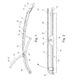
- a wiper device 10 for cleaning a vehicle windscreen (not shown) is depicted in Fig. 1 .
- the wiper device 10 is preferably used on rear vehicle windscreens, although it is also suitable in principle for the area of application of front windscreens.
- the wiper device 10 exhibits a wiper arm 11, which is pivot-mounted on a wiper arm joint 12 in an axis 13.
- a wiper blade 15 is fastened exchangeably on a wiper arm 11, which exhibits a wiper lip 16 on the side facing the vehicle windscreen ( Fig. 2 ).
- the wiper blade 15 is fastened to the wiper arm 11 by means of a wiper blade adapter 18, wherein for the configuration or the nature of the fastening of the wiper blade 15 to the wiper arm 11, a plurality of different constructions or arrangements can be used, as are already known per se from the state of the art, because they are not essential to the invention.
- the wiper blade 15 is pivotably mounted on the wiper arm 11 in a rotation axis 19, so that it is particularly able to adjust to the contour of the vehicle windscreen during movement of the wiper blade 15 over the vehicle windscreen.
- the wiper arm 11 forms a cover 20 which contains the wiper blade 15 over its entire length on the side facing away from the vehicle windscreen, at least in the area of the wiper blade 15.
- the cover 20 has a substantially U-shaped cross-section, at least in the area of the wiper blade 15.
- recesses or openings 22 may be provided.
- the cover 20 exhibits a first part 23 on the side of the wiper arm joint 12, to which a second part 24 is attached on the side facing away from the wiper arm joint 12.
- the second part 24 is pivot-mounted to the first part 23 on an axis 25, wherein the pivoted position of the second part 24, which is assumed when a wiper blade 15 on the wiper arm 11 is to be replaced, is depicted by means of a dotted line in Fig. 1 .
- the arrangement of the axis 25 is such that the wiper blade 15 is accessible to a user in the area of the wiper blade adapter 18 when the second part 24 is pivoted, so that said user can replace the wiper blade 15 on the wiper arm 11 without difficulty.
- the cover 20 is an integral part of the wiper arm 11, such that at least the first part 23 is formed by the wiper arm 11.
- the first part 23 of the wiper arm 11 is configured as a press-bent part.
- the second part 24 of the wiper arm 11 or the cover 20 may likewise be made of metal, as with the wiper arm 11 or the first part 23. It is also possible, however, for the second part 24 to be made of plastic. Furthermore, it is conceivable in principle for the cover 20 also to be configured as a separate part from the wiper arm 11.
- the first part 23 exhibits openings 27 formed in link-type extensions 26 for the pivotable arrangement of the second part 24, with which pin-like extensions 28 of the second part 24 engage.
- a catch connection 30 is configured between the second part 24 and the wiper blade 15.
- the catch connection 30 comprises catch tongues 31, 32 arranged on both longitudinal sides of the wiper blade 15 or else of the cover 20, formed integrally with the cover 20, each of which exhibits a receptacle 33, 34 being U-shaped in cross-section, said receptacles interacting with areas of spring strips 35, 36 projecting laterally from the wiper blade 15 to configure the catch connection 30.
- the catch tongues 31, 32 need simply to be pivoted in the direction of the arrows 37, 38.
- the wiper device 10 exhibits a spray device 40 for applying washing fluid to the vehicle windscreen.
- the spray device 40 comprises at least one, but in the exemplary embodiment depicted in the figures, two washing fluid hoses 41, 42.
- the two washing fluid hoses 41, 42 are conducted within the wiper arm 11 or the cover 20 and connected on the vehicle side to a storage container for the washing fluid.
- the end sections of the two washing fluid hoses 41, 42 facing the wiper blade 15 engage with two plug-like extensions 43, 44 shown in Fig. 3 , which tightly close the washing fluid hoses 41, 42 hydraulically.
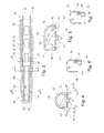
- the two washing fluid hoses 41, 42 are arranged along the two longitudinal sides of the wiper blade 15 or else fastened in the cover 20, wherein the configuration of the washing liquid hoses 41, 42 is preferably in the area of the underside of the cover 20 facing the vehicle windscreen, as is represented by means of Fig. 5 to Fig. 7 . It is moreover evident from Fig. 5 that the two washing fluid hoses 41, 42 are conducted by means of transverse ribs 45, 46 in the cover 20 in the area of the cover 20.
- a fastening of a washing fluid hose 41a or 41b is depicted, in which the washing fluid hose 41a, 41b exhibits a hook-shaped extension 47 on its upper side facing away from the vehicle windscreen, which may either be fitted on a carrier 48 which is formed by a blank in the cover 20 according to Fig. 6 , or on an inwardly curved holding portion 49 of the cover 20 according to Fig. 7 .
- the washing fluid hoses 41, 42 and 41a, 41b exhibit nozzle openings 50 on the side facing the vehicle windscreen, which, as is only evident from Fig. 5 , each form a washing fluid jet 51 when the spray device 40 is operated. It is essential for the nozzle openings 50 only to be formed in the area of the cover 20 or of the wiper blade 15 in which the wiper blade 15 is situated.
- the use of a washing fluid hose 41, 42 and 41a, 41b has the advantage that when the second part 24 of the cover 20 is pivoted into the position shown by a dotted line in Fig. 1 , the washing fluid hose concerned 41, 42 or 41a, 41b can be pivoted without additional measures.
- the nozzle openings 50 can be configured as an integral component of the cover 20, in that the cover 20 exhibits corresponding washing fluid ducts on the underside facing the vehicle windscreen and the nozzle openings 50 are configured as bores in the cover 20, which open into the washing fluid ducts.
- additional provisions must be made in order to achieve pivotability between the two parts 23, 24, i.e. in the dividing point between the two parts 23, 24 in the area of the washing fluid ducts, corresponding sealing measures are taken.
- the heating device 60 comprises at least one heating wire 61, 62, which is arranged within the cross-section of the washing fluid hose 41, 42 or 41a, 41b, as is shown in greatly simplified form in Fig. 3 .
- the heating wires 61, 62 are electrically coupled to a voltage supply.
- the wiper device 10 described thus far may be changed or modified in multifarious ways without deviating from the basic idea underlying the invention.
- This idea is that a spray device 40 is provided in the area of a cover 20 for the wiper blade 15, wherein the wiper blade 15 may be of any design and requires no additional measures in relation to the spray device 40.
- the cover and therefore also the spray device 40 does not extend over the entire length of the wiper blade 15.
- the cover 20 or the spray device 40 should extend at least substantially, i.e. at least by roughly 80%, over the length of the wiper blade 15.
Landscapes
- Engineering & Computer Science (AREA)
- Mechanical Engineering (AREA)
- Water Supply & Treatment (AREA)
- Physics & Mathematics (AREA)
- Fluid Mechanics (AREA)
- Quality & Reliability (AREA)
- Cleaning By Liquid Or Steam (AREA)
- Nozzles (AREA)
- Vehicle Cleaning, Maintenance, Repair, Refitting, And Outriggers (AREA)
- Rear-View Mirror Devices That Are Mounted On The Exterior Of The Vehicle (AREA)
Abstract
Description
- The invention relates to a wiper device for cleaning a vehicle windscreen according to the preamble of Claim 1.
- A wiper device of this kind is disclosed by the applicant in
EP1 918 167 A1 . The known wiper device exhibits a spray device constructed in the form of a hose, which extends spaced parallel to the wiper blade by means of fastening clips which are arranged on the wiper blade of the wiper device. Bores may be made in the hose, which form spray openings for the application of a washing fluid to the vehicle windscreen. The disadvantage of the wiper device known from the aforementioned specification is that when a wiper blade is replaced, the hose has to be separated from the wiper blade in each case and refitted to the new wiper blade. Moreover, the spray device is not protected from the outside environment, which means that leaves or the like can collect between the wiper blade and the spray device, impeding the wiping function of the wiper blade. - Starting from the state of the art, the problem addressed by the invention is that of developing a wiper device for cleaning a vehicle windscreen according to the preamble of Claim 1, such that when a wiper blade is replaced no increased assembly work is required. Moreover, a fitting offering protection wherever possible or a possibly protected arrangement of the spray device in the area of the wiper blade should be facilitated, so that functional impairments, as in the state of the art, can be reliably avoided. This problem is solved according to the invention with a wiper device for cleaning a vehicle windscreen having the characteristics of Claim 1, in that the wiper arm has a hood-shaped cover for the wiper blade, which covers the wiper blade at least substantially over its entire length, and in that the spray device is arranged in the area of the cover.
- Advantageous developments of the wiper device according to the invention for cleaning a vehicle windscreen are set out in the dependent claims. All combinations of at least two of the features disclosed in the claims, the description and/or the figures fall within the framework of the invention.
- In a particularly preferred embodiment of the invention in design terms, it is provided that the spray device is configured as a separate component to the cover in the area of the cover and is connected to the cover. The functional separation referred to between the wiper blade and the spray device is thereby achieved, in that the spray device is connected to the cover, such that when the wiper blade is replaced the spray device can remain on the cover.
- A particularly simply configured spray device is made possible when the spray device comprises at least one washing fluid hose, in which the nozzle openings are constructed as bores. Consequently, no separate components forming the nozzle openings are required; instead, the washing fluid hose providing the washing fluid supply directly forms the nozzle openings.
- In order to prevent washing fluid from escaping from the open end of the washing fluid hose in the area of the wiper blade, it is furthermore proposed in a particularly preferred embodiment that the open end of the washing fluid hose is closed by means of a plug-like holder in the cover. This holder may simultaneously serve to position or fix the washing fluid hose within the cover, so that the holder performs a dual function.
- In an alternative embodiment for using a washing fluid hose it is possible, however, for the spray device to be configured integrally within the cover and to exhibit a washing fluid duct from which the nozzle openings originate. A washing fluid duct of this kind may be achieved when producing the cover, in that said cover is configured as an injection moulded part or as an extruded part, so that the washing fluid duct is formed when the cover is produced by means of a correspondingly designed mould, which means that separate subsequent production stages can be avoided.
- A particularly good spray device function is achieved when the nozzle openings of the spray device are arranged along both longitudinal sides of the wiper blade. In this case, independently of the direction of movement of the wiper blade, washing fluid is applied to the vehicle windscreen right in front of the wiper blade or a wiper lip in each case.
- To enable the wiper blade to be replaced on the wiper arm without difficulty, it is proposed, moreover, that the cover has a part connected to a wiper arm joint, on which a pivotable part is arranged, that the rotation axis of the pivotable part is arranged in the region of the fastening of the wiper blade on the part which is connected to the wiper arm joint, and that the pivotable part is connected to the wiper blade, preferably via a detent connection. A cover design of this kind enables the pivotable part of the cover to be pivoted away in order replace the wiper blade, so that the fastening area of the wiper blade is accessible. The functionality or operating safety of the spray device may be further improved at low outside temperatures if the spray device is constructed so as to be heatable by means of a heating device having a heating wire.
- The wiper device according to the invention has the advantage that it can work with wiper blades of any construction or design, so that wiper blades which can be produced relatively simply and therefore inexpensively from a constructional point of view can be used. Nevertheless, due to the use of the spray device and the optional use of the heating device, the wiper device has a high functional range, which ensures optimal functioning of the wiper device even under relatively difficult environmental conditions. It is preferably provided that the wiper device is arranged in the area of a rear windscreen wiper, as in this case the cover is able to perform the additional protective function for the wiper blade or the spray device. Moreover, wiper devices for front windscreens usually have covers, particularly in the form of the engine bonnet, which restrict the possible installation space for a cover (on the wiper blade) or guarantee adequate protection of the spray device against outside atmospheric influences when the wiper blades are in the stationary position.
- Further features, advantages and details of the invention are obtained from the following description of preferred exemplary embodiments and also with the help of the drawing.
- In the drawing:
- Fig. 1
- shows a simplified side view of a wiper device according to the invention for cleaning a vehicle windscreen, in which part of a cover is depicted in different positions,
- Fig. 2
- shows a longitudinal section through the wiper device according to
Fig. 1 in the area of the wiper blade, - Fig. 3
- shows a sectional top view of the wiper device according to
Fig. 2 , - Fig. 4
- shows a section on the plane IV-IV in
Fig. 3 , - Fig. 5
- shows a section on the plane V-V in
Fig. 3 and - Fig. 6 and 7
- show various representations for fastening a spray device in the area of a cover in cross-section.
- The same components or components with the same function are denoted using the same reference numbers in the figures.
- A
wiper device 10 for cleaning a vehicle windscreen (not shown) is depicted inFig. 1 . Thewiper device 10 is preferably used on rear vehicle windscreens, although it is also suitable in principle for the area of application of front windscreens. - The
wiper device 10 exhibits awiper arm 11, which is pivot-mounted on a wiper arm joint 12 in anaxis 13. Awiper blade 15 is fastened exchangeably on awiper arm 11, which exhibits awiper lip 16 on the side facing the vehicle windscreen (Fig. 2 ). Thewiper blade 15 is fastened to thewiper arm 11 by means of awiper blade adapter 18, wherein for the configuration or the nature of the fastening of thewiper blade 15 to thewiper arm 11, a plurality of different constructions or arrangements can be used, as are already known per se from the state of the art, because they are not essential to the invention. All that is important for the function of thewiper blade 15 is that it is pivotably mounted on thewiper arm 11 in arotation axis 19, so that it is particularly able to adjust to the contour of the vehicle windscreen during movement of thewiper blade 15 over the vehicle windscreen. - The
wiper arm 11 forms acover 20 which contains thewiper blade 15 over its entire length on the side facing away from the vehicle windscreen, at least in the area of thewiper blade 15. As is particularly evident fromFig. 4 and Fig. 5 , thecover 20 has a substantially U-shaped cross-section, at least in the area of thewiper blade 15. Along theupper side 21 of thecover 20, recesses oropenings 22 may be provided. Thecover 20 exhibits afirst part 23 on the side of the wiper arm joint 12, to which asecond part 24 is attached on the side facing away from the wiper arm joint 12. Thesecond part 24 is pivot-mounted to thefirst part 23 on anaxis 25, wherein the pivoted position of thesecond part 24, which is assumed when awiper blade 15 on thewiper arm 11 is to be replaced, is depicted by means of a dotted line inFig. 1 . The arrangement of theaxis 25 is such that thewiper blade 15 is accessible to a user in the area of thewiper blade adapter 18 when thesecond part 24 is pivoted, so that said user can replace thewiper blade 15 on thewiper arm 11 without difficulty. - In the exemplary embodiment shown, the
cover 20 is an integral part of thewiper arm 11, such that at least thefirst part 23 is formed by thewiper arm 11. In this case, thefirst part 23 of thewiper arm 11 is configured as a press-bent part. Thesecond part 24 of thewiper arm 11 or thecover 20 may likewise be made of metal, as with thewiper arm 11 or thefirst part 23. It is also possible, however, for thesecond part 24 to be made of plastic. Furthermore, it is conceivable in principle for thecover 20 also to be configured as a separate part from thewiper arm 11. - As is most clearly evident from
Fig. 3 , thefirst part 23exhibits openings 27 formed in link-type extensions 26 for the pivotable arrangement of thesecond part 24, with which pin-like extensions 28 of thesecond part 24 engage. In order to securely connect thesecond part 24 to thewiper blade 15 with thesecond part 24 in the operating position, so as to prevent thesecond part 24 from automatically moving into the position which enables thewiper blade 15 to be replaced, acatch connection 30 is configured between thesecond part 24 and thewiper blade 15. - As can be seen from
Fig. 3 and Fig. 4 taken together, thecatch connection 30 comprisescatch tongues wiper blade 15 or else of thecover 20, formed integrally with thecover 20, each of which exhibits areceptacle spring strips wiper blade 15 to configure thecatch connection 30. To release thecatch connection 30, thecatch tongues arrows - It is provided according to the invention that the
wiper device 10 exhibits aspray device 40 for applying washing fluid to the vehicle windscreen. Thespray device 40 comprises at least one, but in the exemplary embodiment depicted in the figures, twowashing fluid hoses washing fluid hoses wiper arm 11 or thecover 20 and connected on the vehicle side to a storage container for the washing fluid. The end sections of the twowashing fluid hoses wiper blade 15 engage with two plug-like extensions Fig. 3 , which tightly close thewashing fluid hoses washing fluid hoses wiper blade 15 or else fastened in thecover 20, wherein the configuration of thewashing liquid hoses cover 20 facing the vehicle windscreen, as is represented by means ofFig. 5 to Fig. 7 . It is moreover evident fromFig. 5 that the twowashing fluid hoses transverse ribs cover 20 in the area of thecover 20. - In
Fig. 6 and Fig. 7 , by contrast, a fastening of awashing fluid hose washing fluid hose extension 47 on its upper side facing away from the vehicle windscreen, which may either be fitted on acarrier 48 which is formed by a blank in thecover 20 according toFig. 6 , or on an inwardly curved holdingportion 49 of thecover 20 according toFig. 7 . - The
washing fluid hoses exhibit nozzle openings 50 on the side facing the vehicle windscreen, which, as is only evident fromFig. 5 , each form awashing fluid jet 51 when thespray device 40 is operated. It is essential for thenozzle openings 50 only to be formed in the area of thecover 20 or of thewiper blade 15 in which thewiper blade 15 is situated. The use of awashing fluid hose second part 24 of thecover 20 is pivoted into the position shown by a dotted line inFig. 1 , the washing fluid hose concerned 41, 42 or 41a, 41b can be pivoted without additional measures. - As a variation to the exemplary embodiments of the
spray device 40 shown in the figures, it is also conceivable for thenozzle openings 50 to be configured as an integral component of thecover 20, in that thecover 20 exhibits corresponding washing fluid ducts on the underside facing the vehicle windscreen and thenozzle openings 50 are configured as bores in thecover 20, which open into the washing fluid ducts. In this case, however, additional provisions must be made in order to achieve pivotability between the twoparts parts - In addition, it may be provided that alongside the spray device 40 a
heating device 60 is also provided, which serves to safeguard the functioning of thespray device 40 at low temperatures. For this purpose, theheating device 60, as can only be seen fromFig. 3 , comprises at least oneheating wire washing fluid hose Fig. 3 . Theheating wires - The
wiper device 10 described thus far may be changed or modified in multifarious ways without deviating from the basic idea underlying the invention. This idea is that aspray device 40 is provided in the area of acover 20 for thewiper blade 15, wherein thewiper blade 15 may be of any design and requires no additional measures in relation to thespray device 40. As a variation to the invention, it is also conceivable that the cover and therefore also thespray device 40 does not extend over the entire length of thewiper blade 15. However, thecover 20 or thespray device 40 should extend at least substantially, i.e. at least by roughly 80%, over the length of thewiper blade 15. -
- 10
- Wiper device
- 11
- Wiper arm
- 12
- Wiper arm joint
- 13
- Axis
- 15
- Wiper blade
- 16
- Wiper lip
- 18
- Wiper blade adapter
- 19
- Rotation axis
- 20
- Cover
- 21
- Upper side
- 22
- Opening
- 23
- First part
- 24
- Second part
- 25
- Axis
- 26
- Link-like extension
- 27
- Opening
- 28
- Pin-like extension
- 30
- Catch connection
- 31
- Catch tongue
- 32
- Catch tongue
- 33
- U-shaped receptacle
- 34
- U-shaped receptacle
- 35
- Spring strip
- 36
- Spring strip
- 37
- Arrow
- 38
- Arrow
- 40
- Spray device
- 41
- Washing fluid hose
- 41a
- Washing fluid hose
- 41b
- Washing fluid hose
- 42
- Washing fluid hose
- 43
- Plug-like extension
- 44
- Plug-like extension
- 45
- Transverse rib
- 46
- Transverse rib
- 47
- Hook-shaped extension
- 48
- Carrier
- 49
- Holding segment
- 50
- Nozzle opening
- 51
- Washing fluid jet
- 60
- Heating device
- 61
- Heating wire
- 62
- Heating wire
Claims (10)
- A wiper device (10) for cleaning a vehicle window, with a wiper blade (15), which is fastened exchangeably on a wiper arm (11), wherein along the wiper blade (15) an elongatedly constructed spray device (40) having several nozzle openings (50) is arranged for applying a washing fluid onto the vehicle window, which is constructed as a separate component from the wiper blade (15),
characterized in that
the wiper arm (11) has a hood-shaped cover (20) for the wiper blade (15), which covers the wiper blade (15) at least substantially over its entire length, and that the spray device (40) is arranged in the region of the cover (20). - The wiper device according to Claim 1,
characterized in that
in the region of the cover (20) the spray device (40) is constructed as a separate component from the cover (20) and is connected with the cover (20). - The wiper device according to Claim 2,
characterized in that
the spray device (40) comprises at least one washing fluid hose (41, 41a, 41b, 42) in which the nozzle openings (50) are constructed as bores. - The wiper device according to Claim 3,
characterized in that
the open end of the washing fluid hose (41, 42) is closed by means of a plug-like holder (43, 44) in the cover (20). - The wiper device according to Claim 1,
characterized in that
the spray device (40) is constructed in one piece in the cover and has a washing fluid duct from which the nozzle openings originate. - The wiper device according to one of Claims 1 to 5,
characterized in that
the nozzle openings (50) of the spray device (40) are arranged along both longitudinal sides of the wiper blade (15). - The wiper device according to one of Claims 1 to 6,
characterized in that
the spray device (40) is arranged on the inner side of the cover (20) on the lower region facing the vehicle window. - The wiper device according to one of Claims 1 to 7,
characterized in that
the cover (20) has a part (23) connected with a wiper arm joint (12) and on which a pivotable part (24) is arranged, that the rotation axis (25) of the pivotable part (24) is arranged in the region of the fastening of the wiper blade (15) on the part (23) which is connected with the wiper arm joint (12), and that the pivotable part (24) is connected with the wiper blade (15) preferably via a detent connection (30). - The wiper device according to Claim 8,
characterized in that
the detent connection (30) embraces spring strips (35, 36) of the wiper blade (15) by means of detent tongues (31, 32). - The wiper device according to one of Claims 1 to 9,
characterized in that
the spray device (40) is constructed so as to be heatable by means of a heating device (60) having a heating wire (61, 62).
Applications Claiming Priority (1)
| Application Number | Priority Date | Filing Date | Title |
|---|---|---|---|
| DE102011055962A DE102011055962A1 (en) | 2011-12-02 | 2011-12-02 | Wiper device for cleaning a vehicle window |
Publications (2)
| Publication Number | Publication Date |
|---|---|
| EP2599675A2 true EP2599675A2 (en) | 2013-06-05 |
| EP2599675A3 EP2599675A3 (en) | 2017-07-12 |
Family
ID=47263111
Family Applications (1)
| Application Number | Title | Priority Date | Filing Date |
|---|---|---|---|
| EP12193346.9A Withdrawn EP2599675A3 (en) | 2011-12-02 | 2012-11-20 | Wiper device for cleaning a vehicle windscreen |
Country Status (11)
| Country | Link |
|---|---|
| US (1) | US20130139342A1 (en) |
| EP (1) | EP2599675A3 (en) |
| JP (1) | JP2013116733A (en) |
| KR (1) | KR20130062232A (en) |
| CN (1) | CN103129527B (en) |
| AR (1) | AR089043A1 (en) |
| BR (1) | BR102012030630A2 (en) |
| CA (1) | CA2796960A1 (en) |
| DE (1) | DE102011055962A1 (en) |
| MX (1) | MX2012014018A (en) |
| RU (1) | RU2012151523A (en) |
Cited By (1)
| Publication number | Priority date | Publication date | Assignee | Title |
|---|---|---|---|---|
| FR3099447A1 (en) * | 2019-07-31 | 2021-02-05 | Valeo Systemes D'essuyage | Drive arm of a wiping system for a wiping surface |
Families Citing this family (21)
| Publication number | Priority date | Publication date | Assignee | Title |
|---|---|---|---|---|
| US9937899B2 (en) * | 2013-10-28 | 2018-04-10 | Asmo Co., Ltd. | Wiper arm and vehicle wiper apparatus equipped therewith |
| CN104129364A (en) * | 2014-06-23 | 2014-11-05 | 潘纪鸿 | Windscreen wiper for cleaning automobile windshield |
| EP3002167A1 (en) * | 2014-10-02 | 2016-04-06 | Valeo Systèmes d'Essuyage | Device for a vehicle window wiper arm and method for installing the same |
| FR3029477B1 (en) * | 2014-12-09 | 2018-03-02 | Valeo Systemes D'essuyage | DEVICE FOR SPRAYING A WASHING LIQUID FOR A BRUSH ARM FOR A WINDOW WINDING SYSTEM OF A GLASS OF A MOTOR VEHICLE |
| DE102015114930A1 (en) * | 2015-09-07 | 2017-03-09 | Valeo Systèmes d'Essuyage | Cleaning device for cleaning a vehicle window |
| DE102015114931A1 (en) * | 2015-09-07 | 2017-03-09 | Valeo Systèmes d'Essuyage | Wiper arm for cleaning a vehicle window |
| KR101745204B1 (en) * | 2015-12-11 | 2017-06-08 | 현대자동차주식회사 | Wiper as one body with washer |
| FR3066971B1 (en) * | 2017-06-05 | 2020-10-23 | Valeo Systemes Dessuyage | DEVICE FOR MAINTAINING A TIMONERIE OF A WIPING MECHANISM, BEARING OF A TIMONERIE, ASSOCIATED TIMONERIE SUB-ASSEMBLY AND TIMONERIE, AND METHOD OF INSTALLING A HOLDING DEVICE ON A TIMONERIE |
| DE102017119223A1 (en) * | 2017-08-23 | 2019-02-28 | Valeo Wischersysteme Gmbh | Wiper arm device for motor vehicles |
| CN109305140A (en) * | 2018-10-30 | 2019-02-05 | 安徽安庆市沙氏汽车配件有限公司 | A kind of car automatic flushing device |
| DE102018222242A1 (en) * | 2018-12-19 | 2020-06-25 | Robert Bosch Gmbh | Wiper blade, in particular for a motor vehicle |
| JP7069074B2 (en) * | 2019-03-20 | 2022-05-17 | 本田技研工業株式会社 | Transport equipment |
| DE102019110079B4 (en) * | 2019-04-16 | 2025-12-11 | A. Raymond Et Cie | Wind deflector for a car's windshield wiper system |
| CN110001588A (en) * | 2019-04-24 | 2019-07-12 | 厦门宇进塑胶制品有限公司 | A kind of two-strip windshield wiper sheath |
| JP7236972B2 (en) * | 2019-09-26 | 2023-03-10 | 株式会社ミツバ | wiper arm |
| JP7236971B2 (en) * | 2019-09-26 | 2023-03-10 | 株式会社ミツバ | wiper arm |
| CN111098827A (en) * | 2020-01-11 | 2020-05-05 | 浙江胜华波电器股份有限公司 | Nozzle spraying device with matched sleeve |
| DE102020200349A1 (en) * | 2020-01-14 | 2021-07-15 | Robert Bosch Gesellschaft mit beschränkter Haftung | Windshield wiper device, in particular wiper arm adapter device, wiper arm with the windshield wiper device and windshield wiper with the windshield wiper device |
| DE102020210447A1 (en) * | 2020-08-18 | 2022-02-24 | Robert Bosch Gesellschaft mit beschränkter Haftung | Wiper blade device for a windscreen wiper with a spray function |
| CN215590689U (en) * | 2020-11-26 | 2022-01-21 | 台州法雷奥温岭汽车零部件有限公司 | Wiper arm, wiper and vehicle |
| KR102461203B1 (en) * | 2021-07-07 | 2022-10-28 | 장수동 | Wiper apparatus |
Citations (3)
| Publication number | Priority date | Publication date | Assignee | Title |
|---|---|---|---|---|
| FR2653083A1 (en) * | 1989-10-13 | 1991-04-19 | Journee Paul Sa | Windscreen wiper equipped with a fairing device, particularly for a motor vehicle |
| FR2744973A1 (en) * | 1996-02-16 | 1997-08-22 | Journee Paul Sa | MOTOR VEHICLE WINDSCREEN WIPER PROVIDED WITH A TRIM HOOD CARRIED BY A BRUSH JOINT CONNECTOR ON THE WIPER ARM |
| EP1918167A1 (en) | 2006-10-30 | 2008-05-07 | Valeo Systèmes d'Essuyage | A device for attachment to a wiper blade |
Family Cites Families (17)
| Publication number | Priority date | Publication date | Assignee | Title |
|---|---|---|---|---|
| US3574881A (en) * | 1969-06-16 | 1971-04-13 | Reinhold Temple | Heated windshield wiper-spray assembly |
| DE2311293C3 (en) * | 1973-03-07 | 1975-10-30 | Swf-Spezialfabrik Fuer Autozubehoer Gustav Rau Gmbh, 7120 Bietigheim | Wiper blade for windshield wiper systems for vehicles, in particular motor vehicles |
| DE3424729A1 (en) * | 1984-07-05 | 1986-02-06 | SWF Auto-Electric GmbH, 7120 Bietigheim-Bissingen | Wiper lever, in particular for the window wiper systems of motor vehicles |
| FR2682340B1 (en) * | 1991-10-14 | 1993-12-03 | Valeo Systemes Essuyage | CARENE WINDOW WIPER, PARTICULARLY FOR MOTOR VEHICLES. |
| DE9320075U1 (en) * | 1993-12-31 | 1994-02-24 | Zanke, U., Prof. Dr.-Ing.habil., 30826 Garbsen | Windshield washer |
| DE19829759A1 (en) * | 1998-07-03 | 2000-01-05 | Itt Mfg Enterprises Inc | Wiper arm for a system for cleaning a window |
| DE19914122A1 (en) * | 1999-03-27 | 2000-09-28 | Volkswagen Ag | Windscreen washer for vehicle, with hollow spoiler having spray jets integrated into its wall |
| JP3869232B2 (en) * | 2001-04-20 | 2007-01-17 | アスモ株式会社 | Wiper arm |
| JP4580124B2 (en) * | 2001-07-11 | 2010-11-10 | アスモ株式会社 | Wiper arm |
| US7603742B2 (en) * | 2004-01-30 | 2009-10-20 | Asmo Co., Ltd. | Wiper blade and wiper system having the same |
| DE102004056835B4 (en) * | 2004-11-25 | 2018-02-15 | Valeo Systèmes d'Essuyage | wiper blade |
| FR2929215B1 (en) * | 2008-03-26 | 2010-04-02 | Valeo Systemes Dessuyage | WIPER BLADE FOR VEHICLE WINDOWS |
| DE102008042405A1 (en) * | 2008-04-17 | 2009-10-22 | Robert Bosch Gmbh | Wiper blade and a sprayer |
| DE102009017990B4 (en) * | 2009-04-21 | 2022-04-07 | Valeo Systèmes d'Essuyage | flat wiper blade |
| DE102009059119B4 (en) * | 2009-12-19 | 2014-11-13 | Daimler Ag | Connecting arrangement and method for arranging a wiper blade on a wiper arm |
| DE102009059118A1 (en) * | 2009-12-19 | 2011-06-22 | Daimler AG, 70327 | Wiper system and method for operating a wiper system for a motor vehicle |
| DE102010007557A1 (en) * | 2010-02-10 | 2011-08-11 | Valeo Wischersysteme GmbH, 74321 | Wiper device for vehicle windows and wiper blade with a heating device |
-
2011
- 2011-12-02 DE DE102011055962A patent/DE102011055962A1/en not_active Withdrawn
-
2012
- 2012-11-20 EP EP12193346.9A patent/EP2599675A3/en not_active Withdrawn
- 2012-11-21 CA CA2796960A patent/CA2796960A1/en not_active Abandoned
- 2012-11-29 KR KR1020120137030A patent/KR20130062232A/en not_active Withdrawn
- 2012-11-30 AR ARP120104503A patent/AR089043A1/en unknown
- 2012-11-30 BR BR102012030630-1A patent/BR102012030630A2/en not_active IP Right Cessation
- 2012-11-30 JP JP2012262695A patent/JP2013116733A/en active Pending
- 2012-11-30 US US13/690,927 patent/US20130139342A1/en not_active Abandoned
- 2012-11-30 MX MX2012014018A patent/MX2012014018A/en not_active Application Discontinuation
- 2012-11-30 RU RU2012151523/11A patent/RU2012151523A/en not_active Application Discontinuation
- 2012-12-03 CN CN201210598727.5A patent/CN103129527B/en not_active Expired - Fee Related
Patent Citations (3)
| Publication number | Priority date | Publication date | Assignee | Title |
|---|---|---|---|---|
| FR2653083A1 (en) * | 1989-10-13 | 1991-04-19 | Journee Paul Sa | Windscreen wiper equipped with a fairing device, particularly for a motor vehicle |
| FR2744973A1 (en) * | 1996-02-16 | 1997-08-22 | Journee Paul Sa | MOTOR VEHICLE WINDSCREEN WIPER PROVIDED WITH A TRIM HOOD CARRIED BY A BRUSH JOINT CONNECTOR ON THE WIPER ARM |
| EP1918167A1 (en) | 2006-10-30 | 2008-05-07 | Valeo Systèmes d'Essuyage | A device for attachment to a wiper blade |
Cited By (1)
| Publication number | Priority date | Publication date | Assignee | Title |
|---|---|---|---|---|
| FR3099447A1 (en) * | 2019-07-31 | 2021-02-05 | Valeo Systemes D'essuyage | Drive arm of a wiping system for a wiping surface |
Also Published As
| Publication number | Publication date |
|---|---|
| EP2599675A3 (en) | 2017-07-12 |
| AR089043A1 (en) | 2014-07-23 |
| CN103129527A (en) | 2013-06-05 |
| JP2013116733A (en) | 2013-06-13 |
| DE102011055962A1 (en) | 2013-06-06 |
| RU2012151523A (en) | 2014-06-10 |
| KR20130062232A (en) | 2013-06-12 |
| CN103129527B (en) | 2017-11-03 |
| BR102012030630A2 (en) | 2014-03-04 |
| US20130139342A1 (en) | 2013-06-06 |
| CA2796960A1 (en) | 2013-06-02 |
| MX2012014018A (en) | 2013-06-17 |
Similar Documents
| Publication | Publication Date | Title |
|---|---|---|
| US20130139342A1 (en) | Wiper device for cleaning a vehicle windscreen | |
| EP2421730B1 (en) | Flat wiper blade | |
| US9021651B2 (en) | Wiper device, in particular a motor vehicle windshield wiper device | |
| JP4681647B2 (en) | A device for jointly connecting wiper blades with windshield wiper wiper arms | |
| US8381348B2 (en) | Wiper arm/wiper blade connection and wiper blade | |
| US8186002B2 (en) | Device for the pivoting connection of a wiper blade to a wiper arm of a windscreen wiper | |
| KR101163613B1 (en) | Covered wiper for vehicle window | |
| CN101166653A (en) | wiper blade | |
| US20220212632A1 (en) | Wind deflector for a windscreen wiper system of a motor vehicle | |
| CN104379415B (en) | Windshield wiper arm and manufacturing method thereof | |
| US20200231127A1 (en) | A windscreen wiper arm | |
| US20130298347A1 (en) | Device for the articulated connection of a flat-bar wiper blade to a wiper arm | |
| WO2012055746A1 (en) | Wiper blade for a wiper device for the cleaning of vehicle windows and wiper device | |
| JP5665884B2 (en) | Wiper blade unit | |
| RU2604916C2 (en) | Windscreen wiper brush | |
| FR3004684A1 (en) | ICE WIPER BLADE DEVICE COMPRISING AT LEAST ONE END CAP UNIT | |
| US11858474B2 (en) | Wind deflector for a window wiper system of a motor vehicle | |
| KR101822598B1 (en) | End cap arrangement | |
| US20230356695A1 (en) | Wind deflector for a windscreen wiper system of a motor vehicle | |
| EP3676135B1 (en) | A windscreen wiper device | |
| KR20010034288A (en) | Wiper element for cleaning motor vehicle windows | |
| FR3027575A1 (en) | WIPER BLADE DEVICE WITH ADAPTER AND METHOD FOR CONNECTING ADAPTER TO ELASTIC RAIL | |
| JP2012148588A (en) | Wiper blade |
Legal Events
| Date | Code | Title | Description |
|---|---|---|---|
| PUAI | Public reference made under article 153(3) epc to a published international application that has entered the european phase |
Free format text: ORIGINAL CODE: 0009012 |
|
| 17P | Request for examination filed |
Effective date: 20121120 |
|
| AK | Designated contracting states |
Kind code of ref document: A2 Designated state(s): AL AT BE BG CH CY CZ DE DK EE ES FI FR GB GR HR HU IE IS IT LI LT LU LV MC MK MT NL NO PL PT RO RS SE SI SK SM TR |
|
| AX | Request for extension of the european patent |
Extension state: BA ME |
|
| PUAL | Search report despatched |
Free format text: ORIGINAL CODE: 0009013 |
|
| AK | Designated contracting states |
Kind code of ref document: A3 Designated state(s): AL AT BE BG CH CY CZ DE DK EE ES FI FR GB GR HR HU IE IS IT LI LT LU LV MC MK MT NL NO PL PT RO RS SE SI SK SM TR |
|
| AX | Request for extension of the european patent |
Extension state: BA ME |
|
| RIC1 | Information provided on ipc code assigned before grant |
Ipc: B60S 1/38 20060101ALI20170608BHEP Ipc: B60S 1/52 20060101AFI20170608BHEP |
|
| STAA | Information on the status of an ep patent application or granted ep patent |
Free format text: STATUS: EXAMINATION IS IN PROGRESS |
|
| 17Q | First examination report despatched |
Effective date: 20181218 |
|
| STAA | Information on the status of an ep patent application or granted ep patent |
Free format text: STATUS: THE APPLICATION IS DEEMED TO BE WITHDRAWN |
|
| 18D | Application deemed to be withdrawn |
Effective date: 20201009 |