EP2599674A2 - Liquid container for a motor vehicle - Google Patents
Liquid container for a motor vehicle Download PDFInfo
- Publication number
- EP2599674A2 EP2599674A2 EP12191453.5A EP12191453A EP2599674A2 EP 2599674 A2 EP2599674 A2 EP 2599674A2 EP 12191453 A EP12191453 A EP 12191453A EP 2599674 A2 EP2599674 A2 EP 2599674A2
- Authority
- EP
- European Patent Office
- Prior art keywords
- container
- liquid
- liquid container
- container according
- cavity
- Prior art date
- Legal status (The legal status is an assumption and is not a legal conclusion. Google has not performed a legal analysis and makes no representation as to the accuracy of the status listed.)
- Withdrawn
Links
Images


Classifications
-
- B—PERFORMING OPERATIONS; TRANSPORTING
- B60—VEHICLES IN GENERAL
- B60S—SERVICING, CLEANING, REPAIRING, SUPPORTING, LIFTING, OR MANOEUVRING OF VEHICLES, NOT OTHERWISE PROVIDED FOR
- B60S1/00—Cleaning of vehicles
- B60S1/02—Cleaning windscreens, windows or optical devices
- B60S1/46—Cleaning windscreens, windows or optical devices using liquid; Windscreen washers
- B60S1/48—Liquid supply therefor
- B60S1/50—Arrangement of reservoir
Definitions
- Such liquid containers are known, for example, for storing cleaning liquid for windshield, headlights or the like in motor vehicles.
- Depending on the desired capacity of the liquid container correspondingly different sizes variants of the container are manufactured.
- separate productions are required for each capacity.
- the production of such containers made of plastic by means of a blow molding or injection molding process.
- two half-shells are injection-molded and then joined together.
- both half-shells are usually adapted to the respective variant.
- four cavities are usually required to provide two different capacities in the injection molding process.
- two different blow-molding tools generally have to be produced.
- the need for different capacities of the liquid container may have various causes. Basically, the entrainment of the least possible cleaning liquid is desired for energy saving reasons, since each kilogram additionally leads to a vehicle to increased fuel consumption. On the other hand, a very small capacity is uncomfortable, as is often required refilling of the container. In particular, in wintry road conditions, this also results in a safety risk, since with appropriate weather in a very short time, a high consumption of cleaning fluid may arise, for example, to ensure a clear view through the windshield of the vehicle. A very big one Consumption of cleaning fluid is present in particular if the vehicle has a headlight cleaning system, which causes an additional need for cleaning fluid. Since headlight cleaning systems usually do not belong to the standard equipment of a vehicle, both liquid container for cleaning liquid with smaller capacity (equipment without headlight cleaning system) and with large capacity (headlight cleaning system) are therefore often required for one and the same vehicle series.
- the invention has for its object to provide a liquid container with the features described above, which takes into account different equipment variants of a vehicle and at the same time is inexpensive to produce.
- this object is achieved in that at least two adjusting positions having adjusting device is provided which ensures the formation of a gas cushion, preferably air cushion within the container cavity and thus only a partial maximum filling of the container cavity in at least one parking position.
- at least one setting position is adjustable, which prevents complete filling of the container cavity with liquid.
- the liquid container according to the invention can be provided, on the one hand, in a first setting position with a low liquid capacity, as is expedient, for example, for storing cleaning liquid for vehicles without headlight cleaning system.
- the second setting position allows a larger capacity by, for example, virtually completely possible filling of the container, as it is useful, for example, for vehicles with headlight cleaning systems.
- the gas cushion prevents complete filling of the container with liquid.
- the tube is followed by a downwardly extending into the container cavity pipe, which serves for filling liquid through the opening into the container cavity, wherein the formation of the air cushion at a certain liquid immersion height of the projecting into the container cavity lower open end of the Piping is done.
- This measure is based on the knowledge that the amount of liquid that can actually be filled into the container depends on whether there is a possibility of venting the container cavity. In a dive of the pipeline can no longer be vented through this, so that it can come in the immersion state of the pipe in principle to form a gas cushion according to the invention by the air still in the container.
- the lower open end of the tubing is positioned so that it is fully submerged at a 90% fill level.
- Degree of filling here means the ratio of the volume of liquid filled in the container cavity to the total volume of the container cavity.
- the lower end of the pipeline is at a fill level of 75%, e.g. 60%, in particular 50% completely submerged. This ensures that there is a marked difference between the adjustable smaller and larger capacity, which is e.g. the significantly different fluid requirements in a vehicle without or with headlight cleaning system account.
- the liquid capacity of the container cavity may be adjustable in stages, eg over the maximum liquid level in the container cavity.
- the adjusting device on a vent tube which projects into the container cavity and the container wall passes through airtight.
- the vent tube is usually flexible, ie hose-like, formed. In the context of the invention, however, is also a rigid vent tube. Conveniently, the vent tube is slidably disposed in the passage of the container wall.
- the capacity of the container can be so influenced by a simple vertical displacement of the vent line, wherein a far pushed into the container cavity vent tube causes the same early dipping.
- the formation of the air cushion according to the invention thus takes place in this case even at a low degree of filling through the air still in the container cavity, which can no longer escape.
- the smallest adjustable capacity thus results from a positioning of the lower end of the vent tube at the level of the lower end of the pipeline. With only slightly inserted vent tube, however, the formation of the air cushion takes place only at a higher liquid level in the container, so that there is a larger capacity in this case.
- the vent tube passes through the container wall substantially horizontally aligned and is bent within the container so that its lower end portion is substantially vertically aligned.
- the vent tube may be guided in the passage at at least one further point within the container. This guide is used e.g. for the aforementioned deflection of the ventilation tube from its horizontal orientation outside the container for vertical alignment at the lower end of the vent tube.
- the outlet opening of the vent tube is suitably higher than the opening for container filling. This avoids that liquid can escape via the vent tube from the container, thus preventing unnoticed overfilling of the container.
- it can be arranged in the vent tube and a float valve, which closes upon contact with the ascending in the vent tube liquid.
- the venting tube can have, at least in some areas, a structured outer contour which cooperates at least indirectly with the container wall for the stepwise adjustment of the insertion length.
- the insertion length can - as described above - the beginning of the dipping of the vent pipe and thus the maximum filling of the container cavity can be adjusted.
- the vent tube may at least partially be formed as a corrugated pipe, wherein correspondingly each wave crest or each trough a certain maximum liquid level is assigned.
- the vent tube expediently has an inner diameter of at least 3 mm, preferably at least 5 mm.
- the vent tube may have on its outer wall at least one mark for determining the set capacity, which correlates with the corresponding insertion length. This marking is expediently located in the region of the passage just outside the container, provided that the associated capacity volume is set.
- the adjusting device comprises a closure device for selectively closing a second opening in the upper region the container wall.
- the venting device optionally allows or prevents venting via the second opening on the container wall.
- an air cushion forms, which prevents further filling of the container with liquid.
- the second opening is open, the air can escape from the container through the second opening, even when the pipeline is submerged, so that further filling of the container is possible.
- the closure device can be designed, for example, as a stopper with which an airtight closure of the second opening is possible.
- a float valve is provided below the second opening, which is integrated, for example, in a short, projecting into the container cavity tube.
- the float valve closes, thereby preventing leakage of liquid through the second opening and thus unnoticed overfilling of the container.
- a separate vent line is expediently arranged on the pipeline, which is also immersed gemeisam with the pipe during the filling process. As a result, a uniform filling is ensured.
- This vent line can in particular - as already practiced in many prior art - be integrated into the pipeline as a "tube-in-tube construction".
- the gas cushion to be provided in another way, e.g. via an inflatable within the container cavity balloon as adjusting device is provided. It is also conceivable to adjust the liquid capacity via a vertically displaceable pipeline as an adjusting device, wherein the adjustment of the capacity can be done in this case on the dipping of the pipeline.
- the container cavity may have a significantly greater extent in the vertical direction than in the horizontal direction.
- the vertical extent of the container cavity is more than 50% greater than its horizontal extent. This vertical orientation makes it possible to adjust the capacity very finely by means of the device according to the invention over the maximum possible height of the liquid in the container cavity.
- the container wall can be made of injection-molded or blow-molded plastic. In the injection-molded design, the vent pipe is expediently mounted prior to welding the two container shells.
- the container wall can also Have at least one connection device for attachment of at least one further motor vehicle component. Since the liquid container, regardless of the equipment of the respective vehicle always one and the same geometry, this results montagetechnische advantages.
- the connection of the motor vehicle component can thus be constructed independent of equipment. In the prior art, however, which depending on the equipment variant, the use of different liquid containers to the standard, this is not or only to a limited extent (eg using appropriate adapter) possible because the outer contour of the different liquid containers usually varies significantly.
- the invention further relates to a liquid container with a liquid feed pump and / or a fill level sensor according to claim 14 and a motor vehicle with a liquid container according to claim 15.
- the FIG. 1 a shows a liquid container for a motor vehicle, which serves to store cleaning liquid 1.
- the container has a container wall 2 which defines an inner container cavity 3 and has at least one opening 4 for container filling. Adjoining the opening 4 is a pipe 5 which extends downwards into the container cavity 3 and which is inserted into the container cavity 3 as a separate component.
- the pipe 5 is used for filling of cleaning liquid 1 through the opening 4 in the container cavity 3.
- the cleaning liquid contains in addition to water cleaning active substances and antifreeze.
- a plurality of adjusting positions having adjusting device 6 is provided, wherein the adjusting positions are each assigned a specific liquid capacity of the container.
- the adjusting device 6 ensures only a partial maximum filling of the container cavity 3 with liquid 1.
- the lower end of the pipe 5 is positioned so that it is just submerged at a degree of filling of 50%.
- the capacity can be adjusted by means of the adjusting device 6 in a range of about 50 to about 100% degree of filling.
- the adjusting device 6 a flexible vent pipe 9, which projects into the container cavity 3 and the container wall 2 airtight souvantt.
- the vent tube 9 is in this case in the passage 10 of the container 2 axially displaceable.
- the outlet opening 19 of the vent pipe 9 is higher than the opening 4. This avoids that liquid 1 exits through the vent pipe 9 from the container, thus preventing unnoticed overfilling of the container.
- the vent pipe 9 is now inserted so far that its lower open end 11 is positioned approximately at the same height as the open end 7 of the pipe 5.
- the container wall 2 consists of two halves of injection-molded plastic which are welded together, wherein the vent tube 11 is mounted before welding.
- the vent tube 9 passes through the container wall 2 substantially horizontally and is bent inside the container so that its lower open end 11 is substantially vertically aligned.
- the guide 12 is molded onto one of the two halves of the container wall 2.
- the vent tube 9 has an inner diameter of at least 3 mm.
- the opening 4 in the container wall 2 can be closed with a clip-on cover 13.
- the container cavity 3 has a significantly greater extent in the vertical direction than in the horizontal direction.
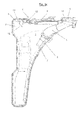
- FIG. 2 shows a section of the in the FIGS. 1a-c
- the vent pipe 11 is partially formed as a corrugated pipe. Accordingly, over each wave trough or each wave mountain a certain insertion depth of the vent tube 11 is set in the container cavity 3 and hereby the liquid capacity of the container can be adjusted stepwise.
- the outer contour of the vent tube 11 cooperates with the molded-on to the container wall 2 guide 12. In the region of the passage 10, however, the vent pipe 11 is formed smooth to ensure a secure seal against the air in the container cavity 3.
- this closure device 14 is designed as a stopper, which is provided with a catching band 16, which is preferably formed integrally with the container wall 2 and connected to the container wall 2.
- the plug 14 is pressed into the second opening 15 and closes them airtight. If, by filling the container with liquid 1, a dip of the lower open end 7 of the pipeline 5 begins, no further air can escape from the container and the filling process is terminated due to the forming air cushion 8.
- a vent line is arranged within the pipe 5, which is indicated by a dashed line 17. Upon dive of the pipe 5, a dipping of this vent line 17 thus takes place.
- FIG. 3b shows the embodiment according to FIG. 3 a in the other position.
- the plug 14 has been removed from the second opening 15, so that even at dipping the pipe 5 and the vent line 17 continue to escape air from the container and thus the filling process can be continued.
- the filling process is completed, wherein in the tube 18 a (not shown) float valve is integrated, which is at a dipping of the tube 18th closes and prevents an unnoticed leakage of liquid 1 through the second opening 15 and thus overfilling of the container.
- the container wall 2 of the container shown in the figures also has a connection device, not shown, for fastening further motor vehicle components. Since according to the invention the outer contour of the container is independent of the equipment of the vehicle (eg without or with headlight cleaning system), is a fixed predetermined Connection situation for attaching other components on the container before, whereby the assembly of these components is considerably simplified. Furthermore, thereby also a simple installation of the container itself on the motor vehicle is possible.
Landscapes
- Engineering & Computer Science (AREA)
- Water Supply & Treatment (AREA)
- Mechanical Engineering (AREA)
- Filling Of Jars Or Cans And Processes For Cleaning And Sealing Jars (AREA)
- Cooling, Air Intake And Gas Exhaust, And Fuel Tank Arrangements In Propulsion Units (AREA)
Abstract
Description
Die Erfindung betrifft einen Flüssigkeitsbehälter für ein Kraftfahrzeug mit
- einer Behälterwandung, die einen inneren Behälterhohlraum definiert und mindestens eine Öffnung zur Behälterbefüllung aufweist.
- a container wall defining an inner container cavity and having at least one opening for container filling.
Derartige Flüssigkeitsbehälter sind beispielsweise zur Speicherung von Reinigungsflüssigkeit für Windschutzscheibe, Scheinwerfer oder dergleichen in Kraftfahrzeugen bekannt. Je nach gewünschtem Fassungsvermögen des Flüssigkeitsbehälters werden entsprechend unterschiedlich große Varianten des Behälters gefertigt. Dies hat zur Folge, dass für jedes Fassungsvermögen jeweils separate Produktionen erforderlich sind. Üblicherweise erfolgt die Fertigung derartiger Behälter aus Kunststoff mittels eines Blasform- oder eines Spritzgussverfahrens. Bei letzterem werden zwei Halbschalen spritzgegossen und anschließend miteinander verbunden. Um unterschiedliche Behältervolumina bereitzustellen, werden in der Regel beide Halbschalen an die jeweilige Variante angepasst. Somit sind zur Bereitstellung von zwei unterschiedlichen Fassungsvermögen im Spritzgussverfahren in der Regel vier Kavitäten erforderlich. Sofern der Behälter mittels des ebenfalls üblichen Blasformverfahrens hergestellt wird, müssen in der Regel zwei unterschiedliche Blasformwerkzeuge hergestellt werden.Such liquid containers are known, for example, for storing cleaning liquid for windshield, headlights or the like in motor vehicles. Depending on the desired capacity of the liquid container correspondingly different sizes variants of the container are manufactured. As a result, separate productions are required for each capacity. Usually, the production of such containers made of plastic by means of a blow molding or injection molding process. In the latter case, two half-shells are injection-molded and then joined together. In order to provide different container volumes, both half-shells are usually adapted to the respective variant. Thus, four cavities are usually required to provide two different capacities in the injection molding process. If the container is produced by means of the likewise customary blow-molding process, two different blow-molding tools generally have to be produced.
Der Bedarf an unterschiedlichen Fassungsvermögen des Flüssigkeitsbehälters kann verschiedene Gründe haben. Grundsätzlich ist aus Energieeinspargründen die Mitführung von möglichst wenig Reinigungsflüssigkeit gewünscht, da jedes Kilogramm zusätzlich an einem Fahrzeug zu einem erhöhten Kraftstoffverbrauch führt. Andererseits ist ein sehr geringes Fassungsvermögen unkomfortabel, da entsprechend häufig eine Nachfüllung des Behälters erforderlich ist. Insbesondere bei winterlichen Straßenverhältnissen ergibt sich hieraus auch ein sicherheitstechnisches Risiko, da bei entsprechender Witterung in sehr kurzer Zeit ein hoher Verbrauch an Reinigungsflüssigkeit entstehen kann, um beispielsweise eine klare Sicht durch die Windschutzscheibe des Fahrzeuges sicherzustellen. Ein besonders großer Verbrauch an Reinigungsflüssigkeit liegt insbesondere dann vor, sofern das Fahrzeug über eine Scheinwerferreinigungsanlage verfügt, welche einen zusätzlichen Bedarf an Reinigungsflüssigkeit verursacht. Da Scheinwerferreinigungsanlagen in der Regel nicht zur serienmäßigen Ausstattung eines Fahrzeuges gehören, werden häufig für ein und dieselbe Fahrzeugreihe demzufolge sowohl Flüssigkeitsbehälter für Reinigungsflüssigkeit mit kleinerem Fassungsvermögen (Ausstattung ohne Scheinwerferreinigungsanlage) und mit großem Fassungsvermögen (Ausstattung mit Scheinwerferreinigungsanlage) benötigt.The need for different capacities of the liquid container may have various causes. Basically, the entrainment of the least possible cleaning liquid is desired for energy saving reasons, since each kilogram additionally leads to a vehicle to increased fuel consumption. On the other hand, a very small capacity is uncomfortable, as is often required refilling of the container. In particular, in wintry road conditions, this also results in a safety risk, since with appropriate weather in a very short time, a high consumption of cleaning fluid may arise, for example, to ensure a clear view through the windshield of the vehicle. A very big one Consumption of cleaning fluid is present in particular if the vehicle has a headlight cleaning system, which causes an additional need for cleaning fluid. Since headlight cleaning systems usually do not belong to the standard equipment of a vehicle, both liquid container for cleaning liquid with smaller capacity (equipment without headlight cleaning system) and with large capacity (headlight cleaning system) are therefore often required for one and the same vehicle series.
Vor diesem Hintergrund liegt der Erfindung die Aufgabe zugrunde, einen Flüssigkeitsbehälter mit den eingangs beschriebenen Merkmalen anzugeben, welcher unterschiedlichen Ausstattungsvarianten eines Fahrzeuges Rechnung trägt und dabei gleichzeitig kostengünstig herstellbar ist.Against this background, the invention has for its object to provide a liquid container with the features described above, which takes into account different equipment variants of a vehicle and at the same time is inexpensive to produce.
Erfindungsgemäß wird diese Aufgabe dadurch gelöst, dass eine mindestens zwei Stellpositionen aufweisende Stellvorrichtung vorgesehen ist, die in zumindest einer Stellposition die Bildung eines Gaspolsters, vorzugsweise Luftpolsters, innerhalb des Behälterhohlraums und damit einer lediglich teilweise Maximalbefüllung des Behälterhohlraums sicherstellt. Mittels der erfindungsgemäßen Stellvorrichtung ist mindestens eine Stellposition einstellbar, welche ein vollständiges Befüllen des Behälterhohlraums mit Flüssigkeit verhindert. Auf diese Weise kann der erfindungsgemäße Flüssigkeitsbehälter einerseits in einer ersten Stellposition mit einem niedrigen Flüssigkeitsfassungsvermögen bereitgestellt werden, wie es zum Beispiel zur Speicherung von Reinigungsflüssigkeit für Fahrzeuge ohne Scheinwerferreinigungsanlage zweckmäßig ist. Die zweite Stellposition erlaubt andererseits ein größeres Fassungsvermögen durch eine zum Beispiel praktisch vollständig mögliche Befüllung des Behälters, wie sie beispielsweise für Fahrzeuge mit Scheinwerferreinigungsanlagen zweckmäßig ist. Somit muss für die Bereitstellung der gewünschten unterschiedlichen Fassungsvermögen nur ein einziger erfindungsgemäßer Behälter hergestellt werden, dessen Einstellung der maximal aufnehmbaren Flüssigeitsmenge über die Stellvorrichtung erfolgen kann. Das Gaspolster verhindert hierbei ein vollständiges Befüllen des Behälters mit Flüssigkeit.According to the invention, this object is achieved in that at least two adjusting positions having adjusting device is provided which ensures the formation of a gas cushion, preferably air cushion within the container cavity and thus only a partial maximum filling of the container cavity in at least one parking position. By means of the adjusting device according to the invention at least one setting position is adjustable, which prevents complete filling of the container cavity with liquid. In this way, the liquid container according to the invention can be provided, on the one hand, in a first setting position with a low liquid capacity, as is expedient, for example, for storing cleaning liquid for vehicles without headlight cleaning system. On the other hand, the second setting position allows a larger capacity by, for example, virtually completely possible filling of the container, as it is useful, for example, for vehicles with headlight cleaning systems. Thus, only a single container according to the invention must be produced for the provision of the desired different capacity, the adjustment of the maximum recordable amount of liquid can be done via the adjusting device. The gas cushion prevents complete filling of the container with liquid.
Zweckmäßigerweise schließt sich an die Öffnung eine in den Behälterhohlraum nach unten erstreckende Rohrleitung an, die zum Einfüllen von Flüssigkeit durch die Öffnung in den Behälterhohlraum dient, wobei die Bildung des Luftpolsters bei einer bestimmten Flüssigkeitstauchhöhe des in den Behälterhohlraum hineinragenden unteren offenen Endes der Rohrleitung erfolgt. Diese Maßnahme beruht auf der Erkenntnis, dass die tatsächlich in den Behälter einfüllbare Flüssigkeitsmenge davon abhängig ist, ob eine Entlüftungsmöglichkeit des Behälterhohlraums gegeben ist. Bei einer Tauchung der Rohrleitung kann durch diese keine Entlüftung mehr erfolgen, so dass es im Tauchzustand der Rohrleitung prinzipiell zur Ausbildung eines erfindungsgemäßen Gaspolsters durch die noch im Behälter befindliche Luft kommen kann.Conveniently, the tube is followed by a downwardly extending into the container cavity pipe, which serves for filling liquid through the opening into the container cavity, wherein the formation of the air cushion at a certain liquid immersion height of the projecting into the container cavity lower open end of the Piping is done. This measure is based on the knowledge that the amount of liquid that can actually be filled into the container depends on whether there is a possibility of venting the container cavity. In a dive of the pipeline can no longer be vented through this, so that it can come in the immersion state of the pipe in principle to form a gas cushion according to the invention by the air still in the container.
Vorzugsweise ist das untere offene Ende der Rohrleitung derart positioniert, dass es bei einem Befüllungsgrad von 90 % vollständig getaucht ist. Befüllungsgrad meint hierbei das Verhältnis vom Volumen der in den Behälterhohlraum eingefüllten Flüssigkeit zum Gesamtvolumen des Behälterhohlraums. Bevorzugt ist das untere Ende der Rohrleitung bei einem Befüllungsgrad von 75 %, z.B. 60 %, insbesondere 50 % vollständig getaucht. Hierdurch ist gewährleistet, dass zwischen dem einstellbaren kleineren und größeren Fassungsvermögen ein deutlicher Unterschied besteht, welcher z.B. dem deutlich unterschiedlichen Flüssigkeitsbedarf bei einem Fahrzeug ohne bzw. mit Scheinwerferreinigungsanlage Rechnung trägt.Preferably, the lower open end of the tubing is positioned so that it is fully submerged at a 90% fill level. Degree of filling here means the ratio of the volume of liquid filled in the container cavity to the total volume of the container cavity. Preferably, the lower end of the pipeline is at a fill level of 75%, e.g. 60%, in particular 50% completely submerged. This ensures that there is a marked difference between the adjustable smaller and larger capacity, which is e.g. the significantly different fluid requirements in a vehicle without or with headlight cleaning system account.
Das Flüssigkeitsfassungsvermögen des Behälterhohlraums kann stufenweise einstellbar sein, z.B. über die maximale Standhöhe der Flüssigkeit im Behälterhohlraum. Bei einer besonders bevorzugten Ausführungsform der Erfindung weist die Stellvorrichtung ein Entlüftungsrohr auf, das in den Behälterhohlraum hineinragt und die Behälterwandung luftdicht durchfasst. Das Entlüftungsrohr ist in der Regel flexibel, also schlauchartig, ausgebildet. Im Rahmen der Erfindung liegt jedoch aber auch ein starr ausgebildetes Entlüftungsrohr. Zweckmäßigerweise ist das Entlüftungsrohr in der Durchfassung der Behälterwandung verschiebbar angeordnet. Das Fassungsvermögen des Behälters kann so über ein einfaches vertikales Verschieben der Entlüftungsleitung beeinflusst werden, wobei ein weit in den Behälterhohlraum hingeschobenes Entlüftungsrohr eine frühzeitige Tauchung desselben bewirkt. Bei gleichzeitig getauchter Rohrleitung erfolgt somit in diesem Fall bereits bei einem geringen Befüllungsgrad die Bildung des erfindungsgemäßen Luftpolsters durch die noch im Behälterhohlraum befindliche Luft, die nicht mehr entweichen kann. Das kleinste einstellbare Fassungsvermögen ergibt sich folglich durch eine Positionierung des unteren Endes des Entlüftungsrohr auf der Höhe des unteren Endes der Rohrleitung. Bei nur geringfügig eingeschobenem Entlüftungsrohr hingegen erfolgt die Bildung des Luftpolsters erst bei einem höheren Flüssigkeitsstand im Behälter, so dass in diesem Fall ein größeres Fassungsvermögen vorliegt.The liquid capacity of the container cavity may be adjustable in stages, eg over the maximum liquid level in the container cavity. In a particularly preferred embodiment of the invention, the adjusting device on a vent tube, which projects into the container cavity and the container wall passes through airtight. The vent tube is usually flexible, ie hose-like, formed. In the context of the invention, however, is also a rigid vent tube. Conveniently, the vent tube is slidably disposed in the passage of the container wall. The capacity of the container can be so influenced by a simple vertical displacement of the vent line, wherein a far pushed into the container cavity vent tube causes the same early dipping. In the case of simultaneously dipped piping, the formation of the air cushion according to the invention thus takes place in this case even at a low degree of filling through the air still in the container cavity, which can no longer escape. The smallest adjustable capacity thus results from a positioning of the lower end of the vent tube at the level of the lower end of the pipeline. With only slightly inserted vent tube, however, the formation of the air cushion takes place only at a higher liquid level in the container, so that there is a larger capacity in this case.
Zweckmäßigerweise durchfasst das Entlüftungsrohr die Behälterwandung im Wesentlichen horizontal ausgerichtet und ist innerhalb des Behälters gebogen, so dass sein unterer Endbereich im Wesentlichen vertikal ausgerichtet ist. Dies erlaubt eine platzsparende Anordnung des Entlüftungsrohres außerhalb des Flüssigkeitsbehälters. Das Entlüftungsrohr kann in der Durchfassung an zumindest einer weiteren Stelle innerhalb des Behälters geführt sein. Diese Führung dient z.B. zur vorbezeichneten Umlenkung des Lüftungsrohres von seiner horizontalen Ausrichtung außerhalb des Behälters zur vertikalen Ausrichtung am unteren Ende des Entlüftungsrohres. Die Austrittsöffnung des Entlüftungsrohrs liegt zweckmäßigerweise höher als die Öffnung zur Behälterbefüllung. Hierdurch wird vermieden, dass Flüssigkeit über das Entlüftungsrohr aus dem Behälter austreten kann und damit ein unbemerktes Überfüllen des Behälters verhindert. Alternativ kann im Entlüftungsrohr auch ein Schwimmerventil angeordnet sein, welches sich bei Kontakt mit der im Entlüftungsrohr aufsteigenden Flüssigkeit schließt.Conveniently, the vent tube passes through the container wall substantially horizontally aligned and is bent within the container so that its lower end portion is substantially vertically aligned. This allows a space-saving arrangement of the vent tube outside the liquid container. The vent tube may be guided in the passage at at least one further point within the container. This guide is used e.g. for the aforementioned deflection of the ventilation tube from its horizontal orientation outside the container for vertical alignment at the lower end of the vent tube. The outlet opening of the vent tube is suitably higher than the opening for container filling. This avoids that liquid can escape via the vent tube from the container, thus preventing unnoticed overfilling of the container. Alternatively it can be arranged in the vent tube and a float valve, which closes upon contact with the ascending in the vent tube liquid.
Zur Einstellung unterschiedlicher Fassungsvermögen kann das Entlüftungsrohr zumindest bereichsweise eine zumindest indirekt mit der Behälterwandung zusammenwirkende strukturierte Außenkontur zur stufenweisen Einstellung der Einschublänge aufweisen. Mittels der Einschublänge kann - wie oben beschrieben - der Beginn der Tauchung des Entlüftungsrohrs und damit die Maximalbefüllung des Behälterhohlraums eingestellt werden. So kann beispielsweise das Entlüftungsrohr zumindest bereichsweise als Wellrohr ausgebildet sein, wobei entsprechend jedem Wellenberg bzw. jedem Wellental eine bestimmte maximale Flüssigkeitsstandhöhe zugeordnet ist. Um eine ausreichend schnelle Entlüftung zu ermöglichen und Kapillareffekte möglichst gering zu halten, besitzt das Entlüftungsrohr zweckmäßigerweise einen Innendurchmesser von mindestens 3 mm, vorzugsweise mindestens 5 mm.In order to set different capacities, the venting tube can have, at least in some areas, a structured outer contour which cooperates at least indirectly with the container wall for the stepwise adjustment of the insertion length. By means of the insertion length can - as described above - the beginning of the dipping of the vent pipe and thus the maximum filling of the container cavity can be adjusted. Thus, for example, the vent tube may at least partially be formed as a corrugated pipe, wherein correspondingly each wave crest or each trough a certain maximum liquid level is assigned. In order to allow a sufficiently fast venting and to keep capillary effects as low as possible, the vent tube expediently has an inner diameter of at least 3 mm, preferably at least 5 mm.
Das Entlüftungsrohr kann auf seiner Außenwandung mindestens eine Markierung zur Feststellung des eingestellten Fassungsvermögens aufweisen, welche mit der entsprechenden Einschublänge korreliert. Diese Markierung befindet sich zweckmäßigerweise im Bereich der Durchfassung gerade außerhalb des Behälters, sofern das zugehörige Fassungsvolumen eingestellt ist.The vent tube may have on its outer wall at least one mark for determining the set capacity, which correlates with the corresponding insertion length. This marking is expediently located in the region of the passage just outside the container, provided that the associated capacity volume is set.
In einer anderen Ausführungsform der Erfindung umfasst die Stellvorrichtung eine Verschlussvorrichtung zum wahlweisen Verschluss einer zweiten Öffnung im oberen Bereich der Behälterwandung. Hier wird durch die Verschlussvorrichtung wahlweise eine Entlüftung über die zweite Öffnung an der Behälterwandung ermöglicht oder verhindert. Im letzteren Fall bildet sich wiederum bei einer Tauchung des unteren Endes der Rohrleitung ein Luftpolster, welches eine weitere Befüllung des Behälters mit Flüssigkeit verhindert. Bei geöffneter zweiter Öffnung hingegen kann die Luft auch bei getauchter Rohrleitung durch die zweite Öffnung aus dem Behälter entweichen, so dass eine weitere Befüllung des Behälters möglich ist. Die Verschlussvorrichtung kann beispielsweise als Stopfen ausgebildet sein, mit dem ein luftdichter Verschluss der zweiten Öffnung möglich ist. Zweckmäßigerweise ist unterhalb der zweiten Öffnung ein Schwimmerventil vorgesehen, welches z.B. in ein kurzes, in den Behälterhohlraum hineinragendes Röhrchen integriert ist. Bei Tauchung des Röhrchens schließt das Schwimmerventil, wodurch ein Austreten von Flüssigkeit durch die zweite Öffnung und damit eine unbemerkte Überfüllung des Behälters verhindert wird. Hierdurch wird ein unbemerktes Überfüllen des Behälters vermieden. Bei dieser Ausführungsvariante ist zweckmäßigerweise eine separate Entlüftungsleitung an der Rohrleitung angeordnet, welche gemeisam mit der Rohrleitung während des Befüllvorgangs ebenfalls getaucht wird. Hierdurch ist ein gleichmäßiger Befüllvorgang sicher gestellt. Diese Entlüftungsleitung kann insbesondere - wie im Stand der Technik bereits vielfach praktiziert - in die Rohrleitung als "Rohr-in-Rohr-Konstruktion" integriert sein.In another embodiment of the invention, the adjusting device comprises a closure device for selectively closing a second opening in the upper region the container wall. Here, the venting device optionally allows or prevents venting via the second opening on the container wall. In the latter case, once again, when the lower end of the pipeline is dipped, an air cushion forms, which prevents further filling of the container with liquid. By contrast, when the second opening is open, the air can escape from the container through the second opening, even when the pipeline is submerged, so that further filling of the container is possible. The closure device can be designed, for example, as a stopper with which an airtight closure of the second opening is possible. Appropriately, a float valve is provided below the second opening, which is integrated, for example, in a short, projecting into the container cavity tube. Upon immersion of the tube, the float valve closes, thereby preventing leakage of liquid through the second opening and thus unnoticed overfilling of the container. As a result, unnoticed overfilling of the container is avoided. In this embodiment, a separate vent line is expediently arranged on the pipeline, which is also immersed gemeisam with the pipe during the filling process. As a result, a uniform filling is ensured. This vent line can in particular - as already practiced in many prior art - be integrated into the pipeline as a "tube-in-tube construction".
Im Rahmen der Erfindung liegt es aber auch, dass das Gaspolster auf eine andere Weise, z.B. über einen innerhalb des Behälterhohlraums aufblasbaren Ballon als Stellvorrichtung, bereitgestellt wird. Denkbar ist auch die Einstellung des Flüssigkeitsfassungsvermögens über eine vertikal verschiebbare Rohrleitung als Stellvorrichtung, wobei die Einstellung des Fassungsvermögens in diesem Fall über die Tauchung der Rohrleitung erfolgen kann.However, it is also within the scope of the invention for the gas cushion to be provided in another way, e.g. via an inflatable within the container cavity balloon as adjusting device is provided. It is also conceivable to adjust the liquid capacity via a vertically displaceable pipeline as an adjusting device, wherein the adjustment of the capacity can be done in this case on the dipping of the pipeline.
Der Behälterhohlraum kann in vertikaler Richtung eine deutlich größere Ausdehnung als in horizontaler Richtung aufweisen. Beispielsweise ist die vertikale Ausdehnung des Behälterhohlraums um mehr 50 % größer als dessen horizontale Ausdehung. Diese vertikale Ausrichtung erlaubt es, mittels der erfindungsgemäßen Vorrichtung über die maximal mögliche Standhöhe der Flüssigkeit im Behälterhohlraum das Fassungsvermögen sehr fein einzustellen.The container cavity may have a significantly greater extent in the vertical direction than in the horizontal direction. For example, the vertical extent of the container cavity is more than 50% greater than its horizontal extent. This vertical orientation makes it possible to adjust the capacity very finely by means of the device according to the invention over the maximum possible height of the liquid in the container cavity.
Die Behälterwandung kann aus spritzgegossenem oder blasgeformtem Kunststoff bestehen. Bei der spritzgegossenen Bauform wird das Entlüftungsrohr zweckmäßigerweise vor dem Verschweißen der beiden Behälterschalen montiert. Die Behälterwandung kann ferner mindestens eine Anschlussvorrichtung zur Befestigung mindestens eines weiteren Kraftfahrzeug-Bauteils aufweisen. Da der Flüssigkeitsbehälter unabhängig von der Ausstattung des jeweiligen Fahrzeuges immer ein und dieselbe Geometrie aufweist, ergeben sich hierdurch montagetechnische Vorteile. Die Anbindung des Kraftfahrzeug-Bauteils kann somit ausstattungsunabhängig konstruiert werden. Im Stand der Technik hingegen, welcher je nach Ausstattungsvariante den Einsatz unterschiedlicher Flüssigkeitsbehälter zum Standard hat, ist dies nicht bzw. nur eingeschränkt (z.B. unter Verwendung entsprechender Adapter) möglich, da die Außenkontur der unterschiedlichen Flüssigkeitsbehälter in der Regel deutlich variiert.The container wall can be made of injection-molded or blow-molded plastic. In the injection-molded design, the vent pipe is expediently mounted prior to welding the two container shells. The container wall can also Have at least one connection device for attachment of at least one further motor vehicle component. Since the liquid container, regardless of the equipment of the respective vehicle always one and the same geometry, this results montagetechnische advantages. The connection of the motor vehicle component can thus be constructed independent of equipment. In the prior art, however, which depending on the equipment variant, the use of different liquid containers to the standard, this is not or only to a limited extent (eg using appropriate adapter) possible because the outer contour of the different liquid containers usually varies significantly.
Gegenstand der Erfindung ist ferner ein Flüssigkeitsbehälter mit einer Flüssigkeitsförderpumpe und/oder einem Füllstandssensor gemäß Anspruch 14 sowie ein Kraftfahrzeug mit einem Flüssigkeitsbehälter gemäß Anspruch 15.The invention further relates to a liquid container with a liquid feed pump and / or a fill level sensor according to
Im Folgenden wird die Erfindung anhand von Ausführungsbeispielen darstellenden Zeichnungen ausführlich erläutert. Es zeigen schematisch:
- Fig. 1 a
- einen erfindungsgemäßen Flüssigkeitsbehälter, welcher auf ein geringes Flüssigkeitsfassungsvermögen eingestellt ist,
- Fig. 1 b
- den in
Fig. 1 a dargestellten Behälter bei eingestellter mittlerem Fassungsvermögen, - Fig. 1 c
- den in
Fig. 1 a dargestellten Behälter eingestellt auf ein großes Fassungsvermögen, - Fig. 2
- ein erfindungsgemäßes Entlüftungsrohr, welches bei dem Flüssigkeitsbehälter gemäß Fig. 1 a-c zum Einsatz kommt,
- Fig. 3 a
- eine weitere Ausführungsform der Erfindung, bei der ein kleines Fassungsvermögen eingestellt ist und
- Fig. 3 b
- den in
Fig. 3 a dargestellt Flüssigkeitsbehälter, bei dem eine großes Fassungsvermögen eingestellt ist.
- Fig. 1 a
- a liquid container according to the invention, which is set to a low liquid capacity,
- Fig. 1 b
- the in
Fig. 1 a shown container with set medium capacity, - Fig. 1 c
- the in
Fig. 1 a shown container set to a large capacity, - Fig. 2
- an inventive vent pipe, which is used in the liquid container according to FIG. 1 ac,
- Fig. 3 a
- another embodiment of the invention, in which a small capacity is set and
- Fig. 3 b
- the in
Fig. 3 a shown liquid container in which a large capacity is set.
Die
Die Behälterwandung 2 besteht aus zwei miteinander verschweißten Hälften aus spritzgegossenem Kunststoff, wobei das Entlüftungsrohr 11 vor dem Verschweißen montiert wird. Das Entlüftungsrohr 9 durchfasst die Behälterwandung 2 im Wesentlichen horizontal und ist innerhalb des Behälters gebogen, so dass sein unteres offenes Ende 11 im Wesentlichen vertikal ausgerichtet ist. Zur Umlenkung ist das Entlüftungsrohr 11 neben der Durchfassung 10 an einer weiteren Stelle innerhalb des Behälters in einer Führung 12 geführt. Die Führung 12 ist an eine der beiden Hälften der Behälterwandung 2 angespritzt. Um eine schnelle Entlüftung zu ermöglichen und um Kapillareffekte gering zu halten, weist das Entlüftungsrohr 9 einen Innendurchmesser von wenigstens 3 mm auf. Ferner ist die Öffnung 4 in der Behälterwandung 2 mit einem aufclipsbaren Deckel 13 verschließbar. Außerdem ist erkennbar, dass der Behälterhohlraum 3 in vertikale Richtung eine deutlich größere Ausdehnung als in horizontaler Richtung aufweist.The
Bei der Einstellung gemäß
Im Einstellzustand gemäß
Die
Bei der Ausführungsvariante gemäß
Die
Die Behälterwandung 2 der in den Figuren dargestellten Behälter weist ferner eine nicht näher dargestellte Anschlussvorrichtung zur Befestigung weiterer Kraftfahrzeugbauteile auf. Da erfindungsgemäß die Außenkontur des Behälters unabhängig von der Ausstattung des Fahrzeuges (z.B. ohne bzw. mit Scheinwerferreinigungsanlage) ist, liegt eine fest vorgegebene Anbindungssituation zur Befestigung weiterer Bauteile am Behälter vor, wodurch sich die Montage dieser Bauteile erheblich vereinfacht wird. Ferner ist hierdurch auch eine einfache Montage des Behälters selbst am Kraftfahrzeug möglich.The
Claims (15)
dadurch gekennzeichnet, dass eine mindestens zwei Stellpositionen aufweisende Stellvorrichtung (6) vorgesehen ist, die in zumindest einer Stellposition die Bildung eines Gaspolsters (8), vorzugsweise Luftpolsters, innerhalb des Behälterhohlraumes (3) und damit eine lediglich teilweise Maximalbefüllung des Behälterhohlraums (3) mit Flüssigkeit (1) sicherstellt.
characterized in that an at least two adjusting positions having adjusting device (6) is provided, in at least one setting position, the formation of a gas cushion (8), preferably air cushion, within the container cavity (3) and thus only a partial maximum filling of the container cavity (3) Ensures fluid (1).
Applications Claiming Priority (1)
| Application Number | Priority Date | Filing Date | Title |
|---|---|---|---|
| DE201120052152 DE202011052152U1 (en) | 2011-11-30 | 2011-11-30 | Liquid container for a motor vehicle |
Publications (1)
| Publication Number | Publication Date |
|---|---|
| EP2599674A2 true EP2599674A2 (en) | 2013-06-05 |
Family
ID=47143697
Family Applications (1)
| Application Number | Title | Priority Date | Filing Date |
|---|---|---|---|
| EP12191453.5A Withdrawn EP2599674A2 (en) | 2011-11-30 | 2012-11-06 | Liquid container for a motor vehicle |
Country Status (2)
| Country | Link |
|---|---|
| EP (1) | EP2599674A2 (en) |
| DE (1) | DE202011052152U1 (en) |
Families Citing this family (1)
| Publication number | Priority date | Publication date | Assignee | Title |
|---|---|---|---|---|
| DE102018105986A1 (en) * | 2018-03-15 | 2019-09-19 | Mann+Hummel Gmbh | Filling nozzle and liquid container |
Family Cites Families (4)
| Publication number | Priority date | Publication date | Assignee | Title |
|---|---|---|---|---|
| FR1239430A (en) * | 1959-07-16 | 1960-08-26 | Bauchet & Cie Ets | Constant level liquid dispenser |
| FR2700510B1 (en) * | 1993-01-20 | 1995-03-17 | Peugeot | Liquid tank with adjustable capacity. |
| DE10105494B4 (en) * | 2000-05-26 | 2006-04-20 | Bayerische Motoren Werke Ag | Water tank, in particular for a motor vehicle |
| DE10123180A1 (en) * | 2001-05-12 | 2002-11-14 | Daimler Chrysler Ag | Container for operating fluid used in motor vehicles comprises a filling opening provided with different filling connecting pieces whose container-side ends lie at different levels in the container |
-
2011
- 2011-11-30 DE DE201120052152 patent/DE202011052152U1/en not_active Expired - Lifetime
-
2012
- 2012-11-06 EP EP12191453.5A patent/EP2599674A2/en not_active Withdrawn
Non-Patent Citations (1)
| Title |
|---|
| None |
Also Published As
| Publication number | Publication date |
|---|---|
| DE202011052152U1 (en) | 2013-03-04 |
Similar Documents
| Publication | Publication Date | Title |
|---|---|---|
| DE202010011973U1 (en) | Oil drain device | |
| EP3055156B1 (en) | Filler neck for a motor vehicle operating-liquid tank | |
| DE10307355B4 (en) | Closing device for a filler pipe of an automotive tank | |
| EP0976601B1 (en) | Fuel tank with level measurement device | |
| DE102005043745A1 (en) | Ventilation system for fuel tank of motor vehicle, has connection channel, float valve and opening for conducting liquid fuel from siphon shaped filling vent line to fuel tank, and fuel filling pipe arranged within lower region of siphon | |
| DE102010030456A1 (en) | vent valve | |
| DE19703432A1 (en) | Repair kit for fuel tank in road vehicle | |
| EP2599674A2 (en) | Liquid container for a motor vehicle | |
| EP2789520A1 (en) | Drainage plug for a rail vehicle floor | |
| DE19951192B4 (en) | Shut-off valve for a tank | |
| WO2016058986A1 (en) | Drainage device | |
| EP2284068A2 (en) | Hydraulic telescope seat post | |
| EP4127490A1 (en) | Pneumatic device having a seal device and method therefor | |
| DE102013018781B3 (en) | COMPENSATING TANK FOR COOLING LIQUID OF A MOTOR COOLING SYSTEM | |
| DE102012003956A1 (en) | Throttling device for outlet opening in liquid memory space for effluent retention basin, has stationary pressure and stationary tension springs that are cooperated with double-armed lever using lift force of float against spring force | |
| DE602004009491T2 (en) | Expansion vessel with valve | |
| DE3932192A1 (en) | Fuel-tank for vehicle - has filler pipe with siphon section outside tank and giving laminar fuel inflow | |
| DE102009052028B4 (en) | Liquid separator in the tank ventilation system of a motor vehicle | |
| DE102005053816A1 (en) | Ventilation system for fuel tank, has bypass means, by which fuel vapors discharged from inside of fuel tank can be fed into filling-breather line whereby operating-breather line at upper end discharges into ventilation unit | |
| DE19951103C2 (en) | Device for filling and suctioning oil | |
| EP3676122B1 (en) | Working fluid container with partitions for balancing filling volumes during filling processes in an inclined position | |
| EP3516347A1 (en) | Fill state measuring device with a measuring tube and cover device for the fill state measuring device | |
| DE4425244C1 (en) | Air bleeding and ventilation valve | |
| DE102004024950A1 (en) | Fluid container esp. water container for the windscreen washing arrangement for mounting in a hollow space in the body of a vehicle | |
| DE19850382A1 (en) | Automotive oil drain plug has reservoir outlet sealed by a drain valve at the lowest point in the reservoir |
Legal Events
| Date | Code | Title | Description |
|---|---|---|---|
| PUAI | Public reference made under article 153(3) epc to a published international application that has entered the european phase |
Free format text: ORIGINAL CODE: 0009012 |
|
| AK | Designated contracting states |
Kind code of ref document: A2 Designated state(s): AL AT BE BG CH CY CZ DE DK EE ES FI FR GB GR HR HU IE IS IT LI LT LU LV MC MK MT NL NO PL PT RO RS SE SI SK SM TR |
|
| AX | Request for extension of the european patent |
Extension state: BA ME |
|
| STAA | Information on the status of an ep patent application or granted ep patent |
Free format text: STATUS: THE APPLICATION IS DEEMED TO BE WITHDRAWN |
|
| 18D | Application deemed to be withdrawn |
Effective date: 20170601 |