EP2789520A1 - Drainage plug for a rail vehicle floor - Google Patents
Drainage plug for a rail vehicle floor Download PDFInfo
- Publication number
- EP2789520A1 EP2789520A1 EP20140162318 EP14162318A EP2789520A1 EP 2789520 A1 EP2789520 A1 EP 2789520A1 EP 20140162318 EP20140162318 EP 20140162318 EP 14162318 A EP14162318 A EP 14162318A EP 2789520 A1 EP2789520 A1 EP 2789520A1
- Authority
- EP
- European Patent Office
- Prior art keywords
- drainage plug
- inner bore
- outer housing
- plug according
- drainage
- Prior art date
- Legal status (The legal status is an assumption and is not a legal conclusion. Google has not performed a legal analysis and makes no representation as to the accuracy of the status listed.)
- Withdrawn
Links
Images


Classifications
-
- B—PERFORMING OPERATIONS; TRANSPORTING
- B61—RAILWAYS
- B61D—BODY DETAILS OR KINDS OF RAILWAY VEHICLES
- B61D17/00—Construction details of vehicle bodies
- B61D17/04—Construction details of vehicle bodies with bodies of metal; with composite, e.g. metal and wood body structures
- B61D17/10—Floors
-
- F—MECHANICAL ENGINEERING; LIGHTING; HEATING; WEAPONS; BLASTING
- F16—ENGINEERING ELEMENTS AND UNITS; GENERAL MEASURES FOR PRODUCING AND MAINTAINING EFFECTIVE FUNCTIONING OF MACHINES OR INSTALLATIONS; THERMAL INSULATION IN GENERAL
- F16K—VALVES; TAPS; COCKS; ACTUATING-FLOATS; DEVICES FOR VENTING OR AERATING
- F16K15/00—Check valves
- F16K15/02—Check valves with guided rigid valve members
- F16K15/04—Check valves with guided rigid valve members shaped as balls
-
- F—MECHANICAL ENGINEERING; LIGHTING; HEATING; WEAPONS; BLASTING
- F16—ENGINEERING ELEMENTS AND UNITS; GENERAL MEASURES FOR PRODUCING AND MAINTAINING EFFECTIVE FUNCTIONING OF MACHINES OR INSTALLATIONS; THERMAL INSULATION IN GENERAL
- F16K—VALVES; TAPS; COCKS; ACTUATING-FLOATS; DEVICES FOR VENTING OR AERATING
- F16K24/00—Devices, e.g. valves, for venting or aerating enclosures
- F16K24/04—Devices, e.g. valves, for venting or aerating enclosures for venting only
- F16K24/042—Devices, e.g. valves, for venting or aerating enclosures for venting only actuated by a float
- F16K24/044—Devices, e.g. valves, for venting or aerating enclosures for venting only actuated by a float the float being rigidly connected to the valve element, the assembly of float and valve element following a substantially translational movement when actuated, e.g. also for actuating a pilot valve
- F16K24/046—Devices, e.g. valves, for venting or aerating enclosures for venting only actuated by a float the float being rigidly connected to the valve element, the assembly of float and valve element following a substantially translational movement when actuated, e.g. also for actuating a pilot valve the assembly of float and valve element being a single spherical element
-
- F—MECHANICAL ENGINEERING; LIGHTING; HEATING; WEAPONS; BLASTING
- F16—ENGINEERING ELEMENTS AND UNITS; GENERAL MEASURES FOR PRODUCING AND MAINTAINING EFFECTIVE FUNCTIONING OF MACHINES OR INSTALLATIONS; THERMAL INSULATION IN GENERAL
- F16K—VALVES; TAPS; COCKS; ACTUATING-FLOATS; DEVICES FOR VENTING OR AERATING
- F16K31/00—Actuating devices; Operating means; Releasing devices
- F16K31/12—Actuating devices; Operating means; Releasing devices actuated by fluid
- F16K31/18—Actuating devices; Operating means; Releasing devices actuated by fluid actuated by a float
Definitions
- the invention relates to a drainage plug for a floor of a rail vehicle.
- the present invention seeks to further develop the above-mentioned dewatering plug such that with reduced maintenance, both a Drainage of the ground-level region of the rail vehicle, as well as a pressure tightness of the vehicle can be realized.
- the drainage plug has an outer housing which is insertable into an opening in the bottom of the rail vehicle and having an inner bore in which a buoyant body between two sealing portions of the inner bore of reduced diameter is guided such that the buoyant body in an upper end position and in a lower end position in each case comes to rest with the outer housing such that the bottom is closed to the outside against pressurization, while the buoyant body in an intermediate position between the upper and lower end position allows a water drain through the inner bore therethrough.
- the buoyancy body In such a drainage plug, installed in the floor of a rail vehicle, the buoyancy body typically moves in the vertical direction between the upper and lower end position, each having a seal to the outside. If there is no liquid to be dehydrated, the buoyancy body rests in the lower end position due to its gravitational force and ensures pressure-tightness of the rail vehicle there. In the unlikely event that the external pressure is such that the buoyant body is pushed upwards towards the upper end position, the rail vehicle is not pressure-tight for a period of time until the buoyancy body traverses the path from the lower to the upper end position needed.
- the buoyant body leaves the lower end position and opens like a valve, the outwardly facing side of the inner bore, so that the liquid can drain. After complete drainage, the buoyant body decreases its original position in the lower end position again, so that pressure tightness is given.
- the outer casing of the dewatering plug may be tapered outwardly of the upper sealing portion. This has the advantage that the upper part of the outer housing in the installed state forms a kind of trough, can get into the ground-level liquid.
- the buoyant body may be formed as a ball or hollow sphere whose diameter is smaller than the diameter of the inner bore of the outer housing between the two sealing portions.
- the difference between the diameter of the inner bore and the diameter of the ball is to be dimensioned so that even with discharged dirt particles on the ball can pass through the inner bore to the outside.
- the buoyant body can also be generally cylindrical and frusto-conical at its ends, its diameter away from the ends being smaller than the diameter of the inner bore of the outer housing between the two sealing sections.
- the sealing portions of the inner bore are adapted with reduced diameter to the truncated cone shape of the ends of the buoyant body, so that pressure tightness can be produced.
- the buoyancy body may have centering lugs for guiding the buoyant body in the inner bore of the outer housing . This causes a controlled movement of the buoyant body between the two sealing portions of the inner bore.
- the buoyant body may have an axial extension protruding from the outer housing for handling during assembly. This extension then joins one of the ends of the actual buoyant body.
- the outer housing may be integrally formed and be glued into the opening in the bottom of the rail vehicle.
- the outer housing may also be formed in two parts and have a base body, in which the buoyancy body is guided, and a weldable into the opening in the bottom of the rail vehicle sleeve in which the base body is axially inserted and fixed.
- the main body can be screwed into the sleeve. This has the advantage that the buoyancy body is freely inserted into the inner bore of the body and can be removed by unscrewing the body from the sleeve without additional tool again. Also, the inner bore in the region of the body can be cleaned if necessary. In addition, it can be easily replaced if the buoyant body is damaged.
- the two sealing portions of the inner bore may be arranged in the region of the base body.
- the sleeve is not involved in sealing a vehicle interior from the environment of the vehicle.
- one of the two sealing portions of the inner bore in the region of the base body and the other may be arranged in the region of the sleeve.
- the sealing portion in the region of the sleeve can then be designed, for example, as a shoulder, with which an associated end of the buoyant body cooperates for sealing purposes.
- the buoyant body may be advantageous if it has an inner cavity. This may be necessary in particular when the material of the buoyant body has a rather high density.
- a drain plug has an outer housing 1, which is inserted into a bottom plate 2 of a rail vehicle.
- An inner bore 3 of the outer housing 1 extends from an upper side of the base plate 2 to a water outlet 4 on the underside of the base plate 2.
- the inner bore 3 extends from the top of the bottom plate 2 initially obliquely inwards, so that the outer housing 1 of the Entskyssanstopfens outwardly of an upper sealing portion 5 is conically widened. Subsequently, the diameter of the inner bore 3 increases so that a conical shape of the upper sealing portion 5 is realized.
- the inner bore 3 extends on the inside of a body 8 inserted into the outer housing 1 again perpendicular to the bottom plate 2 and has until reaching an upper end of a lower sealing portion 6 a constant diameter.
- the lower sealing portion 6 is in turn formed conical, until reaching the water outlet. 4
- a freely movable and acting as a buoyant body 7 ball is arranged, whose diameter is smaller than the diameter of the inner bore 3 in the region between the two sealing portions.
- the diameter of the ball is selected so that it closes the inner bore 3 in its upper end position in the region of the upper sealing portion 5 and in its lower end position in the region of the lower sealing portion 6 as pressure-tight as possible.
- buoyant body 7 As materials for the buoyant body 7 come rubber, foam o.ä. in question. These materials ensure that the ball causes a suitable pressure seal in the region of the sealing sections 5, 6.
- drainage grooves 8 can additionally be provided if optimum pressure-tightness in the region of the upper sealing section 5 is not required, but free permanent drainage is to be realized in the event of a high water attack.
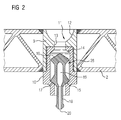
- FIG. 2 shows a further embodiment of the Entskyssanssstopfens, in which the outer housing 1 is formed in two parts.
- a sleeve 9 Perpendicular to the bottom plate 2 of the rail vehicle, a sleeve 9 is provided, in which from the bottom of the bottom plate 2 of a base body 10 is screwed.
- the base body 10 and the sleeve 9 welded into the base plate 2 adjoin one another and together form an inner bore 11.
- the inner bore 11 is first formed trough-shaped, followed by a longitudinal section with a fixed diameter connects in the direction of the underside of the bottom plate 2.
- the main body 10 At the lower end of the fixed diameter section 13, the main body 10 abuts against abutment surfaces of the sleeve 9, at which transition the inner bore 11 is continuously continued.
- an upper sealing portion 14 which is conical.
- the base body 10 at its outwardly directed end to a lower sealing portion 15, which is also conical.
- the inner bore 11 has a constant diameter and in this area a buoyant body 26 is guided, which is generally elongate and at its upper and lower ends each having a conical shape, so that the conditions for a seal against the base body 10 is made possible at its end facing the sleeve 9 as well as at its outwardly directed end.
- the buoyant body 26 At its outwardly directed end 17, the buoyant body 26 exhibits an axial extension 18 which is not involved in its buoyancy and which protrudes from the inner bore 11 for mounting the buoyant body 26 in the base body 10.
- the operation of the buoyant body 26 is similar to the embodiment as a ball or hollow sphere, as they are based on FIG. 1 has been explained.
- the buoyant body 26 comes to the upper sealing portion 14 to the system, so that a seal of the bottom plate 2 is achieved. If no liquid is to be removed, the buoyant body 26 rests in its lower end position in the region of the sealing section 15, which likewise results in a sealing of the base plate 2.
- FIG. 3 The shape of the buoyant body is more detailed. Between the two ends 16, 17 of the buoyant body 26 tapers so that it is cylindrical in a central region between the ends 16, 17 and has a constant diameter. To increase its buoyancy, the buoyant body 26 is provided with an internal cavity 19 which communicates with the exterior via an opening 20 at the end of the axial extension 18.
- Zentriernasen 21 For centering the buoyant body 26 over the length of the inner bore 11 between the two sealing portions 14, 15 are used Zentriernasen 21, which are more in detail in the sectional view of FIG. 4 are recognizable. In the tangential direction of the buoyancy body 26 is sufficient clearance between the individual centering 21, so that a drainage of the buoyant body 15 is made possible.
- FIG. 5 illustrated embodiment of a drain plug agrees in essential elements to those who, on the basis of FIG. 2 was explained.
- the base body 25 extends in comparison to the exemplary embodiment FIG. 2 continue towards the top of the bottom plate 2.
- FIG. 5 shows the buoyancy body 26 in the lower end position, in which he causes a seal in the lower sealing portion due to its own weight.
- FIG. 6 the upper end position for the buoyant body 26 emerges.
- FIG. 7 illustrates how the drain plug is mountable.
- the sleeve 24 is inserted by means of welding in the bottom plate 2.
- the main body 25 is screwed with already arranged therein buoyancy body 26 from below into the sleeve 24.
- buoyancy body 26 is already arranged therein buoyancy body 26 from below into the sleeve 24.
- other fixation possibilities for the main body 25 relative to the sleeve 24 are conceivable.
- FIG. 8 shows the combination of the buoyancy body 26 and the main body 25 immediately before insertion of the buoyant body 26 in the main body 25th
Abstract
Die Erfindung betrifft ein Entwässerungsstopfen für einen Boden eines Schienenfahrzeugs, wobei der Entwässerungsstopfen ein Außengehäuse (1) aufweist, das in eine Öffnung im Boden des Schienenfahrzeugs einsetzbar ist und eine Innenbohrung (3) aufweist, in der ein Auftriebskörper (7, 26) zwischen zwei Dichtabschnitten (5, 6; 15, 16) der Innenbohrung (3) mit verringertem Durchmesser derart geführt ist, dass der Auftriebskörper (7, 26) in einer oberen Endstellung und in einer unteren Endstellung jeweils mit dem Außengehäuse (1) derart zur Anlage gelangt, dass der Boden nach außen hin gegenüber Druckbeaufschlagungen abgeschlossen ist, während der Auftriebskörper (7, 17) in einer Zwischenstellung zwischen der oberen und der unteren Endstellung einen Wasserabfluss durch die Innenbohrung (3) hindurch zulässt.The invention relates to a drainage plug for a floor of a rail vehicle, wherein the drainage plug has an outer housing (1) which is insertable into an opening in the floor of the rail vehicle and an inner bore (3), in which a buoyant body (7, 26) between two Sealing sections (5, 6, 15, 16) of the inner bore (3) with a reduced diameter is guided such that the buoyant body (7, 26) in an upper end position and in a lower end position in each case with the outer housing (1) comes into abutment in that the floor is closed towards the outside towards pressurization, while the buoyant body (7, 17) permits water to drain through the internal bore (3) in an intermediate position between the upper and lower end positions.
Description
Die Erfindung bezieht sich auf einen Entwässerungsstopfen für einen Boden eines Schienenfahrzeugs.The invention relates to a drainage plug for a floor of a rail vehicle.
Insbesondere bei Schienenfahrzeugen ist es erforderlich, eine Möglichkeit zu schaffen, gerade bodennahe Bereiche des Wagenkastens kontinuierlich zu entwässern. Dabei ist zu berücksichtigen, dass eine Dichtigkeit des Wagenkastens sicherzustellen ist. Dies ist insbesondere im Hochgeschwindigkeitsverkehr (HGV) von besonderer Bedeutung.In particular, in rail vehicles, it is necessary to provide a way to dehydrate just near the ground areas of the car body continuously. It should be noted that a tightness of the car body is to ensure. This is of particular importance in high-speed traffic (HGV).
Zu diesem Zweck ist es bekannt, im bodennahen Bereich eines Wagenkastens eingeschweißte Hülsen oder Rohre vorzusehen, die mittels eines Entwässerungsstopfens druckdicht verschlossen werden. Sofern sich Flüssigkeit im bodennahen Bereich durch beispielsweise Kondensatbildung oder Eindringung von Reinigungsflüssigkeiten durch Undichtigkeiten eines Fußbodens sammelt, kann diese nicht ungehindert ablaufen, da der typischer Weise eingeschraubte Entwässerungsstopfen als Barriere wirkt und somit ein freies Abfließen von Flüssigkeiten unterbindet. Zum Ermöglichen einer Entwässerung ist es erforderlich, den Entwässerungsstopfen periodisch zu öffnen und damit angefallene Flüssigkeit abzuführen. Dies zieht jedoch einen erhöhten Wartungsaufwand nach sich. Zusätzlich besteht die Gefahr, dass vom Wartungspersonal vergessen wird, nach einer Entwässerung den Entwässerungsstopfen wieder anzuschrauben. Eine solche Vorgehensweise ist z.B. von dem Fahrzeug "Velaro RUS", Markteinführung 2009, bekannt. Dies ermöglicht zwar eine kontinuierliche Entwässerung, bewirkt aber gleichzeitig den Verlust einer Druckdichtigkeit des Schienenfahrzeugs.For this purpose, it is known to provide welded sleeves or tubes in the vicinity of the floor of a car body, which are pressure-tightly sealed by means of a dewatering plug. If liquid collects in the ground-near area by, for example, condensation or penetration of cleaning fluids through leaks in a floor, this can not proceed unhindered, since the typically screwed drainage plug acts as a barrier and thus prevents free flow of liquids. To allow drainage, it is necessary to periodically open the drain plug and drain any accumulated liquid. However, this entails an increased maintenance costs. In addition, there is a risk that the maintenance personnel will forget to screw back the drain plug after draining. Such an approach is e.g. from the vehicle "Velaro RUS", market launch in 2009, known. Although this allows a continuous drainage, but at the same time causes the loss of pressure-tightness of the rail vehicle.
Ausgehend hiervon liegt der Erfindung die Aufgabe zugrunde, den eingangs genannten Entwässerungsstopfen derart weiterzuentwickeln, dass mit vermindertem Wartungsaufwand, sowohl eine Entwässerung des bodennahen Bereichs des Schienenfahrzeugs, als auch eine Druckdichtigkeit des Fahrzeugs verwirklicht werden kann.Proceeding from this, the present invention seeks to further develop the above-mentioned dewatering plug such that with reduced maintenance, both a Drainage of the ground-level region of the rail vehicle, as well as a pressure tightness of the vehicle can be realized.
Diese Aufgabe wird bei dem Entwässerungsstopfen dadurch gelöst, dass der Entwässerungsstopfen ein Außengehäuse aufweist, das in eine Öffnung im Boden des Schienenfahrzeugs einsetzbar ist und eine Innenbohrung aufweist, in der ein Auftriebskörper zwischen zwei Dichtabschnitten der Innenbohrung mit verringertem Durchmesser derart geführt ist, dass der Auftriebskörper in einer oberen Endstellung und in einer unteren Endstellung jeweils mit dem Außengehäuse derart zur Anlage gelangt, dass der Boden nach außen hin gegenüber Druckbeaufschlagungen abgeschlossen ist, während der Auftriebskörper in einer Zwischenstellung zwischen der oberen und der unteren Endstellung einen Wasserabfluss durch die Innenbohrung hindurch zulässt.This object is achieved in the dewatering plug in that the drainage plug has an outer housing which is insertable into an opening in the bottom of the rail vehicle and having an inner bore in which a buoyant body between two sealing portions of the inner bore of reduced diameter is guided such that the buoyant body in an upper end position and in a lower end position in each case comes to rest with the outer housing such that the bottom is closed to the outside against pressurization, while the buoyant body in an intermediate position between the upper and lower end position allows a water drain through the inner bore therethrough.
Bei einem solchen Entwässerungsstopfen, eingebaut in den Boden eines Schienenfahrzeugs, bewegt sich der Auftriebskörper typischer Weise in vertikaler Richtung zwischen der oberen und der unteren Endstellung, bei denen jeweils eine Abdichtung nach außen vorliegt. Sofern keine zu entwässernde Flüssigkeit vorhanden ist, ruht der Auftriebskörper aufgrund seiner Schwerkraft in der unteren Endstellung und sorgt dort für eine Druckdichtigkeit des Schienenfahrzeugs. In dem unwahrscheinlichen Fall, dass der Außendruck derart bemessen ist, dass der Auftriebskörper nach oben in Richtung auf die oberen Endstellung gedrückt wird, ist das Schienenfahrzeug nur über einen Zeitraum nicht druckdicht, den der Auftriebskörper zum Zurücklegen des Weges von der unteren in die obere Endstellung benötigt.In such a drainage plug, installed in the floor of a rail vehicle, the buoyancy body typically moves in the vertical direction between the upper and lower end position, each having a seal to the outside. If there is no liquid to be dehydrated, the buoyancy body rests in the lower end position due to its gravitational force and ensures pressure-tightness of the rail vehicle there. In the unlikely event that the external pressure is such that the buoyant body is pushed upwards towards the upper end position, the rail vehicle is not pressure-tight for a period of time until the buoyancy body traverses the path from the lower to the upper end position needed.
Sofern die Innenbohrung mit Flüssigkeit beaufschlagt wird, die zu entwässern ist, verlässt der Auftriebskörper die untere Endstellung und öffnet ähnlich einem Ventil die nach außen weisende Seite der Innenbohrung, so dass die Flüssigkeit ablaufen kann. Nach vollständiger Entwässerung nimmt der Auftriebskörper seine ursprüngliche Position in der unteren Endstellung wieder ein, so dass Druckdichtigkeit gegeben ist.If the inner bore is charged with liquid that is to be dewatered, the buoyant body leaves the lower end position and opens like a valve, the outwardly facing side of the inner bore, so that the liquid can drain. After complete drainage, the buoyant body decreases its original position in the lower end position again, so that pressure tightness is given.
Das Außengehäuse des Entwässerungsstopfens kann auswärts des oberen Dichtabschnitts kegelförmig erweitert sein. Dies hat den Vorteil, dass der obere Teil des Außengehäuses im eingebauten Zustand eine Art Mulde ausbildet, in die bodennahe Flüssigkeit gelangen kann.The outer casing of the dewatering plug may be tapered outwardly of the upper sealing portion. This has the advantage that the upper part of the outer housing in the installed state forms a kind of trough, can get into the ground-level liquid.
Der Auftriebskörper kann als Kugel oder Hohlkugel ausgebildet sein, deren Durchmesser kleiner als der Durchmesser der Innenbohrung des Außengehäuses zwischen den zwei Dichtabschnitten ist. Dabei ist die Differenz zwischen dem Durchmesser der Innenbohrung und dem Durchmesser der Kugel so zu bemessen, dass auch mit abzuführenden Schmutzpartikeln an der Kugel vorbei durch die Innenbohrung nach außen gelangen können.The buoyant body may be formed as a ball or hollow sphere whose diameter is smaller than the diameter of the inner bore of the outer housing between the two sealing portions. In this case, the difference between the diameter of the inner bore and the diameter of the ball is to be dimensioned so that even with discharged dirt particles on the ball can pass through the inner bore to the outside.
Alternativ zu der Kugelform kann der Auftriebskörper auch allgemein zylindrisch und an seinen Enden kegelstumpfförmig ausgebildet sein, wobei sein Durchmesser entfernt von den Enden kleiner als der Durchmesser der Innenbohrung des Außengehäuses zwischen den zwei Dichtabschnitten ist. Zum Zusammenwirken des Auftriebskörpers mit der Innenbohrung ist es günstig, dass die Dichtabschnitte der Innenbohrung mit verringertem Durchmesser an die Kegelstumpfform der Enden des Auftriebskörpers angepasst sind, so dass Druckdichtigkeit herstellbar ist.As an alternative to the spherical shape, the buoyant body can also be generally cylindrical and frusto-conical at its ends, its diameter away from the ends being smaller than the diameter of the inner bore of the outer housing between the two sealing sections. For cooperation of the buoyant body with the inner bore, it is favorable that the sealing portions of the inner bore are adapted with reduced diameter to the truncated cone shape of the ends of the buoyant body, so that pressure tightness can be produced.
Der Auftriebskörper kann Zentriernasen zur Führung des Auftriebskörpers in der Innenbohrung des Außengehäuses aufweisen. Dies bewirkt eine kontrollierte Bewegung des Auftriebskörpers zwischen den zwei Dichtabschnitten der Innenbohrung.The buoyancy body may have centering lugs for guiding the buoyant body in the inner bore of the outer housing . This causes a controlled movement of the buoyant body between the two sealing portions of the inner bore.
Der Auftriebskörper kann eine aus dem Außengehäuse herausragende axiale Verlängerung zu seiner Handhabung bei einer Montage aufweisen. Diese Verlängerung schließt sich dann an eines der Enden des eigentlichen Auftriebskörpers an.The buoyant body may have an axial extension protruding from the outer housing for handling during assembly. This extension then joins one of the ends of the actual buoyant body.
Das Außengehäuse kann einteilig ausgebildet und in die Öffnung im Boden des Schienenfahrzeugs einklebbar sein. Alternativ dazu kann das Außengehäuse auch zweiteilig ausgebildet sein und einen Grundkörper, in dem der Auftriebskörper geführt ist, sowie eine in die Öffnung im Boden des Schienenfahrzeugs einschweißbare Hülse aufweisen, in der der Grundkörper axial eingesetzt und fixiert ist. Insbesondere kann der Grundkörper in die Hülse einschraubbar sein. Dies hat den Vorteil, dass der Auftriebskörper frei in die Innenbohrung des Grundkörpers einlegbar ist und durch Ausschrauben des Grundkörpers aus der Hülse ohne Zusatzwerkzeug wieder entnommen werden kann. Auch kann die Innenbohrung im Bereich des Grundkörpers bei Bedarf gereinigt werden. Zudem kann bei Beschädigung des Auftriebskörpers dieser in einfacher Weise ausgetauscht werden.The outer housing may be integrally formed and be glued into the opening in the bottom of the rail vehicle. Alternatively, the outer housing may also be formed in two parts and have a base body, in which the buoyancy body is guided, and a weldable into the opening in the bottom of the rail vehicle sleeve in which the base body is axially inserted and fixed. In particular, the main body can be screwed into the sleeve. This has the advantage that the buoyancy body is freely inserted into the inner bore of the body and can be removed by unscrewing the body from the sleeve without additional tool again. Also, the inner bore in the region of the body can be cleaned if necessary. In addition, it can be easily replaced if the buoyant body is damaged.
Die zwei Dichtabschnitte der Innenbohrung können im Bereich des Grundkörpers angeordnet sein. In diesem Fall ist bei der zweiteiligen Ausführung des Außengehäuses die Hülse an einer Abdichtung eines Fahrzeuginnenraums gegenüber der Umgebung des Fahrzeugs nicht beteiligt. Alternativ dazu kann einer der zwei Dichtabschnitte der Innenbohrung im Bereich des Grundkörpers und der andere im Bereich der Hülse angeordnet sein. Der Dichtabschnitt im Bereich der Hülse kann dann beispielsweise als Absatz ausgebildet sein, mit dem ein zugeordnetes Ende des Auftriebskörpers für Dichtzwecke zusammenwirkt.The two sealing portions of the inner bore may be arranged in the region of the base body. In this case, in the two-piece embodiment of the outer casing, the sleeve is not involved in sealing a vehicle interior from the environment of the vehicle. Alternatively, one of the two sealing portions of the inner bore in the region of the base body and the other may be arranged in the region of the sleeve. The sealing portion in the region of the sleeve can then be designed, for example, as a shoulder, with which an associated end of the buoyant body cooperates for sealing purposes.
Zur Erhöhung des Auftriebs des Auftriebskörpers kann es von Vorteil sein, wenn er einen inneren Hohlraum aufweist. Dies kann insbesondere dann erforderlich werden, das Material des Auftriebskörpers eine eher hohe Dichte aufweist.To increase the buoyancy of the buoyant body, it may be advantageous if it has an inner cavity. This may be necessary in particular when the material of the buoyant body has a rather high density.
Der Auftriebskörper kann aus elastischem Material hergestellt sein. Diese Variante für die Ausführung des Auftriebskörpers ist insbesondere vorteilhaft, wenn beide Dichtabschnitte im Bereich des Grundkörpers angeordnet sind. Ausführungsbeispiele der Erfindung werden nachfolgend unter Bezugnahme auf die Zeichnungen noch näher erläutert, wobei funktionsgleiche Komponenten mit denselben Bezugszeichen bezeichnet sind. Es zeigen:
- Figur 1
- eine Querschnittsansicht eines Entwässerungsstopfens nach einer ersten Ausführungsform im eingebauten Zustand,
Figur 2- eine Querschnittsansicht eines Entwässerungsstopfens nach einer zweiten Ausführungsform in eingebautem Zustand,
- Figur 3
- eine Längsschnittansicht eines Auftriebskörpers zum Einsatz bei den Entwässerungsstopfen nach
Figur 2 Figur 4- eine Querschnittsansicht des Auftriebskörpers nach
Figur 3 entlang einer Linie IV-IV, - Figur 5
- eine perspektivische Schnittansicht eines Entwässerungsstopfens nach einer dritten Ausführungsform in eingebautem Zustand mit einem Auftriebskörper in einer unteren Endstellung,
Figur 6- eine perspektivische Schnittansicht des Entwässerungsstopfens nach
Figur 5 in eingebautem Zustand mit dem Auftriebskörper in einer oberen Endstellung, - Figur 7
- eine perspektivische, auseinandergezogene Ansicht des Entwässerungsstopfens nach den
Figuren 5 und6 in Kombination mit dem Boden eines Schienenfahrzeugs und Figur 8- eine auseinandergezogene Ansicht von Komponenten des Entwässerungsstopfens nach den
Figuren 5 und6 .
- FIG. 1
- a cross-sectional view of a drainage plug according to a first embodiment in the installed state,
- FIG. 2
- a cross-sectional view of a drainage plug according to a second embodiment in the installed state,
- FIG. 3
- a longitudinal sectional view of a buoyancy body for use in the drainage plug after
FIG. 2 . - FIG. 4
- a cross-sectional view of the buoyancy body after
FIG. 3 along a line IV-IV, - FIG. 5
- a sectional perspective view of a drainage plug according to a third embodiment in the installed state with a buoyant body in a lower end position,
- FIG. 6
- a perspective sectional view of the drainage plug after
FIG. 5 in the installed state with the buoyant body in an upper end position, - FIG. 7
- a perspective, exploded view of the drain plug after the
Figures 5 and6 in combination with the floor of a rail vehicle and - FIG. 8
- an exploded view of components of the drain plug after the
Figures 5 and6 ,
Die in
Innerhalb der Innenbohrung 3 ist eine frei bewegliche und als Auftriebskörper 7 wirkende Kugel angeordnet, deren Durchmesser geringer ist als der Durchmesser der Innenbohrung 3 im Bereich zwischen den beiden Dichtabschnitten. Gleichzeitig ist der Durchmesser der Kugel so gewählt, dass er die Innenbohrung 3 sowohl in seiner oberen Endstellung im Bereich des oberen Dichtabschnitts 5 als auch in seiner unteren Endstellung im Bereich des unteren Dichtabschnitts 6 möglichst druckdicht verschließt.Within the inner bore 3 a freely movable and acting as a buoyant body 7 ball is arranged, whose diameter is smaller than the diameter of the inner bore 3 in the region between the two sealing portions. At the same time, the diameter of the ball is selected so that it closes the inner bore 3 in its upper end position in the region of the upper sealing portion 5 and in its lower end position in the region of the
Wenn nun abzuführendes Wasser von der Oberseite der Bodenplatte 2 aus in die Innenbohrung 3 gelangt, wird der Auftriebskörper 7 von seiner unteren Endstellung aus, die er aufgrund seiner Schwerkraft einnimmt, nach oben bewegt und erreicht bei weiter nachfließendem Wasser den oberen Dichtabschnitt 5. Dann kann kein weiteres Wasser mehr von der Oberseite der Bodenplatte 2 aus nachfließen und der Entwässerungsstopfen verschließt die Innenbohrung 3.Now, if water to be discharged from the top of the
Als Materialien für den Auftriebskörper 7 kommen Gummi, Schaumstoff o.ä. in Frage. Diese Materialien gewährleisten, dass die Kugel eine geeignete Druckabdichtung im Bereich der Dichtabschnitte 5, 6 bewirkt.As materials for the buoyant body 7 come rubber, foam o.ä. in question. These materials ensure that the ball causes a suitable pressure seal in the region of the sealing
Im Bereich des oberen Dichtabschnitts 5 können zusätzlich Entwässerungsnuten 8 vorgesehen sein, wenn eine optimale Druckdichtigkeit im Bereich des oberen Dichtabschnitts 5 nicht erforderlich ist, jedoch eine freie Dauerentwässerung bei hohem Wasseranfall realisiert werden soll.In the area of the upper sealing section 5,
Am oberen Ende des Grundkörpers 10 findet sich ein oberer Dichtabschnitt 14, der kegelförmig ausgebildet ist. Demgegenüber weist der Grundkörper 10 an seinem nach außen gerichteten Ende einen unteren Dichtabschnitt 15 auf, der ebenfalls kegelförmig ausgebildet ist. Zwischen den beiden Dichtabschnitten 14, 15 hat die Innenbohrung 11 einen konstanten Durchmesser und in diesem Bereich wird ein Auftriebskörper 26 geführt, der allgemein länglich ausgebildet ist und an seinem oberen und seinem unteren Ende jeweils eine Kegelform aufweist, so dass die Voraussetzungen für eine Abdichtung gegenüber dem Grundkörper 10 an seinem der Hülse 9 zugewandten Ende als auch an seinem nach außen gerichteten Ende ermöglicht ist.At the upper end of the
An seinem nach außen gerichteten Ende 17 zeigt der Auftriebskörper 26 eine an seinem Auftrieb nicht beteiligte axiale Verlängerung 18, die aus der Innenbohrung 11 für eine Montage des Auftriebskörpers 26 in dem Grundkörper 10 herausragt.At its outwardly directed
Die Funktionsweise des Auftriebskörpers 26 ist ähnlich der Ausführungsform als Kugel oder Hohlkugel, wie sie anhand von
Aus
Zur Zentrierung des Auftriebskörpers 26 über den Längenabschnitt der Innenbohrung 11 zwischen den beiden Dichtabschnitten 14, 15 dienen Zentriernasen 21, die mehr im Detail in der Schnittdarstellung von
Die Anhand von
Claims (12)
dadurch gekennzeichnet, dass
der Entwässerungsstopfen ein Außengehäuse (1) aufweist, das in eine Öffnung im Boden des Schienenfahrzeugs einsetzbar ist und eine Innenbohrung (3) aufweist, in der ein Auftriebskörper (7, 26) zwischen zwei Dichtabschnitten (5, 6; 14, 15) der Innenbohrung (3) mit verringertem Durchmesser derart geführt ist, dass der Auftriebskörper (7, 26) in einer oberen Endstellung und in einer unteren Endstellung jeweils mit dem Außengehäuse (1) derart zur Anlage gelangt, dass der Boden nach außen hin gegenüber Druckbeaufschlagungen abgeschlossen ist, während der Auftriebskörper (7, 26) in einer Zwischenstellung zwischen der oberen und der unteren Endstellung einen Wasserabfluss durch die Innenbohrung (3) hindurch zulässt.Drainage plug for a floor of a railway vehicle,
characterized in that
the drainage plug comprises an outer housing (1) which is insertable into an opening in the floor of the rail vehicle and has an inner bore (3) in which a buoyancy body (7, 26) between two sealing portions (5, 6; 14, 15) of the inner bore (3) is guided with reduced diameter such that the buoyant body (7, 26) in an upper end position and in a lower end position in each case with the outer housing (1) comes to bear in such a way that the bottom is closed to the outside against pressurization, while the buoyant body (7, 26) in an intermediate position between the upper and the lower end position allows a water drainage through the inner bore (3) therethrough.
dadurch gekennzeichnet, dass
das Außengehäuse (1) auswärts des oberen Dichtabschnitts kegelförmig erweitert ist.Drainage plug according to claim 1,
characterized in that
the outer housing (1) outwardly of the upper sealing portion is widened conically.
dadurch gekennzeichnet, dass
der Auftriebskörper (7) als Kugel ausgebildet ist, deren Durchmesser kleiner als der Durchmesser der Innenbohrung (3) des Außengehäuses (1) zwischen den zwei Dichtabschnitten (5, 6) ist.Drainage plug according to claim 1 or 2,
characterized in that
the buoyancy body (7) is formed as a ball whose diameter is smaller than the diameter of the inner bore (3) of the outer housing (1) between the two sealing portions (5, 6).
dadurch gekennzeichnet, dass
der Auftriebskörper (26) allgemein zylindrisch und an seinen Enden (16, 17) kegel- oder kegelstumpfförmig ausgebildet ist, wobei sein Durchmesser entfernt von den Enden kleiner als der Durchmesser der Innenbohrung (3) des Außengehäuses (1) zwischen den zwei Dichtabschnitten (14, 15, 22, 23) ist.Drainage plug according to claim 1 or 2,
characterized in that
the buoyancy body (26) is generally cylindrical and conical or frusto-conical at its ends (16, 17), its diameter being smaller than the diameter of the inner bore (3) of the outer housing (1) between the two sealing portions (14th) , 15, 22, 23).
dadurch gekennzeichnet, dass
der Auftriebskörper (26) Zentriernasen (21) zur Führung des Auftriebskörpers (26) in der Innenbohrung (3) des Außengehäuses (1) aufweist.Drainage plug according to claim 4,
characterized in that
the buoyancy body (26) has centering lugs (21) for guiding the buoyant body (26) in the inner bore (3) of the outer housing (1).
dadurch gekennzeichnet, dass
der Auftriebskörper (26) eine aus dem Außengehäuse (1) herausragende axiale Verlängerung (18) zu seiner Handhabung bei einer Montage aufweist.Drainage plug according to one of claims 4 or 5,
characterized in that
the buoyancy body (26) has an axial extension (18) projecting out of the outer housing (1) for handling during assembly.
dadurch gekennzeichnet, dass
das Außengehäuse (1) einteilig ausgebildet und in die Öffnung im Boden des Schienenfahrzeugs einklebbar ist.Drainage plug according to one of claims 1 to 6,
characterized in that
the outer housing (1) is formed in one piece and can be glued into the opening in the bottom of the rail vehicle.
dadurch gekennzeichnet, dass
das Außengehäuse (1) zweiteilig ausgebildet ist und einen Grundkörper (10, 25), in dem der Auftriebskörper (26) geführt ist, sowie eine in die Öffnung im Boden des Schienenfahrzeugs einschweißbare Hülse (9, 24) aufweist, in die der Grundkörper (10, 25) axial eingesetzt ist.Drainage plug according to one of claims 1 to 6,
characterized in that
the outer housing (1) is formed in two parts and has a main body (10, 25) in which the buoyancy body (26) is guided, and a sleeve (9, 24) which can be welded into the opening in the floor of the rail vehicle and into which the main body (10) 10, 25) is inserted axially.
dadurch gekennzeichnet, dass
die zwei Dichtabschnitte (14, 15) der Innenbohrung (3) im Bereich des Grundkörpers (10) angeordnet sind.Drainage plug according to claim 8,
characterized in that
the two sealing portions (14, 15) of the inner bore (3) in the region of the base body (10) are arranged.
dadurch gekennzeichnet, dass
einer der zwei Dichtabschnitte (22, 23) der Innenbohrung (3) im Bereich des Grundkörpers (25) und der andere im Bereich der Hülse (24) angeordnet sind.Drainage plug according to claim 8,
characterized in that
one of the two sealing portions (22, 23) of the inner bore (3) in the region of the base body (25) and the other in the region of the sleeve (24) are arranged.
dadurch gekennzeichnet, dass
der Auftriebskörper (26) einen inneren Hohlraum (19) aufweist.Drainage plug according to one of claims 1 to 10,
characterized in that
the buoyancy body (26) has an internal cavity (19).
dadurch gekennzeichnet, dass
der Auftriebskörper (26) aus elastischem Material hergestellt ist.Drainage plug according to one of claims 1 to 11,
characterized in that
the buoyancy body (26) is made of elastic material.
Applications Claiming Priority (1)
| Application Number | Priority Date | Filing Date | Title |
|---|---|---|---|
| DE102013206402.0A DE102013206402A1 (en) | 2013-04-11 | 2013-04-11 | Drainage plug for a rail vehicle floor |
Publications (1)
| Publication Number | Publication Date |
|---|---|
| EP2789520A1 true EP2789520A1 (en) | 2014-10-15 |
Family
ID=50396944
Family Applications (1)
| Application Number | Title | Priority Date | Filing Date |
|---|---|---|---|
| EP20140162318 Withdrawn EP2789520A1 (en) | 2013-04-11 | 2014-03-28 | Drainage plug for a rail vehicle floor |
Country Status (2)
| Country | Link |
|---|---|
| EP (1) | EP2789520A1 (en) |
| DE (1) | DE102013206402A1 (en) |
Cited By (4)
| Publication number | Priority date | Publication date | Assignee | Title |
|---|---|---|---|---|
| EP3051192A1 (en) * | 2015-01-21 | 2016-08-03 | Siemens Aktiengesellschaft | Fluid valve, in particular for vehicles |
| CN106286906A (en) * | 2015-05-22 | 2017-01-04 | 舍弗勒技术股份两合公司 | A kind of floating check valve and electric driver |
| CN109131404A (en) * | 2018-09-28 | 2019-01-04 | 镇江市博德电气设备有限公司 | A kind of electric heating draining guide tube of ease of assembly draining |
| CN110104005A (en) * | 2019-05-10 | 2019-08-09 | 中车资阳机车有限公司 | A kind of outer corridor locomotive rain-proof raised floor construction |
Citations (10)
| Publication number | Priority date | Publication date | Assignee | Title |
|---|---|---|---|---|
| DE8603781U1 (en) * | 1986-02-13 | 1986-04-03 | Deutsche Bundesbahn, vertreten durch das Bundesbahn-Zentralamt Minden (Westf), 4950 Minden | Differential pressure valve |
| DE3732565A1 (en) * | 1987-09-26 | 1989-04-06 | Rainer Schmieg | Nonreturn valve |
| US4981154A (en) * | 1990-01-30 | 1991-01-01 | Hollister, Inc. | Fluid flow control device |
| US5662138A (en) * | 1996-06-12 | 1997-09-02 | Wang; Wen-Hsing | Drop head structure |
| DE19649864A1 (en) * | 1996-12-02 | 1998-06-04 | Graaff Vertriebs Gmbh | Automatic drainage device for freight containers or other cargo-receiving rooms |
| WO2001000477A1 (en) * | 1999-06-25 | 2001-01-04 | Collins & Aikman Products Co. | Insertable vehicle floor drain |
| US20030196567A1 (en) * | 2001-02-09 | 2003-10-23 | Trn Business Trust | Pultruded panel |
| US20060076054A1 (en) * | 2004-10-07 | 2006-04-13 | Jen-Pen Chang | Liquid draining valve structure |
| EP1683742A1 (en) * | 2005-01-22 | 2006-07-26 | Waggonbau Elze GmbH & Co. Besitz KG | Valve for dewatering of freight containers |
| EP1832492A2 (en) * | 2006-03-09 | 2007-09-12 | Siemens Aktiengesellschaft | Rail vehicle equipped with a drainage system for the door area |
Family Cites Families (1)
| Publication number | Priority date | Publication date | Assignee | Title |
|---|---|---|---|---|
| DE1775614A1 (en) * | 1967-09-25 | 1971-08-12 | Alfredo Brusegan | Device with safety valve for automatic interruption of the suction of a liquid |
-
2013
- 2013-04-11 DE DE102013206402.0A patent/DE102013206402A1/en not_active Ceased
-
2014
- 2014-03-28 EP EP20140162318 patent/EP2789520A1/en not_active Withdrawn
Patent Citations (10)
| Publication number | Priority date | Publication date | Assignee | Title |
|---|---|---|---|---|
| DE8603781U1 (en) * | 1986-02-13 | 1986-04-03 | Deutsche Bundesbahn, vertreten durch das Bundesbahn-Zentralamt Minden (Westf), 4950 Minden | Differential pressure valve |
| DE3732565A1 (en) * | 1987-09-26 | 1989-04-06 | Rainer Schmieg | Nonreturn valve |
| US4981154A (en) * | 1990-01-30 | 1991-01-01 | Hollister, Inc. | Fluid flow control device |
| US5662138A (en) * | 1996-06-12 | 1997-09-02 | Wang; Wen-Hsing | Drop head structure |
| DE19649864A1 (en) * | 1996-12-02 | 1998-06-04 | Graaff Vertriebs Gmbh | Automatic drainage device for freight containers or other cargo-receiving rooms |
| WO2001000477A1 (en) * | 1999-06-25 | 2001-01-04 | Collins & Aikman Products Co. | Insertable vehicle floor drain |
| US20030196567A1 (en) * | 2001-02-09 | 2003-10-23 | Trn Business Trust | Pultruded panel |
| US20060076054A1 (en) * | 2004-10-07 | 2006-04-13 | Jen-Pen Chang | Liquid draining valve structure |
| EP1683742A1 (en) * | 2005-01-22 | 2006-07-26 | Waggonbau Elze GmbH & Co. Besitz KG | Valve for dewatering of freight containers |
| EP1832492A2 (en) * | 2006-03-09 | 2007-09-12 | Siemens Aktiengesellschaft | Rail vehicle equipped with a drainage system for the door area |
Cited By (6)
| Publication number | Priority date | Publication date | Assignee | Title |
|---|---|---|---|---|
| EP3051192A1 (en) * | 2015-01-21 | 2016-08-03 | Siemens Aktiengesellschaft | Fluid valve, in particular for vehicles |
| CN106286906A (en) * | 2015-05-22 | 2017-01-04 | 舍弗勒技术股份两合公司 | A kind of floating check valve and electric driver |
| CN106286906B (en) * | 2015-05-22 | 2019-12-10 | 舍弗勒技术股份两合公司 | Floating one-way valve and electric driving device |
| CN109131404A (en) * | 2018-09-28 | 2019-01-04 | 镇江市博德电气设备有限公司 | A kind of electric heating draining guide tube of ease of assembly draining |
| CN109131404B (en) * | 2018-09-28 | 2024-02-27 | 镇江市博德电气设备有限公司 | Electric heating drainage guide cylinder convenient for assembly drainage |
| CN110104005A (en) * | 2019-05-10 | 2019-08-09 | 中车资阳机车有限公司 | A kind of outer corridor locomotive rain-proof raised floor construction |
Also Published As
| Publication number | Publication date |
|---|---|
| DE102013206402A1 (en) | 2014-10-16 |
Similar Documents
| Publication | Publication Date | Title |
|---|---|---|
| DE2431516C3 (en) | Device for dispensing fluids | |
| EP3213803B1 (en) | Filter assembly | |
| DE202005016046U1 (en) | Sanitary installation part | |
| DE3242945A1 (en) | VALVE ARRANGEMENT | |
| DE69921003T2 (en) | Sink drain arrangement | |
| DE202010011973U1 (en) | Oil drain device | |
| EP2789520A1 (en) | Drainage plug for a rail vehicle floor | |
| WO2021013417A1 (en) | Filter apparatus | |
| DE2127415A1 (en) | Auxiliary controlled safety valve device, in particular for hydraulic and pneumatic systems | |
| WO2005007267A1 (en) | Oil filter arrangement and filter element | |
| EP2181275A1 (en) | Protective pipe for a piston/cylinder unit | |
| DE1963709A1 (en) | Device for preventing or reducing pressure surges in pipeline networks | |
| EP3157794A1 (en) | Rail vehicle comprising a lower base plate having a drainage device | |
| EP3095500B1 (en) | Pressure reducing filter arrangement | |
| DE202008011272U1 (en) | Drain, especially for floor-level showers | |
| EP3026185B1 (en) | Antiflooding valve | |
| EP3199715A2 (en) | Overflow for a basin, in particular rinsing basin | |
| DE202016105070U1 (en) | Backwash filter arrangement | |
| DE10207633A1 (en) | In line filtration assembly, e.g. for lubrication system of IC engine, has double filter element | |
| DE3106578A1 (en) | DOUBLE SEAT VALVE WITH LEAK CONTROL | |
| DE2637143A1 (en) | HIGH PRESSURE LIQUID LINE FITTED WITH A SHUT-OFF SYSTEM | |
| DE19850382A1 (en) | Automotive oil drain plug has reservoir outlet sealed by a drain valve at the lowest point in the reservoir | |
| DE102007017377B4 (en) | Hydrant-emptying system | |
| WO1989001879A1 (en) | Coupling piece for insertion in an opening of a container | |
| EP3469155B1 (en) | Shut-off element and hydrant with such a shut-off element |
Legal Events
| Date | Code | Title | Description |
|---|---|---|---|
| PUAI | Public reference made under article 153(3) epc to a published international application that has entered the european phase |
Free format text: ORIGINAL CODE: 0009012 |
|
| 17P | Request for examination filed |
Effective date: 20140328 |
|
| AK | Designated contracting states |
Kind code of ref document: A1 Designated state(s): AL AT BE BG CH CY CZ DE DK EE ES FI FR GB GR HR HU IE IS IT LI LT LU LV MC MK MT NL NO PL PT RO RS SE SI SK SM TR |
|
| AX | Request for extension of the european patent |
Extension state: BA ME |
|
| R17P | Request for examination filed (corrected) |
Effective date: 20150407 |
|
| RBV | Designated contracting states (corrected) |
Designated state(s): AL AT BE BG CH CY CZ DE DK EE ES FI FR GB GR HR HU IE IS IT LI LT LU LV MC MK MT NL NO PL PT RO RS SE SI SK SM TR |
|
| RAP1 | Party data changed (applicant data changed or rights of an application transferred) |
Owner name: SIEMENS AKTIENGESELLSCHAFT |
|
| RIC1 | Information provided on ipc code assigned before grant |
Ipc: F16K 24/04 20060101ALI20180531BHEP Ipc: F16K 15/04 20060101ALI20180531BHEP Ipc: F16K 31/18 20060101ALI20180531BHEP Ipc: B61D 17/10 20060101AFI20180531BHEP |
|
| GRAP | Despatch of communication of intention to grant a patent |
Free format text: ORIGINAL CODE: EPIDOSNIGR1 |
|
| INTG | Intention to grant announced |
Effective date: 20181114 |
|
| STAA | Information on the status of an ep patent application or granted ep patent |
Free format text: STATUS: THE APPLICATION IS DEEMED TO BE WITHDRAWN |
|
| 18D | Application deemed to be withdrawn |
Effective date: 20190326 |