EP2599666A1 - Structure for vehicle body front portion - Google Patents
Structure for vehicle body front portion Download PDFInfo
- Publication number
- EP2599666A1 EP2599666A1 EP10855307.4A EP10855307A EP2599666A1 EP 2599666 A1 EP2599666 A1 EP 2599666A1 EP 10855307 A EP10855307 A EP 10855307A EP 2599666 A1 EP2599666 A1 EP 2599666A1
- Authority
- EP
- European Patent Office
- Prior art keywords
- plate portion
- vehicle
- bracket
- rear direction
- bottom plate
- Prior art date
- Legal status (The legal status is an assumption and is not a legal conclusion. Google has not performed a legal analysis and makes no representation as to the accuracy of the status listed.)
- Granted
Links
Images





Classifications
-
- B—PERFORMING OPERATIONS; TRANSPORTING
- B60—VEHICLES IN GENERAL
- B60R—VEHICLES, VEHICLE FITTINGS, OR VEHICLE PARTS, NOT OTHERWISE PROVIDED FOR
- B60R21/00—Arrangements or fittings on vehicles for protecting or preventing injuries to occupants or pedestrians in case of accidents or other traffic risks
- B60R21/34—Protecting non-occupants of a vehicle, e.g. pedestrians
-
- B—PERFORMING OPERATIONS; TRANSPORTING
- B62—LAND VEHICLES FOR TRAVELLING OTHERWISE THAN ON RAILS
- B62D—MOTOR VEHICLES; TRAILERS
- B62D25/00—Superstructure or monocoque structure sub-units; Parts or details thereof not otherwise provided for
- B62D25/08—Front or rear portions
- B62D25/082—Engine compartments
- B62D25/084—Radiator supports
-
- B—PERFORMING OPERATIONS; TRANSPORTING
- B60—VEHICLES IN GENERAL
- B60R—VEHICLES, VEHICLE FITTINGS, OR VEHICLE PARTS, NOT OTHERWISE PROVIDED FOR
- B60R21/00—Arrangements or fittings on vehicles for protecting or preventing injuries to occupants or pedestrians in case of accidents or other traffic risks
- B60R21/34—Protecting non-occupants of a vehicle, e.g. pedestrians
- B60R2021/343—Protecting non-occupants of a vehicle, e.g. pedestrians using deformable body panel, bodywork or components
Definitions
- the present invention relates to a vehicle body front portion structure in which a bracket for parts mounting is fixed to a skeleton member beneath a hood front end portion.
- An object of the present invention is to obtain a vehicle body front portion structure that, when an impact is inputted to a hood front end, can absorb impact energy by a needed load even while the hood interferes with a bracket for parts mounting.
- a vehicle body front portion structure relating to a first aspect of the present invention comprises: a hood member that covers a front portion of a vehicle from an upper side; a skeleton member that has a top wall facing an upper side in a vehicle up-down direction and a front wall facing a front side in a vehicle front-rear direction, and that is long along a vehicle transverse direction, and that is disposed at a vehicle lower side with respect to a front end side, in the vehicle front-rear direction, of the hood member; a bracket for part fixing that is structured to include a ceiling plate portion at whose rear end portion in the vehicle front-rear direction is provided an upper joining portion that is fixed to the top wall, and a bottom plate portion at whose rear end portion in the vehicle front-rear direction is provided a lower joining portion that is fixed to vehicle the front wall, and a front plate portion that connects a front end side in the vehicle front-rear direction of the ceiling plate portion and a front end side in the vehicle front-rear direction of the bottom
- the bracket forms a closed cross-sectional structure by the ceiling plate portion, bottom plate portion and front plate portion thereof, and the skeleton member front wall.
- the hood deforms such that the front end portion is bent downward.
- the hood interferes with the (part mounted to the) bracket that is fixed so as to jut-out further toward the front side than the skeleton member, load of a predetermined value or more from the vehicle front upper side is inputted to the bracket.
- the fixing cancelling means functions, and the fixed state of the ceiling plate portion with the top wall of the skeleton member at the upper fixing portion is cancelled, and at least relative displacement of the ceiling plate portion toward the front with respect to the top wall becomes possible. Due thereto, the bracket translates from a closed cross-sectional structure to a state of (that is near) cantilever-support in which the lower fixing portion of the bottom plate portion is fixed to the skeleton member, and thereafter, the bracket is deformed, following the deformation of the hood front end, by a low load. Due thereto, the deformation stroke of the hood front end portion is ensured, and absorption of the collision energy of the collision body to the hood front end portion is achieved.
- the impact energy can be absorbed by the needed load even while the hood interferes with a bracket for parts mounting.
- the fixing canceling means is structured to include a fastening structure by a bolt that fixes the ceiling plate portion to the top wall by a predetermined fastening load, and a bolt relief portion that is connected, at a rear side in the vehicle front-rear direction, to a portion through which the bolt is inserted at the ceiling plate portion.
- the ceiling plate portion of the bracket is fixed firmly to the top wall of the skeleton member by the fastening structure by the bolt. Due thereto, the needed mounting rigidity is ensured. Further, a predetermined input load to the bracket, by which the fixing is cancelled, is set by the fastening load of the bolt. When fixing by the fastening structure by the bolt is cancelled, due to the bolt moving to the bolt relief portion, relative displacement of the ceiling plate portion toward the vehicle front side with respect to the top wall is permitted by a low load.
- the above-described aspect may be structured such that the lower fastening portion is fixed to the front wall of the skeleton member at a flange portion that is formed by a rear end portion, in the vehicle front-rear direction, of the bottom plate portion being folded-over downward in the vehicle up-down direction, and, at the bottom plate portion, a bead, that is long in the vehicle front-rear direction and is convex toward an upper side in the vehicle up-down direction, is formed from the front plate portion to the flange portion.
- the rigidity of the bracket itself is ensured by the bead that is formed at the bottom plate portion from the front wall to the flange portion. Due to the bracket, that has translated to the cantilevered state due to the collision of the collision body as described above, deforming such that the corner portion of the flange portion and the bottom plate portion bends, downward deformation of the hood front end portion is permitted.
- the bead that is formed at the bottom plate portion is convex upwardly, the bead is not nipped between the bottom plate portion and the flange portion that deform so as to bend as described above. Namely, due to the above-described bead, a function of improving the supporting rigidity of a part by the bracket, and a function of not impeding deformation of the bracket at the time of a collision of a collision body, can both be achieved.
- the above-described aspect may be structured such that a projecting height of the bead from the bottom plate portion at the front plate portion side is smaller than a projecting height from the bottom plate portion at the flange portion side.
- the bracket that has translated to the cantilevered state due to the collision of the collision body as described above, deforming such that the front plate portion and the bottom plate portion are bent also in directions of approaching, downward deformation of the hood front end portion is permitted.
- the projecting height of the bead from the bottom plate portion is lower at the front end side thereof than the rear end side, it is difficult for deformation of the bracket, in the above-described direction in which the front plate portion and the bottom plate portion approach, to be impeded.
- the above-described aspect may structured such that, at the ceiling plate portion, a bead, that is long in the vehicle front-rear direction and is convex toward an upper side in the vehicle up-down direction, is formed from the front plate portion to the upper joining portion.
- the rigidity of the bracket itself is ensured by the bead that is formed at the ceiling plate portion from the front wall to the flange portion. Due to the bracket, that has translated to the cantilevered state due to the collision of the collision body as described above, deforming such that the angle formed by the ceiling plate portion and the front plate portion widens, downward deformation of the hood front end portion is permitted.
- the bead that is formed at the ceiling plate portion is convex upwardly, the bead does not receive pulling between the ceiling plate portion and the front plate portion so as to resist the deformation to widen the angle as described above. Namely, a function of improving the supporting rigidity of a part by the bracket, and a function of not impeding deformation of the bracket at the time of a collision of a collision body, can both be achieved.
- the vehicle body front portion structure relating to the present invention has the excellent effect that, when an impact is inputted to a hood front end, impact energy can be absorbed by the needed load even while the hood interferes with a bracket for parts mounting.
- a vehicle body front portion structure 10 relating to an embodiment of the present invention is described on the basis of Fig. 1 through Fig. 5 .
- arrow FR that is written appropriately in the drawings indicates the front direction in the vehicle front-rear direction
- arrow UP indicates the upward direction in the vehicle up-down direction
- arrow W indicates the vehicle transverse direction, respectively.
- front-rear and up-down directions when front-rear and up-down directions are used, they indicate the front and the rear in the vehicle front-rear direction and upward and downward in the vehicle up-down direction, unless specially mentioned.
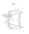
- FIG. 3 A front portion of an automobile V to which the vehicle body front portion structure 10 is applied is shown in a plan view in Fig. 3 .
- FIG. 1A A sectional view along line 1A-1A of Fig. 3 is shown in Fig. 1A .
- the automobile V has a hood 12 that serves as a hood member that closes, from the upper side, an engine room 11 that serves as an opening portion that opens toward the vehicle upper side.
- the hood 12 is structured with an outer panel 120 and an inner panel 12I being main portions thereof.
- the hood 12 is supported, at the rear end side, at the vehicle body so as to be rotatable around an axis that runs along the vehicle transverse direction, and opens and closes the engine room 11 due to this rotation with respect to the vehicle body.
- an unillustrated striker is provided so as to project-out downwardly at the front end side of the hood 12. Due to this striker being engaged with a latch at the vehicle body side, the hood 12 is locked in a state of closing the engine room 11. The automobile V travels in a state in which the engine room 11 is closed by the hood 12.
- a radiator support upper member 14 that serves as a skeleton member and that is long along the vehicle transverse direction, is disposed at the lower side in the vehicle up-down direction with respect to a front end portion 12F of the hood 12. More concretely, the radiator support upper member 14 is disposed directly in front of the mounted region of the striker at the hood 12.
- the radiator support upper member 14 is a structure that supports the upper end side of an unillustrated air-cooled heat exchanger such as a radiator or a condenser for the air conditioning unit or the like.
- the radiator support upper member 14 is structured to include a top wall 14U that faces upward and a front wall 14F that faces forward.
- the radiator support upper member 14 forms a closed cross-sectional structure that is substantially rectangular in side sectional view, by the top wall 14U and the front wall 14F and a bottom wall 14L and a rear wall 14R.
- a bracket 16 is mounted to the radiator support upper member 14 so as to project-out toward the front side in the vehicle front-rear direction with respect to the radiator support upper member 14.
- the bracket 16 holds a horn 18, that is a warning device that serves as a part, at the predetermined position with respect to the vehicle body shown in Fig. 1A and Fig. 3 .
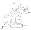
- this bracket 16 is structured to include a front plate portion 16F that faces the front wall 14F of the radiator support upper member 14, a ceiling plate portion 16U that extends toward the rear from the upper end of the front plate portion 16F, and a bottom plate portion 16L that extends toward the rear from the lower end of the front plate portion 16F.
- the front plate portion 16F, the bottom plate portion 16L and the ceiling plate portion 16U of the bracket 16 are a structure that, with the front wall 14F of the radiator support upper member 14, forms a closed cross-sectional CS that is substantially rectangular in side view.
- This bracket 16 is fixed to the radiator support upper member 14 at an upper flange 16UF, that serves as an upper fixing portion and is provided at the rear end side of the ceiling plate portion 16U, and a lower flange 16LF, that serves as a lower fixing portion and is provided at the rear end side of the bottom plate portion 16L.
- the upper flange 16UF is superposed on the top wall 14U of the radiator support upper member 14 and is fixed to the top wall 14U by fastening using bolts 20.
- the upper flange 16UF is extended rearward so as to form the same surface from the portion that structures the closed cross-section CS at the ceiling plate portion 16U, and has bolt through portions through which the bolts 20 (see Fig. 2A ) are passed.
- the bolt through portions in this embodiment are made to be slits 22 that are long in the front-rear direction and that open rearward.
- the two slits 22 are formed in parallel in the vehicle transverse direction at the upper flange 16UF that is fastened by the two bolts 20 that are disposed so as to be apart in the vehicle transverse direction.
- the ceiling plate portion 16U is fastened and fixed to the top wall 14U due to the bolts 20 being passed-through the front end portions of the slits 22 and bolt holes 14H that are formed in the top wall 14U, and being screwed-together with weld nuts 21 that are provided at the lower surface side of the top wall 14U.
- the rear side portions with respect to front end portions 22A, that are the portions that the bolts 20 are passed-through at the respective slits 22, correspond to bolt relief portions in the present invention.
- the slits 22 can also be interpreted as being openings in which rectangular slits of the same width as the diameters of the bolt holes are provided continuously at the rear of the circular bolt holes.
- the lower flange 16LF is formed as if the rear end portion of the bottom plate portion 16L were folded-over downward. This lower flange 16LF is fixed to the front wall 14F by spot welding, in a state of being superposed on the front wall 14F of the radiator support upper member 14.
- beads 24, 26, that are long in the front-rear direction are formed at the ceiling plate portion 16U, the bottom plate portion 16L, respectively.
- the bead 24 extends from the front end to the rear end (at least the upper flange 16UF that is described later) of the ceiling plate portion 16U.
- the bead 26 extends from the front end to the rear end (the lower flange 16LF that is described later) of the bottom plate portion 16L.
- the single bead 24 is disposed at the vehicle transverse direction central portion of the ceiling plate portion 16U so as to be sandwiched in the vehicle transverse direction by the pair of slits 22.
- the bead 26 is disposed at the vehicle transverse direction central portion of the bottom plate portion 16L.
- these bead 24, bead 26 are made to be convex beads that project-out upwardly from the ceiling plate portion 16U, the bottom plate portion 16L, respectively, and that open downward.
- the support rigidity of the bracket 16 needed for the horn 18 is ensured by the structure that forms the closed cross-section CS, the structure of providing the upper and lower bead 24, bead 26, and the structure of mounting to the radiator support upper member 14 by the bolts 20 and spot welding, as described above.
- the fastening load of the bracket 16 to the radiator support upper member 14 by the bolts 20 is set (managed) to a prescribed fastening load.
- This prescribed fastening load is set as a load by which the fastened and fixed state of the bracket 16 to the radiator support upper member 14 by the bolts 20 is cancelled when a load of a predetermined value or more is inputted from the front upper side toward the rear lower side to the front end side of the bracket 16 (the closed cross-section CS).
- This load is made to be a load that is sufficiently small with respect to load inputted to the bracket 16 via the hood 12 in a pedestrian femoral region protection test, and is sufficiently large with respect to load that is inputted to the bracket 16 from the horn 18 in the usual usage state of the automobile V.
- the fixing cancelling means in the present invention is structured by the setting of this fastening load and by the slits 22 (bolt relief portions).
- the bracket 16 In the vehicle body front portion structure 10 of the above-described structure, usually, a state in which the horn 18 is supported at the radiator support upper member 14 via the bracket 16 is maintained.
- the bracket 16 is fastened to the radiator support upper member 14 by the aforementioned prescribed load by the bolts 20, and the beads 24, 26 are formed at the ceiling plate portion 16U and the bottom plate portion 16L, respectively. Therefore, the bracket 16 can ensure a sufficient supporting rigidity of the horn 18. Due thereto, in the vehicle body front portion structure 10, the occurrence of chattering noise that accompanies operation of the horn 18 is prevented or effectively suppressed. Further, the durability of the bracket 16 improves due to the beads 24, 26.
- the front end portion of the hood 12 collides with the bracket 16, from the front upper side. Therefore, load of the aforementioned predetermined value or more is applied to the bracket 16 from the front upper side.
- the bracket 16 bendingly deforms such that the closed cross-section CS is crushed as shown in Fig. 1B while the fixed state of the ceiling plate portion 16U by the bolts 20 is cancelled and the rear portion of the ceiling plate portion 16U is pulled-out forward so as to slide on the top wall 14U.
- the angle formed by the ceiling plate portion 16U and the front plate portion 16F widens, the angle formed by the front plate portion 16F and the bottom plate portion 16L contracts, and the angle formed by the bottom plate portion 16L and the lower flange 16LF contracts, and deformation arises in the direction of permitting further deformation of the front end of the hood 12 (collapsing like the crushing of a box). Due thereto, even after the hood 12 contacts the bracket 16, the impact absorbing stroke of the collision body I is ensured.
- the bracket 16 when load of the predetermined value or more is applied to the bracket 16 from the front upper side, the fixed state of the ceiling plate portion 16U, by the bolts 20, of the bracket 16 is cancelled, and therefore, the above-described deformation is generated by a low load at the bracket 16. Namely, because the bracket 16 translates from the supported structure by the upper flange 16UF and the lower flange 16LF to a structure of (that can be approximated as) cantilever support by the lower flange 16LF, the bracket 16 is deformed by a low load, as compared with a structure in which this translation does not occur.
- the bead 26 of the bottom plate portion 16L projects-out upwardly, the bead is not nipped-in between the bottom plate portion 16L and the lower flange 16LF at which the angle formed thereby contracts as described above. Therefore, the bead 26 does not obstruct the deformation that contracts the aforementioned angle formed by the bottom plate portion 16L and the lower flange 16LF of the bracket 16. In this way, in the vehicle body front portion structure 10, in a structure that ensures the supporting rigidity of the horn 18 by the bracket 16, the load needed to deform the bracket 16 after contact of the hood 12 can be kept small.
- the bead 24 of the ceiling plate portion 16U projects-out upward, and therefore, between the ceiling plate portion 16U and the front plate portion 16F at which the angle formed thereby attempts to widen as described above, the bead does not receive pulling that resists this widening of the angle. For this reason as well, in a structure that ensures the supporting rigidity of the horn 18 by the bracket 16, this contributes to keeping small the load that is needed to deform the bracket 16 after contact of the hood 12.
- a comparative example that uses, for example, a bracket that forms a simple closed cross-sectional structure
- the load needed for deformation of the bracket 16 can be made to be sufficiently small as compared with the comparative example, and therefore, even after contact of the front end portion of the hood 12, the effects on the performance of absorbing the collision energy of the collision body I by the deformation of the hood 12 are small.
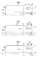
- the slits 22 are disclosed as an example of the bolt relief portions, but the present invention is not limited to the same, and can be made to be the modified examples shown in Fig. 6 through Fig. 8 for example.
- long holes 28 are provided in the upper flange 16UF of the ceiling plate portion 16U.
- the ceiling plate portion 16U of the bracket 16 is fastened and fixed to the top wall 14U of the radiator support upper member 14 by the bolts 20 in a state in which the bolts 20 are inserted-through the front end sides of the long holes 28. Accordingly, the rear side portions, with respect to the portions (the front end portions) that the bolts 20 are passed through, at the long holes 28 correspond to the bolt relief portions in the present invention.
- stepped slits 30 are provided in the upper flange 16UF of the ceiling plate portion 16U.
- the stepped slits 30 are a shape in which a bolt hole 30A, through which the bolt 20 is inserted, and a narrow-width slit 30B, that is formed from the rear end of the bolt hole 30A to the rear end of the upper flange 16UF, are connected.
- the widths of the slits 30B are smaller than the diameters of the bolts 20 (the bolt holes 30A).
- the slits 30B correspond to the bolt relief portions in the present invention.
- the load, by which the fixing (restraining) of the bracket 16 by the bolts 20 is cancelled is set by the fastening load of the bolts 20 and by the slits 30B.
- the sum of the fastening load of the bolts 20 and the load of the bolts 20 moving relatively while pushing open the slits 30B (the drawing load) is made to be the load by which the fixing (restraining) of the bracket 16 by the bolts 20 is cancelled.
- the aforementioned drawing load can also be interpreted as a portion of the load generated at the time of absorbing the collision energy of the collision body I.
- the energy absorption load can be controlled by utilizing the aforementioned drawing load that is generated by the edge portions of the slits 30B and the bolts 20 at the bracket 16.
- stepped holes 32 are provided in the upper flange 16UF of the ceiling plate portion 16U.
- the stepped holes 32 are a shape in which a narrow-width long hole 32B, that is long in the front-rear direction, is connected to the rear end of a bolt hole 32A through which the bolt 20 is inserted.
- the widths of the long holes 32B are smaller than the diameters of the bolts 20 (the bolt holes 32A).
- the long holes 32B correspond to the bolt relief portions in the present invention.
- operation and effects that are similar to the second modified example are obtained.
- a bead 34 at which the projecting height of a front end portion 34F gradually decreases toward the front, is provided at the bottom plate portion 16L instead of the bead 26.
- the projecting height from the bottom plate portion 16L is constant.
- the deformation in the direction in which the angle formed by the front plate portion 16F and the bottom plate portion 16L contracts, to be obstructed by the bead 34. Namely, at the bracket 16 that is provided with the bead 34, by an even lower load, deformation (collapsing like the crushing of a box) arises in the direction of permitting deformation of the front end of the hood 12.
- a bead 36 whose projecting height gradually decreases toward the front over the entire length, is provided at the bottom plate portion 16L instead of the bead 26.
- the projecting height of the bead 36 gradually decreases, it is difficult for the deformation, in the direction in which the angle formed by the front plate portion 16F and the bottom plate portion 16L contracts, to be obstructed by the bead 36. Namely, at the bracket 16 that is provided with the bead 36, by an even lower load, deformation (collapsing like the crushing of a box) arises in the direction of permitting deformation of the front end of the hood 12.
- the fourth and fifth modified examples show examples in which the projecting heights of the front ends of the beads 34, 36 are substantially 0, but are not limited to this, and, for example, may be structures in which the projecting heights of the front ends of the beads 34, 36 are greater than 0.
- a bead 38 that projects-out downward is provided at the bottom plate portion 16L instead of the bead 26 that projects-out upward.
- the downwardly projecting height of the bead 38 from the bottom plate portion 16L gradually decreases toward the rear.
- the projecting height of the bead 36 gradually decreases, it is difficult for the deformation, in the direction in which the angle formed by the bottom plate portion 16L and the lower flange 16LF contracts, to be obstructed by the bead 38 even though the bead 38 projects-out downward.
- deformation at the bracket 16 that is provided with the bead 38, by a low load, deformation (collapsing like the crushing of a box) arises in the direction of permitting deformation of the front end of the hood 12.
- the sixth modified example illustrates an example in which the projecting height of the rear end of the bead 38 is substantially 0, but is not limited to this, and, for example, may be a structure in which the projecting height of the rear end of the bead 38 is greater than 0.
- the above-described embodiment illustrates an example in which the horn 18 is mounted as a part to the bracket 16, but the present invention is not limited to this, and may be structured such that, for example, a part such as a front monitoring radar (a distance sensor) or the like is mounted to the bracket 16.
- a part such as a front monitoring radar (a distance sensor) or the like is mounted to the bracket 16.
- the above-described embodiment illustrates an example in which the hood 12 closes the engine room 11, but the present invention is not limited to this, and may be a structure that closes, for example, a cargo compartment provided at the vehicle front portion, or a space that houses a battery or the like instead of the engine (power unit).
Landscapes
- Engineering & Computer Science (AREA)
- Mechanical Engineering (AREA)
- Chemical & Material Sciences (AREA)
- Combustion & Propulsion (AREA)
- Transportation (AREA)
- Body Structure For Vehicles (AREA)
- Superstructure Of Vehicle (AREA)
Abstract

Description
- The present invention relates to a vehicle body front portion structure in which a bracket for parts mounting is fixed to a skeleton member beneath a hood front end portion.
- There is known a front grill structure for an automobile in which the rear end of a stay is fixed to the front wall of an upper member to which the upper end of a radiator is fixed, and a horn is mounted to this stay. (See, for example,
Japanese Patent Application Laid-Open No. 2009-286241 Japanese Patent Application Laid-Open No. 2007-55331 - By the way, in a deformation mode in which the front end portion of the hood is bent, when a bracket for parts mounting that is disposed beneath the hood interferes with the hood that is in the process of deforming, it becomes a cause of an increase in the generated load that accompanies the absorption of energy.
- An object of the present invention is to obtain a vehicle body front portion structure that, when an impact is inputted to a hood front end, can absorb impact energy by a needed load even while the hood interferes with a bracket for parts mounting.
- A vehicle body front portion structure relating to a first aspect of the present invention comprises: a hood member that covers a front portion of a vehicle from an upper side; a skeleton member that has a top wall facing an upper side in a vehicle up-down direction and a front wall facing a front side in a vehicle front-rear direction, and that is long along a vehicle transverse direction, and that is disposed at a vehicle lower side with respect to a front end side, in the vehicle front-rear direction, of the hood member; a bracket for part fixing that is structured to include a ceiling plate portion at whose rear end portion in the vehicle front-rear direction is provided an upper joining portion that is fixed to the top wall, and a bottom plate portion at whose rear end portion in the vehicle front-rear direction is provided a lower joining portion that is fixed to vehicle the front wall, and a front plate portion that connects a front end side in the vehicle front-rear direction of the ceiling plate portion and a front end side in the vehicle front-rear direction of the bottom plate portion; and fixing canceling means, provided between the upper joining portion of the ceiling plate portion and the top wall of the skeleton member, for canceling a fixed state of the upper joining portion and the top wall such that the upper joining portion is displaced relatively toward a front side in the vehicle front-rear direction with respect to the top wall, with respect to input of load of a predetermined value or more from a vehicle front upper side to the bracket.
- In accordance with the above-described aspect, the bracket forms a closed cross-sectional structure by the ceiling plate portion, bottom plate portion and front plate portion thereof, and the skeleton member front wall. When a collision body collides with the front end portion of the hood, the hood deforms such that the front end portion is bent downward. When, in the process of this deformation of the hood, the hood interferes with the (part mounted to the) bracket that is fixed so as to jut-out further toward the front side than the skeleton member, load of a predetermined value or more from the vehicle front upper side is inputted to the bracket. Thus, at the bracket, the fixing cancelling means functions, and the fixed state of the ceiling plate portion with the top wall of the skeleton member at the upper fixing portion is cancelled, and at least relative displacement of the ceiling plate portion toward the front with respect to the top wall becomes possible. Due thereto, the bracket translates from a closed cross-sectional structure to a state of (that is near) cantilever-support in which the lower fixing portion of the bottom plate portion is fixed to the skeleton member, and thereafter, the bracket is deformed, following the deformation of the hood front end, by a low load. Due thereto, the deformation stroke of the hood front end portion is ensured, and absorption of the collision energy of the collision body to the hood front end portion is achieved.
- In this way, in the vehicle body front portion structure relating to the above-described aspect, when an impact is inputted to the hood front end, the impact energy can be absorbed by the needed load even while the hood interferes with a bracket for parts mounting.
- The above-described aspect may be structured such that the fixing canceling means is structured to include a fastening structure by a bolt that fixes the ceiling plate portion to the top wall by a predetermined fastening load, and a bolt relief portion that is connected, at a rear side in the vehicle front-rear direction, to a portion through which the bolt is inserted at the ceiling plate portion.
- In accordance with the above-described aspect, usually, the ceiling plate portion of the bracket is fixed firmly to the top wall of the skeleton member by the fastening structure by the bolt. Due thereto, the needed mounting rigidity is ensured. Further, a predetermined input load to the bracket, by which the fixing is cancelled, is set by the fastening load of the bolt. When fixing by the fastening structure by the bolt is cancelled, due to the bolt moving to the bolt relief portion, relative displacement of the ceiling plate portion toward the vehicle front side with respect to the top wall is permitted by a low load.
- The above-described aspect may be structured such that the lower fastening portion is fixed to the front wall of the skeleton member at a flange portion that is formed by a rear end portion, in the vehicle front-rear direction, of the bottom plate portion being folded-over downward in the vehicle up-down direction, and, at the bottom plate portion, a bead, that is long in the vehicle front-rear direction and is convex toward an upper side in the vehicle up-down direction, is formed from the front plate portion to the flange portion.
- In accordance with the above-described aspect, the rigidity of the bracket itself is ensured by the bead that is formed at the bottom plate portion from the front wall to the flange portion. Due to the bracket, that has translated to the cantilevered state due to the collision of the collision body as described above, deforming such that the corner portion of the flange portion and the bottom plate portion bends, downward deformation of the hood front end portion is permitted. Here, because the bead that is formed at the bottom plate portion is convex upwardly, the bead is not nipped between the bottom plate portion and the flange portion that deform so as to bend as described above. Namely, due to the above-described bead, a function of improving the supporting rigidity of a part by the bracket, and a function of not impeding deformation of the bracket at the time of a collision of a collision body, can both be achieved.
- The above-described aspect may be structured such that a projecting height of the bead from the bottom plate portion at the front plate portion side is smaller than a projecting height from the bottom plate portion at the flange portion side.
- In accordance with the above-described aspect, due to the bracket, that has translated to the cantilevered state due to the collision of the collision body as described above, deforming such that the front plate portion and the bottom plate portion are bent also in directions of approaching, downward deformation of the hood front end portion is permitted. Here, because the projecting height of the bead from the bottom plate portion is lower at the front end side thereof than the rear end side, it is difficult for deformation of the bracket, in the above-described direction in which the front plate portion and the bottom plate portion approach, to be impeded.
- The above-described aspect may structured such that, at the ceiling plate portion, a bead, that is long in the vehicle front-rear direction and is convex toward an upper side in the vehicle up-down direction, is formed from the front plate portion to the upper joining portion.
- In accordance with the above-described aspect, the rigidity of the bracket itself is ensured by the bead that is formed at the ceiling plate portion from the front wall to the flange portion. Due to the bracket, that has translated to the cantilevered state due to the collision of the collision body as described above, deforming such that the angle formed by the ceiling plate portion and the front plate portion widens, downward deformation of the hood front end portion is permitted. Here, because the bead that is formed at the ceiling plate portion is convex upwardly, the bead does not receive pulling between the ceiling plate portion and the front plate portion so as to resist the deformation to widen the angle as described above. Namely, a function of improving the supporting rigidity of a part by the bracket, and a function of not impeding deformation of the bracket at the time of a collision of a collision body, can both be achieved.
- As described above, the vehicle body front portion structure relating to the present invention has the excellent effect that, when an impact is inputted to a hood front end, impact energy can be absorbed by the needed load even while the hood interferes with a bracket for parts mounting.
-
-
Fig. 1A is a side sectional view showing a vehicle body front portion structure relating to an embodiment of the present invention. -
Fig. 1B is a side sectional view showing an impact absorbing state at the vehicle body front portion structure relating to the embodiment of the present invention. -
Fig. 2A is a partially cut-away side view showing, in an enlarged manner, main portions of the vehicle body front portion structure relating to the embodiment of the present invention. -
Fig. 2B is a partially cut-away side view showing, in an enlarged manner, a deformed state of a bracket that structures the vehicle body front portion structure relating to the embodiment of the present invention. -
Fig. 3 is a plan view showing a front portion of an automobile to which the vehicle body front portion structure relating to the embodiment of the present invention is applied. -
Fig. 4 is a perspective view of the bracket that structures the vehicle body front portion structure relating to the embodiment of the present invention. -
Fig. 5 is a plan view of the bracket that structures the vehicle body front portion structure relating to the embodiment of the present invention. -
Fig. 6 is a plan view showing a first modified example of the vehicle body front portion structure relating to the embodiment of the present invention. -
Fig. 7 is a plan view showing a second modified example of the vehicle body front portion structure relating to the embodiment of the present invention. -
Fig. 8 is a plan view showing a third modified example of the vehicle body front portion structure relating to the embodiment of the present invention. -
Fig. 9 is a side view showing a fourth modified example of the vehicle body front portion structure relating to the embodiment of the present invention. -
Fig. 10 is a side view showing a fifth modified example of the vehicle body front portion structure relating to the embodiment of the present invention. -
Fig. 11 is a side view showing a sixth modified example of the vehicle body front portion structure relating to the embodiment of the present invention. - A vehicle body
front portion structure 10 relating to an embodiment of the present invention is described on the basis ofFig. 1 through Fig. 5 . Note that arrow FR that is written appropriately in the drawings indicates the front direction in the vehicle front-rear direction, arrow UP indicates the upward direction in the vehicle up-down direction, and arrow W indicates the vehicle transverse direction, respectively. In the following explanation, when front-rear and up-down directions are used, they indicate the front and the rear in the vehicle front-rear direction and upward and downward in the vehicle up-down direction, unless specially mentioned. - A front portion of an automobile V to which the vehicle body
front portion structure 10 is applied is shown in a plan view inFig. 3 . A sectional view along line 1A-1A ofFig. 3 is shown inFig. 1A . As shown in these drawings, the automobile V has ahood 12 that serves as a hood member that closes, from the upper side, an engine room 11 that serves as an opening portion that opens toward the vehicle upper side. Thehood 12 is structured with anouter panel 120 and an inner panel 12I being main portions thereof. Although not illustrated, thehood 12 is supported, at the rear end side, at the vehicle body so as to be rotatable around an axis that runs along the vehicle transverse direction, and opens and closes the engine room 11 due to this rotation with respect to the vehicle body. - Further, an unillustrated striker is provided so as to project-out downwardly at the front end side of the
hood 12. Due to this striker being engaged with a latch at the vehicle body side, thehood 12 is locked in a state of closing the engine room 11. The automobile V travels in a state in which the engine room 11 is closed by thehood 12. - A radiator support
upper member 14, that serves as a skeleton member and that is long along the vehicle transverse direction, is disposed at the lower side in the vehicle up-down direction with respect to afront end portion 12F of thehood 12. More concretely, the radiator supportupper member 14 is disposed directly in front of the mounted region of the striker at thehood 12. The radiator supportupper member 14 is a structure that supports the upper end side of an unillustrated air-cooled heat exchanger such as a radiator or a condenser for the air conditioning unit or the like. - The radiator support
upper member 14 is structured to include atop wall 14U that faces upward and afront wall 14F that faces forward. In the present embodiment, the radiator supportupper member 14 forms a closed cross-sectional structure that is substantially rectangular in side sectional view, by thetop wall 14U and thefront wall 14F and abottom wall 14L and arear wall 14R. - A
bracket 16 is mounted to the radiator supportupper member 14 so as to project-out toward the front side in the vehicle front-rear direction with respect to the radiator supportupper member 14. Thebracket 16 holds ahorn 18, that is a warning device that serves as a part, at the predetermined position with respect to the vehicle body shown inFig. 1A andFig. 3 . - As shown in
Fig. 4 , thisbracket 16 is structured to include afront plate portion 16F that faces thefront wall 14F of the radiator supportupper member 14, aceiling plate portion 16U that extends toward the rear from the upper end of thefront plate portion 16F, and abottom plate portion 16L that extends toward the rear from the lower end of thefront plate portion 16F. As shown inFig. 2A , thefront plate portion 16F, thebottom plate portion 16L and theceiling plate portion 16U of thebracket 16 are a structure that, with thefront wall 14F of the radiator supportupper member 14, forms a closed cross-sectional CS that is substantially rectangular in side view. - This
bracket 16 is fixed to the radiator supportupper member 14 at an upper flange 16UF, that serves as an upper fixing portion and is provided at the rear end side of theceiling plate portion 16U, and a lower flange 16LF, that serves as a lower fixing portion and is provided at the rear end side of thebottom plate portion 16L. The upper flange 16UF is superposed on thetop wall 14U of the radiator supportupper member 14 and is fixed to thetop wall 14U by fastening usingbolts 20. - Concretely, as shown in
Fig. 2A , the upper flange 16UF is extended rearward so as to form the same surface from the portion that structures the closed cross-section CS at theceiling plate portion 16U, and has bolt through portions through which the bolts 20 (seeFig. 2A ) are passed. The bolt through portions in this embodiment are made to beslits 22 that are long in the front-rear direction and that open rearward. The twoslits 22 are formed in parallel in the vehicle transverse direction at the upper flange 16UF that is fastened by the twobolts 20 that are disposed so as to be apart in the vehicle transverse direction. - The
ceiling plate portion 16U is fastened and fixed to thetop wall 14U due to thebolts 20 being passed-through the front end portions of theslits 22 andbolt holes 14H that are formed in thetop wall 14U, and being screwed-together with weld nuts 21 that are provided at the lower surface side of thetop wall 14U. As shown inFig. 5 as well, the rear side portions with respect tofront end portions 22A, that are the portions that thebolts 20 are passed-through at therespective slits 22, correspond to bolt relief portions in the present invention. Theslits 22 can also be interpreted as being openings in which rectangular slits of the same width as the diameters of the bolt holes are provided continuously at the rear of the circular bolt holes. - The lower flange 16LF is formed as if the rear end portion of the
bottom plate portion 16L were folded-over downward. This lower flange 16LF is fixed to thefront wall 14F by spot welding, in a state of being superposed on thefront wall 14F of the radiator supportupper member 14. - Further, in this embodiment,
beads ceiling plate portion 16U, thebottom plate portion 16L, respectively. Thebead 24 extends from the front end to the rear end (at least the upper flange 16UF that is described later) of theceiling plate portion 16U. Thebead 26 extends from the front end to the rear end (the lower flange 16LF that is described later) of thebottom plate portion 16L. In this embodiment, thesingle bead 24 is disposed at the vehicle transverse direction central portion of theceiling plate portion 16U so as to be sandwiched in the vehicle transverse direction by the pair ofslits 22. Further, thebead 26 is disposed at the vehicle transverse direction central portion of thebottom plate portion 16L. As shown inFig. 4 , thesebead 24,bead 26 are made to be convex beads that project-out upwardly from theceiling plate portion 16U, thebottom plate portion 16L, respectively, and that open downward. - The support rigidity of the
bracket 16 needed for thehorn 18 is ensured by the structure that forms the closed cross-section CS, the structure of providing the upper andlower bead 24,bead 26, and the structure of mounting to the radiator supportupper member 14 by thebolts 20 and spot welding, as described above. - Here, the fastening load of the
bracket 16 to the radiator supportupper member 14 by thebolts 20 is set (managed) to a prescribed fastening load. This prescribed fastening load is set as a load by which the fastened and fixed state of thebracket 16 to the radiator supportupper member 14 by thebolts 20 is cancelled when a load of a predetermined value or more is inputted from the front upper side toward the rear lower side to the front end side of the bracket 16 (the closed cross-section CS). This load is made to be a load that is sufficiently small with respect to load inputted to thebracket 16 via thehood 12 in a pedestrian femoral region protection test, and is sufficiently large with respect to load that is inputted to thebracket 16 from thehorn 18 in the usual usage state of the automobile V. The fixing cancelling means in the present invention is structured by the setting of this fastening load and by the slits 22 (bolt relief portions). - Operation of the present embodiment is described next.
- In the vehicle body
front portion structure 10 of the above-described structure, usually, a state in which thehorn 18 is supported at the radiator supportupper member 14 via thebracket 16 is maintained. Thebracket 16 is fastened to the radiator supportupper member 14 by the aforementioned prescribed load by thebolts 20, and thebeads ceiling plate portion 16U and thebottom plate portion 16L, respectively. Therefore, thebracket 16 can ensure a sufficient supporting rigidity of thehorn 18. Due thereto, in the vehicle bodyfront portion structure 10, the occurrence of chattering noise that accompanies operation of thehorn 18 is prevented or effectively suppressed. Further, the durability of thebracket 16 improves due to thebeads - In a pedestrian femoral region protection test, when a collision body I collides with the
front end portion 12F of thehood 12 as shown inFig. 1B , thehood 12 is deformed such that the portion, that is further toward the front side than the region that is restrained at the vehicle body by the striker, is bent downwardly. The collision energy due to the collision of the collision body I is absorbed by this deformation. - Accompanying the above-described deformation of the
hood 12, the front end portion of thehood 12 collides with thebracket 16, from the front upper side. Therefore, load of the aforementioned predetermined value or more is applied to thebracket 16 from the front upper side. Thus, thebracket 16 bendingly deforms such that the closed cross-section CS is crushed as shown inFig. 1B while the fixed state of theceiling plate portion 16U by thebolts 20 is cancelled and the rear portion of theceiling plate portion 16U is pulled-out forward so as to slide on thetop wall 14U. - Namely, at the
bracket 16, the angle formed by theceiling plate portion 16U and thefront plate portion 16F widens, the angle formed by thefront plate portion 16F and thebottom plate portion 16L contracts, and the angle formed by thebottom plate portion 16L and the lower flange 16LF contracts, and deformation arises in the direction of permitting further deformation of the front end of the hood 12 (collapsing like the crushing of a box). Due thereto, even after thehood 12 contacts thebracket 16, the impact absorbing stroke of the collision body I is ensured. - Here, in the vehicle body
front portion structure 10, when load of the predetermined value or more is applied to thebracket 16 from the front upper side, the fixed state of theceiling plate portion 16U, by thebolts 20, of thebracket 16 is cancelled, and therefore, the above-described deformation is generated by a low load at thebracket 16. Namely, because thebracket 16 translates from the supported structure by the upper flange 16UF and the lower flange 16LF to a structure of (that can be approximated as) cantilever support by the lower flange 16LF, thebracket 16 is deformed by a low load, as compared with a structure in which this translation does not occur. - Further, in the vehicle body
front portion structure 10, because thebead 26 of thebottom plate portion 16L projects-out upwardly, the bead is not nipped-in between thebottom plate portion 16L and the lower flange 16LF at which the angle formed thereby contracts as described above. Therefore, thebead 26 does not obstruct the deformation that contracts the aforementioned angle formed by thebottom plate portion 16L and the lower flange 16LF of thebracket 16. In this way, in the vehicle bodyfront portion structure 10, in a structure that ensures the supporting rigidity of thehorn 18 by thebracket 16, the load needed to deform thebracket 16 after contact of thehood 12 can be kept small. - Further, in the vehicle body
front portion structure 10, thebead 24 of theceiling plate portion 16U projects-out upward, and therefore, between theceiling plate portion 16U and thefront plate portion 16F at which the angle formed thereby attempts to widen as described above, the bead does not receive pulling that resists this widening of the angle. For this reason as well, in a structure that ensures the supporting rigidity of thehorn 18 by thebracket 16, this contributes to keeping small the load that is needed to deform thebracket 16 after contact of thehood 12. - Namely, in a comparative example that uses, for example, a bracket that forms a simple closed cross-sectional structure, because the load needed for deformation is large, downward deformation of the
hood 12 is restrained, and bottoming arises or the peak load that is applied to the collision body I is increased. In contrast, in the vehicle bodyfront portion structure 10 that uses thebracket 16, the load needed for deformation of thebracket 16 can be made to be sufficiently small as compared with the comparative example, and therefore, even after contact of the front end portion of thehood 12, the effects on the performance of absorbing the collision energy of the collision body I by the deformation of thehood 12 are small. - In this way, in the vehicle body
front portion structure 10 relating to the embodiment, when the collision body I collides with the front end of thehood 12, the impact energy can be absorbed by the needed load even while thehood 12 interferes with thebracket 16. - In the above-described embodiment, the
slits 22 are disclosed as an example of the bolt relief portions, but the present invention is not limited to the same, and can be made to be the modified examples shown inFig. 6 through Fig. 8 for example. - In a first modified example shown in
Fig. 6 , instead of theslits 22,long holes 28 are provided in the upper flange 16UF of theceiling plate portion 16U. In this modified example, theceiling plate portion 16U of thebracket 16 is fastened and fixed to thetop wall 14U of the radiator supportupper member 14 by thebolts 20 in a state in which thebolts 20 are inserted-through the front end sides of thelong holes 28. Accordingly, the rear side portions, with respect to the portions (the front end portions) that thebolts 20 are passed through, at thelong holes 28 correspond to the bolt relief portions in the present invention. - In a second modified example shown in
Fig. 7 , instead of theslits 22 that are made to be a uniform width at the respective portions in the longitudinal direction, steppedslits 30 are provided in the upper flange 16UF of theceiling plate portion 16U. The stepped slits 30 are a shape in which abolt hole 30A, through which thebolt 20 is inserted, and a narrow-width slit 30B, that is formed from the rear end of thebolt hole 30A to the rear end of the upper flange 16UF, are connected. The widths of theslits 30B are smaller than the diameters of the bolts 20 (the bolt holes 30A). In the second modified example, theslits 30B correspond to the bolt relief portions in the present invention. - In this second modified example, the load, by which the fixing (restraining) of the
bracket 16 by thebolts 20 is cancelled, is set by the fastening load of thebolts 20 and by theslits 30B. Namely, the sum of the fastening load of thebolts 20 and the load of thebolts 20 moving relatively while pushing open theslits 30B (the drawing load) is made to be the load by which the fixing (restraining) of thebracket 16 by thebolts 20 is cancelled. Note that the aforementioned drawing load can also be interpreted as a portion of the load generated at the time of absorbing the collision energy of the collision body I. Namely, in a structure in which the load generated at thehood 12 alone is small (insufficient), the energy absorption load (stroke) can be controlled by utilizing the aforementioned drawing load that is generated by the edge portions of theslits 30B and thebolts 20 at thebracket 16. - In a third modified example shown in Fig. 18, instead of the
slits 22 that are made to be a uniform width at the respective portions in the longitudinal direction, steppedholes 32 are provided in the upper flange 16UF of theceiling plate portion 16U. The stepped holes 32 are a shape in which a narrow-widthlong hole 32B, that is long in the front-rear direction, is connected to the rear end of abolt hole 32A through which thebolt 20 is inserted. The widths of thelong holes 32B are smaller than the diameters of the bolts 20 (the bolt holes 32A). In the third modified example, thelong holes 32B correspond to the bolt relief portions in the present invention. In the third modified example, operation and effects that are similar to the second modified example are obtained. - The above-described embodiment discloses an example in which the
bead 26, whose projecting height is constant along the entire length, is formed at thebottom plate portion 16L, but the present invention is not limited to the same, and can be made to be the modified examples shown inFig. 9 through Fig. 11 for example. - In a fourth modified example shown in
Fig. 9 , abead 34, at which the projecting height of afront end portion 34F gradually decreases toward the front, is provided at thebottom plate portion 16L instead of thebead 26. At the portion other than thefront end portion 34F at thebead 34, the projecting height from thebottom plate portion 16L is constant. In this modified example, because the projecting height of thefront end portion 34F gradually decreases, it is difficult for the deformation, in the direction in which the angle formed by thefront plate portion 16F and thebottom plate portion 16L contracts, to be obstructed by thebead 34. Namely, at thebracket 16 that is provided with thebead 34, by an even lower load, deformation (collapsing like the crushing of a box) arises in the direction of permitting deformation of the front end of thehood 12. - In a fifth modified example shown in
Fig. 10 , abead 36, whose projecting height gradually decreases toward the front over the entire length, is provided at thebottom plate portion 16L instead of thebead 26. In this modified example, because the projecting height of thebead 36 gradually decreases, it is difficult for the deformation, in the direction in which the angle formed by thefront plate portion 16F and thebottom plate portion 16L contracts, to be obstructed by thebead 36. Namely, at thebracket 16 that is provided with thebead 36, by an even lower load, deformation (collapsing like the crushing of a box) arises in the direction of permitting deformation of the front end of thehood 12. - Note that the fourth and fifth modified examples show examples in which the projecting heights of the front ends of the
beads beads - In a sixth modified example shown in
Fig. 11 , abead 38 that projects-out downward is provided at thebottom plate portion 16L instead of thebead 26 that projects-out upward. The downwardly projecting height of thebead 38 from thebottom plate portion 16L gradually decreases toward the rear. In this modified example, because the projecting height of thebead 36 gradually decreases, it is difficult for the deformation, in the direction in which the angle formed by thebottom plate portion 16L and the lower flange 16LF contracts, to be obstructed by thebead 38 even though thebead 38 projects-out downward. Namely, at thebracket 16 that is provided with thebead 38, by a low load, deformation (collapsing like the crushing of a box) arises in the direction of permitting deformation of the front end of thehood 12. - Note that the sixth modified example illustrates an example in which the projecting height of the rear end of the
bead 38 is substantially 0, but is not limited to this, and, for example, may be a structure in which the projecting height of the rear end of thebead 38 is greater than 0. - Note that the above-described embodiment illustrates an example in which the
horn 18 is mounted as a part to thebracket 16, but the present invention is not limited to this, and may be structured such that, for example, a part such as a front monitoring radar (a distance sensor) or the like is mounted to thebracket 16. - Further, the above-described embodiment illustrates an example in which the
hood 12 closes the engine room 11, but the present invention is not limited to this, and may be a structure that closes, for example, a cargo compartment provided at the vehicle front portion, or a space that houses a battery or the like instead of the engine (power unit).
Claims (5)
- A vehicle body front portion structure comprising:a hood member that covers a front portion of a vehicle from an upper side;a skeleton member that has a top wall facing an upper side in a vehicle up-down direction and a front wall facing a front side in a vehicle front-rear direction, and that is long along a vehicle transverse direction, and that is disposed at a vehicle lower side with respect to a front end side, in the vehicle front-rear direction, of the hood member;a bracket for part fixing that is structured to include a ceiling plate portion at whose rear end portion in the vehicle front-rear direction is provided an upper joining portion that is fixed to the top wall, and a bottom plate portion at whose rear end portion in the vehicle front-rear direction is provided a lower joining portion that is fixed to the front wall, and a front plate portion that connects a front end side in the vehicle front-rear direction of the ceiling plate portion and a front end side in the vehicle front-rear direction of the bottom plate portion; andfixing canceling means, provided between the upper joining portion of the ceiling plate portion and the top wall of the skeleton member, for canceling a fixed state of the upper joining portion and the top wall such that the upper joining portion is displaced relatively toward a front side in the vehicle front-rear direction with respect to the top wall, with respect to input of load of a predetermined value or more from a vehicle front upper side to the bracket.
- The vehicle body front portion structure of claim 1, wherein the fixing canceling means is structured to include a fastening structure by a bolt that fixes the ceiling plate portion to the top wall by a predetermined fastening load, and a bolt relief portion that is connected, at a rear side in the vehicle front-rear direction, to a portion through which the bolt is inserted at the ceiling plate portion.
- The vehicle body front portion structure of claim 1 or claim 2, wherein
the lower fastening portion is fixed to the front wall of the skeleton member at a flange portion that is formed by a rear end portion, in the vehicle front-rear direction, of the bottom plate portion being folded-over downward in the vehicle up-down direction, and
at the bottom plate portion, a bead, that is long in the vehicle front-rear direction and is convex toward an upper side in the vehicle up-down direction, is formed from the front plate portion to the flange portion. - The vehicle body front portion structure of claim 3, wherein a projecting height of the bead from the bottom plate portion at the front plate portion side is smaller than a projecting height from the bottom plate portion at the flange portion side.
- The vehicle body front portion structure of any one of claim 1 through claim 4, wherein, at the ceiling plate portion, a bead, that is long in the vehicle front-rear direction and is convex toward an upper side in the vehicle up-down direction, is formed from the front plate portion to the upper joining portion.
Applications Claiming Priority (1)
| Application Number | Priority Date | Filing Date | Title |
|---|---|---|---|
| PCT/JP2010/062717 WO2012014297A1 (en) | 2010-07-28 | 2010-07-28 | Structure for vehicle body front portion |
Publications (3)
| Publication Number | Publication Date |
|---|---|
| EP2599666A1 true EP2599666A1 (en) | 2013-06-05 |
| EP2599666A4 EP2599666A4 (en) | 2013-12-18 |
| EP2599666B1 EP2599666B1 (en) | 2015-02-11 |
Family
ID=45529542
Family Applications (1)
| Application Number | Title | Priority Date | Filing Date |
|---|---|---|---|
| EP10855307.4A Not-in-force EP2599666B1 (en) | 2010-07-28 | 2010-07-28 | Structure for vehicle body front portion |
Country Status (3)
| Country | Link |
|---|---|
| EP (1) | EP2599666B1 (en) |
| JP (1) | JP5146613B2 (en) |
| WO (1) | WO2012014297A1 (en) |
Cited By (4)
| Publication number | Priority date | Publication date | Assignee | Title |
|---|---|---|---|---|
| FR3039799A1 (en) * | 2015-08-03 | 2017-02-10 | Peugeot Citroen Automobiles Sa | ARRANGEMENT FOR MOUNTING A SOUND WARNING ON A VEHICLE |
| US9834170B1 (en) | 2016-10-27 | 2017-12-05 | Toyota Motor Engineering & Manufacturing North America, Inc. | Collapsible radiator support brackets for pedestrian safety |
| US9855914B1 (en) | 2016-07-08 | 2018-01-02 | Toyota Motor Engineering & Manufacturing North America, Inc. | Deformable energy absorber structures for front hood assemblies of vehicles |
| WO2024236233A1 (en) * | 2023-05-15 | 2024-11-21 | Stellantis Auto Sas | Bumper without any retaining screws |
Families Citing this family (4)
| Publication number | Priority date | Publication date | Assignee | Title |
|---|---|---|---|---|
| JP5373004B2 (en) * | 2011-07-20 | 2013-12-18 | 本田技研工業株式会社 | Auto body front structure |
| JP6171942B2 (en) * | 2014-01-14 | 2017-08-02 | トヨタ自動車株式会社 | Vehicle front structure |
| JP6583696B2 (en) * | 2017-06-16 | 2019-10-02 | 本田技研工業株式会社 | Vehicle sensor support bracket |
| JP2023179252A (en) * | 2022-06-07 | 2023-12-19 | トヨタ自動車株式会社 | vehicle |
Family Cites Families (10)
| Publication number | Priority date | Publication date | Assignee | Title |
|---|---|---|---|---|
| JP2520916Y2 (en) * | 1991-10-22 | 1996-12-18 | ダイハツ工業株式会社 | Horn mounting structure |
| JPH10236335A (en) * | 1997-02-25 | 1998-09-08 | Toyota Motor Corp | Vehicle release structure |
| JP2004106718A (en) * | 2002-09-19 | 2004-04-08 | Fuji Heavy Ind Ltd | Automotive horn mounting structure |
| JP4299075B2 (en) * | 2003-08-26 | 2009-07-22 | 本田技研工業株式会社 | Mounting structure for vehicle horn |
| JP4289168B2 (en) * | 2004-02-02 | 2009-07-01 | 株式会社デンソー | Front end structure of the vehicle |
| JP4645135B2 (en) * | 2004-09-30 | 2011-03-09 | マツダ株式会社 | Automotive hood stopper structure |
| JP2007001528A (en) * | 2005-06-27 | 2007-01-11 | Fuji Heavy Ind Ltd | Automobile horn mounting structure |
| JP2007055331A (en) | 2005-08-23 | 2007-03-08 | Suzuki Motor Corp | Vibration noise reduction structure for vehicle horn |
| JP4404827B2 (en) * | 2005-09-08 | 2010-01-27 | 本田技研工業株式会社 | Front body structure of automobile |
| JP5056588B2 (en) | 2008-05-29 | 2012-10-24 | スズキ株式会社 | Front grill structure of automobile |
-
2010
- 2010-07-28 EP EP10855307.4A patent/EP2599666B1/en not_active Not-in-force
- 2010-07-28 WO PCT/JP2010/062717 patent/WO2012014297A1/en not_active Ceased
- 2010-07-28 JP JP2011552277A patent/JP5146613B2/en not_active Expired - Fee Related
Non-Patent Citations (2)
| Title |
|---|
| No further relevant documents disclosed * |
| See also references of WO2012014297A1 * |
Cited By (5)
| Publication number | Priority date | Publication date | Assignee | Title |
|---|---|---|---|---|
| FR3039799A1 (en) * | 2015-08-03 | 2017-02-10 | Peugeot Citroen Automobiles Sa | ARRANGEMENT FOR MOUNTING A SOUND WARNING ON A VEHICLE |
| US9855914B1 (en) | 2016-07-08 | 2018-01-02 | Toyota Motor Engineering & Manufacturing North America, Inc. | Deformable energy absorber structures for front hood assemblies of vehicles |
| US9834170B1 (en) | 2016-10-27 | 2017-12-05 | Toyota Motor Engineering & Manufacturing North America, Inc. | Collapsible radiator support brackets for pedestrian safety |
| WO2024236233A1 (en) * | 2023-05-15 | 2024-11-21 | Stellantis Auto Sas | Bumper without any retaining screws |
| FR3148756A1 (en) * | 2023-05-15 | 2024-11-22 | Psa Automobiles Sa | Bumper without retaining screws. |
Also Published As
| Publication number | Publication date |
|---|---|
| EP2599666A4 (en) | 2013-12-18 |
| JP5146613B2 (en) | 2013-02-20 |
| JPWO2012014297A1 (en) | 2013-09-09 |
| EP2599666B1 (en) | 2015-02-11 |
| WO2012014297A1 (en) | 2012-02-02 |
Similar Documents
| Publication | Publication Date | Title |
|---|---|---|
| EP2599666B1 (en) | Structure for vehicle body front portion | |
| JP6511078B2 (en) | Electric car floor structure | |
| JP6304505B2 (en) | Vehicle side body structure | |
| US9242676B2 (en) | Front vehicle body reinforcing structure | |
| JP2009083687A (en) | Automotive front structure | |
| JP6269246B2 (en) | Front body structure | |
| JP2008265399A (en) | Automotive front structure | |
| JP5969417B2 (en) | Body front structure | |
| US8651559B2 (en) | Vehicle body front structure | |
| JP5630721B2 (en) | Body front structure | |
| JP2009287950A (en) | Mounting structure of radar device | |
| JP5115701B2 (en) | Body front structure | |
| JP2010047076A (en) | Vehicular front body structure | |
| JP2016147547A (en) | Pedestrian protection airbag device | |
| JP2007001563A (en) | Automobile shroud support structure | |
| JP2002331889A (en) | Car body front structure | |
| JPH07117710A (en) | Electric vehicle control unit mounting structure | |
| JP2016094107A (en) | Car cowl structure | |
| JP2009083688A (en) | Automotive front structure | |
| JP5966895B2 (en) | Automobile leg mounting structure | |
| JP2006168523A (en) | Mounting structure of tow hook for vehicle | |
| JP5062157B2 (en) | Vehicle pedal retraction control structure | |
| JP4250852B2 (en) | Vehicle fender structure | |
| JP2006224721A (en) | Front body structure of automobile | |
| JP6460164B2 (en) | Automotive front structure |
Legal Events
| Date | Code | Title | Description |
|---|---|---|---|
| PUAI | Public reference made under article 153(3) epc to a published international application that has entered the european phase |
Free format text: ORIGINAL CODE: 0009012 |
|
| 17P | Request for examination filed |
Effective date: 20120626 |
|
| AK | Designated contracting states |
Kind code of ref document: A1 Designated state(s): AL AT BE BG CH CY CZ DE DK EE ES FI FR GB GR HR HU IE IS IT LI LT LU LV MC MK MT NL NO PL PT RO SE SI SK SM TR |
|
| DAX | Request for extension of the european patent (deleted) | ||
| RIN1 | Information on inventor provided before grant (corrected) |
Inventor name: NAKANO, TAKASHI Inventor name: MIWA, SHINJI Inventor name: NAKANO, SHIROU |
|
| A4 | Supplementary search report drawn up and despatched |
Effective date: 20131119 |
|
| RIC1 | Information provided on ipc code assigned before grant |
Ipc: B62D 25/08 20060101ALI20131113BHEP Ipc: B60K 11/04 20060101ALI20131113BHEP Ipc: B60R 21/34 20110101AFI20131113BHEP Ipc: B60Q 5/00 20060101ALI20131113BHEP Ipc: B60R 19/52 20060101ALI20131113BHEP |
|
| REG | Reference to a national code |
Ref country code: DE Ref legal event code: R079 Ref document number: 602010022277 Country of ref document: DE Free format text: PREVIOUS MAIN CLASS: B60Q0005000000 Ipc: B60R0021340000 |
|
| RIC1 | Information provided on ipc code assigned before grant |
Ipc: B60R 19/52 20060101ALI20140625BHEP Ipc: B62D 25/08 20060101ALI20140625BHEP Ipc: B60R 21/34 20110101AFI20140625BHEP Ipc: B60Q 5/00 20060101ALI20140625BHEP Ipc: B60K 11/04 20060101ALI20140625BHEP |
|
| GRAP | Despatch of communication of intention to grant a patent |
Free format text: ORIGINAL CODE: EPIDOSNIGR1 |
|
| INTG | Intention to grant announced |
Effective date: 20140813 |
|
| GRAS | Grant fee paid |
Free format text: ORIGINAL CODE: EPIDOSNIGR3 |
|
| GRAA | (expected) grant |
Free format text: ORIGINAL CODE: 0009210 |
|
| AK | Designated contracting states |
Kind code of ref document: B1 Designated state(s): AL AT BE BG CH CY CZ DE DK EE ES FI FR GB GR HR HU IE IS IT LI LT LU LV MC MK MT NL NO PL PT RO SE SI SK SM TR |
|
| REG | Reference to a national code |
Ref country code: GB Ref legal event code: FG4D |
|
| REG | Reference to a national code |
Ref country code: CH Ref legal event code: EP |
|
| REG | Reference to a national code |
Ref country code: IE Ref legal event code: FG4D |
|
| REG | Reference to a national code |
Ref country code: AT Ref legal event code: REF Ref document number: 709813 Country of ref document: AT Kind code of ref document: T Effective date: 20150315 |
|
| REG | Reference to a national code |
Ref country code: DE Ref legal event code: R096 Ref document number: 602010022277 Country of ref document: DE Effective date: 20150326 |
|
| REG | Reference to a national code |
Ref country code: DE Ref legal event code: R084 Ref document number: 602010022277 Country of ref document: DE |
|
| REG | Reference to a national code |
Ref country code: GB Ref legal event code: 746 Effective date: 20150424 |
|
| REG | Reference to a national code |
Ref country code: DE Ref legal event code: R084 Ref document number: 602010022277 Country of ref document: DE Effective date: 20150417 |
|
| REG | Reference to a national code |
Ref country code: NL Ref legal event code: VDEP Effective date: 20150211 |
|
| REG | Reference to a national code |
Ref country code: AT Ref legal event code: MK05 Ref document number: 709813 Country of ref document: AT Kind code of ref document: T Effective date: 20150211 |
|
| REG | Reference to a national code |
Ref country code: LT Ref legal event code: MG4D |
|
| PG25 | Lapsed in a contracting state [announced via postgrant information from national office to epo] |
Ref country code: ES Free format text: LAPSE BECAUSE OF FAILURE TO SUBMIT A TRANSLATION OF THE DESCRIPTION OR TO PAY THE FEE WITHIN THE PRESCRIBED TIME-LIMIT Effective date: 20150211 Ref country code: LT Free format text: LAPSE BECAUSE OF FAILURE TO SUBMIT A TRANSLATION OF THE DESCRIPTION OR TO PAY THE FEE WITHIN THE PRESCRIBED TIME-LIMIT Effective date: 20150211 Ref country code: NO Free format text: LAPSE BECAUSE OF FAILURE TO SUBMIT A TRANSLATION OF THE DESCRIPTION OR TO PAY THE FEE WITHIN THE PRESCRIBED TIME-LIMIT Effective date: 20150511 Ref country code: HR Free format text: LAPSE BECAUSE OF FAILURE TO SUBMIT A TRANSLATION OF THE DESCRIPTION OR TO PAY THE FEE WITHIN THE PRESCRIBED TIME-LIMIT Effective date: 20150211 Ref country code: FI Free format text: LAPSE BECAUSE OF FAILURE TO SUBMIT A TRANSLATION OF THE DESCRIPTION OR TO PAY THE FEE WITHIN THE PRESCRIBED TIME-LIMIT Effective date: 20150211 Ref country code: SE Free format text: LAPSE BECAUSE OF FAILURE TO SUBMIT A TRANSLATION OF THE DESCRIPTION OR TO PAY THE FEE WITHIN THE PRESCRIBED TIME-LIMIT Effective date: 20150211 |
|
| PG25 | Lapsed in a contracting state [announced via postgrant information from national office to epo] |
Ref country code: AT Free format text: LAPSE BECAUSE OF FAILURE TO SUBMIT A TRANSLATION OF THE DESCRIPTION OR TO PAY THE FEE WITHIN THE PRESCRIBED TIME-LIMIT Effective date: 20150211 Ref country code: IS Free format text: LAPSE BECAUSE OF FAILURE TO SUBMIT A TRANSLATION OF THE DESCRIPTION OR TO PAY THE FEE WITHIN THE PRESCRIBED TIME-LIMIT Effective date: 20150611 Ref country code: NL Free format text: LAPSE BECAUSE OF FAILURE TO SUBMIT A TRANSLATION OF THE DESCRIPTION OR TO PAY THE FEE WITHIN THE PRESCRIBED TIME-LIMIT Effective date: 20150211 Ref country code: GR Free format text: LAPSE BECAUSE OF FAILURE TO SUBMIT A TRANSLATION OF THE DESCRIPTION OR TO PAY THE FEE WITHIN THE PRESCRIBED TIME-LIMIT Effective date: 20150512 Ref country code: LV Free format text: LAPSE BECAUSE OF FAILURE TO SUBMIT A TRANSLATION OF THE DESCRIPTION OR TO PAY THE FEE WITHIN THE PRESCRIBED TIME-LIMIT Effective date: 20150211 |
|
| PG25 | Lapsed in a contracting state [announced via postgrant information from national office to epo] |
Ref country code: RO Free format text: LAPSE BECAUSE OF FAILURE TO SUBMIT A TRANSLATION OF THE DESCRIPTION OR TO PAY THE FEE WITHIN THE PRESCRIBED TIME-LIMIT Effective date: 20150211 Ref country code: EE Free format text: LAPSE BECAUSE OF FAILURE TO SUBMIT A TRANSLATION OF THE DESCRIPTION OR TO PAY THE FEE WITHIN THE PRESCRIBED TIME-LIMIT Effective date: 20150211 Ref country code: DK Free format text: LAPSE BECAUSE OF FAILURE TO SUBMIT A TRANSLATION OF THE DESCRIPTION OR TO PAY THE FEE WITHIN THE PRESCRIBED TIME-LIMIT Effective date: 20150211 Ref country code: SK Free format text: LAPSE BECAUSE OF FAILURE TO SUBMIT A TRANSLATION OF THE DESCRIPTION OR TO PAY THE FEE WITHIN THE PRESCRIBED TIME-LIMIT Effective date: 20150211 Ref country code: CZ Free format text: LAPSE BECAUSE OF FAILURE TO SUBMIT A TRANSLATION OF THE DESCRIPTION OR TO PAY THE FEE WITHIN THE PRESCRIBED TIME-LIMIT Effective date: 20150211 |
|
| REG | Reference to a national code |
Ref country code: DE Ref legal event code: R097 Ref document number: 602010022277 Country of ref document: DE |
|
| PG25 | Lapsed in a contracting state [announced via postgrant information from national office to epo] |
Ref country code: PL Free format text: LAPSE BECAUSE OF FAILURE TO SUBMIT A TRANSLATION OF THE DESCRIPTION OR TO PAY THE FEE WITHIN THE PRESCRIBED TIME-LIMIT Effective date: 20150211 |
|
| PLBE | No opposition filed within time limit |
Free format text: ORIGINAL CODE: 0009261 |
|
| STAA | Information on the status of an ep patent application or granted ep patent |
Free format text: STATUS: NO OPPOSITION FILED WITHIN TIME LIMIT |
|
| 26N | No opposition filed |
Effective date: 20151112 |
|
| PG25 | Lapsed in a contracting state [announced via postgrant information from national office to epo] |
Ref country code: MC Free format text: LAPSE BECAUSE OF FAILURE TO SUBMIT A TRANSLATION OF THE DESCRIPTION OR TO PAY THE FEE WITHIN THE PRESCRIBED TIME-LIMIT Effective date: 20150211 Ref country code: SI Free format text: LAPSE BECAUSE OF FAILURE TO SUBMIT A TRANSLATION OF THE DESCRIPTION OR TO PAY THE FEE WITHIN THE PRESCRIBED TIME-LIMIT Effective date: 20150211 |
|
| REG | Reference to a national code |
Ref country code: CH Ref legal event code: PL |
|
| PG25 | Lapsed in a contracting state [announced via postgrant information from national office to epo] |
Ref country code: LU Free format text: LAPSE BECAUSE OF FAILURE TO SUBMIT A TRANSLATION OF THE DESCRIPTION OR TO PAY THE FEE WITHIN THE PRESCRIBED TIME-LIMIT Effective date: 20150728 |
|
| REG | Reference to a national code |
Ref country code: IE Ref legal event code: MM4A |
|
| PG25 | Lapsed in a contracting state [announced via postgrant information from national office to epo] |
Ref country code: CH Free format text: LAPSE BECAUSE OF NON-PAYMENT OF DUE FEES Effective date: 20150731 Ref country code: LI Free format text: LAPSE BECAUSE OF NON-PAYMENT OF DUE FEES Effective date: 20150731 |
|
| PG25 | Lapsed in a contracting state [announced via postgrant information from national office to epo] |
Ref country code: BE Free format text: LAPSE BECAUSE OF FAILURE TO SUBMIT A TRANSLATION OF THE DESCRIPTION OR TO PAY THE FEE WITHIN THE PRESCRIBED TIME-LIMIT Effective date: 20150211 |
|
| REG | Reference to a national code |
Ref country code: FR Ref legal event code: PLFP Year of fee payment: 7 |
|
| PG25 | Lapsed in a contracting state [announced via postgrant information from national office to epo] |
Ref country code: IE Free format text: LAPSE BECAUSE OF NON-PAYMENT OF DUE FEES Effective date: 20150728 |
|
| PG25 | Lapsed in a contracting state [announced via postgrant information from national office to epo] |
Ref country code: MT Free format text: LAPSE BECAUSE OF FAILURE TO SUBMIT A TRANSLATION OF THE DESCRIPTION OR TO PAY THE FEE WITHIN THE PRESCRIBED TIME-LIMIT Effective date: 20150211 |
|
| PG25 | Lapsed in a contracting state [announced via postgrant information from national office to epo] |
Ref country code: SM Free format text: LAPSE BECAUSE OF FAILURE TO SUBMIT A TRANSLATION OF THE DESCRIPTION OR TO PAY THE FEE WITHIN THE PRESCRIBED TIME-LIMIT Effective date: 20150211 Ref country code: BG Free format text: LAPSE BECAUSE OF FAILURE TO SUBMIT A TRANSLATION OF THE DESCRIPTION OR TO PAY THE FEE WITHIN THE PRESCRIBED TIME-LIMIT Effective date: 20150211 Ref country code: HU Free format text: LAPSE BECAUSE OF FAILURE TO SUBMIT A TRANSLATION OF THE DESCRIPTION OR TO PAY THE FEE WITHIN THE PRESCRIBED TIME-LIMIT; INVALID AB INITIO Effective date: 20100728 |
|
| REG | Reference to a national code |
Ref country code: FR Ref legal event code: PLFP Year of fee payment: 8 |
|
| PG25 | Lapsed in a contracting state [announced via postgrant information from national office to epo] |
Ref country code: CY Free format text: LAPSE BECAUSE OF FAILURE TO SUBMIT A TRANSLATION OF THE DESCRIPTION OR TO PAY THE FEE WITHIN THE PRESCRIBED TIME-LIMIT Effective date: 20150211 |
|
| REG | Reference to a national code |
Ref country code: FR Ref legal event code: PLFP Year of fee payment: 9 |
|
| PG25 | Lapsed in a contracting state [announced via postgrant information from national office to epo] |
Ref country code: TR Free format text: LAPSE BECAUSE OF FAILURE TO SUBMIT A TRANSLATION OF THE DESCRIPTION OR TO PAY THE FEE WITHIN THE PRESCRIBED TIME-LIMIT Effective date: 20150211 Ref country code: MK Free format text: LAPSE BECAUSE OF FAILURE TO SUBMIT A TRANSLATION OF THE DESCRIPTION OR TO PAY THE FEE WITHIN THE PRESCRIBED TIME-LIMIT Effective date: 20150211 Ref country code: PT Free format text: LAPSE BECAUSE OF FAILURE TO SUBMIT A TRANSLATION OF THE DESCRIPTION OR TO PAY THE FEE WITHIN THE PRESCRIBED TIME-LIMIT Effective date: 20150211 |
|
| PG25 | Lapsed in a contracting state [announced via postgrant information from national office to epo] |
Ref country code: AL Free format text: LAPSE BECAUSE OF FAILURE TO SUBMIT A TRANSLATION OF THE DESCRIPTION OR TO PAY THE FEE WITHIN THE PRESCRIBED TIME-LIMIT Effective date: 20150211 |
|
| PGFP | Annual fee paid to national office [announced via postgrant information from national office to epo] |
Ref country code: FR Payment date: 20210611 Year of fee payment: 12 Ref country code: IT Payment date: 20210610 Year of fee payment: 12 |
|
| PGFP | Annual fee paid to national office [announced via postgrant information from national office to epo] |
Ref country code: GB Payment date: 20210630 Year of fee payment: 12 |
|
| PGFP | Annual fee paid to national office [announced via postgrant information from national office to epo] |
Ref country code: DE Payment date: 20210629 Year of fee payment: 12 |
|
| REG | Reference to a national code |
Ref country code: DE Ref legal event code: R119 Ref document number: 602010022277 Country of ref document: DE |
|
| GBPC | Gb: european patent ceased through non-payment of renewal fee |
Effective date: 20220728 |
|
| PG25 | Lapsed in a contracting state [announced via postgrant information from national office to epo] |
Ref country code: FR Free format text: LAPSE BECAUSE OF NON-PAYMENT OF DUE FEES Effective date: 20220731 |
|
| PG25 | Lapsed in a contracting state [announced via postgrant information from national office to epo] |
Ref country code: GB Free format text: LAPSE BECAUSE OF NON-PAYMENT OF DUE FEES Effective date: 20220728 Ref country code: DE Free format text: LAPSE BECAUSE OF NON-PAYMENT OF DUE FEES Effective date: 20230201 |
|
| PG25 | Lapsed in a contracting state [announced via postgrant information from national office to epo] |
Ref country code: IT Free format text: LAPSE BECAUSE OF NON-PAYMENT OF DUE FEES Effective date: 20220728 |