EP2599662A1 - Vehicle seat - Google Patents
Vehicle seat Download PDFInfo
- Publication number
- EP2599662A1 EP2599662A1 EP11803632.6A EP11803632A EP2599662A1 EP 2599662 A1 EP2599662 A1 EP 2599662A1 EP 11803632 A EP11803632 A EP 11803632A EP 2599662 A1 EP2599662 A1 EP 2599662A1
- Authority
- EP
- European Patent Office
- Prior art keywords
- wall
- frame
- force
- receiving member
- vehicle seat
- Prior art date
- Legal status (The legal status is an assumption and is not a legal conclusion. Google has not performed a legal analysis and makes no representation as to the accuracy of the status listed.)
- Withdrawn
Links
- 230000003014 reinforcing effect Effects 0.000 claims abstract description 68
- 238000009751 slip forming Methods 0.000 claims description 4
- 230000005540 biological transmission Effects 0.000 description 18
- 238000003466 welding Methods 0.000 description 9
- 238000000034 method Methods 0.000 description 3
- JOYRKODLDBILNP-UHFFFAOYSA-N Ethyl urethane Chemical compound CCOC(N)=O JOYRKODLDBILNP-UHFFFAOYSA-N 0.000 description 2
- 230000000694 effects Effects 0.000 description 2
- 239000006260 foam Substances 0.000 description 2
- 239000007787 solid Substances 0.000 description 2
- 230000004913 activation Effects 0.000 description 1
- 230000004048 modification Effects 0.000 description 1
- 238000012986 modification Methods 0.000 description 1
Images




Classifications
-
- B—PERFORMING OPERATIONS; TRANSPORTING
- B60—VEHICLES IN GENERAL
- B60N—SEATS SPECIALLY ADAPTED FOR VEHICLES; VEHICLE PASSENGER ACCOMMODATION NOT OTHERWISE PROVIDED FOR
- B60N2/00—Seats specially adapted for vehicles; Arrangement or mounting of seats in vehicles
- B60N2/24—Seats specially adapted for vehicles; Arrangement or mounting of seats in vehicles for particular purposes or particular vehicles
- B60N2/42—Seats specially adapted for vehicles; Arrangement or mounting of seats in vehicles for particular purposes or particular vehicles the seat constructed to protect the occupant from the effect of abnormal g-forces, e.g. crash or safety seats
- B60N2/4207—Seats specially adapted for vehicles; Arrangement or mounting of seats in vehicles for particular purposes or particular vehicles the seat constructed to protect the occupant from the effect of abnormal g-forces, e.g. crash or safety seats characterised by the direction of the g-forces
- B60N2/4235—Seats specially adapted for vehicles; Arrangement or mounting of seats in vehicles for particular purposes or particular vehicles the seat constructed to protect the occupant from the effect of abnormal g-forces, e.g. crash or safety seats characterised by the direction of the g-forces transversal
-
- B—PERFORMING OPERATIONS; TRANSPORTING
- B60—VEHICLES IN GENERAL
- B60N—SEATS SPECIALLY ADAPTED FOR VEHICLES; VEHICLE PASSENGER ACCOMMODATION NOT OTHERWISE PROVIDED FOR
- B60N2/00—Seats specially adapted for vehicles; Arrangement or mounting of seats in vehicles
- B60N2/24—Seats specially adapted for vehicles; Arrangement or mounting of seats in vehicles for particular purposes or particular vehicles
- B60N2/42—Seats specially adapted for vehicles; Arrangement or mounting of seats in vehicles for particular purposes or particular vehicles the seat constructed to protect the occupant from the effect of abnormal g-forces, e.g. crash or safety seats
- B60N2/4249—Seats specially adapted for vehicles; Arrangement or mounting of seats in vehicles for particular purposes or particular vehicles the seat constructed to protect the occupant from the effect of abnormal g-forces, e.g. crash or safety seats fixed structures, i.e. where neither the seat nor a part thereof are displaced during a crash
-
- B—PERFORMING OPERATIONS; TRANSPORTING
- B60—VEHICLES IN GENERAL
- B60N—SEATS SPECIALLY ADAPTED FOR VEHICLES; VEHICLE PASSENGER ACCOMMODATION NOT OTHERWISE PROVIDED FOR
- B60N2/00—Seats specially adapted for vehicles; Arrangement or mounting of seats in vehicles
- B60N2/24—Seats specially adapted for vehicles; Arrangement or mounting of seats in vehicles for particular purposes or particular vehicles
- B60N2/42—Seats specially adapted for vehicles; Arrangement or mounting of seats in vehicles for particular purposes or particular vehicles the seat constructed to protect the occupant from the effect of abnormal g-forces, e.g. crash or safety seats
- B60N2/427—Seats or parts thereof displaced during a crash
- B60N2/42709—Seats or parts thereof displaced during a crash involving residual deformation or fracture of the structure
-
- B—PERFORMING OPERATIONS; TRANSPORTING
- B60—VEHICLES IN GENERAL
- B60N—SEATS SPECIALLY ADAPTED FOR VEHICLES; VEHICLE PASSENGER ACCOMMODATION NOT OTHERWISE PROVIDED FOR
- B60N2/00—Seats specially adapted for vehicles; Arrangement or mounting of seats in vehicles
- B60N2/68—Seat frames
-
- B—PERFORMING OPERATIONS; TRANSPORTING
- B60—VEHICLES IN GENERAL
- B60N—SEATS SPECIALLY ADAPTED FOR VEHICLES; VEHICLE PASSENGER ACCOMMODATION NOT OTHERWISE PROVIDED FOR
- B60N2/00—Seats specially adapted for vehicles; Arrangement or mounting of seats in vehicles
- B60N2/68—Seat frames
- B60N2/682—Joining means
Definitions
- the present invention relates to a vehicle seat in which a force-receiving member configured to receive a load imposed from another member on the vehicle seat is provided.
- a vehicle seat comprising a pipe frame (reinforcing frame) shaped like a rectangular loop, a plate-like side frame disposed adjacent to a left or right outer side of the pipe frame, and a bracket (force-receiving member) fixed to a left or right outer side of the side frame has hitherto been known in the art (see Patent Literature 1).
- the side frame is formed to have dimensions such that it protrudes frontward and rearward beyond the pipe frame, and the bracket is disposed in a position on an outer surface of the side frame, such that it substantially covers a front half of the pipe frame as viewed from a lateral direction, and protrudes frontward from the pipe frame.
- the bracket is shaped like a box having front, rear, upper and lower sides all of which are flat, and a side collision load imposed on the bracket from outside in a lateral direction is transmitted through these flat sides to the side frame and through the side frame and the pipe frame to a side laterally opposite to that on which the bracket is disposed.
- a vehicle seat comprising a seat back frame made of a pipe member shaped like a rectangular frame, a reinforcing member fixed in a position tilted from an upper portion of a laterally outer side of the frame to a lower portion of a laterally inner side of the frame has hitherto been known in the art (see Patent Literature 2).
- the reinforcing member has outer ends protruding from the frame, and end portions provided with flanges.
- the bracket is fixed to the side frame protruding frontward and rearward beyond the pipe frame, and there would thus be a risk of deformation of the side frame which would appear depending upon an angle or a magnitude of the load received from another member.
- the side frame would become more likely to deform along this cylindrical surface.
- brackets for transmitting a side collision load are flat, these flat sides of bracket, if their wall thickness is thin, would be buckled upon receipt of a side collision load, and could not properly receive the load; therefore, there is a risk that the load could not properly be transmitted to the side frame and the like.
- a vehicle seat comprises: left and right side frames which constitute left and right portions of a seat back frame; a reinforcing frame disposed adjacent to one side frame in a lateral direction, and configured to reinforce the side frame; and a force-receiving member disposed adjacent to the one side frame, provided discretely from the reinforcing frame, and configured to receive a load from another member.
- the force-receiving member is disposed opposite to the reinforcing frame with the side frame disposed therebetween, and directly fixed to the reinforcing frame.
- the force-receiving member is not fixed through the side frame but fixed directly to the reinforcing frame, and thus irrespective of the angle and magnitude of the load imposed from another member on the force-receiving member, deformation of the side frame can be suppressed.
- the force-receiving member and the reinforcing frame may be fixed together through an opening formed in the side frame.
- the need for example, to divide the side frame into front and rear parts or upper and lower parts so as to detour around a position in which the force-receiving member and the inner frame are fixed together can be obviated, and thus the rigidity of the side frame can be enhanced.
- the force-receiving member may include an extension portion provided at a laterally inner side of the force-receiving member and extending through the opening to the reinforcing frame, and the extension portion may be fixed to the reinforcing frame.
- the opening may be formed so that not an entire region but part of the side of the force-receiving member is detoured around; therefore, the opening can be designed to be smaller, so that the rigidity of the side frame can be further enhanced.
- the opening may preferably but not necessarily be a through hole.
- the rigidity of the side frame can be further enhanced, in comparison with a configuration in which the opening is shaped as a groove (or a hollow) that opens to the front or to the rear, because an upper portion and a lower portion of the side frame above and below the position in which the force-receiving member and the reinforcing frame are fixed together can be connected at the front and rear sides of that position (through hole).
- the reinforcing frame may be configured such that at least a portion thereof to which the force-receiving member is fixed has a shape with a closed section.
- the load received by the force-receiving member can be received by the closed-section-shaped reinforcing frame, and thus deformation of the reinforcing frame can be suppressed.
- the force-receiving member may be configured to be fixed directly to both of the side frame and the reinforcing frame.
- the load imposed from another member on the force-receiving member can be received not only by the reinforcing frame but also by the side frame, and thus a greater load can be received.
- the reinforcing frame may be configured such that a center in a front-rear direction thereof is located within a width in the front-rear direction of the force-receiving member.
- the force-receiving member may be fixed to a portion at a center of the reinforcing frame in a front-rear direction of the reinforcing frame.
- the load from the force-receiving member is transmitted intensively to the center in the front-rear direction of the reinforcing frame, and thus the load can be received more reliably.
- the force-receiving member may be configured to include a front wall and a rear wall and has a shape with a closed cross section, such that a portion of at least one of the front wall and the rear wall separate from upper and lower ends thereof provides an uneven shape.
- the rigidity of that portion of the wall(s) having the uneven shape is thus increased, so that the wall(s) can be prevented from being buckled even if the wall thickness of the force-receiving member is thin; therefore, the load can be received reliably by the force-receiving member.
- the uneven shape is not provided on the upper and lower ends of the front wall and the rear wall, the upper end and lower end corners of the front wall and the rear wall can be formed continuously in the lateral direction, so that these continuous corners can reliably transmit the load from one side to the other side in the lateral direction.
- the uneven shape may be formed in at least one of a laterally outer end and a laterally inner end of the at least one of the front wall and the rear wall, whereby an edge of the one end is bent frontward and rearward.
- the edge at a side (one side in the lateral direction) from which a load is received from another member, or the edge at a side (the other side in the lateral direction) from which the load is outputted is bent frontward and rearward, and thus the rigidity of that edge is increased, so that the load from another member can be received or outputted in a reliable manner.
- the uneven shape may be formed in both of the front wall and the rear wall, as recessed portions that are recessed inwardly in a front-rear direction, wherein bottom walls of the recessed portions adjoin to each other.
- the recessed portions are formed in the both of the front wall and the rear wall while a thicker portion formed by the bottom walls of the recessed portions adjoining to each other is disposed within a width in the front-rear direction of the force-receiving member, the rigidity of the front and rear walls of the force-receiving member and the rigidity of the inside of the force-receiving member can be increased, so that a load can be transmitted more reliably.
- Each of the bottom walls may be located within a width in the front-rear direction of the reinforcing frame.
- a center in the front-rear direction of the reinforcing frame may preferably be located within a total width in the front-rear direction of the adjoined bottom walls.
- the load transmitted to each bottom wall can be transmitted intensively and efficiently to and around the center of the reinforcing frame.
- the force-receiving member described above may have a shape with a closed cross section, and has an input-side end portion and an output-side end portion, such that the input-side end portion stretches out in at least one of upward, downward, frontward and rearward directions wider than the output-side end portion.
- the force-receiving member has a shape with a closed section and the input-side end portion stretches out in at least one of upward, downward, frontward and rearward directions wider than the output-side end portion, the input-side end portion can be configured to have a double-wall structure in the direction from which a load is received. Accordingly, the rigidity of the force-receiving member can be increased, and thus deformation of the force-receiving member can be suppressed, so that the load from another member can be received reliably by the force-receiving member.
- This configuration may be modified such that a width in a front-rear direction of a lower end portion of the input-side end portion is greater than that of an upper end portion of the input-side end portion.
- This modification ensures a sufficient area for receiving the load, so that the force-receiving member can receive the load from another member with increased reliability.
- the reinforcing frame may be shaped like a pipe, and the output-side end portion of the force-receiving member may be located within a width in a front-rear direction of the reinforcing frame.
- the load received can be concentrated on the reinforcing frame, and thus the load received by the force-receiving member can be transmitted properly to the reinforcing frame.
- the force-receiving member may be configured to include front and rear walls of which at least a portion has an oblique surface angled relative to a lateral direction such that a width in a front-rear direction of the force-receiving member is gradually made smaller.
- the force-receiving member may be configured to include upper and lower walls of which at least a portion has an oblique surface angled relative to a lateral direction such that a width in an upward-and-downward direction of the force-receiving member is gradually made smaller.
- the force-receiving member may be configured to include an upper wall and a lower wall and has a shape with a closed cross section, and a portion of at least one of the upper wall and the lower wall separate from front and rear ends thereof provides an uneven shape.
- the rigidity of that portion of the wall(s) having the uneven shape is thus increased, so that the wall(s) can be prevented from being buckled even if the wall thickness of the force-receiving member is thin; therefore, the load can be received by the force-receiving member with reliability.
- the uneven shape is not provided on the front and rear ends of the upper wall and the lower wall, the front end and rear end corners of the upper wall and the lower wall can be formed continuously in the lateral direction, so that these continuous corners can effectively transmit the load from one side to the other in the lateral direction.
- the uneven shape formed in the at least one of the upper wall and the lower wall may be of a stepped profile formed by overlapping two plate-like portions.
- the stepped profile may be continuously formed from the at least one of the upper wall and the lower wall to an outer wall of the force-receiving member located at a side laterally opposite to that on which the reinforcing frame is provided.
- the stepped profile may be continuously formed from the at least one of the upper wall and the lower wall to an outer wall located at a laterally outer side of the force-receiving member.
- the thicker portion is continuously formed from the outer wall to the upper wall or the lower wall, a load received at the outer wall can be transmitted reliably to the upper wall or the lower wall.
- the force-receiving member may be segmented in front and rear halves of box-like members which are fitted together, and configured such that the stepped profile is formed as a result of fitting the box-like members together, continuously across the upper wall, the outer wall and the lower wall.
- a vehicle seat according to the present embodiment is made up of a seat frame 1 as shown in FIG. 1 the outside of which is covered with a seat cushion made of urethane foam or the like.
- the seat frame 1 includes a seat back frame 2 and a seat bottom frame 3. It is to be understood that in describing the present invention, the front/rear, left/right and upper/lower are defined as viewed from an occupant sitting on the seat.
- the seat back frame 2 is configured to include a pair of side frames 4, a pipe frame 5 as one example of a reinforcing frame (inner frame) for reinforcing the side frames 4, a lower frame 6, and a bracket 7 as one example of a force-receiving member.
- the side frames 4 are plate-like members which constitute left and right lower portions of the seat back frame 2, and each configured to protrude frontward (in at least one of the front and rear directions) beyond the pipe frame 5, as shown in FIG. 2 .
- This configuration provides a frontwardly overhanging shape formed at each side of the seat back, and allows an air bag or other parts (not shown) to be securely fixed to the frontwardly and rearwardly extending plate-like side frames 4.
- each side frame 4 has a through hole 41 pierced through the left and right sides at an appropriate position thereof, and a front portion 42 thereof is bent inwardly to the left or to the right and further bent to the rear to form a U-shaped cross section. This configuration serves to improve the rigidity of the front portion 42 of the side frame 4.
- each side frame 4 is bent inwardly to the left or to the right to form an L-shaped cross section, and is joined to the pipe frame 5 by welding.
- welds or spots welded by a welding torch T are illustrated with exaggerated black dots.
- the pipe frame 5 is a reinforcing member for reinforcing side frames 4, having a cylindrical shape (with a closed section), which is bent into a shape of a substantially rectangular loop.
- This pipe frame 5 includes side portions 52, 53 disposed adjacent to the inner sides of the side frames 4, a lower portion 51 connecting lower ends of the side portions 52, 53, and an upper portion 54 connecting upper ends of the side portions 52, 53. Lower portions of the left and right side portions 52, 53 of the pipe frame 5 are joined to laterally inner sides of the side frames 4, respectively.
- the lower portion 51 (including portions extending obliquely downward from the portions adjacent to the side frames 4) of the pipe frame 5 is configured to serve, in combination with the lower frame 6, as a load transmission part, to transmit a load to the left or to the right.
- the lower frame 6 is a plate-like member extending laterally, which is joined to the lower portions of the side frames 4 and to the lower portion 51 of the pipe frame 5. With this configuration, a load imposed on the bracket 7 from outside in the left or right direction is transmitted through the lower frame 6 and the aforementioned lower portion 51 of the pipe frame 5 to the side laterally opposite to that on which the bracket 7 is provided.
- the bracket 7 is a part provided discretely from the pipe frame 5 and the side frames 4, and disposed adjacent, and joined, to the left side (laterally outer side) of the left side frame 4 (one of the side frames).
- the bracket 7 is configured such that an input-side end portion 7a thereof located at a laterally outer side (outer wall 73 (see FIG. 2 )) when the vehicle seat is installed in the vehicle is disposed near a side panel (another member) such as a side pillar or a door of the vehicle, so that a side collision load imposed on the vehicle from the input-side end portion 7a is received through the side panel.
- a load received from the input-side end portion 7a is outputted (transmitted) from an output-side end portion 7b located at a laterally inner side thereof to the side frame 4 and the pipe frame 5.
- the bracket 7 is, as shown in FIG. 2 , directly fixed by welding to the pipe frame 5 through two through holes 41 as one example of an opening formed in the side frame 4.
- the load can be transmitted properly from the bracket 7 to the pipe frame 5 without getting affected by deformation of the side frame 4.
- the welded spots are illustrated with shades of dots.
- the bracket 7 is segmented in front and rear halves of a front-side box-like member 8 and a rear-side box-like member 9 which are fitted together, and configured such that the box-like members 8, 9, once combined together, form a closed section as taken along a plane perpendicular to the lateral direction.
- the front-side box-like member 8 includes a plate-like front wall 81 elongated in the upward-and-downward direction longer than extending in the lateral direction, an upper wall 82 extending from an upper end of the front wall 81 rearward, an outer wall 83 extending from a laterally outer end of the front wall 81 rearward, and a lower wall 84 extending from a lower end of the front wall 81 rearward, all of which are provided integrally.
- the front-side box-like member 8 is configured to have a shape of a box which opens to the rear and to a laterally inner side.
- two recessed portions 81a (providing an uneven shape) disposed in a portion separate from upper and lower ends of the front wall 81 and configured to be recessed inwardly in the front-rear direction are arranged in positions spaced out vertically at a predetermined distance.
- the rigidity of the front wall 81 is enhanced, and thus a side collision load can be transmitted effectively to the pipe frame 5 by the high-rigidity front wall 81.
- the recessed portions 81a are formed in the portion of the front wall 81 separate from the upper and lower ends thereof, the upper and lower end corners of the front wall 81 can be formed continuously in the left-right direction, so that the continuous corners can effectively transmit the load from outside to inside in the lateral direction.
- Each recessed portion 81a is formed at a laterally inner end portion (output-side end portion) 8b of the front wall 81, and thus opens to the front and to the laterally inner side.
- an edge 81c of the output-side end portion 8b is bent to the front and to the rear, and thus the rigidity of the edge 81c located at an output side of the side collision load can be increased, so that the side collision load can effectively be transmitted to the pipe frame 5 or the like.
- each recessed portion 81a has a bottom wall 81d and a left inner wall 81 g extending in an obliquely rightward-and-rearward direction from the front side of the input-side end portion 8a of the front wall 81 toward the bottom wall 81d of the recessed portion 81 a.
- the front wall 81 has an oblique surface (inner wall 8 1 g) angled relative to the lateral direction such that a width in the front-rear direction of the bracket 7 is gradually made smaller toward a left-to-right direction.
- each recessed portion 81a an extension portion 81e (part of the force-receiving member provided at a laterally inner side thereof) extending laterally inward beyond the edge 81c of the front wall 81 is formed.
- This extension portion 81e is disposed inside the through hole 41 of the side frame 4 described above, and extends to the pipe frame 5, so that the extension portion 81e abutting on the pipe frame 5 is welded to the pipe frame 5.
- the through hole 41 may be sized to conform to the extension portion 81e, and thus the through hole 41 may be made smaller so that the rigidity of the side frame 4 can be enhanced.
- the through hole 41 is shaped like an elongate hole having dimensions smaller than the width of the pipe frame 5 in a front-rear direction, and smaller than the whole length of the edge 81c of the front wall 81 and greater than the extension portion 81e in a vertical direction.
- the size of the through hole 41 may be designed to have, at the largest, an area comparable or smaller than a cross-sectional area of a laterally inner end portion (adjacent an end located at a side from which the side collision load is outputted) of the bracket 7.
- the through hole 41 formed to have a size described above makes it possible to impart a higher rigidity of the side frame 4, for example, in comparison with a through hole formed in the side frame to have such a size as to allow the laterally inner end portion of the bracket 7 to be passed through in its entirety.
- the extension portion 81e is provided in the present embodiment, the present invention is not limited to this configuration; i.e., a configuration without the extension portion 81e may also be possible. In this configuration, some gap may be left between the pipe frame 5 and the edge 81c of the front wall 81, but this gap still permits welding by which the pipe frame 5 and the bracket can be joined directly.
- a portion (including the extension portion 81e) of the edge 8 1 c of the output-side end portion 8b which defines the edge of the bottom wall 8 1 d of the recessed portion 81 a is located within the width in the front-rear direction of the pipe frame 5.
- the extension portion 81e is fixed to a central portion 5a located at a center in the front-rear direction of the pipe frame 5.
- a center 5b in the front-rear direction of the pipe frame 5 is located within a width in the front-rear direction of the bracket 7.
- an upper portion and a lower portion of the edge 81c of the front wall 81 are fixed to the side frame 4 by welding.
- the front wall 81 is fixed directly to both of the side frame 4 and the pipe frame 5.
- the load received by the bracket 7 is transmitted not only through the pipe frame 5 but also through the side frame 4 to the load transmission part (the lower frame 6 and the lower portion 51 of the pipe frame 5), and thus more effective transmission of the load can be ensured.
- the load transmitted to the load transmission part can be transmitted to the vehicle body side through a console box or the like provided at a side opposite to that on which the bracket 7 is provided.
- the rear-side box-like member 9 includes a plate-like rear wall 91 elongated in the upward-and-downward direction longer than extending in the lateral direction, an upper wall 92 extending from an upper end of the rear wall 91 frontward, an outer wall 93 extending from a laterally outer end of the rear wall 91 frontward, and a lower wall 94 extending from a lower end of the rear wall 91 frontward, all of which are provided integrally.
- the rear-side box-like member 9 is configured to have a shape of a box which opens to the front and to the laterally inner side.
- two recessed portions 91a (providing an uneven shape) disposed in a portion separate from upper and lower ends of the rear wall 91 and configured to be recessed inwardly in the front-rear direction are arranged in positions spaced out vertically at a predetermined distance.
- the recessed portions 91a are formed in the portion of the rear wall 91 separate from the upper and lower ends thereof, the front and rear end corners of the rear wall 91 can be formed continuously in the left-right direction, so that the continuous corners can effectively transmit the load from outside to inside in the lateral direction.
- each recessed portion 91 a has a bottom wall 91d and a left inner wall 91g extending in an obliquely rightward-and-frontward direction from the rear side of the input-side end portion 9a of the rear wall 91 toward the bottom wall 91d.
- the rear wall 91 has an oblique surface (inner wall 91g) angled relative to the lateral direction such that a width in the front-rear direction of the bracket 7 is gradually made smaller toward a left-to-right direction.
- Each recessed portion 91a is disposed opposite to a corresponding recessed portion 8 1 a of the front-side box-like member 8 in the front-rear direction, whereas each bottom wall 91 d and a bottom wall 81d of a corresponding recessed portion 81a are disposed to adjoin to each other, as shown in FIG. 3(a) .
- the two bottom walls 81d, 91d adjoining to each other constitute a thick portion located substantially at the center in the front-rear direction of the bracket 7, and thus effective transmission of the side collision load can be achieved.
- the two bottom walls 8 1 d, 91 d adjoining to each other are joined together by welding. With this configuration, the rigidity of the bracket 7 can be enhanced, and thus effective transmission of the side collision load can be achieved.
- the two bottom walls 81d, 91d adjoining to each other are located within a width in the front-rear direction of the pipe frame 5. With this feature, the side collision load can be effectively transmitted to the pipe frame 5 through the thick portion made up of the adjoining bottom walls 81d, 91d.
- the center 5b in the front-rear direction of the pipe frame 5 is located within a width in the front-rear direction of the thick portion made up of the adjoining bottom walls 81 d, 91 d.
- An edge 91c of the output-side end portion 9b in an upper portion (extending from the lower recessed portion 91 a above) of the rear wall 91 is located within the width in the front-rear direction of the pipe frame 5.
- the output-side end portion 9b, specifically the edge 91c and the edge 81c (defining the edge of the bottom wall 81d) of the front wall 81 is located within the width of the pipe frame 5 (reinforcing frame) in the front-rear direction.
- a laterally inner end portion (output-side end portion) 9b of the rear wall 91 is fixed to the side frame 4 by welding.
- the output-side end portion 9b, located laterally inner end of the rear wall 91 is joined to a closed-section-shaped portion made up of a rear portion 43, bent into an L-shape, of the side frame 4 and a left-side rear portion of the pipe frame 5.
- the upper wall 92, outer wall 93 and lower wall 94 of the rear-side box-like member 9 is disposed over the upper wall 82, outer wall 83 and lower wall 84 of the front-side box-like member 8, and fixed to the walls 82-84, respectively by welding.
- the upper wall 72 of the bracket 7 has a stepped profile 72a (providing an uneven shape) formed, at a position separate from the front and rear ends thereof, by overlapping the upper walls 82, 92 (two plate-like portions) of the respective box-like members 8, 9.
- a portion of the upper wall 72 substantially at the center thereof in the front-rear direction is formed as a thick portion by overlapping the upper walls 82, 92, and thus the rigidity of the upper wall 72 can be enhanced, so that a side collision load can be transmitted effectively.
- the stepped profile 72a (providing an uneven shape) is formed in a position separate from the front and rear ends of the upper wall 72, the front and rear end corners of the upper wall 72 can be formed continuously in the left-right direction, so that the continuous corners can effectively transmit the load from outside to inside in the lateral direction.
- the outer wall 73 and lower wall 74 of the bracket 7 also have stepped profiles 73a, 74a formed by overlapping the outer walls 83, 93 and the lower walls 84, 94, respectively, of the box-like members 8, 9.
- the rigidities of the outer wall 73 and the lower wall 74 as well can be enhanced, and the front and rear end corners of the lower wall 74 can be formed continuously in the left-right direction, so that the continuous corners can effectively transmit the load from outside to inside in the lateral direction.
- the stepped profiles 72a, 73a, 74a are formed continuously across the upper wall 72, outer wall 73 and lower wall 74 of the bracket 7 as a result of fitting the rear-side box-like member 9 on the front-side box-like member 8.
- the thick portion of the outer wall 73 is formed continuously to the thick portions of the upper wall 72 and the lower wall 74, and thus a side collision load received by the thick portion of the outer wall 73 can be transmitted effectively to the laterally inner side through the upper and lower continuous thick portions.
- bracket 7 Since the bracket 7 is not fixed through the side frame 4 but fixed directly to the pipe frame 5, the side collision load received, irrespective of its angle and magnitude, can be transmitted properly from the bracket 7 to the pipe frame 5 without getting affected by deformation of the side frame 4.
- each member can be formed into any shape freely, and can be made easy to assemble.
- bracket 7 and the pipe frame 5 are fixed together through an opening (through hole 41) formed in the side frame 4, the need, for example, to divide the side frame 4 into front and rear parts or upper and lower parts so as to detour around a position in which the bracket and the pipe frame are fixed together can be obviated, and thus the rigidity of the side frame 4 can be enhanced.
- bracket 7 Since only part (extension portion 81 e) of the bracket 7 is fixed to the pipe frame 5 through the opening (through hole 41), the need to form an opening allowing an entire side portion at a laterally inner side of the bracket to pass therethrough in the side frame can be obviated, and thus the rigidity of the side frame 4 can be further enhanced.
- the rigidity of the side frame 4 can be further enhanced, in comparison with a configuration in which the opening is shaped as a groove (or a hollow) that opens to the front or to the rear, because an upper portion and a lower portion of the side frame 4 above and below the position in which the bracket 7 and the pipe frame 5 are fixed together can be connected at the front and rear sides of that position.
- the bracket 7 Since the bracket 7 is fixed to a portion of the pipe frame 5 having a shape with a closed section, the load received by the bracket 7 can be transmitted properly to the load transmission part (the lower frame 6 and the lower portion 51 of the pipe frame 5) through the pipe frame 5 which can be resistant to deformation.
- bracket 7 Since the bracket 7 is fixed directly to the both of the side frame 4 and the pipe frame 5, the load received by the bracket 7 is transmitted not only through the pipe frame 5 but also through the side frame 4 to the load transmission part, so that the load can be transmitted more effectively.
- the bracket 7 upon receipt of side collision load can be prevented from slipping out to the front or to the rear on a cylindrical outer surface of the pipe frame 5, so that the load can be transmitted more effectively.
- bracket 7 Since the bracket 7 is fixed to the portion 5a located at a center in the front-rear direction of the pipe frame 5, the load from the bracket 7 can be transmitted intensively to the central portion 5a at the center in the front-rear direction of the pipe frame 5, so that the load can be transmitted more effectively.
- the load received can be concentrated on the pipe frame 5, so that the load received by the bracket 7 can be transmitted effectively to the pipe frame 5.
- the front wall 81 and the rear wall 91 of the bracket 7 include oblique surfaces (inner walls 81g, 91g) angled relative to the lateral direction such that the width in the front-rear direction of the bracket 7 is gradually made smaller, deformation of the bracket 7 can be suppressed, and thus the load can be transmitted more effectively.
- the rigidity of the walls 81, 91 is enhanced; therefore, even if the wall thickness of the bracket 7 is thin, the walls 81, 91 are prevented from being buckled, so that a load can be transmitted effectively from outside toward inside in the lateral direction.
- Enhanced rigidity by this uneven shape allows the bracket 7 to be made thinner in wall thickness, and the vehicle seat to be made lighter in weight.
- the uneven shape is not provided at the upper and lower ends of the front wall 81 and the rear wall 91, the upper and lower end corners of the front wall 81 and the rear wall 91 can be formed continuously in the lateral direction; therefore, these continuous corners serve to transmit a load effectively from outside to inside in the lateral direction.
- edge 81c at the laterally inner side of the front wall 81 which is the side from which a side collision load is outputted is bent frontward and rearward, the rigidity of this edge 81c is enhanced, so that the side collision load can be effectively outputted.
- the recessed portions 81 a, 91 a are formed in the both of the front wall 81 and the rear wall 91 whereas a thicker portion formed by the bottom walls 8 1 d, 9 1 d adjoining to each other is disposed within the width in the front-rear direction of the bracket 7, the rigidity of the front wall 81 and the rear wall 91 of the bracket 7 and the rigidity of the inside of the bracket 7 can be enhanced, so that a load can be transmitted more effectively.
- the rigidity of the walls 72, 74 is enhanced; therefore, even if the wall thickness of the bracket 7 is thin, the walls 72, 74 are prevented from being buckled, so that a load can be transmitted effectively from outside toward inside in the lateral direction.
- Enhanced rigidity by this uneven shape allows the bracket 7 to be made thinner in wall thickness, and the vehicle seat to be made lighter in weight.
- the front and rear end corners of the upper wall 72 and the lower wall 74 can be formed continuously in the lateral direction; therefore, these continuous corners serve to transmit a load effectively from outside to inside in the lateral direction.
- the uneven shape is made of the stepped profile (stepped profile 72a) provided by overlapping two walls (e.g., upper walls 82, 92), the overlapped portion of the two walls is rendered thicker, so that the rigidity can be enhanced.
- stepped profiles 72a, 73a, 74a are provided continuously across the walls 72-74, i.e., the thicker portion of the outer wall 73 extends continuously to the upper wall 72 and the lower wall 74, a load received at the outer wall 73 can be transmitted effectively through the upper wall 72 and the lower wall 74 in a laterally inward direction.
- FIGS. 5-7 a description will be given of another embodiment (second embodiment) of the present invention with reference made mainly to FIGS. 5-7 .
- second embodiment substantially the same elements as those described in the first embodiment will be designated by the same reference numerals, and an explanation thereof will be omitted.
- a vehicle seat according to the present embodiment is, as in the first embodiment, made up of a seat frame 1 the outside of which is covered with a seat cushion made of urethane foam or the like.
- the seat frame 1 includes a seat back frame 2 and a seat bottom frame 3, and the seat back frame 2 is configured to include a pair of side frames 4, a reinforcing frame for reinforcing the side frames 4, that is, a pipe frame 5, a lower frame 6, and a bracket 7 as one example of a force-receiving member (see FIG. 1 ).
- the bracket 7 is, as in the first embodiment, configured such that a laterally outer input-side end portion 7a (outer wall 73 ( see FIG. 5 )) is disposed near a side panel (another member) such as a side pillar or a door of the vehicle when the vehicle seat is installed in the vehicle and that a side collision load imposed on the vehicle is received, through the side panel, from this input-side end portion 7a.
- the bracket 7 is configured such that a load received from the input-side end portion 7a is outputted (transmitted) from a laterally inner output-side end portion 7b to the side frame 4 and the pipe frame 5.
- the rear wall 91 has a lower end portion 91f formed to bulge rearward in a substantially ridge-like shape.
- the bracket 7 is made to have a width D1 in a front-rear direction of its lower end portion greater than a width D2 in the front-rear direction of its upper end portion.
- each box-like member 8, 9 (bracket 7) is configured such that the input-side end portion 7a (8a and 9a) stretches out in upward and downward directions wider than the output-side end portion 7b (8b and 9b).
- the bracket 7 has a shape with a closed cross section, and left-side portions (on the laterally outer sides) of the upper wall 72 and the lower wall 74 bulge out upward or downward.
- the bulged portions of the bracket 7, that is, an upper end portion (bulge 75) and a lower end portion (bulge 76) of the input-side end portion 7a have a double-wall structure in the lateral direction that is a direction in which a load is received.
- the rigidity of the bracket 7 can be enhanced, and thus deformation of the bracket 7 can be suppressed, so that the load can be received from the side panel or the like by the bracket 7 reliably.
- the load can thus be transmitted effectively.
- a wider area of the input-side end portion 7a (outer wall 73) provided by the bulges 75, 76 makes it possible to reliably receive a load.
- Right-side (laterally inner side) walls 75a, 76a (portions of upper wall 72 and lower wall 74) of the bulges 75, 76 provide oblique surfaces which extend from an upper end and a lower end of the bulges 75, 76, respectively, and are angled relative to the lateral direction, such that a width in the upward-and-downward direction of the bracket 7 is gradually made smaller toward the side frame 4.
- the bracket 7 Since the bracket 7 has a shape with a closed section and the input-side end portion 7a stretches out in upward and downward directions wider than the output-side end portion 7b, the rigidity of the bracket 7 can be increased. Accordingly, deformation of the bracket 7 can be suppressed, and thus the load from the side panel or the like can be received reliably by the bracket 7. Moreover, the load can be transmitted properly from the bracket 7 to the pipe frame 5 and the lower frame 6.
- the width D1 in the front-rear direction of the lower end portion of the input-side end portion 7a is greater than the width D2 in the front-rear direction of the upper end portion of the input-side end portion 7a, it is ensured that a sufficient area for receiving the load is provided, and thus the load can be received more reliably by the bracket 7, and the load can be transmitted more effectively.
- the transmission of the load in the present embodiment occurs at a lower position through the load transmission part (the lower frame 6 and the lower portion 51 of the pipe frame 5), the greater width D1 in the front-rear direction of the input-side end portion 7a contributes to improved transmission of the load.
- bracket 7 Since the upper wall 72 and the lower wall 74 of the bracket 7 include oblique surfaces (walls 75a, 76a) angled relative to the lateral direction such that the width in the upward-and-downward direction of the bracket 7 is gradually made smaller, deformation of the bracket 7 can be suppressed, and thus the load can be received more reliably. Moreover, the load can thus be transmitted more effectively.
- bracket 7 Since the bracket 7 is not fixed through the side frame 4 but fixed directly to the pipe frame 5, the side collision load received, irrespective of its angle and magnitude, can be transmitted properly from the bracket 7 to the pipe frame 5 without getting affected by deformation of the side frame 4.
- each member can be formed into any shape freely, and can be made easy to assemble.
- bracket 7 and the pipe frame 5 are fixed together through an opening (through hole 41) formed in the side frame 4, the need, for example, to divide the side frame into front and rear parts or upper and lower parts so as to detour around a position in which the bracket and the pipe frame are fixed together can be obviated, and thus the rigidity of the side frame 4 can be enhanced.
- bracket 7 Since only part (extension portion 81e) of the bracket 7 is fixed to the pipe frame 5 through the opening (through hole 41), the need to form an opening allowing an entire side portion at a laterally inner side of the bracket to pass therethrough in the side frame can be obviated, and thus the rigidity of the side frame 4 can be further enhanced.
- the rigidity of the side frame 4 can be further enhanced, in comparison with a configuration in which the opening is shaped as a groove (or a hollow) that opens to the front or to the rear, because an upper portion and a lower portion of the side frame 4 above and below the position in which the bracket 7 and the pipe frame 5 are fixed together can be connected at the front and rear sides of that position.
- the bracket 7 Since the bracket 7 is fixed to a portion of the pipe frame 5 having a shape with a closed section, the load received by the bracket 7 can be transmitted properly to the load transmission part (the lower frame 6 and the lower portion 51 of the pipe frame 5) through the pipe frame 5 which can be resistant to deformation.
- bracket 7 Since the bracket 7 is fixed directly to the both of the side frame 4 and the pipe frame 5, the load received by the bracket 7 is transmitted not only through the pipe frame 5 but also through the side frame 4 to the load transmission part, and thus, the load can be transmitted more effectively.
- the bracket 7 upon receipt of side collision load can be prevented from slipping out to the front or to the rear on a cylindrical outer surface of the pipe frame 5, and thus, the load can be transmitted more effectively.
- the bracket 7 Since the bracket 7 is fixed to the portion 5a located at a center in the front-rear direction of the pipe frame 5, the load from the bracket 7 can be transmitted intensively to the central portion 5a at the center in the front-rear direction of the pipe frame 5, and thus, the load can be transmitted more effectively.
- a cylindrical pipe frame 5 is adopted as an inner frame (reinforcing frame), but the present invention is not limited to this configuration; for example, a pipe frame having a polygonal cross section, a solid cylindrical member, or a solid prismatic member may be usable.
- the force-receiving member is embodied in the bracket 7 composed of two box-like members 8, 9, but the present invention is not limited to this configuration; for example, a bracket composed of a single box-like member, or a bulky plate-like member may be usable.
- the load transmission part is configured as an assembly of the lower frame 6 and the lower portion 51 of the pipe frame 5, but the present invention is not limited to this configuration.
- the pipe frame 5 as the inner frame (reinforcing frame) is formed integrally with the load transmission part (lower portion 51), but if the pipe frame is configured to include side portions 52, 53 and an upper portion 54, and is shaped like a letter U which opens toward downward, a separate frame connecting the lower end portions of the pipe frame may be provided as a load transmission part.
- the lower portion 51 of the pipe frame 5 in the above-described embodiment is severed, with its midsection cut off, in two portions joined to the lower frame 6, the lower portions 51 extending halfway and the lower frame 6 may be configured as a load transmission part.
- bracket 7 and the pipe frame 5 are fixed together by welding, but the present invention is not limited to this configuration; for example, a bolt may be applied for fixing these members together.
- the through hole 41 is configured to serve as an opening, but the present invention is not limited to this configuration; for example, the opening may be a hollow which opens to the front or to the rear.
- part of the bracket 7 i.e., extension portions 81e
- part of the inner frame may be passed through the opening and fixed directly to the bracket.
- the reinforcing frame (pipe frame 5) is configured to have a shape with a closed section in its entirety, but the present invention is not limited to this configuration; it may be advantageous only if at least a portion of the reinforcing frame to which the force-receiving member is fixed has a shape with a closed section.
- the force-receiving member is configured as a member for receiving a side collision load of a vehicle; however, the present invention is not limited to this configuration, but applicable, for example, to a member for receiving a load from an occupant, such as an arm rest attachment member, or to a member for receiving a load from an air bag upon activation of the air bag, such as an air bag attachment member.
- a member for receiving a self weight (load) of a motor or the like such as an attachment member for attaching a motor or the like having a heavy weight, may also be configured as such.
- the force-receiving member is provided at an outer side of the side frame, but the present invention is not limited to this configuration.
- a plate-like side frame is further provided at a laterally inner side of the reinforcing frame (pipe frame 5) of the above-described embodiments
- an arm rest attachment member or the like as described above may be disposed at a laterally inner side of the side frame, and the arm rest attachment member or the like may be directly fixed to the reinforcing frame.
- the recessed portions 81 a, 91 a are adopted to provide an uneven shape, but the present invention is not limited to this configuration; a protruded portion may be provided, instead.
- the recessed portions 81a, 91a are both provided in the front wall 81 and the rear wall 91, but the present invention is not limited to this configuration; alternatively, the uneven shape may be provided at least one of the front and rear walls.
- the recessed portion 81 a of the front wall 81 is formed at a laterally inner end of the front wall 81 to open to a laterally inner side, but the present invention is not limited to this configuration; alternatively, a recessed portion of a rear wall may be formed at a laterally inner end of the rear wall to open to a laterally inner side.
- the recessed portion may be formed at a laterally outer end of a front wall or a rear wall, not to open to a laterally inner side but to open to a laterally outer side.
- the recessed portion may be provided in both of the laterally inner and outer sides.
- the stepped profiles 72a, 73a, 74a are provided continuously across the walls 72-74, but the present invention is not limited to this configuration; a stepped profile (uneven shape) provided merely in at least one of the upper wall and the lower wall may also be advantageous. That is, for example, as shown in FIG. 8(a) , a stepped profile 711a may be provided only at an upper wall 711 of a bracket 710. In this configuration, as well, the rigidity of the upper wall 711 can be enhanced so that a load can be transmitted effectively.
- stepped profile provided continuously from at least one of the upper wall and the lower wall to the outer wall may suffice. That is, for example, as shown in FIG. 8(b) , stepped profiles 721 a, 722a may be provided continuously from an upper wall 721 to an outer wall 722 of a bracket 720. In this configuration, as well, since the thicker portion of the outer wall 722 extends continuously to the upper wall 721, a load can be transmitted effectively from the outer wall 722 to the upper wall 721.
- the stepped profile 72a is adopted as an uneven shape, but the present invention is not limited to this configuration; for example, a recess or a protrusion may be adopted.
- the front wall 81 and the rear wall 91 have oblique surfaces (inner walls 81 g, 91 g) angled relative to the lateral direction such that the width in the front-rear direction of the bracket 7 is gradually made smaller, but the present invention is not limited to this configuration.
- an alternative configuration such that only either one of the front wall 81 or the rear wall 91 has such an oblique surface, or another configuration in which neither of them has such an oblique surface may be feasible.
- the upper wall 72 and the lower wall 74 have oblique surfaces (walls 75a, 76a) angled relative to the lateral direction such that the width in the upward-and-downward direction of the bracket 7 is gradually made smaller, but the present invention is not limited to this configuration.
- an alternative configuration such that only either one of the upper wall 72 or the lower wall 74 has such an oblique surface, or another configuration in which neither of them has such an oblique surface.
- the output-side end portion 8b of the front wall 81 is configured such that only part (portion which defines an edge of the bottom wall 81d) of the edge 81c is located within the width of the pipe frame 5 in the front-rear direction, but the present invention is not limited to this configuration; for example, the entire edge of the output-side end portion may be located within the width of the pipe frame 5.
- the bracket 7 (the input-side end portion 7a and the output-side end portion 7b) is configured such that the width D1 in the front-rear direction of its lower portion is greater than the width D2 in the front-rear direction of its upper portion, but the present invention is not limited to this configuration; for example, the width in the front-rear direction of the lower portion of the force-receiving member and the width in the front-rear direction of the upper portion of the force-receiving member may be equal to each other.
- An alternative configuration in which only the input-side end portion is configured to have a width in the front-rear direction of its lower portion greater than a width in the front-rear direction of its upper portion.
- the bracket 7 (force-receiving member) is configured such that its input-side end portion 7a stretches out in the upward and downward directions wider than its output-side end portion 7b, but the present invention is not limited to this configuration; for example, the force-receiving member may be configured such that its input-side end potion stretches out in the frontward and/or rearward directions wider than its output-side end portion. Alternatively, the force-receiving member may be configured such that its input-side end portion stretches out in the upward, downward, frontward and rearward directions wider than its output-side end portion.
Landscapes
- Engineering & Computer Science (AREA)
- Aviation & Aerospace Engineering (AREA)
- Transportation (AREA)
- Mechanical Engineering (AREA)
- Seats For Vehicles (AREA)
- Body Structure For Vehicles (AREA)
- Handcart (AREA)
Abstract
Description
- The present invention relates to a vehicle seat in which a force-receiving member configured to receive a load imposed from another member on the vehicle seat is provided.
- A vehicle seat comprising a pipe frame (reinforcing frame) shaped like a rectangular loop, a plate-like side frame disposed adjacent to a left or right outer side of the pipe frame, and a bracket (force-receiving member) fixed to a left or right outer side of the side frame has hitherto been known in the art (see Patent Literature 1). To be more specific, the side frame is formed to have dimensions such that it protrudes frontward and rearward beyond the pipe frame, and the bracket is disposed in a position on an outer surface of the side frame, such that it substantially covers a front half of the pipe frame as viewed from a lateral direction, and protrudes frontward from the pipe frame.
- According to this technique, the bracket is shaped like a box having front, rear, upper and lower sides all of which are flat, and a side collision load imposed on the bracket from outside in a lateral direction is transmitted through these flat sides to the side frame and through the side frame and the pipe frame to a side laterally opposite to that on which the bracket is disposed.
- A vehicle seat comprising a seat back frame made of a pipe member shaped like a rectangular frame, a reinforcing member fixed in a position tilted from an upper portion of a laterally outer side of the frame to a lower portion of a laterally inner side of the frame has hitherto been known in the art (see Patent Literature 2). The reinforcing member has outer ends protruding from the frame, and end portions provided with flanges.
- In this vehicle seat, as well, a side collision load imposed on one flange from a laterally outer side is transmitted through the reinforcing member and the other flange to a side laterally opposite to a side on which the one flange is provided.
-
- Patent Literature 1:
JP 2000-103275 A - Patent Literature 2:
JP 11-222088 A - However, with the technique disclosed in
Patent Literature 1, the bracket is fixed to the side frame protruding frontward and rearward beyond the pipe frame, and there would thus be a risk of deformation of the side frame which would appear depending upon an angle or a magnitude of the load received from another member. As will be expected, particularly, in a case where the pipe frame is cylindrical, the side frame would become more likely to deform along this cylindrical surface. - Furthermore, since the sides of the bracket for transmitting a side collision load are flat, these flat sides of bracket, if their wall thickness is thin, would be buckled upon receipt of a side collision load, and could not properly receive the load; therefore, there is a risk that the load could not properly be transmitted to the side frame and the like.
- Accordingly, it would be desirable to provide a vehicle seat in which deformation of a side frame caused by a load imposed from another member to a force-receiving member can be suppressed, and even if the wall thickness of the bracket (force-receiving member) is thin, the load can be received properly by the bracket.
- Moreover, in the technique disclosed in
Patent Literature 2, depending on the direction from which a load is received, the flange (force-receiving member) would possibly become deformed by the load; therefore, there is a risk that the load from another member could not be received properly. - It would thus be desirable to provide a vehicle seat in which a load from another member can properly be received by a force-receiving member.
- A vehicle seat according to one aspect of the present invention comprises: left and right side frames which constitute left and right portions of a seat back frame; a reinforcing frame disposed adjacent to one side frame in a lateral direction, and configured to reinforce the side frame; and a force-receiving member disposed adjacent to the one side frame, provided discretely from the reinforcing frame, and configured to receive a load from another member. The force-receiving member is disposed opposite to the reinforcing frame with the side frame disposed therebetween, and directly fixed to the reinforcing frame.
- With this configuration, the force-receiving member is not fixed through the side frame but fixed directly to the reinforcing frame, and thus irrespective of the angle and magnitude of the load imposed from another member on the force-receiving member, deformation of the side frame can be suppressed.
- In the above configuration, the force-receiving member and the reinforcing frame may be fixed together through an opening formed in the side frame.
- With this feature, the need, for example, to divide the side frame into front and rear parts or upper and lower parts so as to detour around a position in which the force-receiving member and the inner frame are fixed together can be obviated, and thus the rigidity of the side frame can be enhanced.
- The force-receiving member may include an extension portion provided at a laterally inner side of the force-receiving member and extending through the opening to the reinforcing frame, and the extension portion may be fixed to the reinforcing frame.
- With this feature, the opening may be formed so that not an entire region but part of the side of the force-receiving member is detoured around; therefore, the opening can be designed to be smaller, so that the rigidity of the side frame can be further enhanced.
- The opening may preferably but not necessarily be a through hole.
- With this feature, the rigidity of the side frame can be further enhanced, in comparison with a configuration in which the opening is shaped as a groove (or a hollow) that opens to the front or to the rear, because an upper portion and a lower portion of the side frame above and below the position in which the force-receiving member and the reinforcing frame are fixed together can be connected at the front and rear sides of that position (through hole).
- The reinforcing frame may be configured such that at least a portion thereof to which the force-receiving member is fixed has a shape with a closed section.
- With this feature, the load received by the force-receiving member can be received by the closed-section-shaped reinforcing frame, and thus deformation of the reinforcing frame can be suppressed.
- The force-receiving member may be configured to be fixed directly to both of the side frame and the reinforcing frame.
- With this feature, the load imposed from another member on the force-receiving member can be received not only by the reinforcing frame but also by the side frame, and thus a greater load can be received.
- The reinforcing frame may be configured such that a center in a front-rear direction thereof is located within a width in the front-rear direction of the force-receiving member.
- With this feature, upon receipt of collision from another member, the load can be received more reliably by the reinforcing frame.
- The force-receiving member may be fixed to a portion at a center of the reinforcing frame in a front-rear direction of the reinforcing frame.
- With this feature, the load from the force-receiving member is transmitted intensively to the center in the front-rear direction of the reinforcing frame, and thus the load can be received more reliably.
- The force-receiving member may be configured to include a front wall and a rear wall and has a shape with a closed cross section, such that a portion of at least one of the front wall and the rear wall separate from upper and lower ends thereof provides an uneven shape.
- With this configuration, since at least one of the front and rear walls of the force-receiving member has a portion separate from the upper and lower ends thereof which portion has an uneven shape, the rigidity of that portion of the wall(s) having the uneven shape is thus increased, so that the wall(s) can be prevented from being buckled even if the wall thickness of the force-receiving member is thin; therefore, the load can be received reliably by the force-receiving member. In addition, since the uneven shape is not provided on the upper and lower ends of the front wall and the rear wall, the upper end and lower end corners of the front wall and the rear wall can be formed continuously in the lateral direction, so that these continuous corners can reliably transmit the load from one side to the other side in the lateral direction.
- In the above configuration, the uneven shape may be formed in at least one of a laterally outer end and a laterally inner end of the at least one of the front wall and the rear wall, whereby an edge of the one end is bent frontward and rearward.
- With this feature, the edge at a side (one side in the lateral direction) from which a load is received from another member, or the edge at a side (the other side in the lateral direction) from which the load is outputted is bent frontward and rearward, and thus the rigidity of that edge is increased, so that the load from another member can be received or outputted in a reliable manner.
- The uneven shape may be formed in both of the front wall and the rear wall, as recessed portions that are recessed inwardly in a front-rear direction, wherein bottom walls of the recessed portions adjoin to each other.
- With this feature, since the recessed portions are formed in the both of the front wall and the rear wall while a thicker portion formed by the bottom walls of the recessed portions adjoining to each other is disposed within a width in the front-rear direction of the force-receiving member, the rigidity of the front and rear walls of the force-receiving member and the rigidity of the inside of the force-receiving member can be increased, so that a load can be transmitted more reliably.
- Each of the bottom walls may be located within a width in the front-rear direction of the reinforcing frame.
- With this feature, since the bottom walls are located within the width in the front-rear direction of the reinforcing frame, a load transmitted to each bottom wall can be transmitted efficiently to the reinforcing frame.
- Furthermore, according to the present invention, a center in the front-rear direction of the reinforcing frame may preferably be located within a total width in the front-rear direction of the adjoined bottom walls.
- With this feature, the load transmitted to each bottom wall can be transmitted intensively and efficiently to and around the center of the reinforcing frame.
- The force-receiving member described above may have a shape with a closed cross section, and has an input-side end portion and an output-side end portion, such that the input-side end portion stretches out in at least one of upward, downward, frontward and rearward directions wider than the output-side end portion.
- With this configuration, since the force-receiving member has a shape with a closed section and the input-side end portion stretches out in at least one of upward, downward, frontward and rearward directions wider than the output-side end portion, the input-side end portion can be configured to have a double-wall structure in the direction from which a load is received. Accordingly, the rigidity of the force-receiving member can be increased, and thus deformation of the force-receiving member can be suppressed, so that the load from another member can be received reliably by the force-receiving member.
- This configuration may be modified such that a width in a front-rear direction of a lower end portion of the input-side end portion is greater than that of an upper end portion of the input-side end portion.
- This modification ensures a sufficient area for receiving the load, so that the force-receiving member can receive the load from another member with increased reliability.
- Moreover, the reinforcing frame may be shaped like a pipe, and the output-side end portion of the force-receiving member may be located within a width in a front-rear direction of the reinforcing frame.
- With this feature, the load received can be concentrated on the reinforcing frame, and thus the load received by the force-receiving member can be transmitted properly to the reinforcing frame.
- The force-receiving member may be configured to include front and rear walls of which at least a portion has an oblique surface angled relative to a lateral direction such that a width in a front-rear direction of the force-receiving member is gradually made smaller.
- With this feature, concentration of a stress (as imparted upon receipt of a load) on a part of the force-receiving member is suppressed, and thus deformation of the force-receiving member can be suppressed, so that the load from another member can be received with increased reliability.
- The force-receiving member may be configured to include upper and lower walls of which at least a portion has an oblique surface angled relative to a lateral direction such that a width in an upward-and-downward direction of the force-receiving member is gradually made smaller.
- With this feature, concentration of a stress (as imparted upon receipt of a load) on a part of the force-receiving member is suppressed, and thus deformation of the force-receiving member can be suppressed, so that the load from another member can be received with increased reliability.
- The force-receiving member may be configured to include an upper wall and a lower wall and has a shape with a closed cross section, and a portion of at least one of the upper wall and the lower wall separate from front and rear ends thereof provides an uneven shape.
- With this configuration, since at least one of the upper and lower walls of the force-receiving member has a portion separate from the front and rear ends thereof which portion has an uneven shape, the rigidity of that portion of the wall(s) having the uneven shape is thus increased, so that the wall(s) can be prevented from being buckled even if the wall thickness of the force-receiving member is thin; therefore, the load can be received by the force-receiving member with reliability. In addition, since the uneven shape is not provided on the front and rear ends of the upper wall and the lower wall, the front end and rear end corners of the upper wall and the lower wall can be formed continuously in the lateral direction, so that these continuous corners can effectively transmit the load from one side to the other in the lateral direction.
- In the above-described configuration, the uneven shape formed in the at least one of the upper wall and the lower wall may be of a stepped profile formed by overlapping two plate-like portions.
- With this feature, since the overlapped portion of the two plate-like portions is rendered thicker, the rigidity can be enhanced.
- The stepped profile may be continuously formed from the at least one of the upper wall and the lower wall to an outer wall of the force-receiving member located at a side laterally opposite to that on which the reinforcing frame is provided.
- Moreover, the stepped profile may be continuously formed from the at least one of the upper wall and the lower wall to an outer wall located at a laterally outer side of the force-receiving member.
- With this feature, since the thicker portion is continuously formed from the outer wall to the upper wall or the lower wall, a load received at the outer wall can be transmitted reliably to the upper wall or the lower wall.
- The force-receiving member may be segmented in front and rear halves of box-like members which are fitted together, and configured such that the stepped profile is formed as a result of fitting the box-like members together, continuously across the upper wall, the outer wall and the lower wall.
- With this feature, since the thicker portion of the outer wall extends continuously to the upper wall and the lower wall, a load received at the outer wall can be transmitted reliably through the upper wall and the lower wall in a laterally inward direction.
-
-
FIG. 1 is a perspective view of a vehicle seat according to one embodiment of the present invention; -
FIG. 2 is an enlarged perspective view of a bracket and its surrounding structure as viewed from the front; -
FIG. 3 shows (a) section I-I, (b) section II-II, and (c) section III-III ofFIG. 2 ; and -
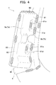
FIG. 4 is an enlarged perspective view of the bracket and its surrounding structure as viewed from the rear; -
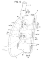
FIG. 5 is an enlarged perspective view of a bracket and its surrounding structure as viewed from the front; -
FIG. 6 is an enlarged perspective view of the bracket and its surrounding structure as viewed from the rear; -
FIG. 7 is a sectional view of the bracket; and -
FIG. 8 includes (a) a perspective view showing an embodiment having a stepped profile formed only on an upper wall, and (b) a perspective view showing an embodiment having a stepped profile formed continuously only on the upper wall and an outer wall. - Hereafter, a description will be given of one embodiment (first embodiment) of the present invention with reference to the drawings.
- A vehicle seat according to the present embodiment is made up of a
seat frame 1 as shown inFIG. 1 the outside of which is covered with a seat cushion made of urethane foam or the like. Theseat frame 1 includes a seat backframe 2 and aseat bottom frame 3. It is to be understood that in describing the present invention, the front/rear, left/right and upper/lower are defined as viewed from an occupant sitting on the seat. - The seat back
frame 2 is configured to include a pair of side frames 4, apipe frame 5 as one example of a reinforcing frame (inner frame) for reinforcing the side frames 4, alower frame 6, and abracket 7 as one example of a force-receiving member. - The side frames 4 are plate-like members which constitute left and right lower portions of the seat back
frame 2, and each configured to protrude frontward (in at least one of the front and rear directions) beyond thepipe frame 5, as shown inFIG. 2 . This configuration provides a frontwardly overhanging shape formed at each side of the seat back, and allows an air bag or other parts (not shown) to be securely fixed to the frontwardly and rearwardly extending plate-like side frames 4. - To be more specific, as shown in
FIG. 3(a) , eachside frame 4 has a throughhole 41 pierced through the left and right sides at an appropriate position thereof, and afront portion 42 thereof is bent inwardly to the left or to the right and further bent to the rear to form a U-shaped cross section. This configuration serves to improve the rigidity of thefront portion 42 of theside frame 4. - A
rear portion 43 of eachside frame 4 is bent inwardly to the left or to the right to form an L-shaped cross section, and is joined to thepipe frame 5 by welding. InFIG. 3(a) , welds or spots welded by a welding torch T are illustrated with exaggerated black dots. - As shown in
FIG. 1 , thepipe frame 5 is a reinforcing member for reinforcingside frames 4, having a cylindrical shape (with a closed section), which is bent into a shape of a substantially rectangular loop. Thispipe frame 5 includesside portions lower portion 51 connecting lower ends of theside portions upper portion 54 connecting upper ends of theside portions right side portions pipe frame 5 are joined to laterally inner sides of the side frames 4, respectively. With this configuration, the lower portion 51 (including portions extending obliquely downward from the portions adjacent to the side frames 4) of thepipe frame 5 is configured to serve, in combination with thelower frame 6, as a load transmission part, to transmit a load to the left or to the right. - Two wires W bent to ascend and descend several times are provided in positions spaced out vertically, and joined to left and
right side portions pipe frame 5, and a pressure-receiving member C shaped like a plate and made of plastic is fixed to these wires W. With this configuration, when the vehicle receives a rear-end collision load, the occupant subsides rearward together with the pressure-receiving member C inside thepipe frame 5, and thus the impact of the rear-end collision load against the occupant can be softened. - The
lower frame 6 is a plate-like member extending laterally, which is joined to the lower portions of the side frames 4 and to thelower portion 51 of thepipe frame 5. With this configuration, a load imposed on thebracket 7 from outside in the left or right direction is transmitted through thelower frame 6 and the aforementionedlower portion 51 of thepipe frame 5 to the side laterally opposite to that on which thebracket 7 is provided. - The
bracket 7 is a part provided discretely from thepipe frame 5 and the side frames 4, and disposed adjacent, and joined, to the left side (laterally outer side) of the left side frame 4 (one of the side frames). To be more specific, thebracket 7 is configured such that an input-side end portion 7a thereof located at a laterally outer side (outer wall 73 (seeFIG. 2 )) when the vehicle seat is installed in the vehicle is disposed near a side panel (another member) such as a side pillar or a door of the vehicle, so that a side collision load imposed on the vehicle from the input-side end portion 7a is received through the side panel. In thebracket 7, a load received from the input-side end portion 7a is outputted (transmitted) from an output-side end portion 7b located at a laterally inner side thereof to theside frame 4 and thepipe frame 5. - The
bracket 7 is, as shown inFIG. 2 , directly fixed by welding to thepipe frame 5 through two throughholes 41 as one example of an opening formed in theside frame 4. With this configuration, irrespective of the angle and magnitude of the side collision load received, the load can be transmitted properly from thebracket 7 to thepipe frame 5 without getting affected by deformation of theside frame 4. In the drawings, the welded spots are illustrated with shades of dots. - To be more specific, the
bracket 7 is segmented in front and rear halves of a front-side box-like member 8 and a rear-side box-like member 9 which are fitted together, and configured such that the box-like members - The front-side box-
like member 8 includes a plate-likefront wall 81 elongated in the upward-and-downward direction longer than extending in the lateral direction, anupper wall 82 extending from an upper end of thefront wall 81 rearward, anouter wall 83 extending from a laterally outer end of thefront wall 81 rearward, and alower wall 84 extending from a lower end of thefront wall 81 rearward, all of which are provided integrally. In other words, the front-side box-like member 8 is configured to have a shape of a box which opens to the rear and to a laterally inner side. - In the
front wall 81, two recessedportions 81a (providing an uneven shape) disposed in a portion separate from upper and lower ends of thefront wall 81 and configured to be recessed inwardly in the front-rear direction are arranged in positions spaced out vertically at a predetermined distance. With this configuration, the rigidity of thefront wall 81 is enhanced, and thus a side collision load can be transmitted effectively to thepipe frame 5 by the high-rigidity front wall 81. Moreover, since the recessedportions 81a are formed in the portion of thefront wall 81 separate from the upper and lower ends thereof, the upper and lower end corners of thefront wall 81 can be formed continuously in the left-right direction, so that the continuous corners can effectively transmit the load from outside to inside in the lateral direction. - Each recessed
portion 81a is formed at a laterally inner end portion (output-side end portion) 8b of thefront wall 81, and thus opens to the front and to the laterally inner side. With this configuration, anedge 81c of the output-side end portion 8b is bent to the front and to the rear, and thus the rigidity of theedge 81c located at an output side of the side collision load can be increased, so that the side collision load can effectively be transmitted to thepipe frame 5 or the like. - As shown in
FIG. 3(a) , each recessedportion 81a (seeFIG. 2 ) has abottom wall 81d and a leftinner wall 81 g extending in an obliquely rightward-and-rearward direction from the front side of the input-side end portion 8a of thefront wall 81 toward thebottom wall 81d of the recessedportion 81 a. In other words, thefront wall 81 has an oblique surface (inner wall 8 1 g) angled relative to the lateral direction such that a width in the front-rear direction of thebracket 7 is gradually made smaller toward a left-to-right direction. With this feature, concentration of a stress, as imparted upon receipt of a load, on a part of thefront wall 81 is suppressed, and thus deformation of thebracket 7 can be suppressed, so that the load can be transmitted properly. - At the
bottom wall 81d of each recessedportion 81a, anextension portion 81e (part of the force-receiving member provided at a laterally inner side thereof) extending laterally inward beyond theedge 81c of thefront wall 81 is formed. Thisextension portion 81e is disposed inside the throughhole 41 of theside frame 4 described above, and extends to thepipe frame 5, so that theextension portion 81e abutting on thepipe frame 5 is welded to thepipe frame 5. - Since only the
extension portion 81e is passed through the throughhole 41, the throughhole 41 may be sized to conform to theextension portion 81e, and thus the throughhole 41 may be made smaller so that the rigidity of theside frame 4 can be enhanced. To be more specific, in the present embodiment, the throughhole 41 is shaped like an elongate hole having dimensions smaller than the width of thepipe frame 5 in a front-rear direction, and smaller than the whole length of theedge 81c of thefront wall 81 and greater than theextension portion 81e in a vertical direction. - The size of the through
hole 41 may be designed to have, at the largest, an area comparable or smaller than a cross-sectional area of a laterally inner end portion (adjacent an end located at a side from which the side collision load is outputted) of thebracket 7. The throughhole 41 formed to have a size described above makes it possible to impart a higher rigidity of theside frame 4, for example, in comparison with a through hole formed in the side frame to have such a size as to allow the laterally inner end portion of thebracket 7 to be passed through in its entirety. - Although the
extension portion 81e is provided in the present embodiment, the present invention is not limited to this configuration; i.e., a configuration without theextension portion 81e may also be possible. In this configuration, some gap may be left between thepipe frame 5 and theedge 81c of thefront wall 81, but this gap still permits welding by which thepipe frame 5 and the bracket can be joined directly. - As shown in
FIGS. 2 ,3(a) , a portion (including theextension portion 81e) of theedge 8 1 c of the output-side end portion 8b which defines the edge of thebottom wall 8 1 d of the recessedportion 81 a is located within the width in the front-rear direction of thepipe frame 5. Of this portion, theextension portion 81e is fixed to a central portion 5a located at a center in the front-rear direction of thepipe frame 5. With this configuration, the load from thebracket 7 is transmitted intensively to the central portion 5a of thepipe frame 5, and thus the load can be transmitted more effectively. - A
center 5b in the front-rear direction of thepipe frame 5 is located within a width in the front-rear direction of thebracket 7. With this configuration, upon side collision, the load can be transmitted more effectively because thebracket 7 can be prevented from slipping out to the front or to the rear on a cylindrical outer surface of thepipe frame 5. - As shown in
FIG. 2 , an upper portion and a lower portion of theedge 81c of thefront wall 81 are fixed to theside frame 4 by welding. In other words, thefront wall 81 is fixed directly to both of theside frame 4 and thepipe frame 5. With this configuration, the load received by thebracket 7 is transmitted not only through thepipe frame 5 but also through theside frame 4 to the load transmission part (thelower frame 6 and thelower portion 51 of the pipe frame 5), and thus more effective transmission of the load can be ensured. It is appreciated that the load transmitted to the load transmission part can be transmitted to the vehicle body side through a console box or the like provided at a side opposite to that on which thebracket 7 is provided. - As shown in
FIG. 4 , the rear-side box-like member 9 includes a plate-likerear wall 91 elongated in the upward-and-downward direction longer than extending in the lateral direction, anupper wall 92 extending from an upper end of therear wall 91 frontward, anouter wall 93 extending from a laterally outer end of therear wall 91 frontward, and alower wall 94 extending from a lower end of therear wall 91 frontward, all of which are provided integrally. In short, the rear-side box-like member 9 is configured to have a shape of a box which opens to the front and to the laterally inner side. - In the
rear wall 91, two recessedportions 91a (providing an uneven shape) disposed in a portion separate from upper and lower ends of therear wall 91 and configured to be recessed inwardly in the front-rear direction are arranged in positions spaced out vertically at a predetermined distance. With this configuration, the rigidity of therear wall 91 is enhanced, and thus a side collision load can be transmitted effectively to the laterally inner side by the high-rigidityrear wall 91. Moreover, since the recessedportions 91a are formed in the portion of therear wall 91 separate from the upper and lower ends thereof, the front and rear end corners of therear wall 91 can be formed continuously in the left-right direction, so that the continuous corners can effectively transmit the load from outside to inside in the lateral direction. - As shown in
FIG. 3(a) , each recessedportion 91 a has abottom wall 91d and a leftinner wall 91g extending in an obliquely rightward-and-frontward direction from the rear side of the input-side end portion 9a of therear wall 91 toward thebottom wall 91d. In other words, therear wall 91 has an oblique surface (inner wall 91g) angled relative to the lateral direction such that a width in the front-rear direction of thebracket 7 is gradually made smaller toward a left-to-right direction. With this feature, concentration of a stress, as imparted upon receipt of a load, on a part of therear wall 91 is suppressed, and thus deformation of thebracket 7 can be suppressed, so that the load can be received reliably. Moreover, the load can be transmitted properly. - Each recessed
portion 91a is disposed opposite to a corresponding recessedportion 8 1 a of the front-side box-like member 8 in the front-rear direction, whereas eachbottom wall 91 d and abottom wall 81d of a corresponding recessedportion 81a are disposed to adjoin to each other, as shown inFIG. 3(a) . With this configuration, the twobottom walls bracket 7, and thus effective transmission of the side collision load can be achieved. - The two
bottom walls 8 1 d, 91 d adjoining to each other are joined together by welding. With this configuration, the rigidity of thebracket 7 can be enhanced, and thus effective transmission of the side collision load can be achieved. - The two
bottom walls pipe frame 5. With this feature, the side collision load can be effectively transmitted to thepipe frame 5 through the thick portion made up of the adjoiningbottom walls - Furthermore, the
center 5b in the front-rear direction of thepipe frame 5 is located within a width in the front-rear direction of the thick portion made up of the adjoiningbottom walls center 5b or therearound of thepipe frame 5 through the thick portion made up of the adjoiningbottom walls - An
edge 91c of the output-side end portion 9b in an upper portion (extending from the lower recessedportion 91 a above) of therear wall 91 is located within the width in the front-rear direction of thepipe frame 5. With this configuration, the output-side end portion 9b, specifically theedge 91c and theedge 81c (defining the edge of thebottom wall 81d) of thefront wall 81 is located within the width of the pipe frame 5 (reinforcing frame) in the front-rear direction. As a result, the load received is transmitted intensively to thepipe frame 5, and thus the load can be transmitted properly. - As shown in
FIG. 4 , a laterally inner end portion (output-side end portion) 9b of therear wall 91 is fixed to theside frame 4 by welding. To be more specific, as shown inFIG. 3(a) , the output-side end portion 9b, located laterally inner end of therear wall 91 is joined to a closed-section-shaped portion made up of arear portion 43, bent into an L-shape, of theside frame 4 and a left-side rear portion of thepipe frame 5. With this configuration, the side collision load transmitted from therear wall 91 to a laterally inner side is received properly by the closed-section-shaped portion, and thus can be transmitted effectively to thepipe frame 5. - Furthermore, as shown in
FIGS. 2 ,3 , theupper wall 92,outer wall 93 andlower wall 94 of the rear-side box-like member 9 is disposed over theupper wall 82,outer wall 83 andlower wall 84 of the front-side box-like member 8, and fixed to the walls 82-84, respectively by welding. - With this configuration, as shown in
FIG. 3(b) , theupper wall 72 of thebracket 7 has a steppedprofile 72a (providing an uneven shape) formed, at a position separate from the front and rear ends thereof, by overlapping theupper walls 82, 92 (two plate-like portions) of the respective box-like members upper wall 72 substantially at the center thereof in the front-rear direction is formed as a thick portion by overlapping theupper walls upper wall 72 can be enhanced, so that a side collision load can be transmitted effectively. - Furthermore, since the stepped
profile 72a (providing an uneven shape) is formed in a position separate from the front and rear ends of theupper wall 72, the front and rear end corners of theupper wall 72 can be formed continuously in the left-right direction, so that the continuous corners can effectively transmit the load from outside to inside in the lateral direction. - Similarly, as shown in
FIGS. 3(a), (c) , theouter wall 73 andlower wall 74 of thebracket 7 also have steppedprofiles outer walls lower walls like members outer wall 73 and thelower wall 74 as well can be enhanced, and the front and rear end corners of thelower wall 74 can be formed continuously in the left-right direction, so that the continuous corners can effectively transmit the load from outside to inside in the lateral direction. - The stepped
profiles upper wall 72,outer wall 73 andlower wall 74 of thebracket 7 as a result of fitting the rear-side box-like member 9 on the front-side box-like member 8. With this configuration, the thick portion of theouter wall 73 is formed continuously to the thick portions of theupper wall 72 and thelower wall 74, and thus a side collision load received by the thick portion of theouter wall 73 can be transmitted effectively to the laterally inner side through the upper and lower continuous thick portions. - Advantageous effects of the vehicle seat according to the present embodiment as described above are summarized hereinafter.
- Since the
bracket 7 is not fixed through theside frame 4 but fixed directly to thepipe frame 5, the side collision load received, irrespective of its angle and magnitude, can be transmitted properly from thebracket 7 to thepipe frame 5 without getting affected by deformation of theside frame 4. - Since the
bracket 7 is provided discretely from thepipe frame 5, each member can be formed into any shape freely, and can be made easy to assemble. - Since the
bracket 7 and thepipe frame 5 are fixed together through an opening (through hole 41) formed in theside frame 4, the need, for example, to divide theside frame 4 into front and rear parts or upper and lower parts so as to detour around a position in which the bracket and the pipe frame are fixed together can be obviated, and thus the rigidity of theside frame 4 can be enhanced. - Since only part (
extension portion 81 e) of thebracket 7 is fixed to thepipe frame 5 through the opening (through hole 41), the need to form an opening allowing an entire side portion at a laterally inner side of the bracket to pass therethrough in the side frame can be obviated, and thus the rigidity of theside frame 4 can be further enhanced. - Since the opening formed in the
side frame 4 is configured as a throughhole 41, the rigidity of theside frame 4 can be further enhanced, in comparison with a configuration in which the opening is shaped as a groove (or a hollow) that opens to the front or to the rear, because an upper portion and a lower portion of theside frame 4 above and below the position in which thebracket 7 and thepipe frame 5 are fixed together can be connected at the front and rear sides of that position. - Since the
bracket 7 is fixed to a portion of thepipe frame 5 having a shape with a closed section, the load received by thebracket 7 can be transmitted properly to the load transmission part (thelower frame 6 and thelower portion 51 of the pipe frame 5) through thepipe frame 5 which can be resistant to deformation. - Since the
bracket 7 is fixed directly to the both of theside frame 4 and thepipe frame 5, the load received by thebracket 7 is transmitted not only through thepipe frame 5 but also through theside frame 4 to the load transmission part, so that the load can be transmitted more effectively. - Since the
center 5b of the pipe frame is located within the width in the front-rear direction of thebracket 7, thebracket 7 upon receipt of side collision load can be prevented from slipping out to the front or to the rear on a cylindrical outer surface of thepipe frame 5, so that the load can be transmitted more effectively. - Since the
bracket 7 is fixed to the portion 5a located at a center in the front-rear direction of thepipe frame 5, the load from thebracket 7 can be transmitted intensively to the central portion 5a at the center in the front-rear direction of thepipe frame 5, so that the load can be transmitted more effectively. - Since the output-
side end portion 7b of thebracket 7 is located within the width in the front-rear direction of thepipe frame 5, the load received can be concentrated on thepipe frame 5, so that the load received by thebracket 7 can be transmitted effectively to thepipe frame 5. - Since the
front wall 81 and therear wall 91 of thebracket 7 include oblique surfaces (inner walls bracket 7 is gradually made smaller, deformation of thebracket 7 can be suppressed, and thus the load can be transmitted more effectively. - Since a portion of the
front wall 81 and therear wall 91 of thebracket 7 separate from their upper and lower ends is configured to provide an uneven shape (recessedportions walls bracket 7 is thin, thewalls bracket 7 to be made thinner in wall thickness, and the vehicle seat to be made lighter in weight. - Since the uneven shape is not provided at the upper and lower ends of the
front wall 81 and therear wall 91, the upper and lower end corners of thefront wall 81 and therear wall 91 can be formed continuously in the lateral direction; therefore, these continuous corners serve to transmit a load effectively from outside to inside in the lateral direction. - Since the
edge 81c at the laterally inner side of thefront wall 81 which is the side from which a side collision load is outputted is bent frontward and rearward, the rigidity of thisedge 81c is enhanced, so that the side collision load can be effectively outputted. - Since the recessed
portions front wall 81 and therear wall 91 whereas a thicker portion formed by thebottom walls 8 1 d, 9 1 d adjoining to each other is disposed within the width in the front-rear direction of thebracket 7, the rigidity of thefront wall 81 and therear wall 91 of thebracket 7 and the rigidity of the inside of thebracket 7 can be enhanced, so that a load can be transmitted more effectively. - Since the
bottom walls pipe frame 5, a load transmitted to eachbottom wall pipe frame 5. - Since the
center 5b of thepipe frame 5 is located within the total width in the front-rear direction of the adjoiningbottom walls bottom wall 8 1 d, 91 d can be transmitted intensively to and around the center of thepipe frame 5. - Since a portion of the
upper wall 72 and thelower wall 74 of thebracket 7 separate from their front and rear ends is configured to provide an uneven shape (steppedprofiles walls bracket 7 is thin, thewalls bracket 7 to be made thinner in wall thickness, and the vehicle seat to be made lighter in weight. - Since the uneven shape is not provided at the front and rear ends of the
upper wall 72 and thelower wall 74, the front and rear end corners of theupper wall 72 and thelower wall 74 can be formed continuously in the lateral direction; therefore, these continuous corners serve to transmit a load effectively from outside to inside in the lateral direction. - Since the uneven shape is made of the stepped profile (stepped
profile 72a) provided by overlapping two walls (e.g.,upper walls 82, 92), the overlapped portion of the two walls is rendered thicker, so that the rigidity can be enhanced. - Since the stepped
profiles outer wall 73 extends continuously to theupper wall 72 and thelower wall 74, a load received at theouter wall 73 can be transmitted effectively through theupper wall 72 and thelower wall 74 in a laterally inward direction. - Hereinafter, a description will be given of another embodiment (second embodiment) of the present invention with reference made mainly to
FIGS. 5-7 . In the drawings which will be referred to in describing the second embodiment, substantially the same elements as those described in the first embodiment will be designated by the same reference numerals, and an explanation thereof will be omitted. - A vehicle seat according to the present embodiment is, as in the first embodiment, made up of a
seat frame 1 the outside of which is covered with a seat cushion made of urethane foam or the like. Theseat frame 1 includes a seat backframe 2 and aseat bottom frame 3, and the seat backframe 2 is configured to include a pair of side frames 4, a reinforcing frame for reinforcing the side frames 4, that is, apipe frame 5, alower frame 6, and abracket 7 as one example of a force-receiving member (seeFIG. 1 ). - The
bracket 7 is, as in the first embodiment, configured such that a laterally outer input-side end portion 7a (outer wall 73 (seeFIG. 5 )) is disposed near a side panel (another member) such as a side pillar or a door of the vehicle when the vehicle seat is installed in the vehicle and that a side collision load imposed on the vehicle is received, through the side panel, from this input-side end portion 7a. Moreover, thebracket 7 is configured such that a load received from the input-side end portion 7a is outputted (transmitted) from a laterally inner output-side end portion 7b to theside frame 4 and thepipe frame 5. - As shown in
FIG. 6 , therear wall 91 has alower end portion 91f formed to bulge rearward in a substantially ridge-like shape. With this configuration, thebracket 7 is made to have a width D1 in a front-rear direction of its lower end portion greater than a width D2 in the front-rear direction of its upper end portion. As a result, a sufficient area for receiving the load is provided, and the rigidity of the lower end portion, in which load transmission occurs principally, of thebracket 7 is increased, and thus the load can be received reliably. Moreover, the load can thus be transmitted effectively. - As shown in
FIGS. 5 ,6 , each box-like member 8, 9 (bracket 7) is configured such that the input-side end portion 7a (8a and 9a) stretches out in upward and downward directions wider than the output-side end portion 7b (8b and 9b). To be more specific, as shown inFIG. 7 , thebracket 7 has a shape with a closed cross section, and left-side portions (on the laterally outer sides) of theupper wall 72 and thelower wall 74 bulge out upward or downward. - With this configuration, the bulged portions of the
bracket 7, that is, an upper end portion (bulge 75) and a lower end portion (bulge 76) of the input-side end portion 7a have a double-wall structure in the lateral direction that is a direction in which a load is received. As a result, the rigidity of thebracket 7 can be enhanced, and thus deformation of thebracket 7 can be suppressed, so that the load can be received from the side panel or the like by thebracket 7 reliably. Moreover, the load can thus be transmitted effectively. Furthermore, a wider area of the input-side end portion 7a (outer wall 73) provided by thebulges - Right-side (laterally inner side)
walls upper wall 72 and lower wall 74) of thebulges bulges bracket 7 is gradually made smaller toward theside frame 4. With this configuration, concentration of a stress (as imparted upon receipt of a load) on a part of theupper wall 72 or thelower wall 74 is suppressed, and thus deformation of thebracket 7 can be suppressed, so that the load can be received reliably. Moreover, the load can thus be transmitted properly. - Advantageous effects of the vehicle seat according to the present embodiment as described above are summarized hereinafter.
- Since the
bracket 7 has a shape with a closed section and the input-side end portion 7a stretches out in upward and downward directions wider than the output-side end portion 7b, the rigidity of thebracket 7 can be increased. Accordingly, deformation of thebracket 7 can be suppressed, and thus the load from the side panel or the like can be received reliably by thebracket 7. Moreover, the load can be transmitted properly from thebracket 7 to thepipe frame 5 and thelower frame 6. - Since the width D1 in the front-rear direction of the lower end portion of the input-
side end portion 7a is greater than the width D2 in the front-rear direction of the upper end portion of the input-side end portion 7a, it is ensured that a sufficient area for receiving the load is provided, and thus the load can be received more reliably by thebracket 7, and the load can be transmitted more effectively. In particular, since the transmission of the load in the present embodiment occurs at a lower position through the load transmission part (thelower frame 6 and thelower portion 51 of the pipe frame 5), the greater width D1 in the front-rear direction of the input-side end portion 7a contributes to improved transmission of the load. - Since the
upper wall 72 and thelower wall 74 of thebracket 7 include oblique surfaces (walls bracket 7 is gradually made smaller, deformation of thebracket 7 can be suppressed, and thus the load can be received more reliably. Moreover, the load can thus be transmitted more effectively. - Since the
bracket 7 is not fixed through theside frame 4 but fixed directly to thepipe frame 5, the side collision load received, irrespective of its angle and magnitude, can be transmitted properly from thebracket 7 to thepipe frame 5 without getting affected by deformation of theside frame 4. - Since the
bracket 7 is provided discretely from thepipe frame 5, each member can be formed into any shape freely, and can be made easy to assemble. - Since the
bracket 7 and thepipe frame 5 are fixed together through an opening (through hole 41) formed in theside frame 4, the need, for example, to divide the side frame into front and rear parts or upper and lower parts so as to detour around a position in which the bracket and the pipe frame are fixed together can be obviated, and thus the rigidity of theside frame 4 can be enhanced. - Since only part (
extension portion 81e) of thebracket 7 is fixed to thepipe frame 5 through the opening (through hole 41), the need to form an opening allowing an entire side portion at a laterally inner side of the bracket to pass therethrough in the side frame can be obviated, and thus the rigidity of theside frame 4 can be further enhanced. - Since the opening formed in the
side frame 4 is configured as a throughhole 41, the rigidity of theside frame 4 can be further enhanced, in comparison with a configuration in which the opening is shaped as a groove (or a hollow) that opens to the front or to the rear, because an upper portion and a lower portion of theside frame 4 above and below the position in which thebracket 7 and thepipe frame 5 are fixed together can be connected at the front and rear sides of that position. - Since the
bracket 7 is fixed to a portion of thepipe frame 5 having a shape with a closed section, the load received by thebracket 7 can be transmitted properly to the load transmission part (thelower frame 6 and thelower portion 51 of the pipe frame 5) through thepipe frame 5 which can be resistant to deformation. - Since the
bracket 7 is fixed directly to the both of theside frame 4 and thepipe frame 5, the load received by thebracket 7 is transmitted not only through thepipe frame 5 but also through theside frame 4 to the load transmission part, and thus, the load can be transmitted more effectively. - Since the
center 5b of thepipe frame 5 is located within the width in the front-rear direction of thebracket 7, thebracket 7 upon receipt of side collision load can be prevented from slipping out to the front or to the rear on a cylindrical outer surface of thepipe frame 5, and thus, the load can be transmitted more effectively. - Since the
bracket 7 is fixed to the portion 5a located at a center in the front-rear direction of thepipe frame 5, the load from thebracket 7 can be transmitted intensively to the central portion 5a at the center in the front-rear direction of thepipe frame 5, and thus, the load can be transmitted more effectively. - Although the embodiments of the present invention have been described above, the present invention may be carried out into practice in appropriately modified configurations, as in the other embodiments described below.
- In the above-described embodiments, a
cylindrical pipe frame 5 is adopted as an inner frame (reinforcing frame), but the present invention is not limited to this configuration; for example, a pipe frame having a polygonal cross section, a solid cylindrical member, or a solid prismatic member may be usable. - In the above-described embodiments, the force-receiving member is embodied in the
bracket 7 composed of two box-like members - In the above-described embodiments, the load transmission part is configured as an assembly of the
lower frame 6 and thelower portion 51 of thepipe frame 5, but the present invention is not limited to this configuration. For example, in the above-described embodiments, thepipe frame 5 as the inner frame (reinforcing frame) is formed integrally with the load transmission part (lower portion 51), but if the pipe frame is configured to includeside portions upper portion 54, and is shaped like a letter U which opens toward downward, a separate frame connecting the lower end portions of the pipe frame may be provided as a load transmission part. Alternatively, if thelower portion 51 of thepipe frame 5 in the above-described embodiment is severed, with its midsection cut off, in two portions joined to thelower frame 6, thelower portions 51 extending halfway and thelower frame 6 may be configured as a load transmission part. - In the above-described embodiments, the
bracket 7 and thepipe frame 5 are fixed together by welding, but the present invention is not limited to this configuration; for example, a bolt may be applied for fixing these members together. - In the above-described embodiments, the through
hole 41 is configured to serve as an opening, but the present invention is not limited to this configuration; for example, the opening may be a hollow which opens to the front or to the rear. - In the above-described embodiments, part of the bracket 7 (i.e.,
extension portions 81e) is passed through the opening (through holes 41), but the present invention is not limited to this configuration; part of the inner frame (reinforcing frame) may be passed through the opening and fixed directly to the bracket. - In the above-described embodiments, the reinforcing frame (pipe frame 5) is configured to have a shape with a closed section in its entirety, but the present invention is not limited to this configuration; it may be advantageous only if at least a portion of the reinforcing frame to which the force-receiving member is fixed has a shape with a closed section.
- In the above-described embodiments, the force-receiving member is configured as a member for receiving a side collision load of a vehicle; however, the present invention is not limited to this configuration, but applicable, for example, to a member for receiving a load from an occupant, such as an arm rest attachment member, or to a member for receiving a load from an air bag upon activation of the air bag, such as an air bag attachment member. Furthermore, for example, a member for receiving a self weight (load) of a motor or the like, such as an attachment member for attaching a motor or the like having a heavy weight, may also be configured as such.
- In the above-described embodiments, the force-receiving member is provided at an outer side of the side frame, but the present invention is not limited to this configuration. For example, in a modified embodiment such that a plate-like side frame is further provided at a laterally inner side of the reinforcing frame (pipe frame 5) of the above-described embodiments, an arm rest attachment member or the like as described above may be disposed at a laterally inner side of the side frame, and the arm rest attachment member or the like may be directly fixed to the reinforcing frame.
- In the above-described embodiments, the recessed
portions - In the above-described embodiments, the recessed
portions front wall 81 and therear wall 91, but the present invention is not limited to this configuration; alternatively, the uneven shape may be provided at least one of the front and rear walls. - In the above-described embodiments, the recessed
portion 81 a of thefront wall 81 is formed at a laterally inner end of thefront wall 81 to open to a laterally inner side, but the present invention is not limited to this configuration; alternatively, a recessed portion of a rear wall may be formed at a laterally inner end of the rear wall to open to a laterally inner side. - The recessed portion may be formed at a laterally outer end of a front wall or a rear wall, not to open to a laterally inner side but to open to a laterally outer side. With this configuration, an edge of the force-receiving member at a side from which a side collision load is received can be configured to be bent frontward and rearward, so that the side collision load can be received adequately by the force-receiving member.
- The recessed portion may be provided in both of the laterally inner and outer sides. With this configuration, edges of the force-receiving member at both sides from which a side collision load is received and outputted, respectively, can be configured to be bent frontward and rearward, so that the side collision load can be received and outputted adequately.
- In the above-described embodiments, the stepped
profiles FIG. 8(a) , a steppedprofile 711a may be provided only at anupper wall 711 of abracket 710. In this configuration, as well, the rigidity of theupper wall 711 can be enhanced so that a load can be transmitted effectively. - Moreover, the stepped profile provided continuously from at least one of the upper wall and the lower wall to the outer wall may suffice. That is, for example, as shown in
FIG. 8(b) , steppedprofiles upper wall 721 to anouter wall 722 of abracket 720. In this configuration, as well, since the thicker portion of theouter wall 722 extends continuously to theupper wall 721, a load can be transmitted effectively from theouter wall 722 to theupper wall 721. - In the above-described embodiments, the stepped
profile 72a is adopted as an uneven shape, but the present invention is not limited to this configuration; for example, a recess or a protrusion may be adopted. - In the above-described second embodiment, the
front wall 81 and therear wall 91 have oblique surfaces (inner walls bracket 7 is gradually made smaller, but the present invention is not limited to this configuration. For example, an alternative configuration such that only either one of thefront wall 81 or therear wall 91 has such an oblique surface, or another configuration in which neither of them has such an oblique surface may be feasible. - Similarly, in the above-described second embodiment, the
upper wall 72 and thelower wall 74 have oblique surfaces (walls bracket 7 is gradually made smaller, but the present invention is not limited to this configuration. For example, an alternative configuration such that only either one of theupper wall 72 or thelower wall 74 has such an oblique surface, or another configuration in which neither of them has such an oblique surface. - In the above-described second embodiment, the output-
side end portion 8b of thefront wall 81 is configured such that only part (portion which defines an edge of thebottom wall 81d) of theedge 81c is located within the width of thepipe frame 5 in the front-rear direction, but the present invention is not limited to this configuration; for example, the entire edge of the output-side end portion may be located within the width of thepipe frame 5. - In the above-described second embodiment, the bracket 7 (the input-
side end portion 7a and the output-side end portion 7b) is configured such that the width D1 in the front-rear direction of its lower portion is greater than the width D2 in the front-rear direction of its upper portion, but the present invention is not limited to this configuration; for example, the width in the front-rear direction of the lower portion of the force-receiving member and the width in the front-rear direction of the upper portion of the force-receiving member may be equal to each other. An alternative configuration in which only the input-side end portion is configured to have a width in the front-rear direction of its lower portion greater than a width in the front-rear direction of its upper portion. - In the above-described second embodiment, the bracket 7 (force-receiving member) is configured such that its input-
side end portion 7a stretches out in the upward and downward directions wider than its output-side end portion 7b, but the present invention is not limited to this configuration; for example, the force-receiving member may be configured such that its input-side end potion stretches out in the frontward and/or rearward directions wider than its output-side end portion. Alternatively, the force-receiving member may be configured such that its input-side end portion stretches out in the upward, downward, frontward and rearward directions wider than its output-side end portion.
Claims (22)
- A vehicle seat comprising:left and right side frames which constitute left and right portions of a seat back frame;a reinforcing frame disposed adjacent to one side frame in a lateral direction, and configured to reinforce the side frame; anda force-receiving member disposed adjacent to the one side frame, provided discretely from the reinforcing frame, and configured to receive a load from another member,wherein the force-receiving member is disposed opposite to the reinforcing frame with the side frame disposed therebetween, and directly fixed to the reinforcing frame.
- The vehicle seat according to claim 1, wherein the force-receiving member and the reinforcing frame are fixed together through an opening formed in the side frame.
- The vehicle seat according to claim 2, wherein the force-receiving member includes an extension portion provided at a laterally inner side of the force-receiving member and extending through the opening to the reinforcing frame, the extension portion being fixed to the reinforcing frame.
- The vehicle seat according to claim 2, wherein the opening is a through hole.
- The vehicle seat according to claim 1, wherein at least a portion of the reinforcing frame to which the force-receiving member is fixed has a shape with a closed section.
- The vehicle seat according to claim 1, wherein the force-receiving member is fixed directly to both of the side frame and the reinforcing frame.
- The vehicle seat according to claim 1, wherein a center in a front-rear direction of the reinforcing frame is located within a width in the front-rear direction of the force-receiving member.
- The vehicle seat according to claim 1, wherein the force-receiving member is fixed to a portion of the reinforcing frame at a center in a front-rear direction of the reinforcing frame.
- The vehicle seat according to claim 1, wherein the force-receiving member includes a front wall and a rear wall and has a shape with a closed cross section, and a portion of at least one of the front wall and the rear wall separate from upper and lower ends thereof provides an uneven shape.
- The vehicle seat according to claim 9, wherein the uneven shape is formed in at least one of a laterally outer end and a laterally inner end of the at least one of the front wall and the rear wall, whereby an edge of the one end is bent frontward and rearward.
- The vehicle seat according to claim 9, wherein the uneven shape is formed in both of the front wall and the rear wall, as recessed portions that are recessed inwardly in a front-rear direction; and
wherein bottom walls of the respective recessed portions adjoin to each other. - The vehicle seat according to claim 11, wherein each of the bottom walls is located within a width in the front-rear direction of the reinforcing frame.
- The vehicle seat according to claim 12, wherein a center in the front-rear direction of the reinforcing frame is located within a total width in the front-rear direction of the adjoined bottom walls.
- The vehicle seat according to claim 1, wherein the force-receiving member has a shape with a closed cross section, and has an input-side end portion and an output-side end portion, such that the input-side end portion stretches out in at least one of upward, downward, frontward and rearward directions wider than the output-side end portion.
- The vehicle seat according to claim 14, wherein the input-side end portion has a lower end portion and an upper end portion such that a width in a front-rear direction of the lower end portion is greater than that of the upper end portion.
- The vehicle seat according to claim 14, wherein the reinforcing frame is shaped like a pipe, and
the output-side end portion of the force-receiving member is located within a width in a front-rear direction of the reinforcing frame. - The vehicle seat according to claim 14, wherein the force-receiving member includes front and rear walls of which at least a portion has an oblique surface angled relative to a lateral direction such that a width in a front-rear direction of the force-receiving member is gradually made smaller.
- The vehicle seat according to claim 14, wherein the force-receiving member includes upper and lower walls of which at least a portion has an oblique surface angled relative to a lateral direction such that a width in an upward-and-downward direction of the force-receiving member is gradually made smaller.
- The vehicle seat according to claim 1 or claim 9 wherein the force-receiving member includes an upper wall and a lower wall and has a shape with a closed cross section, and a portion of at least one of the upper wall and the lower wall separate from front and rear ends thereof provides an uneven shape.
- The vehicle seat according claim 19, wherein the uneven shape formed in the at least one of the upper wall and the lower wall is of a stepped profile formed by overlapping two plate-like portions.
- The vehicle seat according to claim 20, wherein the stepped profile is continuously formed from the at least one of the upper wall and the lower wall to an outer wall of the force-receiving member located at a side laterally opposite to that on which the reinforcing frame is provided.
- The vehicle seat according to claim 21, wherein the force-receiving member is segmented in front and rear halves of box-like members which are fitted together, and
the stepped profile is formed as a result of fitting the box-like members together, continuously across the upper wall, the outer wall and the lower wall.
Applications Claiming Priority (5)
| Application Number | Priority Date | Filing Date | Title |
|---|---|---|---|
| JP2010157272A JP5563393B2 (en) | 2010-07-09 | 2010-07-09 | Vehicle seat |
| JP2010157279A JP5572463B2 (en) | 2010-07-09 | 2010-07-09 | Vehicle seat |
| JP2010157273A JP5572461B2 (en) | 2010-07-09 | 2010-07-09 | Vehicle seat |
| JP2010157276A JP5572462B2 (en) | 2010-07-09 | 2010-07-09 | Vehicle seat |
| PCT/JP2011/065491 WO2012005298A1 (en) | 2010-07-09 | 2011-07-06 | Vehicle seat |
Publications (2)
| Publication Number | Publication Date |
|---|---|
| EP2599662A1 true EP2599662A1 (en) | 2013-06-05 |
| EP2599662A4 EP2599662A4 (en) | 2016-04-27 |
Family
ID=45441275
Family Applications (1)
| Application Number | Title | Priority Date | Filing Date |
|---|---|---|---|
| EP11803632.6A Withdrawn EP2599662A4 (en) | 2010-07-09 | 2011-07-06 | Vehicle seat |
Country Status (4)
| Country | Link |
|---|---|
| US (2) | US9108547B2 (en) |
| EP (1) | EP2599662A4 (en) |
| CN (1) | CN102985289B (en) |
| WO (1) | WO2012005298A1 (en) |
Families Citing this family (10)
| Publication number | Priority date | Publication date | Assignee | Title |
|---|---|---|---|---|
| JP5805637B2 (en) | 2010-07-09 | 2015-11-04 | テイ・エス テック株式会社 | Vehicle seat |
| CN102985288A (en) | 2010-07-09 | 2013-03-20 | 提爱思科技股份有限公司 | Vehicle seat |
| WO2012005283A1 (en) | 2010-07-09 | 2012-01-12 | テイ・エス テック株式会社 | Vehicle seat |
| US20150291072A1 (en) * | 2012-11-16 | 2015-10-15 | Ts Tech Co., Ltd. | Vehicle seat |
| JP6001004B2 (en) * | 2014-04-25 | 2016-10-05 | トヨタ紡織株式会社 | Vehicle seat |
| FR3063429A1 (en) * | 2017-03-06 | 2018-09-07 | Newtl | ARRANGEMENT FOR A WHEELCHAIR USER LOCATION |
| CN110461646B (en) | 2017-03-27 | 2022-04-19 | 提爱思科技股份有限公司 | Seat for vehicle |
| JP2018192934A (en) * | 2017-05-18 | 2018-12-06 | トヨタ紡織株式会社 | Back frame of seat for vehicle |
| US11279488B2 (en) * | 2020-02-20 | 2022-03-22 | B/E Aerospace, Inc. | Seat assembly with sacrificial backrest breakover feature |
| CN115384372A (en) * | 2021-05-25 | 2022-11-25 | 上海汽车集团股份有限公司 | Seat frame, manufacturing method of seat frame, and seat assembly |
Family Cites Families (25)
| Publication number | Priority date | Publication date | Assignee | Title |
|---|---|---|---|---|
| JPH057956Y2 (en) * | 1987-11-27 | 1993-03-01 | ||
| US5407244A (en) * | 1992-04-24 | 1995-04-18 | Ikeda Bussan Co., Ltd. | Safety seat and safety arrangement of seats |
| GB2283163A (en) | 1993-10-26 | 1995-05-03 | Autoliv Dev | "Improvements in or relating to a vehicle seat" |
| JP3583556B2 (en) | 1996-08-06 | 2004-11-04 | ジョンソン コントロールズ オートモーティブ システムズ株式会社 | Car seats |
| JP2952822B2 (en) | 1998-02-10 | 1999-09-27 | 本田技研工業株式会社 | Side collision protection device for vehicles |
| JP2000103275A (en) | 1998-09-30 | 2000-04-11 | Fuji Heavy Ind Ltd | Car seat |
| EP0990553B1 (en) * | 1998-09-30 | 2006-03-08 | Fuji Jukogyo Kabushiki Kaisha | Vehicle seat with occupant protection devices |
| JP3852252B2 (en) * | 1999-10-14 | 2006-11-29 | 日産自動車株式会社 | Body structure |
| JP3846132B2 (en) * | 1999-11-09 | 2006-11-15 | 日産自動車株式会社 | Body side structure |
| JP2002283891A (en) * | 2001-03-23 | 2002-10-03 | Johnson Controls Automotive Systems Corp | Seat back frame for vehicle seat |
| US6857698B2 (en) * | 2003-02-21 | 2005-02-22 | Lear Corporation | Seat side impact resistance mechanism |
| JP4051011B2 (en) * | 2003-08-26 | 2008-02-20 | 本田技研工業株式会社 | Body structure |
| DE102004048351A1 (en) * | 2004-10-01 | 2006-04-06 | Johnson Controls Gmbh | Metal structure and vehicle seat |
| DE102005051948B4 (en) * | 2005-10-29 | 2007-12-06 | Dr.Ing.H.C. F. Porsche Ag | Device for absorbing side forces in a side impact of a motor vehicle |
| US7284800B2 (en) * | 2005-12-30 | 2007-10-23 | Tachi-S Co., Ltd. | Seat back frame for automotive seat |
| JP2007253887A (en) | 2006-03-24 | 2007-10-04 | Press Kogyo Co Ltd | Frame joint |
| JP4405546B2 (en) | 2007-07-20 | 2010-01-27 | 本田技研工業株式会社 | Vehicle seat |
| US8033602B2 (en) * | 2007-07-20 | 2011-10-11 | Honda Motor Co., Ltd. | Vehicle seat |
| JP5194301B2 (en) * | 2007-10-02 | 2013-05-08 | トヨタ車体株式会社 | Auto body structure |
| US7631926B2 (en) * | 2007-10-02 | 2009-12-15 | Honda Motor Co., Ltd. | Side impact crash event body structure improvement |
| JP5237673B2 (en) * | 2008-04-08 | 2013-07-17 | 本田技研工業株式会社 | Body front structure |
| JP4738506B2 (en) * | 2009-03-26 | 2011-08-03 | 本田技研工業株式会社 | Reinforcement structure |
| JP5550646B2 (en) * | 2009-06-24 | 2014-07-16 | 本田技研工業株式会社 | Vehicle seat |
| US8292353B2 (en) * | 2009-12-01 | 2012-10-23 | Toyota Motor Engineering & Manufacturing North America, Inc. | Construction for an automotive vehicle |
| US9010855B2 (en) * | 2010-09-17 | 2015-04-21 | Honda Motor Co., Ltd. | Vehicle seat |
-
2011
- 2011-07-06 WO PCT/JP2011/065491 patent/WO2012005298A1/en not_active Ceased
- 2011-07-06 CN CN201180033928.4A patent/CN102985289B/en active Active
- 2011-07-06 US US13/809,082 patent/US9108547B2/en active Active
- 2011-07-06 EP EP11803632.6A patent/EP2599662A4/en not_active Withdrawn
-
2015
- 2015-02-26 US US14/632,649 patent/US20150165938A1/en not_active Abandoned
Also Published As
| Publication number | Publication date |
|---|---|
| EP2599662A4 (en) | 2016-04-27 |
| US20130106153A1 (en) | 2013-05-02 |
| CN102985289B (en) | 2016-01-20 |
| US20150165938A1 (en) | 2015-06-18 |
| CN102985289A (en) | 2013-03-20 |
| US9108547B2 (en) | 2015-08-18 |
| WO2012005298A1 (en) | 2012-01-12 |
Similar Documents
| Publication | Publication Date | Title |
|---|---|---|
| US9108547B2 (en) | Vehicle seat | |
| EP2591946A1 (en) | Vehicle seat | |
| EP2591947A1 (en) | Vehicle seat | |
| EP2591949A1 (en) | Vehicle seat | |
| JP4405546B2 (en) | Vehicle seat | |
| EP2591950A1 (en) | Vehicle seat | |
| US9102251B2 (en) | Vehicle seat | |
| JP5563393B2 (en) | Vehicle seat | |
| JP5572461B2 (en) | Vehicle seat | |
| JP5572462B2 (en) | Vehicle seat | |
| JP5572463B2 (en) | Vehicle seat | |
| JP6092339B2 (en) | Vehicle seat | |
| JP5820907B2 (en) | Vehicle seat | |
| JP6353566B2 (en) | Vehicle seat |
Legal Events
| Date | Code | Title | Description |
|---|---|---|---|
| PUAI | Public reference made under article 153(3) epc to a published international application that has entered the european phase |
Free format text: ORIGINAL CODE: 0009012 |
|
| 17P | Request for examination filed |
Effective date: 20130108 |
|
| AK | Designated contracting states |
Kind code of ref document: A1 Designated state(s): AL AT BE BG CH CY CZ DE DK EE ES FI FR GB GR HR HU IE IS IT LI LT LU LV MC MK MT NL NO PL PT RO RS SE SI SK SM TR |
|
| DAX | Request for extension of the european patent (deleted) | ||
| RA4 | Supplementary search report drawn up and despatched (corrected) |
Effective date: 20160324 |
|
| RIC1 | Information provided on ipc code assigned before grant |
Ipc: B60N 2/68 20060101ALI20160318BHEP Ipc: B60N 2/42 20060101AFI20160318BHEP |
|
| STAA | Information on the status of an ep patent application or granted ep patent |
Free format text: STATUS: THE APPLICATION IS DEEMED TO BE WITHDRAWN |
|
| 18D | Application deemed to be withdrawn |
Effective date: 20161025 |