EP2599609B1 - Extrusion die head - Google Patents
Extrusion die head Download PDFInfo
- Publication number
- EP2599609B1 EP2599609B1 EP11811994.0A EP11811994A EP2599609B1 EP 2599609 B1 EP2599609 B1 EP 2599609B1 EP 11811994 A EP11811994 A EP 11811994A EP 2599609 B1 EP2599609 B1 EP 2599609B1
- Authority
- EP
- European Patent Office
- Prior art keywords
- shell
- core
- tip
- die head
- extrusion die
- Prior art date
- Legal status (The legal status is an assumption and is not a legal conclusion. Google has not performed a legal analysis and makes no representation as to the accuracy of the status listed.)
- Not-in-force
Links
- 238000001125 extrusion Methods 0.000 title claims description 72
- 239000011248 coating agent Substances 0.000 claims description 51
- 238000000576 coating method Methods 0.000 claims description 51
- 229920005989 resin Polymers 0.000 claims description 45
- 239000011347 resin Substances 0.000 claims description 45
- 239000004696 Poly ether ether ketone Substances 0.000 claims description 6
- 229920002530 polyetherether ketone Polymers 0.000 claims description 6
- 239000000463 material Substances 0.000 claims description 5
- YCKRFDGAMUMZLT-UHFFFAOYSA-N Fluorine atom Chemical compound [F] YCKRFDGAMUMZLT-UHFFFAOYSA-N 0.000 claims description 3
- 239000002131 composite material Substances 0.000 claims description 3
- 230000003247 decreasing effect Effects 0.000 claims description 3
- 229910052731 fluorine Inorganic materials 0.000 claims description 3
- 239000011737 fluorine Substances 0.000 claims description 3
- 238000004140 cleaning Methods 0.000 description 6
- 238000005516 engineering process Methods 0.000 description 5
- 238000000465 moulding Methods 0.000 description 5
- 229920001774 Perfluoroether Polymers 0.000 description 3
- 238000004519 manufacturing process Methods 0.000 description 3
- 238000009825 accumulation Methods 0.000 description 2
- 229920001577 copolymer Polymers 0.000 description 2
- 230000000694 effects Effects 0.000 description 2
- 239000002184 metal Substances 0.000 description 2
- 238000000034 method Methods 0.000 description 2
- 229920001343 polytetrafluoroethylene Polymers 0.000 description 2
- 239000004810 polytetrafluoroethylene Substances 0.000 description 2
- VGGSQFUCUMXWEO-UHFFFAOYSA-N Ethene Chemical compound C=C VGGSQFUCUMXWEO-UHFFFAOYSA-N 0.000 description 1
- 239000005977 Ethylene Substances 0.000 description 1
- 229920012266 Poly(ether sulfone) PES Polymers 0.000 description 1
- 239000000654 additive Substances 0.000 description 1
- 230000002411 adverse Effects 0.000 description 1
- 238000000071 blow moulding Methods 0.000 description 1
- 239000006185 dispersion Substances 0.000 description 1
- 238000002347 injection Methods 0.000 description 1
- 239000007924 injection Substances 0.000 description 1
- 238000012423 maintenance Methods 0.000 description 1
- 239000011159 matrix material Substances 0.000 description 1
- 239000000203 mixture Substances 0.000 description 1
- 229920005672 polyolefin resin Polymers 0.000 description 1
- -1 polytetrafluoroethylene Polymers 0.000 description 1
- 239000007787 solid Substances 0.000 description 1
- BFKJFAAPBSQJPD-UHFFFAOYSA-N tetrafluoroethene Chemical group FC(F)=C(F)F BFKJFAAPBSQJPD-UHFFFAOYSA-N 0.000 description 1
Images

Classifications
-
- B—PERFORMING OPERATIONS; TRANSPORTING
- B29—WORKING OF PLASTICS; WORKING OF SUBSTANCES IN A PLASTIC STATE IN GENERAL
- B29C—SHAPING OR JOINING OF PLASTICS; SHAPING OF MATERIAL IN A PLASTIC STATE, NOT OTHERWISE PROVIDED FOR; AFTER-TREATMENT OF THE SHAPED PRODUCTS, e.g. REPAIRING
- B29C48/00—Extrusion moulding, i.e. expressing the moulding material through a die or nozzle which imparts the desired form; Apparatus therefor
- B29C48/25—Component parts, details or accessories; Auxiliary operations
- B29C48/30—Extrusion nozzles or dies
-
- B—PERFORMING OPERATIONS; TRANSPORTING
- B29—WORKING OF PLASTICS; WORKING OF SUBSTANCES IN A PLASTIC STATE IN GENERAL
- B29C—SHAPING OR JOINING OF PLASTICS; SHAPING OF MATERIAL IN A PLASTIC STATE, NOT OTHERWISE PROVIDED FOR; AFTER-TREATMENT OF THE SHAPED PRODUCTS, e.g. REPAIRING
- B29C49/00—Blow-moulding, i.e. blowing a preform or parison to a desired shape within a mould; Apparatus therefor
- B29C49/02—Combined blow-moulding and manufacture of the preform or the parison
- B29C49/04—Extrusion blow-moulding
-
- B—PERFORMING OPERATIONS; TRANSPORTING
- B29—WORKING OF PLASTICS; WORKING OF SUBSTANCES IN A PLASTIC STATE IN GENERAL
- B29C—SHAPING OR JOINING OF PLASTICS; SHAPING OF MATERIAL IN A PLASTIC STATE, NOT OTHERWISE PROVIDED FOR; AFTER-TREATMENT OF THE SHAPED PRODUCTS, e.g. REPAIRING
- B29C48/00—Extrusion moulding, i.e. expressing the moulding material through a die or nozzle which imparts the desired form; Apparatus therefor
- B29C48/03—Extrusion moulding, i.e. expressing the moulding material through a die or nozzle which imparts the desired form; Apparatus therefor characterised by the shape of the extruded material at extrusion
- B29C48/09—Articles with cross-sections having partially or fully enclosed cavities, e.g. pipes or channels
-
- B—PERFORMING OPERATIONS; TRANSPORTING
- B29—WORKING OF PLASTICS; WORKING OF SUBSTANCES IN A PLASTIC STATE IN GENERAL
- B29C—SHAPING OR JOINING OF PLASTICS; SHAPING OF MATERIAL IN A PLASTIC STATE, NOT OTHERWISE PROVIDED FOR; AFTER-TREATMENT OF THE SHAPED PRODUCTS, e.g. REPAIRING
- B29C48/00—Extrusion moulding, i.e. expressing the moulding material through a die or nozzle which imparts the desired form; Apparatus therefor
- B29C48/25—Component parts, details or accessories; Auxiliary operations
- B29C48/256—Exchangeable extruder parts
- B29C48/2566—Die parts
-
- B—PERFORMING OPERATIONS; TRANSPORTING
- B29—WORKING OF PLASTICS; WORKING OF SUBSTANCES IN A PLASTIC STATE IN GENERAL
- B29C—SHAPING OR JOINING OF PLASTICS; SHAPING OF MATERIAL IN A PLASTIC STATE, NOT OTHERWISE PROVIDED FOR; AFTER-TREATMENT OF THE SHAPED PRODUCTS, e.g. REPAIRING
- B29C48/00—Extrusion moulding, i.e. expressing the moulding material through a die or nozzle which imparts the desired form; Apparatus therefor
- B29C48/25—Component parts, details or accessories; Auxiliary operations
- B29C48/27—Cleaning; Purging; Avoiding contamination
- B29C48/272—Cleaning; Purging; Avoiding contamination of dies
-
- B—PERFORMING OPERATIONS; TRANSPORTING
- B29—WORKING OF PLASTICS; WORKING OF SUBSTANCES IN A PLASTIC STATE IN GENERAL
- B29C—SHAPING OR JOINING OF PLASTICS; SHAPING OF MATERIAL IN A PLASTIC STATE, NOT OTHERWISE PROVIDED FOR; AFTER-TREATMENT OF THE SHAPED PRODUCTS, e.g. REPAIRING
- B29C48/00—Extrusion moulding, i.e. expressing the moulding material through a die or nozzle which imparts the desired form; Apparatus therefor
- B29C48/25—Component parts, details or accessories; Auxiliary operations
- B29C48/30—Extrusion nozzles or dies
- B29C48/3001—Extrusion nozzles or dies characterised by the material or their manufacturing process
- B29C48/3003—Materials, coating or lining therefor
-
- B—PERFORMING OPERATIONS; TRANSPORTING
- B29—WORKING OF PLASTICS; WORKING OF SUBSTANCES IN A PLASTIC STATE IN GENERAL
- B29C—SHAPING OR JOINING OF PLASTICS; SHAPING OF MATERIAL IN A PLASTIC STATE, NOT OTHERWISE PROVIDED FOR; AFTER-TREATMENT OF THE SHAPED PRODUCTS, e.g. REPAIRING
- B29C48/00—Extrusion moulding, i.e. expressing the moulding material through a die or nozzle which imparts the desired form; Apparatus therefor
- B29C48/25—Component parts, details or accessories; Auxiliary operations
- B29C48/30—Extrusion nozzles or dies
- B29C48/32—Extrusion nozzles or dies with annular openings, e.g. for forming tubular articles
- B29C48/325—Extrusion nozzles or dies with annular openings, e.g. for forming tubular articles being adjustable, i.e. having adjustable exit sections
- B29C48/327—Extrusion nozzles or dies with annular openings, e.g. for forming tubular articles being adjustable, i.e. having adjustable exit sections with centering means
-
- B—PERFORMING OPERATIONS; TRANSPORTING
- B29—WORKING OF PLASTICS; WORKING OF SUBSTANCES IN A PLASTIC STATE IN GENERAL
- B29C—SHAPING OR JOINING OF PLASTICS; SHAPING OF MATERIAL IN A PLASTIC STATE, NOT OTHERWISE PROVIDED FOR; AFTER-TREATMENT OF THE SHAPED PRODUCTS, e.g. REPAIRING
- B29C48/00—Extrusion moulding, i.e. expressing the moulding material through a die or nozzle which imparts the desired form; Apparatus therefor
- B29C48/03—Extrusion moulding, i.e. expressing the moulding material through a die or nozzle which imparts the desired form; Apparatus therefor characterised by the shape of the extruded material at extrusion
- B29C48/07—Flat, e.g. panels
- B29C48/08—Flat, e.g. panels flexible, e.g. films
Definitions
- the prevent invention relates to an extrusion die head for extruding a molten resin material which is provided at the front end part of an extruder and is used to extrude a molten resin such that it has a predetermined cross-sectional shape.
- extrusion molding in general, by extruding a resin material which has been melt-kneaded by means of an extruder through a resin channel formed in a channel in an extrusion die head provided at the front end part of the extruder, a molded article having a predetermined cross-sectional shape is continuously shaped. It is known that, at this time, when molding is continued for a long period of time, a deteriorated resin is adhered to the outlet of the extrusion die head (see FIG. 5 which shows the outline of one example of a conventional extrusion die head). Such an adhered matter is generally referred to as a die drool.
- Patent Document 1 a nozzle piece is installed to a die plate in an exchangeable manner, and a die drool is removed together with the nozzle piece, whereby the time or cost incurred for the removal of a die drool is attempted to be reduced.
- Patent Document 2 a cylindrical member having a tapered part in the inside thereof is installed to a die lip part, whereby the die drool generated in the die lip part is adhered to the tapered part and is then transferred from the die lip part to the tapered part by extrusion force, whereby the die drool is removed.
- Patent Document 3 shows an extrusion head with a tapered part of the shell, wherein the angle of inclination is about 70° with respect to a surface perpendicular to the extrusion direction.
- Patent Document 4 discloses an extrusion head with a flat shell tip that is attached to the shell by a metal ring that is tapered.
- Patent Document 5 shows an extrusion head with a flat shell tip inserted in the outer surface of the shell.
- Patent Document 6 discloses an extrusion head, wherein a flat shell tip is placed on the outer surface of the shell.
- Patent Document 7 shows an extrusion head, wherein a flat shell tip is placed on the outer surface of the shell.
- Patent Document 1 Although the time or cost required for the removal of a die drool can be decreased, the production line has to be stopped when the nozzle piece is exchanged. Therefore, the productivity cannot be increased by the technology disclosed in Patent Document 1.
- Patent Document 2 when a cylindrical parison or the like is molded by extrusion which is used in blow molding, for example, it is impossible to remove a die drool generated inside such a parison. That is, in any of conventional technologies, satisfactory results cannot be obtained.
- an object of the present invention is to provide an extrusion die head which can suppress generation of a die drool in the outlet of the die head when extrusion molding is conducted continuously for a long period of time.
- the invention includes an extrusion die head according to claim 1 attached to front end part of an extruder.
- the extrusion die head of the present invention it is possible to prevent generation of a die drool at the outlet thereof completely or for a long period of time.
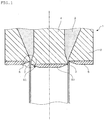
- FIG. 1 is a cross-sectional view showing the outline of the essential parts of the extrusion die head of this embodiment, mainly the outlet thereof.
- FIG. 2 is an enlarged cross-sectional view of essential parts showing the part encircled by a dashed line in FIG. 1 .
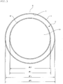
- FIG. 3 is a schematic plan view showing the vicinity of the outlet of the extrusion die head shown in FIG. 1 , as viewed from below.
- the extrusion die head 1 of this embodiment has a shell 2 forming an outlet 3 and a core 4 which is provided in the shell 2 with a predetermined gap being formed between the outlet 3 formed in the shell 2. Due to such a configuration, the extrusion die head 1 is installed to the front end part of an extruder (not shown), and a resin material which has been melt-kneaded by means of the extruder is extruded in a hollow shape from the outlet 3 which opens in a ring-like shape via a resin channel 5 formed between the shell 2 and the core 4.
- a plate-like shell tip 6 is detachably attached to the shell 2.
- an opening 7 is formed along the circumference of the outlet 3 formed in the shell 2 such that it is arranged to surround the outlet 3 (see FIG. 3 ). Also, non-sticky coating is applied to this shell tip 6.
- the shell tip 6 may be installed by an appropriate means such as bolt tightening such that the shell tip 6 does not fall during the operation of the device.
- a burned coating formed singly of a fluorine-based resin such as polytetrafluoroethylene (PTFE), perfluoroalkoxy (PFA), a tetrafluoroethylene/hexafluoropropylene copolymer (FEP) and an ethylene/tetrafluoroethylene copolymer (ETFE) or a mixture of these resins with other resin components having excellent heat resistance such as polyether ether ketone (PEEK), polyether sulfone (PES) can be given.
- a PFA-PEEK composite coating film obtained by mixing PFA and PEEK is preferable.
- Such a burned coating film can be formed in a thickness of about 30 to 130 ⁇ m by a process in which a dispersion to which various additives are added together with the above-mentioned resin components is applied on a metal matrix which has been pre-coated according to need, followed by burning at a predetermined temperature.
- such a shell tip 6 is attached to the opening side of the outlet 3, and the opening 7 of the shell tip 6 to which non-sticky coating has been applied is arranged along the circumference of the outlet 3 in such a manner that the opening 7 surrounds the outlet 3.
- the resin extruded from the extrusion die head 1 is hardly adhered to the outlet 3, whereby a deteriorated resin, which is considered to be a cause of a die drool, is prevented from being accumulated in the outlet 3, and generation of a die drool can be suppressed completely or for a long period of time.
- the shell tip 6 can be removed when cleaning the extrusion die head 1 according to need such as the case of the maintenance of the apparatus or the exchange of a resin, thereby cleaning is facilitated.
- cleaning can be completed within a shorter period of time.
- non-sticky coating applied to the shell tip 6 be applied along at least the inner circumference of the opening 7 formed in the shell tip 6.
- the coating is applied so that the coating is extended to the surface of the shell tip 6 on which the shell tip 6 is attached to the shell 2, that is, the surface opposing to the shell 2.
- non-sticky coating may be applied to the entire surface of the shell tip 6.
- non-sticky coating is applied to the entire surface of the shell tip 6.
- the diameter ⁇ B of the opening 7 formed in the shell tip 6 it is preferred that it be equal to or larger than the diameter ⁇ A of the outlet 3 ( ⁇ A ⁇ B).
- the diameter ⁇ A of the outlet 3 formed in the shell 2 and the diameter ⁇ B of the opening 7 formed in the shell tip 6 satisfy the relationship ⁇ B ⁇ A + 0.2 mm. It is preferred that both diameters be appropriately adjusted in a scope that can attain the initial object in such a manner that the diameter ⁇ B of the opening 7 become slightly larger than the diameter ⁇ A of the outlet 3.
- a tapered part 8 having a diameter which increases along the extrusion direction of a resin is provided in an opening side of the shell tip 6 as shown in FIG. 1 . Due to such a configuration, the resin which has been extruded from the outlet 3 hardly adheres to the opening 7 of the shell tip 6. As a result, accumulation of the deteriorated resin can be more effectively avoided, whereby generation of a die drool can be more effectively suppressed.
- the angle ⁇ a of inclination of the tapered part 8 relative to the surface of the shell tip 6 on which the shell tip 6 is attached to the shell 2, i.e. the surface opposing to the shell 2 is preferably equal to or smaller than 20°. By allowing the angle to be such a value, adhesion of the resin to the shell tip 6 can be suppressed more effectively.
- the inner circumference of the opening 7 be allowed to be an inside surface 9 which has a thickness Ta of 0.1 to 0.5 mm which is in parallel with the extrusion direction of the resin (see FIG. 2 ). Further, by forming the inside surface 9 having such a thickness in the inner circumference of the opening 7, application of non-sticky coating along the inner circumference of the opening 7 becomes easy.
- the thickness Ta of the inside surface 9 exceeds the upper limit of the above-mentioned range, similar effects can be obtained. However, in respect of preventing the shell tip 6 from increasing in thickness more than required and reducing the part to which the coating is applied, the upper limit of the thickness of the inside surface 9 is set.
- a core tip 10 to which similar non-sticky coating is applied, is detachably attached to the core 4 which forms the outlet 3 together with the shell 2. Due to such a configuration, the resin extruded from the extrusion die head 1 is hardly adhered to the core 4, whereby generation of a die drool on the side of the core 4 can be suppressed.
- a plate-like core tip 10 is attached such that the front end surface of the core 4 is covered.
- the core tip 10 when the core tip 10 is detachably attached to the core 4, as explained above by referring to the shell tip 6, the core tip 10 may be attached by an appropriate means such as bolt tightening.
- the core tip 10 By detachably attaching the core tip 10 to the core 4, the core tip 10 can be removed when cleaning the extrusion die head 1 according to need. As a result, cleaning is facilitated. As explained above by referring to the shell tip 6, by exchanging the core tip 10 removed from the core 4 by the cleaned core tip 10 or the new core tip 10, cleaning can be completed within a shorter period of time.
- non-sticky coating applied to the core tip 10 be applied along at least the outer circumference of the core tip 10.
- the coating be applied so that the coating is extended to the surface of the core tip 10 on which the core tip 10 is attached to the core 4, that is, the surface opposing the core 4.
- non-sticky coating may be applied to the entire surface of the core tip 10.
- non-sticky coating is applied to the entire surface of the core tip 10.
- the dimension of ⁇ D be set in such a manner that ⁇ D becomes equal to or smaller than the outer diameter ⁇ C of the front surface of the core 4 ( ⁇ D ⁇ C) in order not to hinder the flow of the resin extruded from the outlet 3.
- the outer diameter ⁇ D of the core tip 10 and the outer diameter ⁇ C of the front surface of the core 4 satisfy the relationship ⁇ C ⁇ D + 0.2 mm. It is preferred that both diameters be appropriately adjusted such that the outer diameter ⁇ D of the core tip 10 becomes slightly smaller than the outer diameter ⁇ C of the front surface of the core 4.
- the inclination angle ⁇ b of the tapered part 11 relative to the surface of the core tip 10 on which the core tip 10 is attached to the core 4, i.e. the surface opposing to the core 4, is preferably equal to or smaller than 20°.
- the outer circumference of the core tip 10 is allowed to be an outside surface 12 having a thickness Tb of 0.1 to 0.5 mm which is in parallel with the extrusion direction of the resin (see FIG. 2 ), and by forming the outside surface 12 having a thickness Tb, application of non-sticky coating along the outer circumference of the core tip 10 becomes easy, as mentioned above by referring to the shell tip 6.
- the upper limit of the thickness Tb of the outside surface 12 is set, as mentioned above by referring to the shell tip 6.
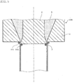
- FIG. 4 is a cross-sectional view showing the outline of the essential parts of the extrusion die head of this embodiment, mainly the outlet thereof.
- the core tip 10 is detachably attached to the core 4, and non-sticky coating is applied to the core tip 10.
- This embodiment is different from the first embodiment in that non-sticky coating is directly applied to the core 4.
- the core front end part 4a is removable from the base part 4b.
- the non-sticky coating is applied to the entire surface of the core front end part 4a.
- the core front end part 4a is fixed to the base part 4b by an appropriate means such as bolt tightening.
- non-sticky coating is directly applied to the core 4, it suffices that the coating be applied along at least the front edge part 4c of the core 4. However, in order to prevent peeling off of coating with the passage of time, it is preferred that not only the coating be applied from a front edge part 4c of the removed core front end part 4a which is removable from the base part 4b to said surface of the core front end part 4a, but also the coating be applied so that the coating is extended to the surface opposing to the base part 4b. Further, in respect of facilitating coating operation, like the example shown in FIG. 4 , it is preferred that non-sticky coating be applied to the entire surface of the core front end part 4a.
- This embodiment differs from the above-mentioned first embodiment in the above-mentioned points.
- This embodiment and the first embodiment are the same in other constitutions, and hence, a detailed explanation on the other constitutions is omitted here.
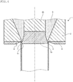
- the outline of the conventional extrusion die head is shown in FIG. 5 .
- a cylindrical parison is continuously molded by injection by using a resin material such as a polyolefin-based resin by using such extrusion die head 100, the production line had to be stopped at every 60 to 90 minutes in order to remove the die drool 101.
- FIG. 5 is a cross-sectional view showing the outline of the essential parts of one example of the conventional extrusion die head, mainly the outlet.
- the elements common to those in the extrusion die head 1 shown in FIG. 1 they are indicated by the same numerals and the explanation thereof is omitted.
- the conventional extrusion die head shown in FIG. 5 has been improved to that shown in FIG. 1 .
- the shell tip 6 on which the non-sticky coating is applied on the entire surface is attached to the opening side of the outlet 3, and the opening 7 of the shell tip 6 is arranged along the circumference of the outlet 3 in such a manner that it surrounds the outlet 3.
- the core tip 10 on the entire surface of which the non-sticky coating is applied is attached so as to cover the front side surface of the core 4.
- a PFA-PEEK composite coating film is burned in an average thickness of 100 ⁇ m.
- the core 4 in the shell 2 can be provided between the shell 2 and the outlet 3 formed in the shell 2 with a predetermined gap being formed therebetween, and the molten resin is extruded like a hollow shape.
- the core 4 can be an extrusion die head from which the molten resin is extruded in a solid shape.
- the shell tip 6 as mentioned above may be detachably attached to the shell 2.
- the shell tip 6 or the core tip 10 on which the above-mentioned coating is applied can be attached to a conventional extrusion die head or non-sticky coating can be applied to the core 4.
- the present invention can be applied to an extrusion die head which is attached to the front of the extruder and used for extruding a molten resin.
Landscapes
- Engineering & Computer Science (AREA)
- Mechanical Engineering (AREA)
- Manufacturing & Machinery (AREA)
- Extrusion Moulding Of Plastics Or The Like (AREA)
Description
- The prevent invention relates to an extrusion die head for extruding a molten resin material which is provided at the front end part of an extruder and is used to extrude a molten resin such that it has a predetermined cross-sectional shape.
- In extrusion molding, in general, by extruding a resin material which has been melt-kneaded by means of an extruder through a resin channel formed in a channel in an extrusion die head provided at the front end part of the extruder, a molded article having a predetermined cross-sectional shape is continuously shaped. It is known that, at this time, when molding is continued for a long period of time, a deteriorated resin is adhered to the outlet of the extrusion die head (see
FIG. 5 which shows the outline of one example of a conventional extrusion die head). Such an adhered matter is generally referred to as a die drool. If molding is continued with a die drool being adhered to the outlet of the extrusion die head, problems occur that the die drool is mixed in a molded article, whereby the quality of the molded article is deteriorated and traces of the die drool (die lines) are formed on the surface of the molded article in the form of a line to deteriorate the external appearance of the molded article. - In order to prevent a die drool from being formed, it is required to conduct troublesome works, i.e. to stop the molding at a predetermined interval and dismantle and clean the extrusion die head. Further, whenever the molding is stopped, the production line must be suspended, and as a result, removal of a die drool results in lowering in productivity.
- Conventionally, in order to prevent generation of such a die drool, various technologies have been proposed. For example, in
Patent Document 1, a nozzle piece is installed to a die plate in an exchangeable manner, and a die drool is removed together with the nozzle piece, whereby the time or cost incurred for the removal of a die drool is attempted to be reduced. InPatent Document 2, a cylindrical member having a tapered part in the inside thereof is installed to a die lip part, whereby the die drool generated in the die lip part is adhered to the tapered part and is then transferred from the die lip part to the tapered part by extrusion force, whereby the die drool is removed.Patent Document 3 shows an extrusion head with a tapered part of the shell, wherein the angle of inclination is about 70° with respect to a surface perpendicular to the extrusion direction.Patent Document 4 discloses an extrusion head with a flat shell tip that is attached to the shell by a metal ring that is tapered.Patent Document 5 shows an extrusion head with a flat shell tip inserted in the outer surface of the shell.Patent Document 6 discloses an extrusion head, wherein a flat shell tip is placed on the outer surface of the shell.Patent Document 7 shows an extrusion head, wherein a flat shell tip is placed on the outer surface of the shell. -
- Patent Document 1:
JP-A-2000-52403 - Patent Document 2:
JP-A-2005-111803 - Patent Document 3:
EP 1 334 815 A1 - Patent Document 4:
BE 1 009 344 A3 - Patent Document 5:
EP 0 838 322 A2 - Patent Document 6:
JP-A-2000-198136 - Patent Document 7:
JP-U-S59-2528 - However, in a technology disclosed in
Patent Document 1, although the time or cost required for the removal of a die drool can be decreased, the production line has to be stopped when the nozzle piece is exchanged. Therefore, the productivity cannot be increased by the technology disclosed inPatent Document 1. In addition, in a technology disclosed inPatent Document 2, when a cylindrical parison or the like is molded by extrusion which is used in blow molding, for example, it is impossible to remove a die drool generated inside such a parison. That is, in any of conventional technologies, satisfactory results cannot be obtained. - Generation mechanism of a die drool is so complicated, and the full picture thereof has not been elucidated yet. The inventors made extensive studies taking into consideration the fact that the resin adhered to the outlet of the extrusion die head is gradually deposited while being deteriorated with the passage of time. The inventors have found that, by allowing a resin to be hardly adhered to the outlet of an extrusion die head, generation of a die drool can be suppressed. The present invention has been made based an this finding. That is, an object of the present invention is to provide an extrusion die head which can suppress generation of a die drool in the outlet of the die head when extrusion molding is conducted continuously for a long period of time.
- The invention includes an extrusion die head according to
claim 1 attached to front end part of an extruder. - According to the extrusion die head of the present invention, it is possible to prevent generation of a die drool at the outlet thereof completely or for a long period of time.
-
-
FIG. 1 is a cross-sectional view of essential parts showing the outline of the first embodiment of the extrusion die head according to the present invention; -
FIG. 2 is an enlarged cross-sectional view of essential parts of the first embodiment of the extrusion die head according to the present invention; -
FIG. 3 is a schematic plan view of the vicinity of the outlet of the extrusion die head according to the present invention shown inFIG. 1 , as viewed from below; -
FIG. 4 is a cross-sectional view of essential parts showing the outline of the second embodiment of the extrusion die head according to the present invention; and -
FIG. 5 is a cross-sectional view of essential parts showing the outline of a conventional extrusion die head. - Hereinbelow, embodiments of the extrusion die head of the present invention will be explained with reference to the drawings.
- At first, the first embodiment of the extrusion die head of the present invention will be explained.
-
FIG. 1 is a cross-sectional view showing the outline of the essential parts of the extrusion die head of this embodiment, mainly the outlet thereof.FIG. 2 is an enlarged cross-sectional view of essential parts showing the part encircled by a dashed line inFIG. 1 .FIG. 3 is a schematic plan view showing the vicinity of the outlet of the extrusion die head shown inFIG. 1 , as viewed from below. - In these drawings, the dimension of each part is depicted in an exaggerated manner, according to need (the same can be applied to
FIGs. 4 and5 , mentioned later). - The
extrusion die head 1 of this embodiment has ashell 2 forming anoutlet 3 and acore 4 which is provided in theshell 2 with a predetermined gap being formed between theoutlet 3 formed in theshell 2. Due to such a configuration, theextrusion die head 1 is installed to the front end part of an extruder (not shown), and a resin material which has been melt-kneaded by means of the extruder is extruded in a hollow shape from theoutlet 3 which opens in a ring-like shape via aresin channel 5 formed between theshell 2 and thecore 4. - In the example shown in
FIG. 1 , on the opening side of the outlet 3 (in the figure, the lower side of the shell 2), a plate-like shell tip 6 is detachably attached to theshell 2. In thisshell tip 6, anopening 7 is formed along the circumference of theoutlet 3 formed in theshell 2 such that it is arranged to surround the outlet 3 (seeFIG. 3 ). Also, non-sticky coating is applied to thisshell tip 6. - Although not particularly shown, in order to install the
shell tip 6 detachably to theshell 2, theshell tip 6 may be installed by an appropriate means such as bolt tightening such that theshell tip 6 does not fall during the operation of the device. - No specific restrictions are imposed on the type of the non-sticky coating to be applied to the
shell tip 6 as long as it is coating to which a resin extruded from theoutlet 3 hardly adheres. For example, a burned coating formed singly of a fluorine-based resin such as polytetrafluoroethylene (PTFE), perfluoroalkoxy (PFA), a tetrafluoroethylene/hexafluoropropylene copolymer (FEP) and an ethylene/tetrafluoroethylene copolymer (ETFE) or a mixture of these resins with other resin components having excellent heat resistance such as polyether ether ketone (PEEK), polyether sulfone (PES) can be given. In particular, for the reason that the wear resistance is so excellent, and hence scratches hardly affect adversely the product, a PFA-PEEK composite coating film obtained by mixing PFA and PEEK is preferable. - Such a burned coating film can be formed in a thickness of about 30 to 130 µm by a process in which a dispersion to which various additives are added together with the above-mentioned resin components is applied on a metal matrix which has been pre-coated according to need, followed by burning at a predetermined temperature.
- In the
extrusion die head 1 of this embodiment, such ashell tip 6 is attached to the opening side of theoutlet 3, and theopening 7 of theshell tip 6 to which non-sticky coating has been applied is arranged along the circumference of theoutlet 3 in such a manner that the opening 7 surrounds theoutlet 3. As a result, the resin extruded from theextrusion die head 1 is hardly adhered to theoutlet 3, whereby a deteriorated resin, which is considered to be a cause of a die drool, is prevented from being accumulated in theoutlet 3, and generation of a die drool can be suppressed completely or for a long period of time. - Further, by attaching the
shell tip 6 detachably to theshell 2, theshell tip 6 can be removed when cleaning the extrusion diehead 1 according to need such as the case of the maintenance of the apparatus or the exchange of a resin, thereby cleaning is facilitated. By exchanging theshell tip 6 removed from theshell 2 by the cleanedshell tip 6 or thenew shell tip 6, cleaning can be completed within a shorter period of time. - It suffices that the non-sticky coating applied to the
shell tip 6 be applied along at least the inner circumference of theopening 7 formed in theshell tip 6. However, in order to prevent peeling off of the coating with the passage of time, it is preferred that the coating is applied so that the coating is extended to the surface of theshell tip 6 on which theshell tip 6 is attached to theshell 2, that is, the surface opposing to theshell 2. In respect of facilitating coating operation, non-sticky coating may be applied to the entire surface of theshell tip 6. - In the example shown in
FIG. 1 , non-sticky coating is applied to the entire surface of theshell tip 6. - As for the diameter øB of the
opening 7 formed in theshell tip 6, it is preferred that it be equal to or larger than the diameter øA of the outlet 3 (øA≦øB). - However, if the inner circumference of the
opening 7 formed in theshell tip 6 is too distant from the circumference of theoutlet 3, there is a tendency that the initial object, i.e. to allow the resin to be hardly adhered to theoutlet 3, cannot be attained. In order to prevent such a disadvantage, it is preferred that the diameter øA of theoutlet 3 formed in theshell 2 and the diameter øB of theopening 7 formed in theshell tip 6 satisfy the relationship øB≦øA + 0.2 mm. It is preferred that both diameters be appropriately adjusted in a scope that can attain the initial object in such a manner that the diameter øB of theopening 7 become slightly larger than the diameter øA of theoutlet 3. - According to the invention, a
tapered part 8 having a diameter which increases along the extrusion direction of a resin is provided in an opening side of theshell tip 6 as shown inFIG. 1 . Due to such a configuration, the resin which has been extruded from theoutlet 3 hardly adheres to theopening 7 of theshell tip 6. As a result, accumulation of the deteriorated resin can be more effectively avoided, whereby generation of a die drool can be more effectively suppressed. Moreover, the angle θa of inclination of thetapered part 8 relative to the surface of theshell tip 6 on which theshell tip 6 is attached to theshell 2, i.e. the surface opposing to theshell 2, is preferably equal to or smaller than 20°. By allowing the angle to be such a value, adhesion of the resin to theshell tip 6 can be suppressed more effectively. - With such a
tapered part 8 provided in theopening 7 side of theshell tip 6, if the inner circumference of theopening 7 has a sharp edge-like shape, a line-shaped trace may be formed on the surface of the extruded resin.
In order to prevent such a disadvantage, it is preferred that the inner circumference of theopening 7 be allowed to be aninside surface 9 which has a thickness Ta of 0.1 to 0.5 mm which is in parallel with the extrusion direction of the resin (seeFIG. 2 ). Further, by forming theinside surface 9 having such a thickness in the inner circumference of theopening 7, application of non-sticky coating along the inner circumference of theopening 7 becomes easy. - If the thickness Ta of the
inside surface 9 exceeds the upper limit of the above-mentioned range, similar effects can be obtained. However, in respect of preventing theshell tip 6 from increasing in thickness more than required and reducing the part to which the coating is applied, the upper limit of the thickness of theinside surface 9 is set. - On the other hand, in this embodiment, a
core tip 10, to which similar non-sticky coating is applied, is detachably attached to thecore 4 which forms theoutlet 3 together with theshell 2. Due to such a configuration, the resin extruded from the extrusion diehead 1 is hardly adhered to thecore 4, whereby generation of a die drool on the side of thecore 4 can be suppressed. - When the
core tip 10 is detachably attached to thecore 4, in the example shown inFIG. 1 , a plate-like core tip 10 is attached such that the front end surface of thecore 4 is covered. - Not particularly shown, when the
core tip 10 is detachably attached to thecore 4, as explained above by referring to theshell tip 6, thecore tip 10 may be attached by an appropriate means such as bolt tightening. - By detachably attaching the
core tip 10 to thecore 4, thecore tip 10 can be removed when cleaning the extrusion diehead 1 according to need. As a result, cleaning is facilitated. As explained above by referring to theshell tip 6, by exchanging thecore tip 10 removed from thecore 4 by the cleanedcore tip 10 or thenew core tip 10, cleaning can be completed within a shorter period of time. - It suffices that the non-sticky coating applied to the
core tip 10 be applied along at least the outer circumference of thecore tip 10. As in the case of applying coating to theshell tip 6, in order to prevent the coating from peeling off with the passage of time, it is preferred that the coating be applied so that the coating is extended to the surface of thecore tip 10 on which thecore tip 10 is attached to thecore 4, that is, the surface opposing thecore 4. In respect of facilitating the coating operation, non-sticky coating may be applied to the entire surface of thecore tip 10. - In the example shown in
FIG. 1 , non-sticky coating is applied to the entire surface of thecore tip 10. - As for the outer diameter øD of the
core tip 10, it is preferred that the dimension of øD be set in such a manner that øD becomes equal to or smaller than the outer diameter øC of the front surface of the core 4 (øD≦øC) in order not to hinder the flow of the resin extruded from theoutlet 3. - In this case, in order not to allow the outer circumference of the
core tip 10 to be too distant from the circumference of the front surface of thecore 4, t is preferred that the outer diameter øD of thecore tip 10 and the outer diameter øC of the front surface of thecore 4 satisfy the relationship øC≦øD + 0.2 mm. It is preferred that both diameters be appropriately adjusted such that the outer diameter øD of thecore tip 10 becomes slightly smaller than the outer diameter øC of the front surface of thecore 4. - On the outer circumference of the
core tip 10, as shown inFIG. 1 , it is possible to provide atapered part 11 which is decreased in diameter along the extrusion direction of the resin. Due to such a configuration, the resin which has been extruded from theoutlet 3 more hardly adheres to thecore tip 10. As a result, accumulation of the deteriorated resin can be more effectively avoided, whereby generation of a die drool can be more effectively suppressed. - At this time, the inclination angle θb of the
tapered part 11 relative to the surface of thecore tip 10 on which thecore tip 10 is attached to thecore 4, i.e. the surface opposing to thecore 4, is preferably equal to or smaller than 20°. By allowing the inclination angle to be such a value, adhesion of the resin to thecore tip 10 can be suppressed more effectively, as explained above referring to theshell tip 6. - Further, when such
tapered part 11 is provided in the outer circumference of thecore tip 10, in order to prevent a disadvantage that a line-shaped trace may be formed on the surface of the extruded resin, it is preferred that the outer circumference of thecore tip 10 is allowed to be anoutside surface 12 having a thickness Tb of 0.1 to 0.5 mm which is in parallel with the extrusion direction of the resin (seeFIG. 2 ), and by forming theoutside surface 12 having a thickness Tb, application of non-sticky coating along the outer circumference of thecore tip 10 becomes easy, as mentioned above by referring to theshell tip 6. Not only to prevent thecore tip 10 from increasing in thickness more than required, but also to reduce the part to which the coating is applied, the upper limit of the thickness Tb of theoutside surface 12 is set, as mentioned above by referring to theshell tip 6. - Next, the second embodiment of the extrusion die head of the present invention will be described.
-
FIG. 4 is a cross-sectional view showing the outline of the essential parts of the extrusion die head of this embodiment, mainly the outlet thereof. - In the first embodiment mentioned above, the
core tip 10 is detachably attached to thecore 4, and non-sticky coating is applied to thecore tip 10. This embodiment is different from the first embodiment in that non-sticky coating is directly applied to thecore 4. - In the example shown in
FIG. 4 , the corefront end part 4a is removable from thebase part 4b. The non-sticky coating is applied to the entire surface of the corefront end part 4a. Not particularly shown, the corefront end part 4a is fixed to thebase part 4b by an appropriate means such as bolt tightening. - If non-sticky coating is directly applied to the
core 4, it suffices that the coating be applied along at least thefront edge part 4c of thecore 4. However, in order to prevent peeling off of coating with the passage of time, it is preferred that not only the coating be applied from afront edge part 4c of the removed corefront end part 4a which is removable from thebase part 4b to said surface of the corefront end part 4a, but also the coating be applied so that the coating is extended to the surface opposing to thebase part 4b. Further, in respect of facilitating coating operation, like the example shown inFIG. 4 , it is preferred that non-sticky coating be applied to the entire surface of the corefront end part 4a. - This embodiment differs from the above-mentioned first embodiment in the above-mentioned points. This embodiment and the first embodiment are the same in other constitutions, and hence, a detailed explanation on the other constitutions is omitted here.
- The present invention will be explained in more detail with reference to the following specific examples.
- The outline of the conventional extrusion die head is shown in
FIG. 5 . When a cylindrical parison is continuously molded by injection by using a resin material such as a polyolefin-based resin by using suchextrusion die head 100, the production line had to be stopped at every 60 to 90 minutes in order to remove thedie drool 101. -
FIG. 5 is a cross-sectional view showing the outline of the essential parts of one example of the conventional extrusion die head, mainly the outlet. As for the elements common to those in the extrusion diehead 1 shown inFIG. 1 , they are indicated by the same numerals and the explanation thereof is omitted. - The conventional extrusion die head shown in
FIG. 5 has been improved to that shown inFIG. 1 . Specifically, theshell tip 6 on which the non-sticky coating is applied on the entire surface is attached to the opening side of theoutlet 3, and theopening 7 of theshell tip 6 is arranged along the circumference of theoutlet 3 in such a manner that it surrounds theoutlet 3. On the other hand, thecore tip 10 on the entire surface of which the non-sticky coating is applied is attached so as to cover the front side surface of thecore 4. As the non-sticky coating, a PFA-PEEK composite coating film is burned in an average thickness of 100 µm. - Using the extrusion die
head 1, a cylindrical parison was molded by extrusion continuously under the conditions same as those of conventional conditions. The outlet was observed after the lapse of 720 minutes from the start of molding, and generation of a die drool was not confirmed. - The
core 4 in theshell 2 can be provided between theshell 2 and theoutlet 3 formed in theshell 2 with a predetermined gap being formed therebetween, and the molten resin is extruded like a hollow shape. By omitting the provision of thecore 4, or by other methods, it can be an extrusion die head from which the molten resin is extruded in a solid shape. In this case, theshell tip 6 as mentioned above may be detachably attached to theshell 2. - Moreover, the
shell tip 6 or thecore tip 10 on which the above-mentioned coating is applied can be attached to a conventional extrusion die head or non-sticky coating can be applied to thecore 4. - As mentioned hereinabove, the present invention can be applied to an extrusion die head which is attached to the front of the extruder and used for extruding a molten resin.
-
- 1.
- Extrusion die head
- 2.
- Shell
- 3.
- Outlet
- 4.
- Core
- 6.
- Shell tip
- 7.
- Opening
- 8.
- Tapered part
- 9.
- Inside surface
- 10.
- Core tip
- 11.
- Tapered part
- 12.
- Outside surface
- øA
- Diameter of the outlet formed in the shell
- øB
- Diameter of the opening formed in the shell tip
- øC
- Outer diameter of the front end surface of the core
- øD
- Outer diameter of the core tip
Claims (13)
- An extrusion die head (1) adapted to be attached to a front end part of an extruder, comprising:a shell (2) having an outlet (3) for extruding a resin material which has been melt-kneaded by means of the extruder;a plate-like shell tip (6) having an opening (7) to be arranged along a circumference of the outlet (3) in such a manner that the opening (7) surrounds the outlet (3),the shell tip (6) being detachably attached to the shell (2); anda non-sticky coating being applied at least along an inner circumference of the opening (7) formed in the shell tip (6),characterized bya tapered part (8) provided in an opening side of the shell tip (6) and having a in diameter which increases along an extrusion direction of the resin,wherein an angle of inclination of the tapered part (8) relative to a surface of the shell tip (6) on which the shell tip (6) is attached to the shell (2) is equal to or smaller than 20°.
- The extrusion die head (1) according to claim 1, wherein an inner surface of the opening (7) of the shell tip (6) has a thickness of 0.1 to 0.5 mm which is in parallel with the extrusion direction of the resin.
- The extrusion die head (1) according to claim 1 or 2, wherein a diameter of the outlet (3) øA formed in the shell (2) and a diameter of the opening (7) øB formed in the shell tip (6) satisfy the following relationship:

- The extrusion die head (1) according to claim 3, wherein the diameter of the outlet (3) øA formed in the shell (2) and the diameter of the opening (7) øB formed in the shell tip (6) satisfy the following relationship:

- The extrusion die head (1) according to any one of claims 1 to 4, further comprising:a core (4) provided in the shell (2) with a predetermined gap being formed between the outlet (3) formed in the shell (2) such that the resin which has been melt-kneaded by means of the extruder is extruded in a hollow shape;a plate-like core tip (10) covering a front surface of the core (4);the core tip (10) detachably attached to the core (4); anda non-sticky coating applied at least along an outer surface of the core tip (10).
- The extrusion die head (1) according to claim 5, wherein a tapered part (11) which is decreased in diameter along the extrusion direction of the resin is provided on an outer circumference side of the core tip (10).
- The extrusion die head (1) according to claim 6, wherein an angle of inclination of the tapered part (11) relative to a surface of the core tip (10) on which the core tip (10) is attached to the core (4) is equal to or smaller than 20°.
- The extrusion die head (1) according to any of claims 5 to 7, wherein an outer circumference of the core tip (10) includes an outside surface (12) having a thickness of 0.1 to 0.5 mm which is in parallel with the extrusion direction of the resin.
- The extrusion die head (1) according any one of claims 5 to 8, wherein the outer diameter øC of a front surface of the core (4) and an outer diameter øD of the core tip (10) satisfy the following relationship:

- The extrusion die head (1) according to claim 9, wherein the outer diameter øC of the front surface of the core (4) and outer diameter øD of the core tip (10) satisfy the following relationship:

- The extrusion die head (1) according to any one of claims 1 to 4, further comprising; a core (4) provided in the shell (2) with a predetermined gap being formed between the outlet (3) formed in the shell (2) such that the resin which has been melt-kneaded by means of the extruder is extruded in a hollow shape;
wherein a non-sticky coating is applied at least along a front edge part of the core (4). - The extrusion die head (1) according to claims 1 to 11, wherein the non-sticky coating is a burned coating film comprising a fluorine-based resin.
- The extrusion die head (1) according to claim 12, wherein the burned coating film comprising the fluorine-based resin is a PFA-PEEK composite coating film.
Applications Claiming Priority (2)
| Application Number | Priority Date | Filing Date | Title |
|---|---|---|---|
| JP2010167215A JP4998606B2 (en) | 2010-07-26 | 2010-07-26 | Extrusion die head |
| PCT/JP2011/003915 WO2012014389A1 (en) | 2010-07-26 | 2011-07-07 | Extrusion die head |
Publications (3)
| Publication Number | Publication Date |
|---|---|
| EP2599609A1 EP2599609A1 (en) | 2013-06-05 |
| EP2599609A4 EP2599609A4 (en) | 2015-05-27 |
| EP2599609B1 true EP2599609B1 (en) | 2017-08-30 |
Family
ID=45529626
Family Applications (1)
| Application Number | Title | Priority Date | Filing Date |
|---|---|---|---|
| EP11811994.0A Not-in-force EP2599609B1 (en) | 2010-07-26 | 2011-07-07 | Extrusion die head |
Country Status (6)
| Country | Link |
|---|---|
| US (1) | US8985992B2 (en) |
| EP (1) | EP2599609B1 (en) |
| JP (1) | JP4998606B2 (en) |
| KR (1) | KR101444625B1 (en) |
| CN (1) | CN103052488B (en) |
| WO (1) | WO2012014389A1 (en) |
Families Citing this family (6)
| Publication number | Priority date | Publication date | Assignee | Title |
|---|---|---|---|---|
| CN104220226A (en) | 2012-03-30 | 2014-12-17 | 住友电工超效能高分子股份有限公司 | Resin-releasing jig |
| CN102825771A (en) * | 2012-09-06 | 2012-12-19 | 住电光纤光缆(深圳)有限公司 | Plastic extruding machine and method for processing slobbering of die stripping outlet thereof |
| DE102013202798A1 (en) * | 2013-02-21 | 2014-08-21 | Battenfeld-Cincinnati Germany Gmbh | Device for producing plastic pipes |
| DE102013202799A1 (en) * | 2013-02-21 | 2014-08-21 | Battenfeld-Cincinnati Germany Gmbh | Device for producing plastic pipes |
| CN103331798B (en) * | 2013-06-18 | 2016-01-20 | 泗阳蓝阳托盘设备科技有限公司 | The not stratified plant fiber extruder of vertical structure |
| CN103660227A (en) * | 2014-01-10 | 2014-03-26 | 长园电子(集团)有限公司 | Plastic pipe extruding opening mold |
Family Cites Families (15)
| Publication number | Priority date | Publication date | Assignee | Title |
|---|---|---|---|---|
| DE2610668C2 (en) * | 1976-03-13 | 1982-08-19 | Elbatainer Kunststoff- Und Verpackungsgesellschaft Mbh, 7505 Ettlingen | Device for producing hollow bodies from thermoplastic material |
| JPS5355687U (en) * | 1976-10-14 | 1978-05-12 | ||
| JPS592528U (en) * | 1982-06-28 | 1984-01-09 | 出光石油化学株式会社 | Die for resin extrusion molding |
| JPH06190904A (en) * | 1992-12-25 | 1994-07-12 | Ube Ind Ltd | Flat die for blow molding |
| JP3368928B2 (en) * | 1993-01-05 | 2003-01-20 | 積水化学工業株式会社 | Extrusion mold manufacturing method |
| BE1009344A3 (en) * | 1995-04-12 | 1997-02-04 | Dyka Plastics Naamloze Vennoot | Nozzle for extruding plastic |
| JP3678835B2 (en) * | 1996-02-28 | 2005-08-03 | 旭化成ケミカルズ株式会社 | Thermoplastic resin molding method |
| IE960898A1 (en) * | 1996-10-25 | 1998-05-06 | Menza Ltd | A method of and apparatus for blow-moulding |
| JP3295379B2 (en) | 1998-08-05 | 2002-06-24 | 株式会社日本製鋼所 | Strand die for extruder and method for preventing dies from forming |
| JP2000198136A (en) * | 1999-01-07 | 2000-07-18 | Japan Steel Works Ltd:The | Crosshead of blow molder |
| DE10205210B4 (en) * | 2002-02-08 | 2004-02-19 | Egeplast Werner Strumann Gmbh & Co. Kg | Device for the production of plastic pipes |
| JP2005111803A (en) * | 2003-10-07 | 2005-04-28 | Sekisui Chem Co Ltd | Deteriorated resin removing device |
| CN2875773Y (en) * | 2005-12-27 | 2007-03-07 | 朝日物产(天津)矿业有限公司 | Longitudinal coloured film extrusion machine |
| CN201064942Y (en) * | 2007-07-04 | 2008-05-28 | 汕头市新艺塑胶机械有限公司 | Hollow blow molding die head |
| CN201220477Y (en) * | 2008-03-28 | 2009-04-15 | 马镇鑫 | Novel plastic hollow molding storage type die head |
-
2010
- 2010-07-26 JP JP2010167215A patent/JP4998606B2/en active Active
-
2011
- 2011-07-07 US US13/808,797 patent/US8985992B2/en not_active Expired - Fee Related
- 2011-07-07 KR KR1020137001891A patent/KR101444625B1/en active IP Right Grant
- 2011-07-07 WO PCT/JP2011/003915 patent/WO2012014389A1/en active Application Filing
- 2011-07-07 CN CN201180036033.6A patent/CN103052488B/en not_active Expired - Fee Related
- 2011-07-07 EP EP11811994.0A patent/EP2599609B1/en not_active Not-in-force
Non-Patent Citations (1)
| Title |
|---|
| None * |
Also Published As
| Publication number | Publication date |
|---|---|
| EP2599609A4 (en) | 2015-05-27 |
| KR101444625B1 (en) | 2014-09-26 |
| EP2599609A1 (en) | 2013-06-05 |
| US8985992B2 (en) | 2015-03-24 |
| JP4998606B2 (en) | 2012-08-15 |
| CN103052488B (en) | 2015-05-27 |
| JP2012025079A (en) | 2012-02-09 |
| CN103052488A (en) | 2013-04-17 |
| KR20130041920A (en) | 2013-04-25 |
| WO2012014389A1 (en) | 2012-02-02 |
| US20130149406A1 (en) | 2013-06-13 |
Similar Documents
| Publication | Publication Date | Title |
|---|---|---|
| EP2599609B1 (en) | Extrusion die head | |
| US20110215499A1 (en) | Extrusion nozzle for polymers | |
| WO2010140310A1 (en) | Resin extrusion die and extrusion method using same | |
| US20200156309A1 (en) | 3d structures and methods therefor | |
| JP2007320056A (en) | Die for extrusion | |
| JP2009132102A (en) | T-die and its manufacturing method | |
| JP3910481B2 (en) | Method for manufacturing paper feed roller, paper feed roller manufactured by the manufacturing method, and device for manufacturing paper feed roller | |
| JP2011056762A (en) | Extruding apparatus of resin composition, and method for manufacturing resin composition | |
| JP3546875B2 (en) | Wire coating extrusion equipment | |
| US20020107326A1 (en) | Conical-front breaker plate and flow method | |
| CN212242238U (en) | Carbon-point extrusion device | |
| JP4321329B2 (en) | Die for resin molding and method for manufacturing resin molded product | |
| CN100364751C (en) | Co-extrusion tech. for thermal contraction double-wall pipe | |
| JPH01188317A (en) | Coloring method of plastic coated metallic pipe | |
| CN210915901U (en) | Heating plasticizing pipeline device for waste rubber desulfurization | |
| CN211074640U (en) | Flow dividing machine head for rubber tube extruder | |
| EP3130445B1 (en) | Shaping roll for melt extrusion molding, shaping roll assembly for melt extrusion molding, and melt extrusion molding method | |
| JP3560354B2 (en) | Mold in extrusion molding machine | |
| JP4234773B1 (en) | Extruder for molding hard vinyl chloride resin | |
| JP2007118500A (en) | Mold for extrusion molding | |
| JP4825512B2 (en) | Resin molding equipment | |
| CN110713620A (en) | Heating plasticizing pipeline device for waste rubber desulfurization | |
| JP6082600B2 (en) | Sheet extrusion product melt extrusion molding apparatus and melt extrusion molding method | |
| JP2003320573A (en) | T die | |
| JPH10119115A (en) | Die for resin pipe extrusion molding machine |
Legal Events
| Date | Code | Title | Description |
|---|---|---|---|
| PUAI | Public reference made under article 153(3) epc to a published international application that has entered the european phase |
Free format text: ORIGINAL CODE: 0009012 |
|
| 17P | Request for examination filed |
Effective date: 20130103 |
|
| AK | Designated contracting states |
Kind code of ref document: A1 Designated state(s): AL AT BE BG CH CY CZ DE DK EE ES FI FR GB GR HR HU IE IS IT LI LT LU LV MC MK MT NL NO PL PT RO RS SE SI SK SM TR |
|
| DAX | Request for extension of the european patent (deleted) | ||
| RA4 | Supplementary search report drawn up and despatched (corrected) |
Effective date: 20150424 |
|
| RIC1 | Information provided on ipc code assigned before grant |
Ipc: B29C 47/08 20060101ALI20150417BHEP Ipc: B29C 49/04 20060101ALN20150417BHEP Ipc: B29C 47/22 20060101AFI20150417BHEP |
|
| GRAP | Despatch of communication of intention to grant a patent |
Free format text: ORIGINAL CODE: EPIDOSNIGR1 |
|
| RIC1 | Information provided on ipc code assigned before grant |
Ipc: B29C 49/04 20060101ALN20170209BHEP Ipc: B29C 47/22 20060101AFI20170209BHEP Ipc: B29C 47/08 20060101ALI20170209BHEP |
|
| INTG | Intention to grant announced |
Effective date: 20170227 |
|
| GRAS | Grant fee paid |
Free format text: ORIGINAL CODE: EPIDOSNIGR3 |
|
| GRAJ | Information related to disapproval of communication of intention to grant by the applicant or resumption of examination proceedings by the epo deleted |
Free format text: ORIGINAL CODE: EPIDOSDIGR1 |
|
| GRAL | Information related to payment of fee for publishing/printing deleted |
Free format text: ORIGINAL CODE: EPIDOSDIGR3 |
|
| REG | Reference to a national code |
Ref country code: DE Ref legal event code: R079 Ref document number: 602011041155 Country of ref document: DE Free format text: PREVIOUS MAIN CLASS: B29C0047120000 Ipc: B29C0047220000 |
|
| GRAR | Information related to intention to grant a patent recorded |
Free format text: ORIGINAL CODE: EPIDOSNIGR71 |
|
| INTC | Intention to grant announced (deleted) | ||
| RIC1 | Information provided on ipc code assigned before grant |
Ipc: B29C 47/22 20060101AFI20170622BHEP Ipc: B29C 49/04 20060101ALN20170622BHEP Ipc: B29C 47/08 20060101ALI20170622BHEP |
|
| GRAA | (expected) grant |
Free format text: ORIGINAL CODE: 0009210 |
|
| INTG | Intention to grant announced |
Effective date: 20170626 |
|
| AK | Designated contracting states |
Kind code of ref document: B1 Designated state(s): AL AT BE BG CH CY CZ DE DK EE ES FI FR GB GR HR HU IE IS IT LI LT LU LV MC MK MT NL NO PL PT RO RS SE SI SK SM TR |
|
| REG | Reference to a national code |
Ref country code: GB Ref legal event code: FG4D |
|
| REG | Reference to a national code |
Ref country code: CH Ref legal event code: EP |
|
| REG | Reference to a national code |
Ref country code: AT Ref legal event code: REF Ref document number: 923098 Country of ref document: AT Kind code of ref document: T Effective date: 20170915 |
|
| REG | Reference to a national code |
Ref country code: IE Ref legal event code: FG4D |
|
| REG | Reference to a national code |
Ref country code: DE Ref legal event code: R096 Ref document number: 602011041155 Country of ref document: DE |
|
| REG | Reference to a national code |
Ref country code: NL Ref legal event code: MP Effective date: 20170830 |
|
| REG | Reference to a national code |
Ref country code: LT Ref legal event code: MG4D |
|
| REG | Reference to a national code |
Ref country code: AT Ref legal event code: MK05 Ref document number: 923098 Country of ref document: AT Kind code of ref document: T Effective date: 20170830 |
|
| PG25 | Lapsed in a contracting state [announced via postgrant information from national office to epo] |
Ref country code: LT Free format text: LAPSE BECAUSE OF FAILURE TO SUBMIT A TRANSLATION OF THE DESCRIPTION OR TO PAY THE FEE WITHIN THE PRESCRIBED TIME-LIMIT Effective date: 20170830 Ref country code: SE Free format text: LAPSE BECAUSE OF FAILURE TO SUBMIT A TRANSLATION OF THE DESCRIPTION OR TO PAY THE FEE WITHIN THE PRESCRIBED TIME-LIMIT Effective date: 20170830 Ref country code: NO Free format text: LAPSE BECAUSE OF FAILURE TO SUBMIT A TRANSLATION OF THE DESCRIPTION OR TO PAY THE FEE WITHIN THE PRESCRIBED TIME-LIMIT Effective date: 20171130 Ref country code: FI Free format text: LAPSE BECAUSE OF FAILURE TO SUBMIT A TRANSLATION OF THE DESCRIPTION OR TO PAY THE FEE WITHIN THE PRESCRIBED TIME-LIMIT Effective date: 20170830 Ref country code: AT Free format text: LAPSE BECAUSE OF FAILURE TO SUBMIT A TRANSLATION OF THE DESCRIPTION OR TO PAY THE FEE WITHIN THE PRESCRIBED TIME-LIMIT Effective date: 20170830 Ref country code: HR Free format text: LAPSE BECAUSE OF FAILURE TO SUBMIT A TRANSLATION OF THE DESCRIPTION OR TO PAY THE FEE WITHIN THE PRESCRIBED TIME-LIMIT Effective date: 20170830 |
|
| PG25 | Lapsed in a contracting state [announced via postgrant information from national office to epo] |
Ref country code: GR Free format text: LAPSE BECAUSE OF FAILURE TO SUBMIT A TRANSLATION OF THE DESCRIPTION OR TO PAY THE FEE WITHIN THE PRESCRIBED TIME-LIMIT Effective date: 20171201 Ref country code: BG Free format text: LAPSE BECAUSE OF FAILURE TO SUBMIT A TRANSLATION OF THE DESCRIPTION OR TO PAY THE FEE WITHIN THE PRESCRIBED TIME-LIMIT Effective date: 20171130 Ref country code: RS Free format text: LAPSE BECAUSE OF FAILURE TO SUBMIT A TRANSLATION OF THE DESCRIPTION OR TO PAY THE FEE WITHIN THE PRESCRIBED TIME-LIMIT Effective date: 20170830 Ref country code: ES Free format text: LAPSE BECAUSE OF FAILURE TO SUBMIT A TRANSLATION OF THE DESCRIPTION OR TO PAY THE FEE WITHIN THE PRESCRIBED TIME-LIMIT Effective date: 20170830 Ref country code: IS Free format text: LAPSE BECAUSE OF FAILURE TO SUBMIT A TRANSLATION OF THE DESCRIPTION OR TO PAY THE FEE WITHIN THE PRESCRIBED TIME-LIMIT Effective date: 20171230 Ref country code: LV Free format text: LAPSE BECAUSE OF FAILURE TO SUBMIT A TRANSLATION OF THE DESCRIPTION OR TO PAY THE FEE WITHIN THE PRESCRIBED TIME-LIMIT Effective date: 20170830 |
|
| PG25 | Lapsed in a contracting state [announced via postgrant information from national office to epo] |
Ref country code: NL Free format text: LAPSE BECAUSE OF FAILURE TO SUBMIT A TRANSLATION OF THE DESCRIPTION OR TO PAY THE FEE WITHIN THE PRESCRIBED TIME-LIMIT Effective date: 20170830 |
|
| PG25 | Lapsed in a contracting state [announced via postgrant information from national office to epo] |
Ref country code: CZ Free format text: LAPSE BECAUSE OF FAILURE TO SUBMIT A TRANSLATION OF THE DESCRIPTION OR TO PAY THE FEE WITHIN THE PRESCRIBED TIME-LIMIT Effective date: 20170830 Ref country code: PL Free format text: LAPSE BECAUSE OF FAILURE TO SUBMIT A TRANSLATION OF THE DESCRIPTION OR TO PAY THE FEE WITHIN THE PRESCRIBED TIME-LIMIT Effective date: 20170830 Ref country code: RO Free format text: LAPSE BECAUSE OF FAILURE TO SUBMIT A TRANSLATION OF THE DESCRIPTION OR TO PAY THE FEE WITHIN THE PRESCRIBED TIME-LIMIT Effective date: 20170830 Ref country code: DK Free format text: LAPSE BECAUSE OF FAILURE TO SUBMIT A TRANSLATION OF THE DESCRIPTION OR TO PAY THE FEE WITHIN THE PRESCRIBED TIME-LIMIT Effective date: 20170830 |
|
| PG25 | Lapsed in a contracting state [announced via postgrant information from national office to epo] |
Ref country code: SK Free format text: LAPSE BECAUSE OF FAILURE TO SUBMIT A TRANSLATION OF THE DESCRIPTION OR TO PAY THE FEE WITHIN THE PRESCRIBED TIME-LIMIT Effective date: 20170830 Ref country code: EE Free format text: LAPSE BECAUSE OF FAILURE TO SUBMIT A TRANSLATION OF THE DESCRIPTION OR TO PAY THE FEE WITHIN THE PRESCRIBED TIME-LIMIT Effective date: 20170830 Ref country code: IT Free format text: LAPSE BECAUSE OF FAILURE TO SUBMIT A TRANSLATION OF THE DESCRIPTION OR TO PAY THE FEE WITHIN THE PRESCRIBED TIME-LIMIT Effective date: 20170830 Ref country code: SM Free format text: LAPSE BECAUSE OF FAILURE TO SUBMIT A TRANSLATION OF THE DESCRIPTION OR TO PAY THE FEE WITHIN THE PRESCRIBED TIME-LIMIT Effective date: 20170830 |
|
| REG | Reference to a national code |
Ref country code: DE Ref legal event code: R097 Ref document number: 602011041155 Country of ref document: DE |
|
| PLBE | No opposition filed within time limit |
Free format text: ORIGINAL CODE: 0009261 |
|
| STAA | Information on the status of an ep patent application or granted ep patent |
Free format text: STATUS: NO OPPOSITION FILED WITHIN TIME LIMIT |
|
| REG | Reference to a national code |
Ref country code: FR Ref legal event code: PLFP Year of fee payment: 8 |
|
| 26N | No opposition filed |
Effective date: 20180531 |
|
| PG25 | Lapsed in a contracting state [announced via postgrant information from national office to epo] |
Ref country code: SI Free format text: LAPSE BECAUSE OF FAILURE TO SUBMIT A TRANSLATION OF THE DESCRIPTION OR TO PAY THE FEE WITHIN THE PRESCRIBED TIME-LIMIT Effective date: 20170830 |
|
| REG | Reference to a national code |
Ref country code: DE Ref legal event code: R079 Ref document number: 602011041155 Country of ref document: DE Free format text: PREVIOUS MAIN CLASS: B29C0047220000 Ipc: B29C0048325000 |
|
| REG | Reference to a national code |
Ref country code: CH Ref legal event code: PL |
|
| PG25 | Lapsed in a contracting state [announced via postgrant information from national office to epo] |
Ref country code: MC Free format text: LAPSE BECAUSE OF FAILURE TO SUBMIT A TRANSLATION OF THE DESCRIPTION OR TO PAY THE FEE WITHIN THE PRESCRIBED TIME-LIMIT Effective date: 20170830 Ref country code: LU Free format text: LAPSE BECAUSE OF NON-PAYMENT OF DUE FEES Effective date: 20180707 |
|
| REG | Reference to a national code |
Ref country code: BE Ref legal event code: MM Effective date: 20180731 |
|
| REG | Reference to a national code |
Ref country code: IE Ref legal event code: MM4A |
|
| PG25 | Lapsed in a contracting state [announced via postgrant information from national office to epo] |
Ref country code: CH Free format text: LAPSE BECAUSE OF NON-PAYMENT OF DUE FEES Effective date: 20180731 Ref country code: IE Free format text: LAPSE BECAUSE OF NON-PAYMENT OF DUE FEES Effective date: 20180707 Ref country code: LI Free format text: LAPSE BECAUSE OF NON-PAYMENT OF DUE FEES Effective date: 20180731 |
|
| PG25 | Lapsed in a contracting state [announced via postgrant information from national office to epo] |
Ref country code: BE Free format text: LAPSE BECAUSE OF NON-PAYMENT OF DUE FEES Effective date: 20180731 |
|
| PGFP | Annual fee paid to national office [announced via postgrant information from national office to epo] |
Ref country code: FR Payment date: 20190719 Year of fee payment: 9 Ref country code: DE Payment date: 20190719 Year of fee payment: 9 |
|
| PGFP | Annual fee paid to national office [announced via postgrant information from national office to epo] |
Ref country code: GB Payment date: 20190719 Year of fee payment: 9 |
|
| PG25 | Lapsed in a contracting state [announced via postgrant information from national office to epo] |
Ref country code: MT Free format text: LAPSE BECAUSE OF NON-PAYMENT OF DUE FEES Effective date: 20180707 |
|
| PG25 | Lapsed in a contracting state [announced via postgrant information from national office to epo] |
Ref country code: TR Free format text: LAPSE BECAUSE OF FAILURE TO SUBMIT A TRANSLATION OF THE DESCRIPTION OR TO PAY THE FEE WITHIN THE PRESCRIBED TIME-LIMIT Effective date: 20170830 |
|
| PG25 | Lapsed in a contracting state [announced via postgrant information from national office to epo] |
Ref country code: PT Free format text: LAPSE BECAUSE OF FAILURE TO SUBMIT A TRANSLATION OF THE DESCRIPTION OR TO PAY THE FEE WITHIN THE PRESCRIBED TIME-LIMIT Effective date: 20170830 Ref country code: HU Free format text: LAPSE BECAUSE OF FAILURE TO SUBMIT A TRANSLATION OF THE DESCRIPTION OR TO PAY THE FEE WITHIN THE PRESCRIBED TIME-LIMIT; INVALID AB INITIO Effective date: 20110707 |
|
| PG25 | Lapsed in a contracting state [announced via postgrant information from national office to epo] |
Ref country code: CY Free format text: LAPSE BECAUSE OF FAILURE TO SUBMIT A TRANSLATION OF THE DESCRIPTION OR TO PAY THE FEE WITHIN THE PRESCRIBED TIME-LIMIT Effective date: 20170830 Ref country code: MK Free format text: LAPSE BECAUSE OF NON-PAYMENT OF DUE FEES Effective date: 20170830 |
|
| PG25 | Lapsed in a contracting state [announced via postgrant information from national office to epo] |
Ref country code: AL Free format text: LAPSE BECAUSE OF FAILURE TO SUBMIT A TRANSLATION OF THE DESCRIPTION OR TO PAY THE FEE WITHIN THE PRESCRIBED TIME-LIMIT Effective date: 20170830 |
|
| REG | Reference to a national code |
Ref country code: DE Ref legal event code: R119 Ref document number: 602011041155 Country of ref document: DE |
|
| GBPC | Gb: european patent ceased through non-payment of renewal fee |
Effective date: 20200707 |
|
| PG25 | Lapsed in a contracting state [announced via postgrant information from national office to epo] |
Ref country code: GB Free format text: LAPSE BECAUSE OF NON-PAYMENT OF DUE FEES Effective date: 20200707 Ref country code: FR Free format text: LAPSE BECAUSE OF NON-PAYMENT OF DUE FEES Effective date: 20200731 |
|
| PG25 | Lapsed in a contracting state [announced via postgrant information from national office to epo] |
Ref country code: DE Free format text: LAPSE BECAUSE OF NON-PAYMENT OF DUE FEES Effective date: 20210202 |