EP2599194B1 - Apparatus for twisting electrical bar conductors, in particular for bar windings of electrical machines, with conductor' s clamping system - Google Patents
Apparatus for twisting electrical bar conductors, in particular for bar windings of electrical machines, with conductor' s clamping system Download PDFInfo
- Publication number
- EP2599194B1 EP2599194B1 EP10763460.2A EP10763460A EP2599194B1 EP 2599194 B1 EP2599194 B1 EP 2599194B1 EP 10763460 A EP10763460 A EP 10763460A EP 2599194 B1 EP2599194 B1 EP 2599194B1
- Authority
- EP
- European Patent Office
- Prior art keywords
- twisting
- conductors
- sliding
- clamping
- conductor
- Prior art date
- Legal status (The legal status is an assumption and is not a legal conclusion. Google has not performed a legal analysis and makes no representation as to the accuracy of the status listed.)
- Active
Links
- 239000004020 conductor Substances 0.000 title claims description 140
- 238000004804 winding Methods 0.000 title claims description 15
- 238000003780 insertion Methods 0.000 claims description 26
- 230000037431 insertion Effects 0.000 claims description 26
- 238000000034 method Methods 0.000 claims description 11
- 230000009471 action Effects 0.000 claims description 2
- 230000002452 interceptive effect Effects 0.000 claims description 2
- 230000014509 gene expression Effects 0.000 description 5
- 230000008878 coupling Effects 0.000 description 4
- 238000010168 coupling process Methods 0.000 description 4
- 238000005859 coupling reaction Methods 0.000 description 4
- 238000003466 welding Methods 0.000 description 4
- 238000003491 array Methods 0.000 description 3
- 230000001419 dependent effect Effects 0.000 description 2
- 239000013013 elastic material Substances 0.000 description 2
- 239000011810 insulating material Substances 0.000 description 2
- 230000007935 neutral effect Effects 0.000 description 2
- 230000008569 process Effects 0.000 description 2
- 230000007480 spreading Effects 0.000 description 2
- RYGMFSIKBFXOCR-UHFFFAOYSA-N Copper Chemical compound [Cu] RYGMFSIKBFXOCR-UHFFFAOYSA-N 0.000 description 1
- 238000005452 bending Methods 0.000 description 1
- 230000006835 compression Effects 0.000 description 1
- 238000007906 compression Methods 0.000 description 1
- 229910052802 copper Inorganic materials 0.000 description 1
- 239000010949 copper Substances 0.000 description 1
- 210000003298 dental enamel Anatomy 0.000 description 1
- 238000010586 diagram Methods 0.000 description 1
- 239000000696 magnetic material Substances 0.000 description 1
- 239000000463 material Substances 0.000 description 1
Images


Classifications
-
- H—ELECTRICITY
- H02—GENERATION; CONVERSION OR DISTRIBUTION OF ELECTRIC POWER
- H02K—DYNAMO-ELECTRIC MACHINES
- H02K15/00—Methods or apparatus specially adapted for manufacturing, assembling, maintaining or repairing of dynamo-electric machines
- H02K15/04—Methods or apparatus specially adapted for manufacturing, assembling, maintaining or repairing of dynamo-electric machines of windings, prior to mounting into machines
- H02K15/0414—Windings consisting of separate elements, e.g. bars, hairpins, segments, half coils
- H02K15/0421—Windings consisting of separate elements, e.g. bars, hairpins, segments, half coils consisting of single conductors, e.g. hairpins
- H02K15/0428—Windings consisting of separate elements, e.g. bars, hairpins, segments, half coils consisting of single conductors, e.g. hairpins characterised by the method or apparatus for simultaneously twisting a plurality of hairpins
-
- B—PERFORMING OPERATIONS; TRANSPORTING
- B21—MECHANICAL METAL-WORKING WITHOUT ESSENTIALLY REMOVING MATERIAL; PUNCHING METAL
- B21D—WORKING OR PROCESSING OF SHEET METAL OR METAL TUBES, RODS OR PROFILES WITHOUT ESSENTIALLY REMOVING MATERIAL; PUNCHING METAL
- B21D11/00—Bending not restricted to forms of material mentioned in only one of groups B21D5/00, B21D7/00, B21D9/00; Bending not provided for in groups B21D5/00 - B21D9/00; Twisting
- B21D11/14—Twisting
-
- Y—GENERAL TAGGING OF NEW TECHNOLOGICAL DEVELOPMENTS; GENERAL TAGGING OF CROSS-SECTIONAL TECHNOLOGIES SPANNING OVER SEVERAL SECTIONS OF THE IPC; TECHNICAL SUBJECTS COVERED BY FORMER USPC CROSS-REFERENCE ART COLLECTIONS [XRACs] AND DIGESTS
- Y10—TECHNICAL SUBJECTS COVERED BY FORMER USPC
- Y10T—TECHNICAL SUBJECTS COVERED BY FORMER US CLASSIFICATION
- Y10T29/00—Metal working
- Y10T29/49—Method of mechanical manufacture
- Y10T29/49002—Electrical device making
- Y10T29/49009—Dynamoelectric machine
- Y10T29/49012—Rotor
Definitions
- the present description concerns an apparatus for twisting electrical bar conductors, in particular for bar windings of electrical machines.
- Components of electric machines such as stators and rotors, are known that comprise electric bar conductors bent and variously connected together so as to make so-called bar windings.
- the state of the art includes bar windings made through electric bar conductors having an essentially rectangular cross section, where by rectangular we mean both the square section and the "flat" section with which a rectangular-shaped section in which one of the two sides of the section is shorter than the other is generally indicated.
- the aforementioned bar conductors are preformed usually through bending in a 'U' or 'P' shape from straight bar conductors.
- United States patent US 7,480,987 describes an example of a method for preforming bar conductors (known in such a document as "hairpin conductors").
- the preforming is such as to modify the shape of the straight conductors so that they can be suitably inserted in suitable radially aligned pockets made in a twisting device suitable for deforming the aforementioned preformed conductors after insertion.
- the twisting device is used essentially to "spread apart" the legs of the "U” or "P" shape to ensure that two legs of the same conductor, after having extracted it from the twisting device, can subsequently be inserted into the slots of a stator or rotor core radially offset from one another by a predetermined pitch.
- US 2476745 A discloses a handling device adapted to transfer shaped conductor segments to a stator.
- the purpose of the present description is to provide a twisting apparatus that is such as to satisfy the requirement outlined above with reference to the prior art.
- a further purpose of the present description is to provide a twisting method according to the invention as defined in the attached claim 13 and it's dependent claim 14.
- flat or square bar conductor we mean a bar conductor having four substantially flat sides, each joined at adjacent sides, typically by a rounded edge.
- the words “flat” or “square” or equivalent words used to describe the cross section of a bar conductor are used in the general sense and must not be interpreted to exclude the fact that such bar conductors have significantly rounded edges that join the substantially flat sides.
- the expression “flat conductor” should be taken in the sense that the conductor has two opposite sides the distance between which is greater than the distance between the remaining two opposite sides.
- the expression “rectangular conductor” should be taken as a generalisation of flat conductor and of square conductor, the square conductor being a special case of a rectangular conductor, in which the four sides are of equal dimensions.
- stator 1 generically indicates a stator comprising a stator core 2.
- stator 1 is the stator of an electric machine like for example an electric motor, for example for an electric or hybrid traction vehicle.
- stator can also be used in an electric machine used as a generator or used both to carry out the function of a motor and the function of a generator alternately.
- stator of such an electric machine has been represented since it is considered that the remaining parts of an electric machine or in general of an electric or hybrid traction vehicle are widely known by the man skilled in the art.
- the stator core 2 comprises a lamellar tubular main body, for example made from magnetic material, which extends axially (axis Z-Z) between two opposite faces 3,4, respectively called insertion face 3 and welding face 4.
- the main body of the stator core 2 comprises a plurality of slots 8 that extend axially in the thickness of the main body and that are crossed by bar conductors U1, U2, S1, S2, S3 that as a whole form at least one stator bar winding.
- the bar conductors U1, U2, S1, S2, S3 are surface coated with an insulating layer of insulating material, like for example an insulating enamel.
- the aforementioned bar conductors U1, U2, S1, S2, S3 are conductors made from copper and are flat rectangular conductors, since they have a pair of opposite faces that are farther apart than the other two opposite faces.
- the bar conductors U1, U2, S1, S2, S3 comprise a first plurality of basic conductors U1, U2, and a second plurality of special conductors S1-S3 that comprise for example terminals S1, jumpers S2 or the neutral S3.
- these bar conductors S1-S3 represent so-called special elements provided to complete the winding.
- the expression "basic conductors" is used exclusively to identify conductors that are not special elements of the type described above, i.e. that are not specifically provided to functionally complete the winding.
- the basic bar conductors U1, U2 of the first plurality have a bent portion 15, or connection portion, which projects from the insertion face 3 of the stator core 2 and two legs 5 the free end portions 7 of which project from the other face 4 of the stator core 2, i.e. from the welding face 4.
- the bent portion 15 is also known in the field as "head portion".
- first type of conductors U1 and a second type of conductors U2 that differ from one another mainly for the distance between the legs 5. As known to a man skilled in the art this difference also involves a certain difference in the overall length of the conductor.
- the basic bar conductors U1, U2 are obtained by spreading apart the legs 5 of a preformed bar conductor 25 shaped like a "U", or like a "P" as for example represented in figure 9 , by a predetermined amount or pitch.
- the preformed bar conductors shaped like a U or P will be indicated in general as "preformed U-shaped conductors", by U meaning an approximation of the P of figure 9 .
- twisting pitch The operation of spreading apart the legs of the preformed U-shaped conductors is generally called twisting, and more specifically twisting of the head portions and the predetermined amount, or pitch, is called “twisting pitch", and more specifically twisting pitch of the head portions.
- the latter is measured in number of slots 8.
- the basic bar conductors of the first type U1 are obtained by twisting of the preformed U-shaped conductor of the same or similar type as the one represented in figure 9 according to a twisting pitch equal to nine slots
- the basic bar conductors of the second type U2 are obtained by twisting of the preformed U-shaped conductor of the same or similar type as the one represented in figure 9 according to a twisting pitch equal to eight slots.
- the special conductors S1-S3 also comprise at least one leg 5, a bent end portion 7 projecting from the welding face 4 and variously shaped opposite end portions 16, 17, 18 projecting from the insertion face 3.
- the shape of the special conductors S1-S3 is also modified in the twisting operation of the head portions. Henceforth for the sake of simplicity we shall refer to the twisting operation of the head portions using the more concise expression "twisting operation”.
- each slot 8 of the stator core 2 is crossed by at least two legs of the aforementioned bar conductors U1, U2, S1, S2, S3, and houses at least one sheet 10, or casing 10, made from insulating material.
- the two bar conductors inside the same slot are aligned along their respective short side.
- each slot 8 has a first and a second insertion position P1, P2 radially aligned with one another.
- P1, P2 radially aligned with one another.
- Figure 10 shows an example of a twisting apparatus 30, comprising a rotary table 36 suitable for moving a twisting device 50 between different work stations, and in particular between a loading station 31 of preformed basic conductors U1, U2, a subsequent loading station 32 of the special conductors S1-S3, a twisting station 33 and a station 34 for extracting the conductors from the twisting device 50 and for loading into a stator core 2.
- the twisting apparatus 30 at the twisting station 33 comprises a containment head 40 suitable for cooperating with the twisting device 50.
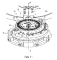
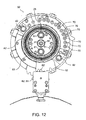
- Figures 11 and 12 represent an embodiment of a twisting device 50.
- the twisting device 50 comprises at least a first 51 and a second body 52 coaxial to one another and extending around a twisting axis Zt-Zt, respectively comprising a first A1 and a second A2 circular array of pockets centred around such an axis Zt-Zt.
- each circular array A1, A2 comprises 72 pockets. It should be observed that in the case in which the slots of the stator have more than two insertion positions P1, P2, the twisting device 50 will comprise more than two arrays of pockets.
- the inner and outer bodies 51, 52 are able to rotate with respect to one another around the twisting axis Zt-Zt to take up at least one insertion (or conductor loading) configuration, in which respective pockets of the first and of the second circular array A1, A2 are radially aligned with one another.
- radial direction we mean a direction perpendicular to and passing through the twisting axis Zt-Zt.
- one or more preformed U-shaped conductors 25 can be inserted into the pockets so that two legs 5 of the aforementioned preformed U-shaped conductors are inserted into a pair of adjacent and radially aligned pockets 8 of the first A1 and of the second A2 circular array.
- the loading of the preformed U-shaped bar conductors 25 inside the twisting device 50 can, for example and without for this reason introducing any limitation, be made in the loading station 31 using an insertion device as for example described in patent US 7,721,413 .
- the preformed U-shaped conductors 25 are for example, and without for this reason introducing any limitation, made through an apparatus and a process as described in patent US 7,480,987 .
- Possible variants of the aforementioned apparatus are described in patent applications No. PCT/IT2010/000160 and No. PCT/IT2010/000187 , not yet published at the filing date of the present application.
- the pockets of the twisting device 50 are made in accordance with the teachings of patent application No. PCT/IT2010/000174 not yet published at the filing date of the present application.
- the twisting device 50, 51 comprises clamping elements 61, 62 that are per sé known, and for this reason not described any further, able to be activated to independently clamp the first 51 and/or the second body 52 to an external reference, for example to the rotary table 36, to prevent it from rotating with respect to such a reference.
- the inner and outer bodies 51, 52 of the twisting device 50 comprise coupling seats 81, 82 suitable for interfacing with respective coupling pins 41, 42 provided in the containment head 40.
- coupling pins 41, 42 it is possible to set in relative rotation the two bodies 51, -52.
- the coupling pins 41, 42 are fixedly connected, respectively, to two portions 43, 44 of the containment head 40 able to be set into relative rotation with respect to one another for example through a pair of servomotors, not shown in the figures.
- an intermediate cylinder 53 suitable for separating the pockets of the first array A1 from the pockets of the second array A2.
- a cylinder for example has a main body in the form of a relatively thin tubular wall 53.
- the twisting device 50 comprises a system for clamping bar conductors comprising at least one sliding clamping element 72, 92 able to be moved in a radial direction with respect to the axial direction Zt-Zt, between an advanced operating position in which it has an end portion 75, 95 that projects inside an associated pocket and a set-back operating position.
- the advanced and set-back operating positions respectively correspond to an operative state clamping the conductor and to an operative state releasing the conductor.
- the set-back and advanced operating positions should be shown respectively in figures 13 and 14 , but since the stroke of the sliding element is relatively short for example equal to 1-3 mm, it is impossible with the scale of drawing to appreciate a difference in position of the sliding clamping element 72, 92 in such figures.
- the clamping system comprises a plurality of sliding clamping elements 72, 92. It should be observed that in the particular example represented in the figures, the plurality of sliding clamping elements 72, 92 comprises at least one sliding clamping element 92 associated with a pocket of the first array A1 and at least one sliding clamping element 72 associated with a pocket of the second array A2.
- the plurality of sliding clamping elements 72, 92 comprises a first plurality 92 of sliding clamping elements associated with pockets of the first array A1 and a second plurality 72 of sliding clamping elements associated with pockets of the second array A2.
- the clamping system comprises a sliding clamping element associated with many pockets of the same array A1, A2.
- the same sliding clamping element 72, 92 when it takes up the advanced position, is able to simultaneously clamp many legs 5 of conductors.
- This embodiment given as an example and not for limiting purposes, is represented in figure 15 in which it can be seen how each of the sliding clamping elements 72, 92 is suitable for cooperating with a pair of adjacent legs 5.
- the clamping system is such as to clamp all of the legs of the special bar conductors during a relative rotation of the two bodies 51, 52.
- FIG 18 an example scheme for loading the conductors inside the pockets of the twisting device 50 is shown, before subjecting the set of bar conductors to the twisting operation in the station 33.
- the outer pockets (array A2) are loaded with legs 5 that form a first continuous arc of circumference (from the arrow F5 to the arrow F6 in the clockwise direction).
- the inner pockets (array A1) are also loaded with legs 5 that form a second continuous circular arc (from the arrow F7 to the arrow F8 in the clockwise direction).
- All of the pockets of the aforementioned first and second arc house legs 5 of preformed U-shaped conductors 25 that have been subjected in the example to pre-twisting of 5°, or more generally to a twisting by a predetermined first pitch.
- Such pre-twisting can, for example, be carried out in the insertion station 31 of the twisting apparatus 30. This pre-twisting, together with the subsequent twisting at the station 33 of all of the conductors inserted in the twisting device 50 makes it possible to obtain the basic conductors of the first and of the second type U1, U2 described above.
- the pockets marked with a square receive legs of special conductors S1, S2, S3.
- the remaining pockets, marked by a circle house legs 5 of preformed U-shaped conductors 25 (which in the example represented are twelve in number) not subjected to any pre-twisting.
- the clamping system of the twisting device 50 is such as to clamp all of the legs of the special conductors S1, S2, S3, and therefore the legs marked in figure 18 with the square, and all of the legs 5 of the basic preformed U-shaped conductors and not subjected to any pre-twisting that belong:
- the intermediate cylinder 53 represents an abutment wall of the pockets of the array A1 and A2 opposite the sliding clamping element 72, 92.
- the clamping system is suitable, in the operative state clamping the conductor, for clamping a leg 5 of the conductor between the abutment wall 53 and the sliding clamping element 72,92.
- the clamping system comprises at least one sliding thrusting member 70, 90 suitable for translating parallel to the twisting axis Zt-Zt and suitable for cooperating with the sliding clamping element 72, 92 to push it into the advanced position.
- the sliding thrusting member 70, 90 comprises at least one first sliding thrusting member 90 operatively associated with the inner body 51 and a second sliding thrusting member 70 operatively associated with the outer body 52.
- a sliding thrusting member 70, 90 cooperates with many sliding clamping elements 72, 92.
- the sliding thrusting member 90 associated with the inner body 51 is operatively coupled with twelve sliding clamping elements 92.
- a respective sliding thrusting member 70 is provided for each of the eleven sliding clamping elements 72 associated with the second body 52.
- the clamping system of the twisting device 50 comprises at least one elastic element 96, like for example one or more helical compression springs, suitable for keeping the sliding clamping element 72, 92 in the set-back position and the sliding thrusting member 70, 90 is such as to push the sliding clamping element 72, 92 into the advanced position in contrast to the action of the elastic element 96.
- elastic element 96 like for example one or more helical compression springs, suitable for keeping the sliding clamping element 72, 92 in the set-back position and the sliding thrusting member 70, 90 is such as to push the sliding clamping element 72, 92 into the advanced position in contrast to the action of the elastic element 96.
- two helical springs 96 are in particular provided, one of which is associated with the sliding clamping element 92 and the other with the sliding thrusting member 90.
- elastic elements 76 with the sliding clamping element 72 and with the thrusting member 70 of the outer body 52.
- the sliding clamping element 72, 92 and the sliding thrusting member 70, 90 are equipped with a first and a second interface wall 73,74 and 93,94 that interfere with one another in abutment, the interface walls being flat and inclined with respect to the axial direction Zt-Zt.
- Such walls are intended to slide on top of one another during a translation of the sliding thrusting member 70, 90 with the purpose of making the sliding clamping element 72, 92 advance.
- such walls form an angle of about 30° with the twisting axis Zt-Zt.
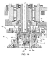
- the twisting apparatus 30 comprises a containment head 40 suitable for being moved axially along the twisting axis Zt-Zt between a rest position ( figure 13 ) and a work position ( figure 14 ) to cooperate with the twisting device 50.
- a head comprises an abutment/containment surface 45 suitable for controlling the deformation of the basic conductors U1, U2 during the twisting operation.
- Such a head can possibly comprise radial grippers 47 for clamping the special conductors S1-S3.
- the head is such as to activate the clamping system of the twisting device 50 automatically and mechanically once the work position has been reached ( figure 14 ).
- the containment head 40 is such as to interfere in abutment with the sliding thrusting member 70, 90 in passing from the rest position to the work position to move in translation the sliding thrusting member 70, 90 and therefore also the sliding clamping member 72, 92.
- an end portion 79, 99 of the thrusting members 70, 90 projects outside of the respective bodies 52, 51 to interfere in abutment, in the work position of the head 40, with respective projecting elements 48, 46 provided in it.
- the end portion 79 is relatively rigid, whereas the projecting abutment element 48 is made from relatively elastic material, for example rubber.
- the abutment element 48 is for example intended to cooperate with many sliding thrusting elements 70, 90, being shaped for example like an arch.
- the abutment element 46 is made from relatively rigid material whereas the projecting end portion 99, for example having a circular shape and trapezoidal section, is made from relatively elastic material, for example rubber.
- the twisting apparatus 30 comprises a device 100 for adjusting the insertion height of selected conductors inside the pockets, the adjustment device 100 being suitable for adjusting the insertion height of selected conductors before the operative clamping state of such conductors is achieved through the clamping system described above.
- the height adjustment device 100 represented comprises at least one pair of height reference blades 101, 102 that are radially aligned and suitable for being inserted into two radially aligned pockets of the first and of the second array A1, A2, respectively.
- the device it is theoretically possible for the device to have, instead of a pair of height reference blades 101, 102, a single height reference blade, for example to bring a preformed conductor with a single leg, like for example a terminal S1, to the correct height.
- a pair of height reference blades 101, 102 a single height reference blade, for example to bring a preformed conductor with a single leg, like for example a terminal S1, to the correct height.
- the insertion of the height reference blades 101, 102 inside the respective pockets on the side of the lower face 50d of the twisting device 50 makes it possible to bring possible conductors to be clamped, that in the steps prior to the twisting operation, due to the clearance between the inner walls of the pockets and the outer walls of the legs 5, have undergone a lowering in height with respect to a desired insertion height, back to a predefined height through the clamping system.
- the height adjustment device 100 comprises a slider 103 to which the height reference blades 101, 102 are fixed and comprises a guide column 104 of the slider 103. Such a guide column 104 is fixed to a support base 105.
- the height adjustment device 100 also comprises linear moving members suitable for controlling the sliding of the slider of the guide, like for example a pneumatic linear actuator 106 comprising a piston connected to the slider 103.
- the height adjustment device 100 makes it possible to bring those conductors, like for example those with a single leg like the phase terminals S1, for which it is particularly critical to maintain their position after insertion into the pocket, back into a correct position.
- the height adjustment device 100 can be provided for the height adjustment device 100 to have a number of pairs of height reference blades 101, 102 such as to bring all of the conductors having legs 5 intended to be clamped by the clamping system described above back to the desired height.
- the twisting device 50 is represented in an operating insertion configuration.
- the twisting device 50 is positioned at the loading station 31.
- the loading of the basic conductors U1, U2 takes place.
- a pre-twisting of these by a predetermined pitch for example equal to one pocket
- the pockets intended to house the legs 5 of the special conductors S1-S3 are left free.
- the rotary table 36 is set in rotation in the clockwise direction to bring the twisting device into the loading station 32 of the special conductors S1-S3. In such a station for example the loading is carried out manually by an operator.
- the rotary table 36 is set in rotation in the clockwise direction to bring the twisting device 50 into the twisting station 33.
- the height adjustment device 100 is actuated making the height reference blades 101, 102 advance towards the twisting device 50.
- the containment head 40 is moved in translation towards the twisting device 50 until, by interference in abutment of the containment head 40 with the sliding thrusting members 70, 90, the operative clamping state of the conductors is achieved.
- the height reference blades 101, 102 are pullet back with respect to the twisting device 50.
- the two bodies 51, 52 are rotated by a predetermined amount, i.e. the actual twisting operation of the head portions is carried out.
- the rotary table 36 is set in rotation in the clockwise direction to bring the twisting device 50 into the station 34 for extracting the conductors and inserting them into a stator core 2.
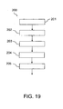
- a twisting method 200 of preformed conductors for bar windings of electric machines has in practice been described, the method 200 comprising the steps of:
- the method 200 comprises, before the clamping step 204, a step 204 of adjusting the insertion height of said at least one conductor for insertion inside the pocket and from the opposite side of said device with respect to a loading side, of a height reference blade 101, 102.
- twisting apparatus described above allows the requirements described above with reference to the prior art to be satisfied.
- the aforementioned apparatus 30 makes it possible to stabilise the position of selected conductors with respect to the twisting device 50 and to obtain a precise twisting and bar windings having conductors having a relatively precise shape.
Landscapes
- Engineering & Computer Science (AREA)
- Manufacturing & Machinery (AREA)
- Power Engineering (AREA)
- Mechanical Engineering (AREA)
- Manufacture Of Motors, Generators (AREA)
- Wire Processing (AREA)
Description
- The present description concerns an apparatus for twisting electrical bar conductors, in particular for bar windings of electrical machines.
- Components of electric machines, such as stators and rotors, are known that comprise electric bar conductors bent and variously connected together so as to make so-called bar windings.
- In particular, the state of the art includes bar windings made through electric bar conductors having an essentially rectangular cross section, where by rectangular we mean both the square section and the "flat" section with which a rectangular-shaped section in which one of the two sides of the section is shorter than the other is generally indicated.
- The aforementioned bar conductors are preformed usually through bending in a 'U' or 'P' shape from straight bar conductors. United States patent
US 7,480,987 describes an example of a method for preforming bar conductors (known in such a document as "hairpin conductors"). The preforming is such as to modify the shape of the straight conductors so that they can be suitably inserted in suitable radially aligned pockets made in a twisting device suitable for deforming the aforementioned preformed conductors after insertion. In practice, the twisting device is used essentially to "spread apart" the legs of the "U" or "P" shape to ensure that two legs of the same conductor, after having extracted it from the twisting device, can subsequently be inserted into the slots of a stator or rotor core radially offset from one another by a predetermined pitch. - The United States patent application published with number
US 2009/0178270 describes a method for twisting preformed bar conductors after their insertion in the pockets of a twisting device: -
US 2476745 A discloses a handling device adapted to transfer shaped conductor segments to a stator. - In order to precisely bend the bar conductors that form a bar winding, there is a great need to stably clamp in position at least some of the aforementioned bar conductors after their insertion in the pockets of the twisting device, for example during the twisting operation. In particular, without for this reason introducing any limitation, there is an especially great need to stably clamp in position at least the bar conductors provided to make the so-called special elements after their insertion in the pockets of the twisting device, for example before the start of the twisting operation and for the entire duration of such an operation.
- The purpose of the present description is to provide a twisting apparatus that is such as to satisfy the requirement outlined above with reference to the prior art.
- Such a purpose is accomplished through a twisting apparatus according to the invention as defined in general in
claim 1 and in the claims dependent upon it in particular embodiments. - A further purpose of the present description is to provide a twisting method according to the invention as defined in the attached claim 13 and it's dependent claim 14.
- Further characteristics and advantages of the present invention will become clearer from the following description of its preferred and not limiting embodiments, in which:
-
figure 1 schematically shows a side view of an embodiment of a stator for an electric machine, comprising a stator core and a stator bar winding; -
figure 2 shows a perspective view of a first type of basic conductor; -
figure 3 shows a perspective view of a second type of basic conductor; -
figure 4 shows a perspective view of a bar conductor suitable for carrying out the function of a phase terminal; -
figure 5 shows a perspective view of a bar conductor suitable for carrying out the function of a jumper; -
figure 6 shows a perspective view of a bar conductor suitable for carrying out the function of neutral or star point; -
figure 7 schematically shows a view from above of a portion of the stator core, in which it is possible to see two slots intended to be filled with respective preformed insulating sheets and bar conductors; -
figure 8 schematically shows a view from above of a portion of the stator core, in which it is possible to see two slots that house respective insulating sheets and bar conductors; -
figure 9 represents a P-shaped preformed bar conductor; -
figure 10 shows a view from above of a twisting apparatus; -
figure 11 shows a perspective view of an embodiment of a twisting device comprised in the twisting apparatus offigure 10 ; -
figure 12 shows a view from above of the twisting device offigure 11 ; -
figure 13 shows a side section view of a portion of the twisting apparatus offigure 10 in which said portion is shown in a first operating configuration; -
figure 14 shows a side section view of the portion of twisting apparatus represented infigure 13 , in which said portion is shown in a second operating configuration; -
figure 15 shows a partial section view of the twisting device offigure 11 ; -
figure 16 shows an enlarged part offigure 13 ; -
figure 17 shows a side section view of a further portion of the twisting apparatus offigure 10 ; -
figure 18 shows a possible filling scheme of the twisting device offigure 11 ; and -
figure 19 shows a block diagram of a twisting process. - In the figures, elements that are the same or similar are indicated with the same reference numerals.
- For the purposes of the present description by "flat" or "square" bar conductor we mean a bar conductor having four substantially flat sides, each joined at adjacent sides, typically by a rounded edge.
- Therefore, the words "flat" or "square" or equivalent words used to describe the cross section of a bar conductor are used in the general sense and must not be interpreted to exclude the fact that such bar conductors have significantly rounded edges that join the substantially flat sides. The expression "flat conductor" should be taken in the sense that the conductor has two opposite sides the distance between which is greater than the distance between the remaining two opposite sides. For the purposes of the present description the expression "rectangular conductor" should be taken as a generalisation of flat conductor and of square conductor, the square conductor being a special case of a rectangular conductor, in which the four sides are of equal dimensions.
- With reference to the attached figures,
reference numeral 1 generically indicates a stator comprising astator core 2. For example, thestator 1 is the stator of an electric machine like for example an electric motor, for example for an electric or hybrid traction vehicle. - It is clear that such a stator can also be used in an electric machine used as a generator or used both to carry out the function of a motor and the function of a generator alternately. In the attached figures just the stator of such an electric machine has been represented since it is considered that the remaining parts of an electric machine or in general of an electric or hybrid traction vehicle are widely known by the man skilled in the art.
- For the sake of simplicity and brevity of description, in this document a rotor will also not be described in detail since it is considered that a man skilled in the art, who knows the structure of a rotor very well, can without any difficulty foresee to apply the teachings of the present description to a rotor.
- In a per sé known way, the
stator core 2 comprises a lamellar tubular main body, for example made from magnetic material, which extends axially (axis Z-Z) between twoopposite faces 3,4, respectively calledinsertion face 3 and welding face 4. - The main body of the
stator core 2 comprises a plurality ofslots 8 that extend axially in the thickness of the main body and that are crossed by bar conductors U1, U2, S1, S2, S3 that as a whole form at least one stator bar winding. In accordance with an embodiment, the bar conductors U1, U2, S1, S2, S3 are surface coated with an insulating layer of insulating material, like for example an insulating enamel. - In accordance with an embodiment, the aforementioned bar conductors U1, U2, S1, S2, S3 are conductors made from copper and are flat rectangular conductors, since they have a pair of opposite faces that are farther apart than the other two opposite faces.
- In accordance with an embodiment, the bar conductors U1, U2, S1, S2, S3 comprise a first plurality of basic conductors U1, U2, and a second plurality of special conductors S1-S3 that comprise for example terminals S1, jumpers S2 or the neutral S3. As known, these bar conductors S1-S3 represent so-called special elements provided to complete the winding. In the present description, the expression "basic conductors" is used exclusively to identify conductors that are not special elements of the type described above, i.e. that are not specifically provided to functionally complete the winding.
- The basic bar conductors U1, U2 of the first plurality have a
bent portion 15, or connection portion, which projects from theinsertion face 3 of thestator core 2 and twolegs 5 thefree end portions 7 of which project from the other face 4 of thestator core 2, i.e. from the welding face 4. Thebent portion 15 is also known in the field as "head portion". In accordance with a non-limiting embodiment between the basic conductors there is a first type of conductors U1 and a second type of conductors U2 that differ from one another mainly for the distance between thelegs 5. As known to a man skilled in the art this difference also involves a certain difference in the overall length of the conductor. - The basic bar conductors U1, U2 are obtained by spreading apart the
legs 5 of apreformed bar conductor 25 shaped like a "U", or like a "P" as for example represented infigure 9 , by a predetermined amount or pitch. Henceforth for the sake of simplicity of description and without for this reason introducing any limitation, the preformed bar conductors shaped like a U or P will be indicated in general as "preformed U-shaped conductors", by U meaning an approximation of the P offigure 9 . - The operation of spreading apart the legs of the preformed U-shaped conductors is generally called twisting, and more specifically twisting of the head portions and the predetermined amount, or pitch, is called "twisting pitch", and more specifically twisting pitch of the head portions. The latter is measured in number of
slots 8. For example, the basic bar conductors of the first type U1 are obtained by twisting of the preformed U-shaped conductor of the same or similar type as the one represented infigure 9 according to a twisting pitch equal to nine slots, whereas the basic bar conductors of the second type U2 are obtained by twisting of the preformed U-shaped conductor of the same or similar type as the one represented infigure 9 according to a twisting pitch equal to eight slots. It is clear that the aforementioned twisting operation of the head portions to spread apart thelegs 5 of the same preformed U-shaped conductor must, after having inserted said preformedconductors 25 subjected to twisting into the stator core, be followed by a twisting of theend portions 7, to allow the welding of such portions required to make the winding. It is also clear that to ensure that the basic conductors U1, U2, after twisting, haveconnection portions 15 arranged at the same height, said basic conductors must be obtained from preformed U-shaped conductors of different length. - The special conductors S1-S3 also comprise at least one
leg 5, abent end portion 7 projecting from the welding face 4 and variously shapedopposite end portions insertion face 3. The shape of the special conductors S1-S3 is also modified in the twisting operation of the head portions. Henceforth for the sake of simplicity we shall refer to the twisting operation of the head portions using the more concise expression "twisting operation". - With reference to
figures 7 and 8 , eachslot 8 of thestator core 2 is crossed by at least two legs of the aforementioned bar conductors U1, U2, S1, S2, S3, and houses at least onesheet 10, or casing 10, made from insulating material. - In accordance with an embodiment, as shown in
figure 7 , in the case in which the bar conductors are flat, the two bar conductors inside the same slot are aligned along their respective short side. - It should be observed that in the particular example represented, each
slot 8 has a first and a second insertion position P1, P2 radially aligned with one another. When thelegs 5 of the bar conductors U1, U2, S1, S2, S3 are inserted inside theslots 8, two circular and concentric arrays oflegs 5 are therefore defined in thestator 1. Clearly, in the case in which eachslot 8 has four insertion positions, four circular and concentric arrays oflegs 5 will be defined and so on. -
Figure 10 shows an example of a twistingapparatus 30, comprising a rotary table 36 suitable for moving atwisting device 50 between different work stations, and in particular between a loadingstation 31 of preformed basic conductors U1, U2, asubsequent loading station 32 of the special conductors S1-S3, a twistingstation 33 and astation 34 for extracting the conductors from the twistingdevice 50 and for loading into astator core 2. The twistingapparatus 30 at the twistingstation 33 comprises acontainment head 40 suitable for cooperating with the twistingdevice 50. -
Figures 11 and12 represent an embodiment of a twistingdevice 50. The twistingdevice 50 comprises at least a first 51 and asecond body 52 coaxial to one another and extending around a twisting axis Zt-Zt, respectively comprising a first A1 and a second A2 circular array of pockets centred around such an axis Zt-Zt. In the particular example indicated, without for this reason introducing any limitation, each circular array A1, A2 comprises 72 pockets. It should be observed that in the case in which the slots of the stator have more than two insertion positions P1, P2, the twistingdevice 50 will comprise more than two arrays of pockets. Henceforth we shall refer to the first and to the second body respectively with the expressionsinner body 51 andouter body 52. - The inner and
outer bodies U-shaped conductors 25 can be inserted into the pockets so that twolegs 5 of the aforementioned preformed U-shaped conductors are inserted into a pair of adjacent and radially alignedpockets 8 of the first A1 and of the second A2 circular array. - In accordance with an embodiment the loading of the preformed
U-shaped bar conductors 25 inside the twistingdevice 50 can, for example and without for this reason introducing any limitation, be made in theloading station 31 using an insertion device as for example described in patentUS 7,721,413 . In accordance with a possible embodiment the preformedU-shaped conductors 25 are for example, and without for this reason introducing any limitation, made through an apparatus and a process as described in patentUS 7,480,987 . Possible variants of the aforementioned apparatus are described in patent applications No.PCT/IT2010/000160 PCT/IT2010/000187 device 50 are made in accordance with the teachings of patent application No.PCT/IT2010/000174 - In accordance with an embodiment, the twisting
device elements 61, 62 that are per sé known, and for this reason not described any further, able to be activated to independently clamp the first 51 and/or thesecond body 52 to an external reference, for example to the rotary table 36, to prevent it from rotating with respect to such a reference. - In accordance with an embodiment, the inner and
outer bodies device 50 comprisecoupling seats containment head 40. Through such coupling pins 41, 42 it is possible to set in relative rotation the twobodies 51, -52. For example the coupling pins 41, 42 are fixedly connected, respectively, to twoportions containment head 40 able to be set into relative rotation with respect to one another for example through a pair of servomotors, not shown in the figures. - In accordance with an embodiment, between the two
bodies intermediate cylinder 53 suitable for separating the pockets of the first array A1 from the pockets of the second array A2. Such a cylinder for example has a main body in the form of a relatively thintubular wall 53. - The twisting
device 50 comprises a system for clamping bar conductors comprising at least one slidingclamping element end portion figures 13 and14 , but since the stroke of the sliding element is relatively short for example equal to 1-3 mm, it is impossible with the scale of drawing to appreciate a difference in position of the sliding clampingelement - In accordance with an embodiment, like in the example represented in the figures, the clamping system comprises a plurality of sliding
clamping elements clamping elements clamping element 92 associated with a pocket of the first array A1 and at least one slidingclamping element 72 associated with a pocket of the second array A2. - In accordance with an embodiment, the plurality of sliding
clamping elements first plurality 92 of sliding clamping elements associated with pockets of the first array A1 and asecond plurality 72 of sliding clamping elements associated with pockets of the second array A2. - In accordance with an embodiment, it is possible that the clamping system comprises a sliding clamping element associated with many pockets of the same array A1, A2. In this way, the same sliding clamping
element many legs 5 of conductors. This embodiment, given as an example and not for limiting purposes, is represented infigure 15 in which it can be seen how each of the slidingclamping elements adjacent legs 5. - In accordance with an embodiment, the clamping system is such as to clamp all of the legs of the special bar conductors during a relative rotation of the two
bodies figure 18 an example scheme for loading the conductors inside the pockets of the twistingdevice 50 is shown, before subjecting the set of bar conductors to the twisting operation in thestation 33. - As can be appreciated, the outer pockets (array A2) are loaded with
legs 5 that form a first continuous arc of circumference (from the arrow F5 to the arrow F6 in the clockwise direction). The inner pockets (array A1) are also loaded withlegs 5 that form a second continuous circular arc (from the arrow F7 to the arrow F8 in the clockwise direction). All of the pockets of the aforementioned first and secondarc house legs 5 of preformedU-shaped conductors 25 that have been subjected in the example to pre-twisting of 5°, or more generally to a twisting by a predetermined first pitch. Such pre-twisting can, for example, be carried out in theinsertion station 31 of the twistingapparatus 30. This pre-twisting, together with the subsequent twisting at thestation 33 of all of the conductors inserted in the twistingdevice 50 makes it possible to obtain the basic conductors of the first and of the second type U1, U2 described above. - Again with reference to
figure 18 , the pockets marked with a square receive legs of special conductors S1, S2, S3. The remaining pockets, marked by a circle,house legs 5 of preformed U-shaped conductors 25 (which in the example represented are twelve in number) not subjected to any pre-twisting. With reference tofigure 15 , in the embodiment used as an example, the clamping system of the twistingdevice 50 is such as to clamp all of the legs of the special conductors S1, S2, S3, and therefore the legs marked infigure 18 with the square, and all of thelegs 5 of the basic preformed U-shaped conductors and not subjected to any pre-twisting that belong: - to the arc of the inner array A1 comprised between the leg Bi1 and the leg Bi18 inclusive, starting from Bi1 and rotating clockwise; and
- to the arc of the outer array A2 comprised between the leg Be1 and the leg Be18 inclusive, starting from Be1 and rotating clockwise.
- Again with reference to
figure 15 , it can be appreciated how the clamping system can be designed, without for this reason introducing any limitation, to clamp further legs of conductors not belonging to the arcs just defined above for example arranged adjacent to such arcs. - With reference to
figure 16 , it should be observed how theintermediate cylinder 53 represents an abutment wall of the pockets of the array A1 and A2 opposite the sliding clampingelement leg 5 of the conductor between theabutment wall 53 and the sliding clampingelement - In accordance with an embodiment, the clamping system comprises at least one sliding thrusting
member element - In the particular example described, the sliding thrusting
member member 90 operatively associated with theinner body 51 and a second sliding thrustingmember 70 operatively associated with theouter body 52. - In accordance with a preferred and non-limiting embodiment, it is possible to that a sliding thrusting
member clamping elements figures 13-15 , it should be observed that the sliding thrustingmember 90 associated with theinner body 51 is operatively coupled with twelve slidingclamping elements 92. However, for each of the eleven slidingclamping elements 72 associated with thesecond body 52, a respective sliding thrustingmember 70 is provided. The clamping system of the twistingdevice 50 comprises at least oneelastic element 96, like for example one or more helical compression springs, suitable for keeping the sliding clampingelement member element elastic element 96. With reference tofigure 13 , it can be seen how in the example represented twohelical springs 96 are in particular provided, one of which is associated with the sliding clampingelement 92 and the other with the sliding thrustingmember 90. Clearly, with reference tofigure 16 , in a totally analogous way it is possible to associateelastic elements 76 with the sliding clampingelement 72 and with the thrustingmember 70 of theouter body 52. - In accordance with an embodiment, the sliding clamping
element member member element - With reference to
figures 13 and14 in accordance with an embodiment, the twistingapparatus 30 comprises acontainment head 40 suitable for being moved axially along the twisting axis Zt-Zt between a rest position (figure 13 ) and a work position (figure 14 ) to cooperate with the twistingdevice 50. Such a head comprises an abutment/containment surface 45 suitable for controlling the deformation of the basic conductors U1, U2 during the twisting operation. Such a head can possibly compriseradial grippers 47 for clamping the special conductors S1-S3. - In accordance with an embodiment, the head is such as to activate the clamping system of the twisting
device 50 automatically and mechanically once the work position has been reached (figure 14 ). - In accordance with a particular embodiment, the
containment head 40 is such as to interfere in abutment with the sliding thrustingmember member member end portion members respective bodies head 40, with respective projectingelements 48, 46 provided in it. For example, theend portion 79 is relatively rigid, whereas the projecting abutment element 48 is made from relatively elastic material, for example rubber. In accordance with an embodiment, the abutment element 48 is for example intended to cooperate with many sliding thrustingelements figure 13 , in accordance with an embodiment, theabutment element 46 is made from relatively rigid material whereas the projectingend portion 99, for example having a circular shape and trapezoidal section, is made from relatively elastic material, for example rubber. - In accordance with a further embodiment, the twisting
apparatus 30 comprises adevice 100 for adjusting the insertion height of selected conductors inside the pockets, theadjustment device 100 being suitable for adjusting the insertion height of selected conductors before the operative clamping state of such conductors is achieved through the clamping system described above. - The
height adjustment device 100 represented comprises at least one pair ofheight reference blades height reference blades - The insertion of the
height reference blades lower face 50d of the twistingdevice 50 makes it possible to bring possible conductors to be clamped, that in the steps prior to the twisting operation, due to the clearance between the inner walls of the pockets and the outer walls of thelegs 5, have undergone a lowering in height with respect to a desired insertion height, back to a predefined height through the clamping system. - The
height adjustment device 100 comprises aslider 103 to which theheight reference blades guide column 104 of theslider 103. Such aguide column 104 is fixed to asupport base 105. Theheight adjustment device 100 also comprises linear moving members suitable for controlling the sliding of the slider of the guide, like for example a pneumaticlinear actuator 106 comprising a piston connected to theslider 103. Theheight adjustment device 100 makes it possible to bring those conductors, like for example those with a single leg like the phase terminals S1, for which it is particularly critical to maintain their position after insertion into the pocket, back into a correct position. Clearly, it can be provided for theheight adjustment device 100 to have a number of pairs ofheight reference blades conductors having legs 5 intended to be clamped by the clamping system described above back to the desired height. - Hereafter an example of operation of a twisting
apparatus 30 as described above will be described. - In
figure 11 thetwisting device 50 is represented in an operating insertion configuration. In such a configuration the twistingdevice 50 is positioned at theloading station 31. At such a station the loading of the basic conductors U1, U2 takes place. In particular it takes place first the loading of the preformed conductors of the first type U1, a pre-twisting of these by a predetermined pitch (for example equal to one pocket) and the subsequent loading of the preformed conductors of the second type U2. At the end of the loading the pockets intended to house thelegs 5 of the special conductors S1-S3 are left free. - At the end of the loading step of the basic conductors U1, U2 described above, the rotary table 36 is set in rotation in the clockwise direction to bring the twisting device into the
loading station 32 of the special conductors S1-S3. In such a station for example the loading is carried out manually by an operator. - After the loading of the special conductors S1-S3, the rotary table 36 is set in rotation in the clockwise direction to bring the
twisting device 50 into the twistingstation 33. If provided, theheight adjustment device 100 is actuated making theheight reference blades device 50. Keeping the blades in position, thecontainment head 40 is moved in translation towards the twistingdevice 50 until, by interference in abutment of thecontainment head 40 with the sliding thrustingmembers height reference blades device 50. Thereafter, the twobodies twisting device 50 into thestation 34 for extracting the conductors and inserting them into astator core 2. - With reference to
figure 19 , based on the operation illustrated above of the twisting apparatus and also based on the description given of the twisting apparatus, it can be seen that atwisting method 200 of preformed conductors for bar windings of electric machines has in practice been described, themethod 200 comprising the steps of: - a) providing 201 a twisting
apparatus 30 comprising a twistingdevice 50 having at least a first 51 and a second 52 body coaxial to one another and extending around a twisting axis Zt-Zt and respectively comprising a first and a second circular array A1, A2 of pockets with centre on such an axis; - b) providing 202 a plurality of preformed bar conductors having at least one
leg 5 and inserting the legs of said' plurality of conductors into respective pockets; - c) clamping 204 at least one of said legs inside a respective pocket by actuating a respective clamping element suitable for interfering in abutment with a wall portion of said leg inside such a pocket;
- d) setting in
relative rotation 205 the first and the second body. - In accordance with an embodiment, the
method 200, comprises, before the clampingstep 204, astep 204 of adjusting the insertion height of said at least one conductor for insertion inside the pocket and from the opposite side of said device with respect to a loading side, of aheight reference blade - As can be appreciated from what has been described the twisting apparatus described above allows the requirements described above with reference to the prior art to be satisfied.
- Indeed, it should be observed that the
aforementioned apparatus 30 makes it possible to stabilise the position of selected conductors with respect to the twistingdevice 50 and to obtain a precise twisting and bar windings having conductors having a relatively precise shape.
Claims (14)
- Apparatus (30) for twisting preformed bar conductors (25) for bar windings of electric machines, each of said conductors (25) comprising one or more legs (5), the twisting apparatus (30) comprising a twisting device (50) having at least a first (51) and a second body (52) coaxial to one another and extending around a twisting axis (Zt-Zt) defining an axial direction and comprising respectively a first (A1) and second (A2) circular array of pockets with centre on such an axis (Zt-Zt), the pockets being suitable for receiving legs (5) of said preformed bar conductors, said bodies (51, 52) being able to rotate relative to one another around the twisting axis (Zt-Zt),
characterised in that
the twisting device (50) comprises a system for clamping bar conductors comprising at least one sliding clamping element (72, 92) able to be moved in a radial direction with respect to the axial direction (Zt-Zt) to take up an advanced operating position in which it has an end portion (73, 74, 93, 94) that projects inside an associated pocket and a set-back operating position, the advanced and set-back operating positions corresponding, respectively, to an operative state clamping the conductor and an operative state releasing the conductor. - Twisting apparatus (30) according to claim 1, wherein the clamping system comprises a plurality of said sliding clamping elements (72, 92).
- Twisting apparatus (30) according to claim 2, wherein the plurality of sliding clamping elements (72, 92) comprises at least one clamping element (92) associated with a pocket of the first array (A1) and at least one clamping element (72) associated with a pocket of the second array (A2).
- Twisting apparatus (30) according to any one of the previous claims, wherein the preformed bar conductors comprise a set of basic conductors (U1, U2) and a set of special conductors (S1-S3) to complete the winding, and wherein the sliding clamping elements (72, 92) are suitable for cooperating with the set of special conductors to clamp them during a relative rotation between the first and second body.
- Twisting apparatus (30) according to claim 1, wherein said associated pocket comprises an abutment wall (53) opposite the sliding clamping element and wherein the clamping system is suitable, in the operative state clamping the conductor, for clamping said leg (5) between the abutment wall (53) and the sliding clamping element (72, 92).
- Twisting apparatus (30) according to any one of the previous claims, wherein the twisting device (50) comprises at least one sliding thrusting member (70, 90) able to slide parallel to said axial direction (Zt-Zt) and suitable for cooperating with the sliding clamping element (72, 92) to push it into said advanced position.
- Twisting apparatus (30) according to claim 6, wherein the sliding thrusting member (70, 90) comprises at least one first sliding thrusting member operatively associated with the first body (51) and a second sliding thrusting member associated with the second body (52).
- Twisting apparatus (30) according to claims 6 or 7, wherein the clamping system comprises at least one elastic element (96) suitable for keeping the sliding clamping element (72, 92) in the set-back position and wherein the sliding thrusting member (70, 90) is such as to push the sliding clamping element into the advanced position in contrast to the action of said elastic element.
- Twisting apparatus (30) according to any one of claims 7 to 9, wherein the sliding clamping element (72, 92) and the sliding thrusting member (70,90) are respectively equipped with a first and a second interface wall that interfere with one another in abutment, said interface walls being flat and inclined with respect to said axial direction (Zt-Zt).
- Twisting apparatus (30) according to any one of the previous claims, wherein the apparatus comprises a containment head (40) suitable for being moved in said axial direction (Zt-Zt) between a rest position and a work position to cooperate with the twisting device (50) and said bar conductors, said head (40) being such as to activate the clamping system automatically and mechanically once the work position has been reached.
- Twisting apparatus (30) according to claim 10 and any one of claims 6 to 9, wherein the containment head (40) is such as to interfere in abutment with the sliding thrusting member (70,90) in passing from the rest position to the work position to move the sliding thrusting member (70, 90) in translation.
- Twisting apparatus (30) according to any one of the previous claims, comprising a device (100) for adjusting the insertion height of said conductor inside said pocket, the adjustment device (100) being suitable for adjusting the insertion height of said conductor before the operative state clamping the conductor is achieved.
- Method (200) for twisting preformed conductors for bar windings of electric machines, the method (200) comprising the steps of:a) providing (201) a twisting apparatus (30) comprising a twisting device (50) having at least a first (51) and a second (52) body coaxial to one another and extending around a twisting axis (Zt-Zt) and respectively comprising a first and a second circular array (A1, A2) of pockets with centre on such an axis;b) providing (202) a plurality of preformed bar conductors having at least one leg (5) and inserting the legs of said plurality of conductors into respective pockets;c) clamping (204) at least one of said legs inside a respective pocket by actuating a respective clamping element (72, 92) suitable for interfering in abutment with a wall portion of said leg inside such a pocket;d) setting in relative rotation (205) the first and the second body.
- Twisting method (200) according to claim 13, comprising before the clamping step (204), a step of adjusting (204) the insertion height of said at least one conductor for insertion inside the pocket and on the opposite side of said device with respect to a loading side, of a height reference blade (101, 102).
Applications Claiming Priority (1)
| Application Number | Priority Date | Filing Date | Title |
|---|---|---|---|
| PCT/IT2010/000338 WO2012014233A1 (en) | 2010-07-28 | 2010-07-28 | Apparatus for twisting electrical bar conductors, in particular for bar windings of electrical machines, with conductor' s clamping system |
Publications (2)
| Publication Number | Publication Date |
|---|---|
| EP2599194A1 EP2599194A1 (en) | 2013-06-05 |
| EP2599194B1 true EP2599194B1 (en) | 2014-12-03 |
Family
ID=44022017
Family Applications (1)
| Application Number | Title | Priority Date | Filing Date |
|---|---|---|---|
| EP10763460.2A Active EP2599194B1 (en) | 2010-07-28 | 2010-07-28 | Apparatus for twisting electrical bar conductors, in particular for bar windings of electrical machines, with conductor' s clamping system |
Country Status (6)
| Country | Link |
|---|---|
| US (1) | US8661868B2 (en) |
| EP (1) | EP2599194B1 (en) |
| CN (1) | CN103098355B (en) |
| BR (1) | BR112013002045B1 (en) |
| ES (1) | ES2531642T3 (en) |
| WO (1) | WO2012014233A1 (en) |
Cited By (2)
| Publication number | Priority date | Publication date | Assignee | Title |
|---|---|---|---|---|
| WO2017045940A1 (en) * | 2015-09-18 | 2017-03-23 | Continental Automotive Gmbh | Method and two-part tool arrangement for producing a stator for an electrical machine |
| WO2020176916A1 (en) * | 2019-03-01 | 2020-09-10 | Miba Automation Systems Ges.M.B.H. | Method and device for forming a conductor stack and inserting the same into a lamination stack |
Families Citing this family (16)
| Publication number | Priority date | Publication date | Assignee | Title |
|---|---|---|---|---|
| WO2012093413A1 (en) * | 2011-01-04 | 2012-07-12 | Tecnomatic S.P.A. | Method and fixture for twisting end portions of bar conductors, in particular for bar windings of electric machines |
| JP5705287B2 (en) * | 2013-09-18 | 2015-04-22 | 本田技研工業株式会社 | Arrangement apparatus and arrangement method |
| CN103545999B (en) * | 2013-10-31 | 2016-01-13 | 长沙友佳实业有限公司 | Tension-torsion head shaped device is split in the overall doubling of a kind of motor rotor U wire |
| CN103795198B (en) * | 2014-03-05 | 2017-04-26 | 王九龙 | Coil winding machine with four U-shaped parts |
| CN103986287B (en) * | 2014-06-04 | 2016-05-04 | 济南科亚电子科技有限公司 | A kind of bracing wire mould |
| ITBO20150189A1 (en) * | 2015-04-16 | 2016-10-16 | Magneti Marelli Spa | METHOD OF CONSTRUCTION OF AN ELECTRIC MACHINE WITH A STATORIC WINDING WITH RIGID BARS |
| DE102016221355A1 (en) | 2016-10-28 | 2018-05-03 | Thyssenkrupp Ag | Positioning device for positioning copper rods and methods |
| CN106655656B (en) * | 2016-12-29 | 2023-02-24 | 重庆市爱华机电有限公司双福分公司 | Flat copper wire twisting mechanism for armature winding |
| DE102017004538A1 (en) * | 2017-05-11 | 2018-11-15 | Gehring E-Tech Gmbh | Method and device for forming U-shaped electrical conductors |
| CN111164857B (en) * | 2017-06-20 | 2022-11-01 | 格劳博-沃克有限责任两合公司 | Method and device for inserting electrical conductors in machine parts of electrical machines |
| CN108110973B (en) * | 2018-01-31 | 2024-08-23 | 捷云智能装备(苏州)有限公司 | Hairpin conductor assembly mechanism and assembly method |
| EP3853982A1 (en) * | 2018-09-17 | 2021-07-28 | Tecnomatic S.p.A. | Apparatus and process for deforming conductors protruding from a side of a stator or of a rotor of an electric machine |
| DE102019219481A1 (en) * | 2019-12-12 | 2021-06-17 | Robert Bosch Gmbh | Tool for separating and setting wire ends of a winding as well as a method for producing a winding |
| CN111266825A (en) * | 2020-03-27 | 2020-06-12 | 深圳市龙德奥奇自动化系统有限公司 | Brush equipment with prevent taking up function |
| CN111982681B (en) * | 2020-08-13 | 2023-11-24 | 天津精达漆包线有限公司 | Electromagnetic wire torsion device, bending test system and bending test method |
| KR20230014443A (en) * | 2021-07-21 | 2023-01-30 | 현대자동차주식회사 | Hairpin alignment device for a hairpin winding motor and a hairpin alignment method using the same |
Family Cites Families (14)
| Publication number | Priority date | Publication date | Assignee | Title |
|---|---|---|---|---|
| US2476744A (en) * | 1946-09-11 | 1949-07-19 | Leece Neville Co | Coil shaping apparatus |
| US2476745A (en) | 1946-09-11 | 1949-07-19 | Leece Neville Co | Device for gripping, lifting, and handling an annular group of articles such as electrical coils |
| JP3738733B2 (en) * | 2002-01-18 | 2006-01-25 | 株式会社デンソー | Stator for rotating electrical machine for vehicle and method for manufacturing the same |
| JP3775349B2 (en) * | 2002-06-03 | 2006-05-17 | 株式会社デンソー | Method of manufacturing stator winding of rotating electrical machine, winding structure, and method of manufacturing winding |
| JP3960313B2 (en) * | 2004-01-30 | 2007-08-15 | 株式会社デンソー | Coil forming apparatus and coil forming method |
| US7805825B2 (en) | 2007-03-22 | 2010-10-05 | Tecnomatic S.P.A. | Method for forming motor winding conductors |
| US7480987B1 (en) | 2007-03-22 | 2009-01-27 | Tecnomatic, S.P.A. | Method for pre-forming conductors for motor rotors and stators |
| US7941910B2 (en) * | 2007-03-22 | 2011-05-17 | Tecnomatic S.P.A. | Method for removing winding conductors from a twisting machine and placing them in a rotor stator stack |
| US7721413B2 (en) | 2007-03-22 | 2010-05-25 | Tecnomatic, S.P.A. | Method for inserting of preformed hairpin conductors into a rotor or stator |
| US8215000B2 (en) * | 2007-07-20 | 2012-07-10 | Tecnomatic, S.P.A. | Methods for twisting rotor and stator ends |
| JP5227682B2 (en) * | 2008-07-22 | 2013-07-03 | 本田技研工業株式会社 | Stator manufacturing equipment |
| WO2011128919A1 (en) | 2010-04-14 | 2011-10-20 | Tecnomatic S.P.A. | Apparatus and method for pre-forming electrical bar conductors, in particular for bar windings of electrical machines |
| MX2012011177A (en) | 2010-04-23 | 2012-11-23 | Tecnomatic Spa | Twisting device adapted to simultaneously twist a plurality of electric bar conductors for making a stator or rotor winding for an electric machine and an extractor assembly suitable for cooperating with said twisting device. |
| US8793864B2 (en) | 2010-04-28 | 2014-08-05 | Tecnomatic S.P.A. | Apparatus for stripping electrical bar conductors |
-
2010
- 2010-07-28 ES ES10763460.2T patent/ES2531642T3/en active Active
- 2010-07-28 WO PCT/IT2010/000338 patent/WO2012014233A1/en active Application Filing
- 2010-07-28 EP EP10763460.2A patent/EP2599194B1/en active Active
- 2010-07-28 US US13/387,733 patent/US8661868B2/en active Active
- 2010-07-28 BR BR112013002045-8A patent/BR112013002045B1/en active IP Right Grant
- 2010-07-28 CN CN201080068300.3A patent/CN103098355B/en active Active
Cited By (3)
| Publication number | Priority date | Publication date | Assignee | Title |
|---|---|---|---|---|
| WO2017045940A1 (en) * | 2015-09-18 | 2017-03-23 | Continental Automotive Gmbh | Method and two-part tool arrangement for producing a stator for an electrical machine |
| WO2020176916A1 (en) * | 2019-03-01 | 2020-09-10 | Miba Automation Systems Ges.M.B.H. | Method and device for forming a conductor stack and inserting the same into a lamination stack |
| AT522207A1 (en) * | 2019-03-01 | 2020-09-15 | Miba Automation Systems Ges M B H | Method and device for forming a conductor package and inserting it into a laminated core |
Also Published As
| Publication number | Publication date |
|---|---|
| US8661868B2 (en) | 2014-03-04 |
| EP2599194A1 (en) | 2013-06-05 |
| CN103098355B (en) | 2015-09-30 |
| BR112013002045B1 (en) | 2020-03-31 |
| CN103098355A (en) | 2013-05-08 |
| BR112013002045A2 (en) | 2017-10-03 |
| US20130118222A1 (en) | 2013-05-16 |
| WO2012014233A1 (en) | 2012-02-02 |
| ES2531642T3 (en) | 2015-03-18 |
Similar Documents
| Publication | Publication Date | Title |
|---|---|---|
| EP2599194B1 (en) | Apparatus for twisting electrical bar conductors, in particular for bar windings of electrical machines, with conductor' s clamping system | |
| US8726493B2 (en) | Clamping system of special conductors for a stator or rotor bar winding for an electric machine | |
| EP2665158B1 (en) | Stator or rotor of an electrical machine | |
| EP2661801B1 (en) | Method and fixture for twisting end portions of bar conductors, in particular for bar windings of electric machines | |
| CN111865012B (en) | Conductor forming device and method for manufacturing wave winding coil | |
| EP3142235A1 (en) | Stator-manufacturing method and stator | |
| US20120319523A1 (en) | Motor, and motor production method | |
| CN111864948B (en) | Alignment device and method of manufacturing alignment coil | |
| CN113196633B (en) | Device and method for pulling and twisting | |
| KR102272772B1 (en) | Wire assembly for rotary electric machine and corresponding method to obtain the wire assmebly | |
| CN111201700B (en) | Method for producing semi-finished products for stators and device for producing semi-finished products for stators | |
| US11509200B2 (en) | Process for making a continuous bar winding for an electric machine | |
| US20200195102A1 (en) | Method and device for holding a laminated core in position together with conductor elements received therein | |
| CN111434016A (en) | Coil forming apparatus and coil forming method | |
| US20220360150A1 (en) | Method for producing a coil winding for insertion into radially open slots of stators or rotors of electrical machines | |
| JP5177512B2 (en) | Assembly method of split core type stator of inner rotor type rotating electrical machine | |
| CN112262520A (en) | Device and method for deforming a conductor projecting from one side of a stator or rotor of an electric machine | |
| CN110268609A (en) | The forming method of coil and the manufacturing method of stator | |
| CN116391315A (en) | Apparatus and method for assembling hairpin windings | |
| ITRM20100420A1 (en) | APPARATUS OF TURNING ELECTRIC BAR CONDUCTORS, IN PARTICULAR FOR BAR WINDOWS OF ELECTRIC MACHINES, WITH LOCKING SYSTEM OF THE CONDUCTORS | |
| JP6790761B2 (en) | Manufacturing method of rotary electric machine |
Legal Events
| Date | Code | Title | Description |
|---|---|---|---|
| PUAI | Public reference made under article 153(3) epc to a published international application that has entered the european phase |
Free format text: ORIGINAL CODE: 0009012 |
|
| 17P | Request for examination filed |
Effective date: 20130130 |
|
| AK | Designated contracting states |
Kind code of ref document: A1 Designated state(s): AL AT BE BG CH CY CZ DE DK EE ES FI FR GB GR HR HU IE IS IT LI LT LU LV MC MK MT NL NO PL PT RO SE SI SK SM TR |
|
| DAX | Request for extension of the european patent (deleted) | ||
| GRAP | Despatch of communication of intention to grant a patent |
Free format text: ORIGINAL CODE: EPIDOSNIGR1 |
|
| INTG | Intention to grant announced |
Effective date: 20140922 |
|
| GRAS | Grant fee paid |
Free format text: ORIGINAL CODE: EPIDOSNIGR3 |
|
| GRAA | (expected) grant |
Free format text: ORIGINAL CODE: 0009210 |
|
| AK | Designated contracting states |
Kind code of ref document: B1 Designated state(s): AL AT BE BG CH CY CZ DE DK EE ES FI FR GB GR HR HU IE IS IT LI LT LU LV MC MK MT NL NO PL PT RO SE SI SK SM TR |
|
| REG | Reference to a national code |
Ref country code: GB Ref legal event code: FG4D |
|
| REG | Reference to a national code |
Ref country code: AT Ref legal event code: REF Ref document number: 699865 Country of ref document: AT Kind code of ref document: T Effective date: 20141215 Ref country code: CH Ref legal event code: EP |
|
| REG | Reference to a national code |
Ref country code: IE Ref legal event code: FG4D |
|
| REG | Reference to a national code |
Ref country code: DE Ref legal event code: R096 Ref document number: 602010020746 Country of ref document: DE Effective date: 20150115 |
|
| REG | Reference to a national code |
Ref country code: ES Ref legal event code: FG2A Ref document number: 2531642 Country of ref document: ES Kind code of ref document: T3 Effective date: 20150318 |
|
| REG | Reference to a national code |
Ref country code: NL Ref legal event code: VDEP Effective date: 20141203 |
|
| REG | Reference to a national code |
Ref country code: AT Ref legal event code: MK05 Ref document number: 699865 Country of ref document: AT Kind code of ref document: T Effective date: 20141203 |
|
| PG25 | Lapsed in a contracting state [announced via postgrant information from national office to epo] |
Ref country code: LT Free format text: LAPSE BECAUSE OF FAILURE TO SUBMIT A TRANSLATION OF THE DESCRIPTION OR TO PAY THE FEE WITHIN THE PRESCRIBED TIME-LIMIT Effective date: 20141203 Ref country code: NO Free format text: LAPSE BECAUSE OF FAILURE TO SUBMIT A TRANSLATION OF THE DESCRIPTION OR TO PAY THE FEE WITHIN THE PRESCRIBED TIME-LIMIT Effective date: 20150303 Ref country code: FI Free format text: LAPSE BECAUSE OF FAILURE TO SUBMIT A TRANSLATION OF THE DESCRIPTION OR TO PAY THE FEE WITHIN THE PRESCRIBED TIME-LIMIT Effective date: 20141203 Ref country code: NL Free format text: LAPSE BECAUSE OF FAILURE TO SUBMIT A TRANSLATION OF THE DESCRIPTION OR TO PAY THE FEE WITHIN THE PRESCRIBED TIME-LIMIT Effective date: 20141203 |
|
| REG | Reference to a national code |
Ref country code: LT Ref legal event code: MG4D |
|
| PG25 | Lapsed in a contracting state [announced via postgrant information from national office to epo] |
Ref country code: LV Free format text: LAPSE BECAUSE OF FAILURE TO SUBMIT A TRANSLATION OF THE DESCRIPTION OR TO PAY THE FEE WITHIN THE PRESCRIBED TIME-LIMIT Effective date: 20141203 Ref country code: CY Free format text: LAPSE BECAUSE OF FAILURE TO SUBMIT A TRANSLATION OF THE DESCRIPTION OR TO PAY THE FEE WITHIN THE PRESCRIBED TIME-LIMIT Effective date: 20141203 Ref country code: HR Free format text: LAPSE BECAUSE OF FAILURE TO SUBMIT A TRANSLATION OF THE DESCRIPTION OR TO PAY THE FEE WITHIN THE PRESCRIBED TIME-LIMIT Effective date: 20141203 Ref country code: GR Free format text: LAPSE BECAUSE OF FAILURE TO SUBMIT A TRANSLATION OF THE DESCRIPTION OR TO PAY THE FEE WITHIN THE PRESCRIBED TIME-LIMIT Effective date: 20150304 Ref country code: AT Free format text: LAPSE BECAUSE OF FAILURE TO SUBMIT A TRANSLATION OF THE DESCRIPTION OR TO PAY THE FEE WITHIN THE PRESCRIBED TIME-LIMIT Effective date: 20141203 Ref country code: SE Free format text: LAPSE BECAUSE OF FAILURE TO SUBMIT A TRANSLATION OF THE DESCRIPTION OR TO PAY THE FEE WITHIN THE PRESCRIBED TIME-LIMIT Effective date: 20141203 |
|
| PG25 | Lapsed in a contracting state [announced via postgrant information from national office to epo] |
Ref country code: CZ Free format text: LAPSE BECAUSE OF FAILURE TO SUBMIT A TRANSLATION OF THE DESCRIPTION OR TO PAY THE FEE WITHIN THE PRESCRIBED TIME-LIMIT Effective date: 20141203 Ref country code: EE Free format text: LAPSE BECAUSE OF FAILURE TO SUBMIT A TRANSLATION OF THE DESCRIPTION OR TO PAY THE FEE WITHIN THE PRESCRIBED TIME-LIMIT Effective date: 20141203 Ref country code: PT Free format text: LAPSE BECAUSE OF FAILURE TO SUBMIT A TRANSLATION OF THE DESCRIPTION OR TO PAY THE FEE WITHIN THE PRESCRIBED TIME-LIMIT Effective date: 20150403 Ref country code: SK Free format text: LAPSE BECAUSE OF FAILURE TO SUBMIT A TRANSLATION OF THE DESCRIPTION OR TO PAY THE FEE WITHIN THE PRESCRIBED TIME-LIMIT Effective date: 20141203 Ref country code: RO Free format text: LAPSE BECAUSE OF FAILURE TO SUBMIT A TRANSLATION OF THE DESCRIPTION OR TO PAY THE FEE WITHIN THE PRESCRIBED TIME-LIMIT Effective date: 20141203 |
|
| PG25 | Lapsed in a contracting state [announced via postgrant information from national office to epo] |
Ref country code: IS Free format text: LAPSE BECAUSE OF FAILURE TO SUBMIT A TRANSLATION OF THE DESCRIPTION OR TO PAY THE FEE WITHIN THE PRESCRIBED TIME-LIMIT Effective date: 20150403 Ref country code: PL Free format text: LAPSE BECAUSE OF FAILURE TO SUBMIT A TRANSLATION OF THE DESCRIPTION OR TO PAY THE FEE WITHIN THE PRESCRIBED TIME-LIMIT Effective date: 20141203 |
|
| REG | Reference to a national code |
Ref country code: DE Ref legal event code: R097 Ref document number: 602010020746 Country of ref document: DE |
|
| PLBE | No opposition filed within time limit |
Free format text: ORIGINAL CODE: 0009261 |
|
| STAA | Information on the status of an ep patent application or granted ep patent |
Free format text: STATUS: NO OPPOSITION FILED WITHIN TIME LIMIT |
|
| PG25 | Lapsed in a contracting state [announced via postgrant information from national office to epo] |
Ref country code: DK Free format text: LAPSE BECAUSE OF FAILURE TO SUBMIT A TRANSLATION OF THE DESCRIPTION OR TO PAY THE FEE WITHIN THE PRESCRIBED TIME-LIMIT Effective date: 20141203 |
|
| 26N | No opposition filed |
Effective date: 20150904 |
|
| PG25 | Lapsed in a contracting state [announced via postgrant information from national office to epo] |
Ref country code: IT Free format text: LAPSE BECAUSE OF FAILURE TO SUBMIT A TRANSLATION OF THE DESCRIPTION OR TO PAY THE FEE WITHIN THE PRESCRIBED TIME-LIMIT Effective date: 20141203 |
|
| PG25 | Lapsed in a contracting state [announced via postgrant information from national office to epo] |
Ref country code: SI Free format text: LAPSE BECAUSE OF FAILURE TO SUBMIT A TRANSLATION OF THE DESCRIPTION OR TO PAY THE FEE WITHIN THE PRESCRIBED TIME-LIMIT Effective date: 20141203 Ref country code: MC Free format text: LAPSE BECAUSE OF FAILURE TO SUBMIT A TRANSLATION OF THE DESCRIPTION OR TO PAY THE FEE WITHIN THE PRESCRIBED TIME-LIMIT Effective date: 20141203 |
|
| REG | Reference to a national code |
Ref country code: CH Ref legal event code: PL |
|
| PG25 | Lapsed in a contracting state [announced via postgrant information from national office to epo] |
Ref country code: LU Free format text: LAPSE BECAUSE OF FAILURE TO SUBMIT A TRANSLATION OF THE DESCRIPTION OR TO PAY THE FEE WITHIN THE PRESCRIBED TIME-LIMIT Effective date: 20150728 |
|
| REG | Reference to a national code |
Ref country code: IE Ref legal event code: MM4A |
|
| PG25 | Lapsed in a contracting state [announced via postgrant information from national office to epo] |
Ref country code: CH Free format text: LAPSE BECAUSE OF NON-PAYMENT OF DUE FEES Effective date: 20150731 Ref country code: LI Free format text: LAPSE BECAUSE OF NON-PAYMENT OF DUE FEES Effective date: 20150731 |
|
| PG25 | Lapsed in a contracting state [announced via postgrant information from national office to epo] |
Ref country code: BE Free format text: LAPSE BECAUSE OF FAILURE TO SUBMIT A TRANSLATION OF THE DESCRIPTION OR TO PAY THE FEE WITHIN THE PRESCRIBED TIME-LIMIT Effective date: 20141203 |
|
| REG | Reference to a national code |
Ref country code: FR Ref legal event code: PLFP Year of fee payment: 7 |
|
| PG25 | Lapsed in a contracting state [announced via postgrant information from national office to epo] |
Ref country code: IE Free format text: LAPSE BECAUSE OF NON-PAYMENT OF DUE FEES Effective date: 20150728 |
|
| PG25 | Lapsed in a contracting state [announced via postgrant information from national office to epo] |
Ref country code: MT Free format text: LAPSE BECAUSE OF FAILURE TO SUBMIT A TRANSLATION OF THE DESCRIPTION OR TO PAY THE FEE WITHIN THE PRESCRIBED TIME-LIMIT Effective date: 20141203 |
|
| PG25 | Lapsed in a contracting state [announced via postgrant information from national office to epo] |
Ref country code: BG Free format text: LAPSE BECAUSE OF FAILURE TO SUBMIT A TRANSLATION OF THE DESCRIPTION OR TO PAY THE FEE WITHIN THE PRESCRIBED TIME-LIMIT Effective date: 20141203 Ref country code: HU Free format text: LAPSE BECAUSE OF FAILURE TO SUBMIT A TRANSLATION OF THE DESCRIPTION OR TO PAY THE FEE WITHIN THE PRESCRIBED TIME-LIMIT; INVALID AB INITIO Effective date: 20100728 Ref country code: SM Free format text: LAPSE BECAUSE OF FAILURE TO SUBMIT A TRANSLATION OF THE DESCRIPTION OR TO PAY THE FEE WITHIN THE PRESCRIBED TIME-LIMIT Effective date: 20141203 |
|
| REG | Reference to a national code |
Ref country code: FR Ref legal event code: PLFP Year of fee payment: 8 |
|
| PG25 | Lapsed in a contracting state [announced via postgrant information from national office to epo] |
Ref country code: MK Free format text: LAPSE BECAUSE OF FAILURE TO SUBMIT A TRANSLATION OF THE DESCRIPTION OR TO PAY THE FEE WITHIN THE PRESCRIBED TIME-LIMIT Effective date: 20141203 Ref country code: TR Free format text: LAPSE BECAUSE OF FAILURE TO SUBMIT A TRANSLATION OF THE DESCRIPTION OR TO PAY THE FEE WITHIN THE PRESCRIBED TIME-LIMIT Effective date: 20141203 |
|
| REG | Reference to a national code |
Ref country code: FR Ref legal event code: PLFP Year of fee payment: 9 |
|
| PG25 | Lapsed in a contracting state [announced via postgrant information from national office to epo] |
Ref country code: AL Free format text: LAPSE BECAUSE OF FAILURE TO SUBMIT A TRANSLATION OF THE DESCRIPTION OR TO PAY THE FEE WITHIN THE PRESCRIBED TIME-LIMIT Effective date: 20141203 |
|
| P01 | Opt-out of the competence of the unified patent court (upc) registered |
Effective date: 20230529 |
|
| PGFP | Annual fee paid to national office [announced via postgrant information from national office to epo] |
Ref country code: GB Payment date: 20230720 Year of fee payment: 14 Ref country code: ES Payment date: 20230801 Year of fee payment: 14 |
|
| PGFP | Annual fee paid to national office [announced via postgrant information from national office to epo] |
Ref country code: DE Payment date: 20230719 Year of fee payment: 14 |
|
| PGFP | Annual fee paid to national office [announced via postgrant information from national office to epo] |
Ref country code: FR Payment date: 20240628 Year of fee payment: 15 |