JP6790761B2 - Manufacturing method of rotary electric machine - Google Patents
Manufacturing method of rotary electric machine Download PDFInfo
- Publication number
- JP6790761B2 JP6790761B2 JP2016227991A JP2016227991A JP6790761B2 JP 6790761 B2 JP6790761 B2 JP 6790761B2 JP 2016227991 A JP2016227991 A JP 2016227991A JP 2016227991 A JP2016227991 A JP 2016227991A JP 6790761 B2 JP6790761 B2 JP 6790761B2
- Authority
- JP
- Japan
- Prior art keywords
- coil
- phase
- stator core
- coils
- blades
- Prior art date
- Legal status (The legal status is an assumption and is not a legal conclusion. Google has not performed a legal analysis and makes no representation as to the accuracy of the status listed.)
- Active
Links
Images


Classifications
-
- H—ELECTRICITY
- H02—GENERATION; CONVERSION OR DISTRIBUTION OF ELECTRIC POWER
- H02K—DYNAMO-ELECTRIC MACHINES
- H02K3/00—Details of windings
- H02K3/04—Windings characterised by the conductor shape, form or construction, e.g. with bar conductors
- H02K3/12—Windings characterised by the conductor shape, form or construction, e.g. with bar conductors arranged in slots
-
- H—ELECTRICITY
- H02—GENERATION; CONVERSION OR DISTRIBUTION OF ELECTRIC POWER
- H02K—DYNAMO-ELECTRIC MACHINES
- H02K15/00—Methods or apparatus specially adapted for manufacturing, assembling, maintaining or repairing of dynamo-electric machines
- H02K15/0056—Manufacturing winding connections
- H02K15/0068—Connecting winding sections; Forming leads; Connecting leads to terminals
- H02K15/0081—Connecting winding sections; Forming leads; Connecting leads to terminals for form-wound windings
-
- H—ELECTRICITY
- H02—GENERATION; CONVERSION OR DISTRIBUTION OF ELECTRIC POWER
- H02K—DYNAMO-ELECTRIC MACHINES
- H02K15/00—Methods or apparatus specially adapted for manufacturing, assembling, maintaining or repairing of dynamo-electric machines
-
- H—ELECTRICITY
- H02—GENERATION; CONVERSION OR DISTRIBUTION OF ELECTRIC POWER
- H02K—DYNAMO-ELECTRIC MACHINES
- H02K1/00—Details of the magnetic circuit
- H02K1/06—Details of the magnetic circuit characterised by the shape, form or construction
- H02K1/12—Stationary parts of the magnetic circuit
- H02K1/16—Stator cores with slots for windings
- H02K1/165—Shape, form or location of the slots
-
- H—ELECTRICITY
- H02—GENERATION; CONVERSION OR DISTRIBUTION OF ELECTRIC POWER
- H02K—DYNAMO-ELECTRIC MACHINES
- H02K1/00—Details of the magnetic circuit
- H02K1/06—Details of the magnetic circuit characterised by the shape, form or construction
- H02K1/22—Rotating parts of the magnetic circuit
- H02K1/27—Rotor cores with permanent magnets
- H02K1/2706—Inner rotors
- H02K1/272—Inner rotors the magnetisation axis of the magnets being perpendicular to the rotor axis
- H02K1/274—Inner rotors the magnetisation axis of the magnets being perpendicular to the rotor axis the rotor consisting of two or more circumferentially positioned magnets
- H02K1/2753—Inner rotors the magnetisation axis of the magnets being perpendicular to the rotor axis the rotor consisting of two or more circumferentially positioned magnets the rotor consisting of magnets or groups of magnets arranged with alternating polarity
- H02K1/276—Magnets embedded in the magnetic core, e.g. interior permanent magnets [IPM]
-
- H—ELECTRICITY
- H02—GENERATION; CONVERSION OR DISTRIBUTION OF ELECTRIC POWER
- H02K—DYNAMO-ELECTRIC MACHINES
- H02K15/00—Methods or apparatus specially adapted for manufacturing, assembling, maintaining or repairing of dynamo-electric machines
- H02K15/02—Methods or apparatus specially adapted for manufacturing, assembling, maintaining or repairing of dynamo-electric machines of stator or rotor bodies
- H02K15/024—Methods or apparatus specially adapted for manufacturing, assembling, maintaining or repairing of dynamo-electric machines of stator or rotor bodies with slots
- H02K15/026—Wound cores
-
- H—ELECTRICITY
- H02—GENERATION; CONVERSION OR DISTRIBUTION OF ELECTRIC POWER
- H02K—DYNAMO-ELECTRIC MACHINES
- H02K15/00—Methods or apparatus specially adapted for manufacturing, assembling, maintaining or repairing of dynamo-electric machines
- H02K15/02—Methods or apparatus specially adapted for manufacturing, assembling, maintaining or repairing of dynamo-electric machines of stator or rotor bodies
- H02K15/03—Methods or apparatus specially adapted for manufacturing, assembling, maintaining or repairing of dynamo-electric machines of stator or rotor bodies having permanent magnets
-
- H—ELECTRICITY
- H02—GENERATION; CONVERSION OR DISTRIBUTION OF ELECTRIC POWER
- H02K—DYNAMO-ELECTRIC MACHINES
- H02K15/00—Methods or apparatus specially adapted for manufacturing, assembling, maintaining or repairing of dynamo-electric machines
- H02K15/04—Methods or apparatus specially adapted for manufacturing, assembling, maintaining or repairing of dynamo-electric machines of windings, prior to mounting into machines
- H02K15/0435—Wound windings
- H02K15/0442—Loop windings
-
- H—ELECTRICITY
- H02—GENERATION; CONVERSION OR DISTRIBUTION OF ELECTRIC POWER
- H02K—DYNAMO-ELECTRIC MACHINES
- H02K15/00—Methods or apparatus specially adapted for manufacturing, assembling, maintaining or repairing of dynamo-electric machines
- H02K15/04—Methods or apparatus specially adapted for manufacturing, assembling, maintaining or repairing of dynamo-electric machines of windings, prior to mounting into machines
- H02K15/0435—Wound windings
- H02K15/0478—Wave windings, undulated windings
- H02K15/0485—Wave windings, undulated windings manufactured by shaping an annular winding
-
- H—ELECTRICITY
- H02—GENERATION; CONVERSION OR DISTRIBUTION OF ELECTRIC POWER
- H02K—DYNAMO-ELECTRIC MACHINES
- H02K15/00—Methods or apparatus specially adapted for manufacturing, assembling, maintaining or repairing of dynamo-electric machines
- H02K15/06—Embedding prefabricated windings in machines
- H02K15/062—Windings in slots; salient pole windings
- H02K15/065—Windings consisting of complete sections, e.g. coils, waves
- H02K15/067—Windings consisting of complete sections, e.g. coils, waves inserted in parallel to the axis of the slots or inter-polar channels
- H02K15/068—Strippers
-
- H—ELECTRICITY
- H02—GENERATION; CONVERSION OR DISTRIBUTION OF ELECTRIC POWER
- H02K—DYNAMO-ELECTRIC MACHINES
- H02K3/00—Details of windings
- H02K3/04—Windings characterised by the conductor shape, form or construction, e.g. with bar conductors
- H02K3/28—Layout of windings or of connections between windings
Description
本発明は、回転電機の製造方法及び回転電機に関する。 The present invention relates to a method for manufacturing a rotary electric machine and a rotary electric machine.
従来から特許文献1に示すように、各相のコイルをそれぞれ複数の分束コイルに分割して構成し、この分束コイルを順次固定子鉄心のスロットに挿入することにより、固定子を製造する回転電機の製造方法が有る。この製造方法では、各相の1巻目の分束コイルを順番に対応するスロットに挿入し、各相の2巻目以降の分束コイルを各相毎に既にスロットに挿入されている分束コイルに並行となるように順番に対応するスロットに挿入することを繰り返すことにより、固定子が製造される。
Conventionally, as shown in
特許文献1に示される製造方法では、分束コイルがスロットに挿入された時点では、この分束コイルのコイルエンドが、次に挿入される分束コイルが挿入されるスロットに覆い被さり、次に挿入される分束コイルのスロットへの挿入の妨げとなる。このため、特許文献1に示される固定子の製造方法では、分束コイルをスロットに挿入する度に、次に挿入される分束コイルのスロットへの挿入の妨げとならないように、スロットに挿入された分束コイルのコイルエンドを固定子鉄心の外周側に変形させる中間成型を行っていた。この結果、固定子鉄心のスロットに各相のコイルを挿入するのに多数の工程を必要とし回転電機の製造に時間がかかっていた。
In the manufacturing method shown in
本発明は、上述した問題を解消するためになされたもので、固定子鉄心のスロットに各相のコイルを挿入するのに必要な工程を削減し、より短時間で回転電機の固定子を製造することができる回転電機の製造方法及び回転電機を提供することを目的とする。 The present invention has been made to solve the above-mentioned problems, and reduces the number of steps required to insert the coils of each phase into the slots of the stator core, and manufactures the stator of a rotary electric machine in a shorter time. It is an object of the present invention to provide a method for manufacturing a rotary electric machine and a rotary electric machine which can be used.
上記の課題を解決するため、請求項1に係る回転電機の製造方法の発明は、円筒形状であり内周面に周方向に複数のスロットが形成された固定子鉄心と複数の前記スロットにそれぞれ挿入されている複数相のコイルとを備えた固定子と、前記固定子に対して回転可能に支持されている可動子鉄心と前記可動子鉄心に設けられている少なくとも一対の可動子磁極とを備えた可動子とを有する回転電機の製造方法であって、導線から前記複数相のコイルが複数に分割された分束コイルを、前記各相のそれぞれについて形成する分束コイル形成工程と、棒状であり互いに離間して円周上に配置された複数のブレードと、各前記ブレードの内側部分と対向するように前記各前記ブレードの内側に配置され前記ブレードの形成方向に沿って移動するプッシャーとを備えたコイル挿入機の各前記ブレード間に、前記各相のそれぞれの複数の前記分束コイルを前記ブレードの形成方向に重ねて層状に挿入するコイルセット工程と、各前記スロットの位置が各前記ブレード間に形成された隙間の位置と一致するように、前記固定子鉄心を前記コイル挿入機にセットする固定子鉄心セット工程と、前記プッシャーを前記固定子鉄心側に移動させることにより、前記プッシャー側にある各前記ブレード間にそれぞれ挿入された複数の前記分束コイルで、この分束コイルよりも前記固定子鉄心側に隣接する前記分束コイルを押圧させて、前記各相のそれぞれの複数の前記分束コイルを一度に各前記スロットに順次重ねて層状に挿入する分束コイル一括挿入工程と、を有し、前記固定子鉄心セット工程において、各前記ブレード間にそれぞれ重ねられて層状に挿入されている各前記分束コイルを構成する前記導線の1巻分の長さは、前記固定子鉄心から遠い各前記分束コイル程、短く設定されている。
In order to solve the above problems, the invention of the method for manufacturing a rotary electric machine according to
このように、コイルは複数の分束コイルに分割され、分束コイル一括挿入工程において、プッシャーを固定子鉄心側に移動させることにより、プッシャー側にある各ブレード間にそれぞれ挿入された複数の分束コイルで、この分束コイルよりも固定子鉄心側に隣接する分束コイルを押圧させて、各相のそれぞれの複数の分束コイルを一度に各スロットに順次重ねて層状に挿入する。このように、コイルは複数の分束コイルに分割されているので、分割されていないコイルと比較して、分束コイルの剛性は低いため、分束コイルは変形し易い。このため、分束コイル一括挿入工程において、全ての相の分束コイルを、一度に固定子鉄心の各スロットに重ねられて層状に挿入することができる。この結果、各相のコイルを挿入するのに必要な工程を大幅に削減することができる。また、従来のように、1つの相のコイルを固定子鉄心のスロットに挿入した後に、次に挿入されるコイルのスロットへの挿入の妨げとならないように、スロットに挿入されたコイルの一方側のコイルエンドを固定子鉄心の外周側に変形させる中間成型が不要となる。このように、各相のコイルを挿入するのに必要な工程を大幅に削減することができ、より短時間で製造することができる回転電機の製造方法を提供することができる。 In this way, the coil is divided into a plurality of shunting coils, and in the shunting coil batch insertion step, the pusher is moved to the stator core side, so that the plurality of pieces inserted between the blades on the pusher side are respectively. The bundle coil presses the bundle coil adjacent to the stator core side of the bundle coil, and a plurality of bundle coils of each phase are sequentially stacked in each slot at a time and inserted in layers. As described above, since the coil is divided into a plurality of divided coils, the rigidity of the divided coil is lower than that of the undivided coil, so that the divided coil is easily deformed. Therefore, in the batch insertion step of the bundled coils, the bundled coils of all phases can be stacked and inserted in layers in each slot of the stator core at one time. As a result, the number of steps required to insert the coils of each phase can be significantly reduced. Also, as in the past, after inserting one phase of the coil into the slot of the stator core, one side of the coil inserted into the slot does not interfere with the insertion of the coil to be inserted next into the slot. There is no need for intermediate molding to deform the coil end of the stator to the outer peripheral side of the stator core. As described above, the number of steps required for inserting the coils of each phase can be significantly reduced, and a method for manufacturing a rotary electric machine that can be manufactured in a shorter time can be provided.
(回転電機の構造)
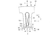
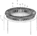
本実施形態の回転電機1は、三相回転電機であり、図1に示すように、固定子40と可動子90とを有している。固定子40は、円筒形状であり内周面に周方向に複数のスロット10aが形成されている固定子鉄心10と、複数のスロット10aに巻かれて装着(挿入)されている波巻構成のコイル30とを有している。可動子90は、固定子40に対して回転可能に支持されている可動子鉄心91と、可動子鉄心91に設けられている少なくとも一対の可動子磁極92、93とを有している。
(Structure of rotating electric machine)
The rotary
本実施形態では、固定子鉄心10には、48個のスロット10aが形成されている。また、本実施形態では、可動子鉄心91は、四組の一対の可動子磁極92、93を備えている。
ここで、固定子40に対する可動子90の回転方向を第一方向(矢印X方向)とする。また、複数の(48個)のスロット10aの深さ方向を第二方向(矢印Y方向)とする。更に、第一方向(矢印X方向)及び第二方向(矢印Y方向)のいずれの方向に対しても直交する方向を第三方向(矢印Z方向)とする。第一方向(矢印X方向)は、回転電機1の周方向に沿った方向に相当し、可動子90の回転方向に相当する。
In the present embodiment, 48
Here, the rotation direction of the
固定子鉄心10は、薄板状の電磁鋼板(例えば、ケイ素鋼板)が第三方向(矢印Z方向)に、複数積層されて形成されている。固定子鉄心10は、バックヨーク部10bと、バックヨーク部10bと一体に形成される複数(本実施形態では、48個)の固定子磁極部10cとを備えている。バックヨーク部10bは、第一方向(矢印X方向)に沿って形成されており、各固定子磁極部10cは、バックヨーク部10bから第二方向(矢印Y方向)(回転電機1の軸心方向)に突出するように形成されている。
The
第一方向(矢印X方向)に隣接する固定子磁極部10c、10cの間には、スロット10aが形成されている。各固定子磁極部10cの先端つまりスロット10aの開口部には、隣接する固定子磁極部10c側つまり第一方向(矢印X方向)に突出する突出部10dが形成されている。
A
可動子90の可動子鉄心91は、薄板状の電磁鋼板(例えば、ケイ素鋼板)が第三方向(矢印Z方向)に、複数積層されており円柱形状に形成されている。可動子鉄心91には、シャフト(不図示)が設けられている。このシャフトは、可動子鉄心91の軸心を第三方向(矢印Z方向)に貫通している。シャフトの第三方向(矢印Z方向)両端部は、軸受部材(不図示)によって、回転可能に支持されている。これにより、可動子鉄心91は、固定子40に対して回転可能に設けられている。
The
可動子鉄心91には、四組の一対の可動子磁極92、93が埋設されている。具体的には、可動子鉄心91には、第一方向(矢印X方向)に、等間隔で、複数の磁石収納部94が形成されている。そして、複数の磁石収納部94には、所定磁極対分(本実施形態では四磁極対分)の永久磁石が埋設されている。可動子90は、永久磁石と、固定子40において発生する回転磁界とによって、固定子40に対して回転する。
Four pairs of pair of mover
永久磁石は、例えば、公知のフェライト系磁石や希土類系磁石を用いることができる。また、永久磁石の製法は、限定されない。永久磁石は、例えば、樹脂ボンド磁石や焼結磁石を用いることができる。樹脂ボンド磁石は、例えば、フェライト系の原料磁石粉末と樹脂などを混合して、射出成形などによって可動子鉄心91に鋳込めて形成される。焼結磁石は、例えば、希土類系の原料磁石粉末を磁界中で加圧成形して、高温で焼き固めて形成される。なお、一対の可動子磁極92、93は、固定子鉄心10の各突出部10dと対向する可動子鉄心91の表面(外周表面)に永久磁石を設ける表面磁石形とすることもできる。また、図1では、一対の可動子磁極92、93のうち、一方の極性(例えば、N極)を備える可動子磁極を可動子磁極92で示し、他方の極性(例えばS極)を備える可動子磁極を可動子磁極93で示している。
As the permanent magnet, for example, a known ferrite magnet or rare earth magnet can be used. Moreover, the manufacturing method of the permanent magnet is not limited. As the permanent magnet, for example, a resin bond magnet or a sintered magnet can be used. The resin-bonded magnet is formed by, for example, mixing a ferrite-based raw material magnet powder and a resin, and casting the resin-bonded magnet into the
コイル30は、銅などの導線30aが巻き回されて形成されている。導線30aの表面は、エナメルなどの絶縁層で被覆されている。コイル30は、U相コイル30U、V相コイル30V、及びW相コイル30Wの3相のコイルを備えている。本実施形態の回転電機1は、三相回転電機であるので、U相コイル30U、V相コイル30V、及びW相コイル30Wは、電気角で120°ずつ位相がずれている。
The
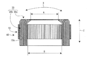
図2に示すように、コイル30は、コイルサイド30bとコイルエンド30cとを有している。コイルサイド30bとコイルエンド30cは、一体に形成されている。コイルサイド30bは、固定子鉄心10のスロット10aに収容されている部位をいう。コイルエンド30cは、コイルサイド30bの第三方向(矢印Z方向)の一端側(図2の紙面上側)のコイルサイド30b、30b同士、及びコイルサイド30bの第三方向(矢印Z方向)の他端側(図2の紙面下側)のコイルサイド30b、30b同士を波巻構成となるように交互に接続している部位をいう。言い換えると、コイルエンド30cは、固定子鉄心10のスロット10aに挿入されたコイル30の折り返し部分であって、固定子鉄心10から軸線方向に突出している部分である。
As shown in FIG. 2, the
(コイルの展開接続図)
図3を用いて、コイルの展開接続図について説明する。図3に示すように、本実施形態では、各相のコイル30U、30V、30Wは、波巻構成である。U相コイル30Uは、第一U相コイル30U1と第二U相コイル30U2とから構成されている。また、V相コイル30Vは、第一V相コイル30V1と第二V相コイル30V2とから構成されている。また、W相コイル30Wは、第一W相コイル30W1と第二W相コイル30W2とから構成されている。
(Expanded connection diagram of coil)
A development connection diagram of the coil will be described with reference to FIG. As shown in FIG. 3, in the present embodiment, the
第一U相コイル30U1の一端と第二U相コイル30U2の一端は、U相端子60Uによって接続されている。第一V相コイル30V1の一端と第二V相コイル30V2の一端は、V相端子60Vによって接続されている。第一W相コイル30W1の一端と第二W相コイル30W2の一端は、W相端子60Wによって接続されている。
第一U相コイル30U1の他端U1N、第二U相コイル30U2の他端U2N、第一V相コイル30V1の他端V1N、第二V相コイル30V2の他端V2N、第一W相コイル30W1の他端W1N、及び第二W相コイル30W2の他端W2Nは、中性点端子70によって接続されている。
One end of the first U-phase coil 30U1 and one end of the second U-phase coil 30U2 are connected by a U-phase terminal 60U. One end of the first V-phase coil 30V1 and one end of the second V-phase coil 30V2 are connected by a V-
The other end U1N of the first U-phase coil 30U1, the other end U2N of the second U-phase coil 30U2, the other end V1N of the first V-phase coil 30V1, the other end V2N of the second V-phase coil 30V2, the first W-phase coil 30W1. The other end W1N of the second W phase coil 30W2 and the other end W2N of the second W phase coil 30W2 are connected by a
第一U相コイル30U1、第二U相コイル30U2、第一V相コイル30V1、第二V相コイル30V2、第一W相コイル30W1、及び第二W相コイル30W2は、図3に示すように、固定子鉄心10の各スロット10aに挿入されている。第一U相コイル30U1と第二U相コイル30U2は、隣接するスロット10aに挿入されている。第一V相コイル30V1と第二V相コイル30V2は、隣接するスロット10aに挿入されている。第一W相コイル30W1と第二W相コイル30W2は、隣接するスロット10aに挿入されている。
The first U-phase coil 30U1, the second U-phase coil 30U2, the first V-phase coil 30V1, the second V-phase coil 30V2, the first W-phase coil 30W1, and the second W-phase coil 30W2 are as shown in FIG. , It is inserted into each
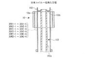
本実施形態では、図7に示すように、第一U相コイル30U1は、コイル挿入機100によって各スロット10aに挿入される際に、複数の第一U相分束コイル30U1−1〜30U1−6に分割されている。同様に、第二U相コイル30U2は、複数の第二U相分束コイル30U2−1〜30U2−6に分割されている。同様に、第一V相コイル30V1は、複数の第一V相分束コイル30V1−1〜30V1−6に分割されている。同様に、第二V相コイル30V2は、複数の第二V相分束コイル30V2−1〜30V2−6に分割されている。同様に、第一W相コイル30W1は、複数の第一W相分束コイル30W1−1〜30W1−6に分割されている。同様に、第二W相コイル30W2は、複数の第二W相コイル30W2−1〜30W2−2に分割されている。
In the present embodiment, as shown in FIG. 7, when the first U-phase coil 30U1 is inserted into each
(回転電機の製造方法の概要)
次に、回転電機1(固定子40)の製造方法の概要について、図4を用いて説明する。以後の説明において、第一U相分束コイル30U1−1〜30U1−6及び第二U相分束コイル30U2−1〜30U2−6を、分束コイル30U**と略す。同様に、第一V相コイル30V及び第二V相分束コイル30V2−1〜30V2−6を、分束コイル30V**と略す。同様に、第一W相コイル30W及び第二W相分束コイル30W2−1〜30W2−6を、分束コイル30W**と略す。
(Outline of manufacturing method of rotary electric machine)
Next, the outline of the manufacturing method of the rotary electric machine 1 (stator 40) will be described with reference to FIG. In the following description, the first U-phase unbalanced coil 30U1-1 to 30U1-6 and the second U-phase unbalanced coil 30U2-1 to 30U2-6 are abbreviated as the
まず、スロット紙挿入工程において、固定子鉄心10の各スロット10a内に、断面形状がU字形状に折り曲げられたスロット紙20を挿入する。スロット紙20は、スロット10a内で各相のコイル30U、30V、30Wの周囲を取り囲み、各相のコイル30U、30V、30Wと固定子鉄心10との間を絶縁するものである。
First, in the slot paper inserting step, the
次に、分束コイル形成工程において、導線30aから、UVW各相の分束コイル30U**、30v**、30w**をそれぞれ形成する。この分束コイル形成工程については、後で詳細に説明する。
次に、分束コイル一括挿入工程において、まず、分束コイル形成工程において形成されたUVW各相の複数の分束コイル30U**、30v**、30w**をコイル挿入機100にセットする。次に、コイル挿入機100によって、UVW各相の分束コイル30U**、30v**、30w**を、同時に一括して固定子鉄心10のスロット10aに挿入する。このように、本実施形態では、従来の固定子の製造方法と異なり、UVW各相の分束コイル30U**、30v**、30w**が同時に一括して固定子鉄心10のスロット10aに挿入される。分束コイル一括挿入工程については、後で詳細に説明する。
Next, in the bundle coil forming step, the bundle coils 30U **, 30v **, and 30w ** of each UVW phase are formed from the
Next, in the grouping coil batch insertion step, first, a plurality of grouped
次に、UVW相コイル端子装着工程において、UVW各相の複数の分束コイル30U**、30v**、30w**の一端に、それぞれ、U相端子60U、V相端子60V、W相端子60Wを装着する。UVW相コイル端子装着工程において、UVW各相の複数の分束コイル30U**、30v**、30w**の一端が連結され、それぞれ、U相コイル30U、V相コイル30V、W相コイル30Wが形成される。
Next, in the process of mounting the UVW phase coil terminal, the
次に、中間検査工程において、U相コイル30U、V相コイル30V、及びW相コイル30Wのそれぞれに電流を流して、U相コイル30U、V相コイル30V、及びW相コイル30Wと固定子鉄心10との間が絶縁されていることを検査する。
次に、中性点装着工程において、U相コイル30U、V相コイル30V、及びW相コイル30Wの他端に、中性点端子70を装着する。この中性点装着工程において、U相コイル30U、V相コイル30V、及びW相コイル30Wの他端が相互に結線される。
Next, in the intermediate inspection step, a current is passed through each of the
Next, in the neutral point mounting step, the
次に、ワニス塗布工程において、コイル30のコイルエンド30cにワニスを塗布する。
次に、検査工程において、製造した固定子40の特性を検査することによって、製造した固定子40の良否を判定し、固定子40の製造が完了する。
Next, in the varnish coating step, the varnish is applied to the
Next, in the inspection step, by inspecting the characteristics of the manufactured
(分束コイル形成工程)
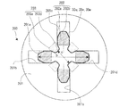
次に、図5A、図5B、図6A、及び図6Bを用いて、分束コイル形成工程について説明する。分束コイル形成工程に用いられるコイル形成機200は、図5A及び図5Bに示すように、基部材201、4つの柱部材202、及び4つの押圧部材203から構成されている。基部材201は、板状である。基部材201には、十字形状の摺動穴201aが貫通形成されている。摺動穴201aは、4つの摺動レーン201b〜201eから構成されている。4つの摺動レーン201b〜201eは、摺動穴201aの中心201a1(図6A示)で接続し、摺動穴201aの中心201a1から外側に延在している。隣接する摺動レーン201b〜201eは、直交している。
(Bundling coil forming process)
Next, the bundle coil forming step will be described with reference to FIGS. 5A, 5B, 6A, and 6B. As shown in FIGS. 5A and 5B, the
コイル形成機200の説明において、摺動穴201aの中心201a1から遠い側を外側とし、摺動穴201aの中心201a1から近い側を内側とする。
柱部材202は、柱形状である。図6Aに示すように、柱部材202は、基部202aと先端部202bとから構成されている。基部202aの断面形状は長方形状である。先端部202bは、基部202aの外側(摺動穴201aの中心201a1から遠い側)に接続している。先端部202bの断面形状は等脚台形である。先端部202bの先端側(外側)の辺は、先端部202bの基端側(内側)の辺よりも短く設定されている。4つの柱部材202は、それぞれ、各摺動レーン201b〜201eに挿通されて、各摺動レーン201b〜201e内を摺動可能に設けられている。4つの柱部材202は、各摺動レーン201b〜201eの外側の第一位置(図5A、図6A示)と、各摺動レーン201b〜201eの中心側の第二位置(図5B、図6B示)間を同時に摺動する。
In the description of the
The
押圧部材203は、ブロック形状である。図6Aに示すように、押圧部材203は、基部203aと先端部203bとから構成されている。基部203aの断面形状は長方形状である。先端部203bは、基部203aの内側(摺動穴201aの中心201a1から近い側)に接続している。先端部203bの断面形状は等脚台形である。先端部203bの先端側(内側)の辺は、先端部203bの基端側(外側)の辺よりも短く設定されている。4つの押圧部材203は、4つの柱部材202が第一位置に位置している場合に、隣接する柱部材202の最も外側の位置間を結んだ線の中間部分の外側にそれぞれ配置されている。4つの押圧部材203は、摺動穴201aの中心201a1に対して、近づき、又は遠ざかるように移動する。4つの柱部材202と連動して移動する。つまり、4つの柱部材202が第一位置に位置している場合には、4つの押圧部材203は押圧部材203の移動範囲のうち最も摺動穴201aの中心部分から遠い位置である第三位置に位置している(図5A、図6A示)。一方で、4つの柱部材202が第二位置に位置している場合には、4つの押圧部材203は押圧部材203の移動範囲のうち最も摺動穴201aの中心部分に近い位置である第四位置に位置している(図5B、図6B示)。
The pressing
第二U相分束コイル30U2−1〜30U2−6、第二V相分束コイル30V2−1〜30V2−6、及び第二W相分束コイル30W2−1〜30W2−6を形成するコイル形成機200は、第一U相分束コイル30U1−1〜30U1−6、第一V相分束コイル30V1−1〜30V1−6、及び第一W相分束コイル30W1−1〜30W1−6を形成するコイル形成機200よりも、柱部材202及び押圧部材203の外形が小さく設定されている。
Coil formation to form the second U-phase unbalanced coil 30U2-1 to 30U2-6, the second V-phase unbalanced coil 30V2-1 to 30V2-6, and the second W-phase unbalanced coil 30W2-1 to 30W2-6. The
図5A及び図6Aに示すように、4つの柱部材202が第一位置であり、4つの押圧部材203が第三位置である状態で、導線30aが、巻線機(不図示)によって、隣接する柱部材202の外側部分を結ぶように4つの柱部材202に巻き付けられる。なお、コイル形成機200自体が回転して、導線30aが4つの柱部材202に巻き付けられるようにしても差し支え無い。
As shown in FIGS. 5A and 6A, with the four
第一U相分束コイル30U1−1〜30U1−6、第一V相分束コイル30V1−1〜30V1−6、及び第一W相分束コイル30W1−1〜30W1−6を、コイル形成機200によって、それぞれ形成する際には、末尾の符号が大きくなるに従って、導線30aの本数が多くなるように、4つの柱部材202に導線30aが巻き付けられる。
また、第二U相分束コイル30U2−1〜30U2−6、第二V相分束コイル30V2−1〜30V2−6及び第二W相分束コイル30W2−1〜30W2−6を、コイル形成機200によって、それぞれ形成する際には、末尾の符号が大きくなるに従って、導線30aの本数が多くなるように、4つの柱部材202に導線30aが巻き付けられる。
The first U-phase unbalanced coil 30U1-1 to 30U1-6, the first V-phase unbalanced coil 30V1-1 to 30V1-6, and the first W-phase unbalanced coil 30W1-1 to 30W1-6 are coiled by a coil forming machine. When each of the 200 is formed, the
Further, the second U-phase unbalanced coil 30U2-1 to 30U2-6, the second V-phase unbalanced coil 30V2-1 to 30V2-6, and the second W-phase unbalanced coil 30W2-1 to 30W2-6 are coiled. When each is formed by the
第一U相分束コイル30U1−1〜30U1−6、第一V相分束コイル30V1−1〜30V1−6及び第一W相分束コイル30W1−1〜30W1−6を、コイル形成機200によって、それぞれ形成する際には、末尾の符号が大きくなるに従って、第一位置にある対向する柱部材202の外側間の距離a(図6A示)を小さくする。
また、第二U相分束コイル30U2−1〜30U2−6、第二V相分束コイル30V2−1〜30V2−6及び第二W相分束コイル30W2−1〜30W2−6を、コイル形成機200によって、それぞれ形成する際には、末尾の符号が大きくなるに従って、第一位置にある対向する柱部材202の外側間の距離a(図6A示)を小さくする。
The first U-phase unbalanced coil 30U1-1 to 30U1-6, the first V-phase unbalanced coil 30V1-1 to 30V1-6, and the first W-phase unbalanced coil 30W1-1 to 30W1-6 are combined with the
Further, the second U-phase unbalanced coil 30U2-1 to 30U2-6, the second V-phase unbalanced coil 30V2-1 to 30V2-6, and the second W-phase unbalanced coil 30W2-1 to 30W2-6 are coiled. When each is formed by the
次に、4つの柱部材202を第二位置に移動させるとともに、4つの押圧部材203を第四位置に移動させて(図5B、図6B示)、図7に示す各相の分束コイル30U1−1〜30U1−6、30U2−1〜30U2−6、30V1−1〜30V1−6、30V2−1〜30V2−6、30W1−1〜30W1−6、及び30W2−1〜30W2−6をそれぞれ形成する。
Next, the four
第一U相分束コイル30U1−1〜30U1−6、第一V相分束コイル30V1−1〜30V1−6及び第一W相分束コイル30W1−1〜30W1−6をそれぞれ形成する際には、末尾の符号が大きくなるに従って、第二位置にある対向する柱部材202の外側間の距離b(図6B示)を小さくするとともに、第三位置にある対向する押圧部材203の内側間の距離c(図6B示)を小さくする。
When forming the first U-phase unbalanced coil 30U1-1 to 30U1-6, the first V-phase unbalanced coil 30V1-1 to 30V1-6, and the first W-phase unbalanced coil 30W1-1 to 30W1-6, respectively. As the code at the end increases, the distance b between the outsides of the opposing
第二U相分束コイル30U2−1〜30U2−6、第二V相分束コイル30V2−1〜30V2−6、及び第二W相分束コイル30W2−1〜30W2−6を、コイル形成機200によって、それぞれ形成する際には、末尾の符号が大きくなるに従って、第二位置にある対向する柱部材202の外側間の距離b(図6B示)を小さくするとともに、第三位置にある対向する押圧部材203の内側間の距離c(図6B示)を小さくする。
The second U-phase unbalanced coil 30U2-1 to 30U2-6, the second V-phase unbalanced coil 30V2-1 to 30V2-6, and the second W-phase unbalanced coil 30W2-1 to 30W2-6 are coil forming machines. When each of the 200s is formed, the distance b (shown in FIG. 6B) between the outer sides of the opposing
このように形成された各相の分束コイル30U1−1〜30U1−6、30U2−1〜30U2−6、30V1−1〜30V1−6、30V2−1〜30V2−6、30W1−1〜30W1−6、及び30W2−1〜30W2−6は、末尾の符号が大きくなるに従って、導線30aの本数が多く設定されている。言い換えると、各相の分束コイル30U1−1〜30U1−6、30U2−1〜30U2−6、30V1−1〜30V1−6、30V2−1〜30V2−6、30W1−1〜30W1−6、及び30W2−1〜30W2−6は、末尾の符号が小さくなるに従って、導線30aの本数が少なく設定されている。
The fractionated coils of each phase formed in this way 30U1-1 to 30U1-6, 30U2-1 to 30U2-6, 30V1-1 to 30V1-6, 30V2-1 to 30V2-6, 30W1-1 to 30W1- In No. 6 and 30W2-1 to 30W2-6, the number of
また、このように形成された各相の分束コイル30U1−1〜30U1−6、30U2−1〜30U2−6、30V1−1〜30V1−6、30V2−1〜30V2−6、30W1−1〜30W1−6、及び30W2−1〜30W2−6は、末尾の符号が大きくなるに従って、1巻分の導線30aの長さが短く設定されている。
Further, the shunting coils of each phase formed in this way, 30U1-1 to 30U1-6, 30U2-1 to 30U2-6, 30V1-1 to 30V1-6, 30V2-1 to 30V2-6, 30W1-1 to 1 In 30W1-6 and 30W2-1 to 30W2-6, the length of the
(分束コイル一括挿入工程)
図7において、紙面上方をコイル挿入機100の上方とし、紙面下方をコイル挿入機100の下方とする。
分束コイル一括挿入工程は、図8A〜図8Dに示すように、コイルセット工程、固定子鉄心セット工程、及び分束コイル一括挿入工程を有している。
(Batch coil insertion process)
In FIG. 7, the upper part of the paper surface is the upper part of the
As shown in FIGS. 8A to 8D, the bundled coil batch insertion step includes a coil setting step, a stator core setting step, and a bundled coil batch insertion step.
図7及び図8Aに示すように、分束コイル一括挿入工程において用いられるコイル挿入機100は、基部101、複数のブレード102、プッシャー103とから構成されている。基部101は、板形状又はブロック形状であり、中心に貫通穴101a(図8A示)が形成されている。ブレード102は、棒状である。複数のブレード102は、基部101の貫通穴101aの内周面に、一定角度をおいて設けられ、基部101から上方に突出している。つまり、複数のブレード102は、互いに離間して円周上に配置されている。ブレード102の数は、スロット10aの数と同一であり、本実施形態では、48本である。そして、隣接するブレード102の間には、1本の導線30aのみが挿入可能な隙間102a(図7、図9示)が形成されている。
As shown in FIGS. 7 and 8A, the
図8Aに示すように、プッシャー103は、複数のブレード102の内側に設けられ、ブレード102の内側部分と対向している。プッシャー103は、図示しない移動機構によって、ブレード102の形成方向(上下方向)に沿って移動する。プッシャー103は、本体部103aと複数の押込部103bとから構成されている。本体部103aは、円筒形状又は円柱形状である。複数の押込部103bは、長方形状の板形状であり、本体部103aの外周面に、周方向に一定角度をおいて、本体部103aの半径方向に沿って設けられている(図9示)。押込部103bの数は、スロット10aの数と同一であり、本実施形態では、48個である。図9に示すように、固定子鉄心10がコイル挿入機100にセットされた状態では、各押込部103bは、各ブレード102の内側に対向している。
As shown in FIG. 8A, the
図3のコイルの展開接続図に示す各スロット10aは、図7に示す各ブレード102の間に形成された隙間102aに対応している。コイルセット工程では、移送装置(不図示)によって、図3に示すコイルの展開接続図に従って、各相の分束コイル30U1−1〜30U1−6、30U2−1〜30U2−6、30V1−1〜30V1−6、30V2−1〜30V2−6、30W1−1〜30W1−6、30W2−1〜30W2−6を、ブレード102間にブレード102の形成方向に重ねて層状にそれぞれ挿入する(図7、図8A示)。
Each
各第一U相分束コイル30U1−1〜30U1−6及び各第二U相分束コイル30U2−1〜30U2−6は、これらの末尾の符号の順番に上方から下方に、ブレード102間にブレード102の形成方向に重ねられて層状に挿入された状態で装着されている。各第一V相分束コイル30V1−1〜30V1−6及び各第二V相分束コイル30V2−1〜30V2−6は、これらの末尾の符号の順番に上方から下方に、ブレード102間にブレード102の形成方向に重ねられて層状に挿入された状態で装着されている。各第一W相分束コイル30W1−1〜30W1−6及び各第二W相分束コイル30W2−1〜30W2−6は、これらの末尾の符号の順番に上方から下方に、ブレード102間にブレード102の形成方向に重ねられて層状に挿入された状態で装着されている。
The first U-phase fractionated coils 30U1-1 to 30U1-6 and the second U-phase fractionated coils 30U2-1 to 30U2-6 are placed between the
図7や図3に示すように、第二U相分束コイル30U2−1〜30U2−6は、第一U相分束コイル30U1−1〜30U1−6が挿入されている隙間102aよりも、1つ内側の隙間102aに配置されている。同様に、第二V相分束コイル30V2−1〜30V2−6は、第一V相分束コイル30V1−1〜30V1−6が挿入されている隙間102aよりも、1つ内側の隙間102aに配置されている。同様に、第二W相分束コイル30W2−1〜30W2−6は、第一W相分束コイル30W1−1〜30W1−6が挿入されている隙間102aよりも、1つ内側の隙間102aに配置されている。
As shown in FIGS. 7 and 3, the second U-phase balancing coil 30U2-1 to 30U2-6 is larger than the
次に、固定子鉄心セット工程において、図9に示すように、スロット10aの開口部の位置が各ブレード102間に形成された隙間102aの位置と一致するように、固定子鉄心10をコイル挿入機100にセットする(図8B示)。
固定子鉄心セット工程において、各ブレード102間にそれぞれ挿入されている各分束コイル30U1−1〜30U1−6、30U2−1〜30U2−6、30V1−1〜30V1−6、30V2−1〜30V2−6、30W1−1〜30W1−6、30W2−1〜30W2−6(以下、適宜、分束コイル30**と表す)を構成する導線30aの本数は、固定子鉄心10に近い各分束コイル30**程、少なく設定されている。
また、固定子鉄心セット工程において、各ブレード102間にそれぞれ挿入されている各分束コイル30**を構成する導線30aの長さは、固定子鉄心10から遠い各分束コイル30**程、短く設定されている。
Next, in the stator core setting step, as shown in FIG. 9, the
In the stator core setting process, each bundle coil 30U1-1 to 30U1-6, 30U2-1 to 30U2-6, 30V1-1 to 30V1-6, 30V2-1 to 30V2 inserted between the
Further, in the stator core setting process, the length of the
次に、分束コイル一括挿入工程において、プッシャー103を固定子鉄心10側に移動させる。すると、プッシャー103の各押込部103bによって、各相の分束コイル30**のうち、ブレード102よりも内周側に突出している部分が、固定子鉄心10側に押し上げられる。すると、固定子鉄心10側(上方側)にある分束コイル30**から順次スロット10aに順次重ねられて層状に挿入される(図8Cの状態)。つまり、プッシャー側103側(下方側)にあるブレード102間にそれぞれ挿入された分束コイル30**で、これらの分束コイル30**よりも固定子鉄心10側(上方側)に隣接する各相の分束コイルが押圧される。すると、ブレード102間にそれぞれ挿入された複数の分束コイル30**が、各スロット10aに順次重ねられて層状に挿入される(図8Dの状態)。
Next, in the bundling coil batch insertion step, the
本実施形態では、各相のコイル30U、30V、30Wは、それぞれ、複数の分束コイル30**に分割されて構成されている。これにより、各相のコイル30U、30V、30Wが分割されていない構成と比較して、分束コイル30**の剛性は低いため、分束コイル30**はより変形し易い。このため、プッシャー103側にある各ブレード102間にそれぞれ挿入された複数の分束コイル30**で、この分束コイル30**よりも固定子鉄心10側に隣接する分束コイル30**を押圧させて、各相のそれぞれの複数の分束コイル30**を一度に各スロット10aに順次重ねて挿入することができる。
In the present embodiment, the
また、各ブレード102間にそれぞれ挿入された状態で装着されている各分束コイル30**を構成する導線30aの本数は、固定子鉄心10に近い各分束コイル30**程、少なく設定されている。言い換えると、各スロット10aにそれぞれ重ねられて層状に挿入された状態で装着されている各分束コイル30**を構成する導線の本数は、内周側の分束コイル30**よりも外周側の分束コイル30**のほうが、少なく設定されている。これにより、固定子鉄心10に近い各分束コイル30**、つまり、先にスロット10aに挿入される分束コイル30**の方が、その後に挿入される分束コイル30**よりも、分束コイル30**の剛性が小さい。分束コイル30**の剛性が小さい程、分束コイル30**が柔軟であるので、分束コイル30**はスロット10aに挿入されやすい。このため、先にスロット10aに挿入される分束コイル30**が確実にスロット10aに挿入される。また、分束コイル30**の剛性が大きい程、分束コイル30**が変形し難い。このため、固定子鉄心10に近い分束コイル30**よりも、プッシャー103に近い分束コイル30**、つまり、後にスロット10aに挿入される分束コイル30**が変形し難い。よって、変形し難い、後にスロット10aに挿入される各相の分束コイル30**で、その前に挿入され始めた分束コイル30**を確実に押圧させてスロット10aに挿入させることができる。この結果、全ての分束コイル30**が各スロット10aに確実に挿入される。
Further, the number of
なお、この分束コイル一括挿入工程において、図示しない、ウエッジプッシャーによって、上記各相の分束コイルが各スロット10aに挿入された直後に、ウエッジ紙80(図10示)が各スロット10aの開口部を閉塞するように、各スロット10aに挿入される。
In this batch insertion step of the bundled coils, the wedge paper 80 (shown in FIG. 10) opens the
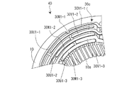
このように製造された固定子40について以下に説明する。図11は、固定子40のスロット10aに挿入された各分束コイル30**の折り返し部分であって、固定子鉄心10の端部から軸線方向に突出しているコイルエンド30cを模式的に表した斜視図である。なお、図11において、便宜的に各相のコイル30U1〜30W1は、3つの分束コイル30**に分割されているものとする。
The
図11に示すように、1つの分束コイル30U1−1〜30U1−3、30V1−1〜30V1−3、30W1−1〜30W1−3が挿入されている2つのスロット10a間の距離は、固定子鉄心10の内側に位置するに従って短い。このため、もし、各上記分束コイルを構成する導線30aの長さが同一であるとすると、固定子鉄心10の内側に位置する上記分束コイル程、この分束コイル30**のコイルエンド30cの固定子鉄心10からの突出長さが大きくなる。そこで、本実施形態では、上記したように、固定子鉄心セット工程において、各ブレード102間にそれぞれ挿入された状態で装着されている各分束コイル30**を構成する導線30aの長さを、固定子鉄心10から遠い各分束コイル30**程、短く設定している。つまり、各スロット10aにそれぞれ重ねられて挿入された状態で装着されている各前記分束コイル**を構成する導線30aの1巻分の長さは、外周側の分束コイル30**よりも内周側の分束コイル30**のほうが、短く設定されている。このため、図10に示すように、分束コイル一括挿入工程によって、各相の分束コイル30**が各スロット10aに挿入された状態でコイルエンド30cは、外周側から内周側まで、固定子鉄心10の端部からの突出量が殆ど一定である。よって、固定子鉄心10の内側に位置しているコイルエンド30c、つまり、固定子鉄心10の端部から大きく突出しているコイルエンド30cを押圧して、固定子鉄心10の端部から一定の距離内に収めるコイルエンド成型工程が不要となる。
As shown in FIG. 11, the distance between the two
本実施形態では、上述したように、固定子鉄心セット工程において、各ブレード102間にそれぞれ挿入されている各分束コイル30**を構成する導線30aの長さは、固定子鉄心10から遠い各分束コイル30**程、つまり、各スロット10aにおいて固定子鉄心10の内側に挿入される分束コイル30**程、短く設定されている。これにより、分束コイル一括挿入工程によって、各相の分束コイル30**が各スロット10aに挿入された状態で、図2に示すように、コイルエンド30cの一方側の固定子鉄心10の端面から突出する方向に最も離れた位置における内径Aは、固定子鉄心10の内径Bよりも小さく設定されている。このため、分束コイル一括挿入工程時に、内側の分束コイル30**のコイルエンド30cによって、この分束コイル30**の外側に有る分束コイル30**のコイルエンド30cが外側に押されない。これにより、内側の分束コイル30**のコイルエンド30cが、この分束コイル30**よりも外側にあるコイルエンド30cを押圧することによる、導線30aの表面に形成されは被膜が破壊されることが防止される。
In the present embodiment, as described above, in the stator core setting step, the length of the
本実施形態では、図2に示す状態でも、回転電機の固定子40として成立するので、固定子鉄心10の内径Bよりもより内側にあるコイルエンド30cを、固定子鉄心10の内径Bよりも外側に成型する必要が無い。このため、固定子鉄心10の内径Bよりもより内側にあるコイルエンド30cを、固定子鉄心10の内径Bよりも外側に成型することによって、導線30aに表面に形成された被膜が破壊されることが防止される。
In the present embodiment, even in the state shown in FIG. 2, it is established as the
(従来と本実施形態の回転電機の製造方法の比較)
従来の回転電機の製造方法では、各相のコイル30U、30V、30Wを固定子鉄心10のスロット10aに挿入するために、図12に示すように、スロット紙挿入工程の後に、U相巻線工程、U相挿入工程、U相中間工程、V相巻線工程、V相挿入工程、V相中間工程、W相巻線工程、W相挿入工程、及び最終成形工程が実行される。U相中間工程及びV相中間工程は、次にスロット10aに挿入されるコイル30V、30Wのスロット10aへの挿入の妨げとならないように、スロット10aに挿入されているコイル30U、30Vのコイルエンド30cを、固定子鉄心10の外周側に変形させる工程である。また、最終成形工程では、U相中間工程及びV相中間工程によって、固定子鉄心10の外周側に変形されたコイルエンド30cを、固定子鉄心10の内周側に変形させて、U相中間工程及びV相中間工程が実行される前の状態に戻す工程である。
(Comparison between the conventional and the manufacturing methods of the rotary electric machine of the present embodiment)
In the conventional manufacturing method of a rotary electric machine, in order to insert the
一方で、本実施形態の回転電機1の製造方法では、図4に示すように、分束コイル一括挿入工程において、UVW各相の複数の分束コイル30U**、30v**、30w**が、一括して固定子鉄心10の各スロット10aに挿入される。このため、本実施形態の回転電機1の製造方法では、図12に示す従来の回転電機1の製造方法と比較して、U相、V相、及びW相の各相のコイル30U、30V、30Wを順次固定子鉄心10のスロット10aに挿入する必要が無く、U相中間工程及びV相中間工程も不要である。また、本実施形態の固定子の製造方法では、U相中間工程及びV相中間工程が不要であるため、U相中間工程及びV相中間工程によって固定子鉄心10の外周側に変形されたコイルエンド30cを、U相中間工程及びV相中間工程が実行される前の状態に戻す最終成形工程が不要となる。このように、本実施形態の固定子の製造方法では、従来の固定子の製造方法と比較して、コイル30を固定子鉄心10のスロット10aに挿入するための工程を大幅に削減することができる。
On the other hand, in the manufacturing method of the rotary
(本実施形態の効果)
以上の説明から明らかなように、コイル30U、30V、30Wは複数の分束コイル30**に分割され、分束コイル一括挿入工程において、プッシャー103を固定子鉄心10側に移動させることにより、プッシャー103側にある各ブレード102間にそれぞれ挿入された複数の分束コイル30**で、この分束コイル30**よりも固定子鉄心10側に隣接する分束コイル30**を押圧させて、各相のそれぞれの複数の分束コイル30**を一度に各スロット10aに順次重ねて層状に挿入する。このように、コイル30U、30V、30Wは複数の分束コイル30**に分割されているので、分割されていないコイル30U、30V、30Wと比較して、分束コイル30**の剛性は低いため、分束コイル30**は変形し易い。このため、分束コイル一括挿入工程において、全ての相の分束コイル30**を、一度に固定子鉄心10の各スロット10aに重ねられて層状に挿入することができる。この結果、各相のコイル30を挿入するのに必要な工程を大幅に削減することができる。また、従来のように、1つの相のコイル30U、30V、30Wを固定子鉄心10のスロット10aに挿入した後に、次に挿入されるコイル30U、30V、30Wのスロット10aへの挿入の妨げとならないように、スロット10aに挿入されたコイル30U、30V、30Wの一方側のコイルエンド30cを固定子鉄心10の外周側に変形させる中間成型が不要となる。このように、各相のコイル30U、30V、30Wを挿入するのに必要な工程を大幅に削減することができ、より短時間で製造することができる回転電機1の製造方法を提供することができる。
(Effect of this embodiment)
As is clear from the above description, the
また、固定子鉄心セット工程において、各ブレード102間にそれぞれ重ねられて層状に挿入されている各分束コイル30**を構成する導線の本数は、固定子鉄心10に近い分束コイル30**程、少なく設定されている。これにより、分束コイル一括挿入工程において、固定子鉄心10に近い各分束コイル30**、つまり、先にスロット10aに挿入される分束コイル30**の方が、その後に挿入される分束コイル30**よりも、分束コイル30**の剛性が小さい。分束コイル30**の剛性が小さい程、分束コイル30**が柔軟であるので、分束コイル30**はスロット10aに挿入されやすい。このため、先にスロット10aに挿入される分束コイル30**が確実にスロット10aに挿入される。また、分束コイル30**の剛性が大きい程、分束コイル30**が変形し難い。このため、固定子鉄心10に近い分束コイル30**よりも、プッシャー103に近い分束コイル30**、つまり、後にスロット10aに挿入される分束コイル30**が変形し難い。よって、変形し難い、後にスロット10aに挿入される各相の分束コイル30**で、その前に挿入され始めた分束コイル30**を確実に押圧させてスロット10aに挿入させることができる。この結果、全ての分束コイル30**が各スロット10aに確実に挿入される。
Further, in the stator core setting process, the number of wires constituting each
また、固定子鉄心セット工程において、各ブレード102間にそれぞれ重ねられて層状に挿入されている各分束コイル30**を構成する導線30aの長さは、固定子鉄心10から遠い各分束コイル30**程、短く設定されている。これにより、固定子鉄心10から遠い各分束コイル30**程、つまり、外周側の分束コイル30**よりも内周側の分束コイル30**程、導線30aが短くなる。このため、内周側の分束コイル30**の一方側のコイルエンド30cの固定子鉄心10の端面からの突出長さを抑制することができる。この結果、固定子40に用いられる導線30aの長さをより短くすることができ、各相のコイル30U、30V、30Wの電気抵抗を低減することができ、固定子40の質量を削減することができる。また、固定子鉄心10の端面から大きく突出した内周側の分束コイル30**の一方側のコイルエンド30cを押圧して、固定子鉄心10の端面から突出した一方側のコイルエンド30cの突出量を制限する成型工程が不要となる。
Further, in the stator core setting step, the length of the
また、図2に示すように、スロット10aに挿入された状態で装着された各分束コイル30**の一方側のコイルエンド30cの固定子鉄心10の端面から突出する方向に最も離れた位置における内径Aは、固定子鉄心10の内径Bよりも小さく設定されている。図2に示す状態でも、回転電機の固定子40として成立する。このため、固定子鉄心10の内径Bよりもより内側にあるコイルエンド30cを、固定子鉄心10の内径Bよりも外側に成型することによって、導線30aに表面に形成された被膜が破壊されることが防止される。
Further, as shown in FIG. 2, the position farthest from the end surface of the
また、各相のコイル30は、複数の分束コイル30**に分割されて構成されている。そして、各スロット10aにそれぞれ重ねられて層状に挿入された状態で装着された各分束コイル30**を構成する導線30aの本数は、内周側の分束コイル30**よりも外周側の分束コイル30**のほうが、少なく設定されている。各分束コイル30**を構成する導線30aの本数が少ない程、分束コイル30**の剛性が小さくなるので、内周側の分束コイル30**よりも外周側の分束コイル30**のほうが、剛性が小さい。このため、外周側の分束コイル30**、つまり、先にスロット10aに挿入される分束コイル30**の方が、その後に挿入される分束コイル30**よりも、剛性が小さい。分束コイル30**の剛性が小さい程、分束コイル30**が柔軟であるので、分束コイル30**はスロットに挿入されやすい。このため、先にスロット10aに挿入される分束コイル30**が確実にスロット10aに挿入される。
Further, the
また、外周側の分束コイル30**よりも内周側の分束コイル30**の方が、導線30aの本数が多い。このため、外周側の分束コイル30**よりも内周側の分束コイル30**の方が、剛性が大きく、変形し難い。よって、外周側の分束コイル30**よりも内周側の分束コイル30**、つまり、先にスロット10aに挿入される分束コイル30**よりも後にスロット10aに挿入される分束コイル30**の方が変形し難い。この結果、変形し難い後にスロット10aに挿入される内周側の分束コイル30**で、その前に挿入され始めた外周側の分束コイル30**を確実に押圧させてスロット10aに挿入させることができる。
Further, the number of
このように、後にスロット10aに挿入される内周側の分束コイル30**で、その前に挿入され始めた外周側の分束コイル30**を押圧させてスロット10aに挿入させることができるので、全ての分束コイル30**を一度に各スロット10aに重ねて層状に挿入することができる。この結果、固定子鉄心10のスロット10aに各相のコイル30を挿入するのに必要な工程を削減し、より短時間で製造することができる回転電機1を提供することができる。
In this way, the inner peripheral
図11に示すように、1つの分束コイル30**が挿入されている2つのスロット10a間の距離は、固定子鉄心10の内側に位置するに従って短い。このため、もし、各分束コイル30**を構成する導線30aの長さが同一であるとすると、外周側の分束コイル30**よりも内周側の分束コイル30**程、この分束コイル30**の一方側のコイルエンド30cの固定子鉄心10の端面からの突出長さが大きくなる。そこで、各スロット10aにそれぞれ重ねられて層状に挿入された状態で装着されている各分束コイル30**を構成する導線30aの1巻分の長さは、外周側の分束コイル30**よりも内周側の分束コイル30**のほうが、短く設定されている。このため、内周側の分束コイル30**の一方側のコイルエンド30cの固定子鉄心10の端面からの突出長さを抑制することができる。この結果、固定子40に用いられる導線30aの長さをより短くすることができ、各相のコイル30U、30V、30Wの電気抵抗を低減することができ、固定子40の質量を削減することができる。また、固定子鉄心10の内側に位置し固定子鉄心10から大きく突出したコイルエンド30cを押圧して、固定子鉄心10から突出したコイルエンド30cの突出量を制限する成型工程が不要となる。
As shown in FIG. 11, the distance between the two
(コイルが同心巻の実施形態)
図13に示すように、各相のコイル30U、30V、30Wが同心巻構成である実施形態にも、本発明の回転電機1及び回転電機1の製造方法は適用可能である。この実施形態でも、U相コイル30Uは、第一U相コイル30U1と第二U相コイル30U2とから構成されている。また、V相コイル30Vは、第一V相コイル30V1と第二V相コイル30V2とから構成されている。また、W相コイル30Wは、第一W相コイル30W1と第二W相コイル30W2とから構成されている。
(Coil is concentric winding embodiment)
As shown in FIG. 13, the manufacturing method of the rotary
この実施形態でも、第一U相コイル30U1は、コイル挿入機100によって各スロット10aに挿入される際に、複数の第一U相分束コイル30U1−1〜30U1−6に分割されている。同様に、第二U相コイル30U2は、複数の第二U相分束コイル30U2−1〜30U2−6に分割されている。同様に、第一V相コイル30V1は、複数の第一V相分束コイル30V1−1〜30V1−6に分割されている。同様に、第二V相コイル30V2は、複数の第二V相分束コイル30V2−1〜30V2−6に分割されている。同様に、第一W相コイル30W1は、複数の第一W相分束コイル30W1−1〜30W1−6に分割されている。同様に、第二W相コイル30W2は、複数の第二W相コイル30W2−1〜30W2−2に分割されている。
Also in this embodiment, the first U-phase coil 30U1 is divided into a plurality of first U-phase unbalanced coils 30U1-1 to 30U1-6 when inserted into each
コイルセット工程では、移送装置(不図示)によって、図13に示すコイルの展開接続図に従って、各相の分束コイル30U1−1〜30U1−6、30U2−1〜30U2−6、30V1−1〜30V1−6、30V2−1〜30V2−6、30W1−1〜30W1−6、30W2−1〜30W2−6を、ブレード102間にブレード102の形成方向に重ねてそれぞれ層状に挿入する。
In the coil setting step, the unfolded coils 30U1-1 to 30U1-6, 30U2-1 to 30U2-6, and 30V1-1 to each phase are used by a transfer device (not shown) according to the development connection diagram of the coils shown in FIG. 30V1-6, 30V2-1 to 30V2-6, 30W1-1 to 30W1-6, and 30W2-1 to 30W2-6 are inserted in layers between the
固定子鉄心セット工程において、各ブレード102間にそれぞれ挿入された状態で装着されている各分束コイル30U1−1〜30U1−6、30U2−1〜30U2−6、30V1−1〜30V1−6、30V2−1〜30V2−6、30W1−1〜30W1−6、30W2−1〜30W2−6を構成する導線30aの本数は、固定子鉄心10に近い各分束コイル30**程、少なく設定されている。
また、固定子鉄心セット工程において、各ブレード102間にそれぞれ挿入された状態で装着されている各分束コイル30U1−1〜30U1−6、30U2−1〜30U2−6、30V1−1〜30V1−6、30V2−1〜30V2−6、30W1−1〜30W1−6、30W2−1〜30W2−6を構成する導線30aの長さは、固定子鉄心10から遠い各分束コイル30**程、短く設定されている。
In the stator core setting process, each bundle coil 30U1-1 to 30U1-6, 30U2-1 to 30U2-6, 30V1-1 to 30V1-6, which are mounted while being inserted between the
Further, in the stator core setting process, each bundle coil 30U1-1 to 30U1-6, 30U2-1 to 30U2-6, 30V1-1 to 30V1-are mounted in a state of being inserted between the
分束コイル一括挿入工程において、プッシャー103を固定子鉄心10側に移動させと、プッシャー103の各押込部103bによって、各相の分束コイル30**のうち、ブレード102よりも内周側に突出している部分が、固定子鉄心10側に押し上げられる。すると、固定子鉄心10側(上方側)にある分束コイル30**から順次スロット10aに順次重ねて層状に挿入される。このように、各相のコイル30U、30V、30Wが同心巻構成である実施形態であっても、各相のそれぞれの複数の分束コイル30**を一度に各スロット10aに順次重ねて層状に挿入することができる。
In the batch coil insertion step, when the
(別の実施形態)
上記説明した実施形態では、コイル30の相数は3である。しかし、コイル30の相数が2や4以上である実施形態の回転電機1であっても差し支え無い。
(Another embodiment)
In the embodiment described above, the number of phases of the
1…回転電機、10…固定子鉄心、10a…スロット、30…コイル、30a…導線、30c…コイルエンド、30U1−1〜30U1−6…第一U相分束コイル、30U2−1〜30U2−6…第二U相分束コイル、30V1−1〜30V1−6…第一V相分束コイル、30V2−1〜30V2−6…第二V相分束コイル、30W1−1〜30W1−6…第一W相分束コイル、30W2−1〜30W2−2…第二W相分束コイル、40…固定子、90…可動子、91…可動子鉄心、92、93…可動子磁極、100…コイル挿入機、102…ブレード、103…プッシャー 1 ... Rotating electric machine, 10 ... Stator core, 10a ... Slot, 30 ... Coil, 30a ... Lead wire, 30c ... Coil end, 30U1-1 to 30U1-6 ... First U phase fractionated coil, 30U2-1 to 30U2- 6 ... Second U-phase fractionated coil, 30V1-1 to 30V1-6 ... First V-phase fractionated coil, 30V2-1 to 30V2-6 ... Second V-phase fractionated coil, 30W1-1 to 30W1-6 ... First W-phase shunting coil, 30W2-1 to 30W2-2 ... Second W-phase shunting coil, 40 ... Stator, 90 ... Movable, 91 ... Movable iron core, 92, 93 ... Movable magnetic pole, 100 ... Coil inserter, 102 ... blade, 103 ... pusher
Claims (2)
導線から前記複数相のコイルが複数に分割された分束コイルを、前記各相のそれぞれについて形成する分束コイル形成工程と、
棒状であり互いに離間して円周上に配置された複数のブレードと、各前記ブレードの内側部分と対向するように前記各前記ブレードの内側に配置され前記ブレードの形成方向に沿って移動するプッシャーとを備えたコイル挿入機の各前記ブレード間に、前記各相のそれぞれの複数の前記分束コイルを前記ブレードの形成方向に重ねて層状に挿入するコイルセット工程と、
各前記スロットの位置が各前記ブレード間に形成された隙間の位置と一致するように、前記固定子鉄心を前記コイル挿入機にセットする固定子鉄心セット工程と、
前記プッシャーを前記固定子鉄心側に移動させることにより、前記プッシャー側にある各前記ブレード間にそれぞれ挿入された複数の前記分束コイルで、この分束コイルよりも前記固定子鉄心側に隣接する前記分束コイルを押圧させて、前記各相のそれぞれの複数の前記分束コイルを一度に各前記スロットに順次重ねて層状に挿入する分束コイル一括挿入工程と、を有し、
前記固定子鉄心セット工程において、各前記ブレード間にそれぞれ重ねられて層状に挿入されている各前記分束コイルを構成する前記導線の1巻分の長さは、前記固定子鉄心から遠い各前記分束コイル程、短く設定されている、回転電機の製造方法。 For a stator having a cylindrical shape and having a plurality of slots formed in the circumferential direction on the inner peripheral surface, a stator having a plurality of phases of coils inserted into the plurality of slots, and the stator. A method for manufacturing a rotary electric machine having a stator core that is rotatably supported and a mover having at least a pair of mover magnetic poles provided on the mover core.
A bundle coil forming step of forming a bundle coil obtained by dividing the plurality of phases of the coil from the lead wire into a plurality of each of the phases.
A plurality of blades that are rod-shaped and are arranged on the circumference apart from each other, and a pusher that is arranged inside each of the blades so as to face the inner portion of each of the blades and moves along the forming direction of the blades. A coil setting step of stacking a plurality of the bundled coils of each of the phases in a layered manner in the forming direction of the blades between the blades of the coil insertion machine provided with the above.
A stator core setting step of setting the stator core in the coil insertion machine so that the position of each of the slots coincides with the position of the gap formed between the blades.
By moving the pusher to the stator core side, a plurality of the bundled coils inserted between the blades on the pusher side are adjacent to the stator core side of the bundled coil. by pressing the partial bundle coil, have a, a partial flux coil bulk inserting step of inserting sequentially overlaid layers to each said slot at a time each of the plurality of the partial flux coil of the respective phases,
In the stator core setting step, the length of one turn of the lead wire constituting each of the bundled coils that are stacked and inserted in a layer between the blades is far from the stator core. A method of manufacturing a rotary electric wire, which is set as short as a bundled coil .
Priority Applications (4)
| Application Number | Priority Date | Filing Date | Title |
|---|---|---|---|
| JP2016227991A JP6790761B2 (en) | 2016-11-24 | 2016-11-24 | Manufacturing method of rotary electric machine |
| US15/702,832 US10686350B2 (en) | 2016-11-24 | 2017-09-13 | Manufacturing method of rotary electric machine and rotary electric machine |
| CN201710826452.9A CN108110963B (en) | 2016-11-24 | 2017-09-14 | Method for manufacturing rotating electric machine, and rotating electric machine |
| DE102017123976.6A DE102017123976A1 (en) | 2016-11-24 | 2017-10-16 | PRODUCTION METHOD FOR ROTATING ELECTRICAL MACHINE AND ROTATING ELECTRICAL MACHINE |
Applications Claiming Priority (1)
| Application Number | Priority Date | Filing Date | Title |
|---|---|---|---|
| JP2016227991A JP6790761B2 (en) | 2016-11-24 | 2016-11-24 | Manufacturing method of rotary electric machine |
Publications (2)
| Publication Number | Publication Date |
|---|---|
| JP2018085854A JP2018085854A (en) | 2018-05-31 |
| JP6790761B2 true JP6790761B2 (en) | 2020-11-25 |
Family
ID=62147896
Family Applications (1)
| Application Number | Title | Priority Date | Filing Date |
|---|---|---|---|
| JP2016227991A Active JP6790761B2 (en) | 2016-11-24 | 2016-11-24 | Manufacturing method of rotary electric machine |
Country Status (4)
| Country | Link |
|---|---|
| US (1) | US10686350B2 (en) |
| JP (1) | JP6790761B2 (en) |
| CN (1) | CN108110963B (en) |
| DE (1) | DE102017123976A1 (en) |
Family Cites Families (10)
| Publication number | Priority date | Publication date | Assignee | Title |
|---|---|---|---|---|
| JPS57110056A (en) * | 1980-12-27 | 1982-07-08 | Toshiba Seiki Kk | Wound coil inserting device for stator of rotary electric machine |
| JP3485199B2 (en) | 1993-12-06 | 2004-01-13 | 本田技研工業株式会社 | Stator winding method for multi-phase rotating machine |
| JPH08116650A (en) * | 1994-10-18 | 1996-05-07 | Matsushita Electric Ind Co Ltd | Coil inserter |
| JP2901888B2 (en) * | 1994-12-27 | 1999-06-07 | 本田技研工業株式会社 | Stator winding assembly method |
| JP2005080356A (en) * | 2003-08-29 | 2005-03-24 | Honda Motor Co Ltd | Method for inserting coil |
| US8384263B2 (en) * | 2008-02-14 | 2013-02-26 | Hitachi, Ltd. | Rotating electrical machine having a compact stator |
| JP5315743B2 (en) * | 2008-03-26 | 2013-10-16 | アイシン精機株式会社 | Electric rotary motor |
| JP2011193630A (en) | 2010-03-15 | 2011-09-29 | Honda Motor Co Ltd | Coil insertion device into stator core |
| US20140215806A1 (en) * | 2011-10-04 | 2014-08-07 | Aisin Aw Co., Ltd. | Stator manufacturing method and stator manufacturing apparatus |
| JP5586109B1 (en) * | 2014-03-05 | 2014-09-10 | E−Tec株式会社 | Coil insertion machine |
-
2016
- 2016-11-24 JP JP2016227991A patent/JP6790761B2/en active Active
-
2017
- 2017-09-13 US US15/702,832 patent/US10686350B2/en active Active
- 2017-09-14 CN CN201710826452.9A patent/CN108110963B/en active Active
- 2017-10-16 DE DE102017123976.6A patent/DE102017123976A1/en active Pending
Also Published As
| Publication number | Publication date |
|---|---|
| JP2018085854A (en) | 2018-05-31 |
| CN108110963A (en) | 2018-06-01 |
| CN108110963B (en) | 2020-01-21 |
| US10686350B2 (en) | 2020-06-16 |
| DE102017123976A1 (en) | 2018-06-07 |
| US20180145569A1 (en) | 2018-05-24 |
Similar Documents
| Publication | Publication Date | Title |
|---|---|---|
| US10916995B2 (en) | Method and two-part tool arrangement for producing a stator for an electrical machine | |
| US11063502B2 (en) | Method and one-piece tool assembly for producing a stator for an electrical machine | |
| US8779643B2 (en) | Stator for electric rotating machine and method of manufacturing same | |
| JP6146219B2 (en) | Concentric winding coil forming method and forming apparatus | |
| JP5083329B2 (en) | Stator and rotating electric machine using the same | |
| US9935515B2 (en) | Armature for rotary electric machine | |
| CN109075668B (en) | Method for manufacturing armature, method for manufacturing rotating electrical machine, armature, rotating electrical machine, and apparatus for manufacturing armature | |
| EP2680412B1 (en) | Arrangement of coil wires in a rotor of an electric motor | |
| US11394282B2 (en) | Method of forming a component for an electric machine | |
| CA3087320A1 (en) | Process for making a continuous bar winding for an electric machine | |
| US20120001516A1 (en) | Stator for electric rotating machine and method of manufacturing the same | |
| JP7036613B2 (en) | How to manufacture the stator | |
| JP6790761B2 (en) | Manufacturing method of rotary electric machine | |
| EP3477819B1 (en) | Method for producing a stator, and teeth stack for a stator | |
| JP6206051B2 (en) | Concentric winding coil forming method and forming apparatus | |
| JP6351861B2 (en) | Armature manufacturing method | |
| JP7025224B2 (en) | Rotating machine stator | |
| JP2012090375A (en) | Method of manufacturing stator winding for rotating electric machine | |
| WO2020100311A1 (en) | Stator manufacturing method | |
| JP6070496B2 (en) | Stator coil winding forming apparatus and winding forming method | |
| JP6206052B2 (en) | Concentric winding coil forming method and forming apparatus | |
| US20230231434A1 (en) | Coil, stator comprising same, and motor | |
| US20220399764A1 (en) | Synchronous electric machine with reluctance assisted by permanent magnets and process for making such electric machine |
Legal Events
| Date | Code | Title | Description |
|---|---|---|---|
| A621 | Written request for application examination |
Free format text: JAPANESE INTERMEDIATE CODE: A621 Effective date: 20191010 |
|
| A977 | Report on retrieval |
Free format text: JAPANESE INTERMEDIATE CODE: A971007 Effective date: 20200716 |
|
| A131 | Notification of reasons for refusal |
Free format text: JAPANESE INTERMEDIATE CODE: A131 Effective date: 20200721 |
|
| A521 | Request for written amendment filed |
Free format text: JAPANESE INTERMEDIATE CODE: A523 Effective date: 20200827 |
|
| TRDD | Decision of grant or rejection written | ||
| A01 | Written decision to grant a patent or to grant a registration (utility model) |
Free format text: JAPANESE INTERMEDIATE CODE: A01 Effective date: 20201006 |
|
| A61 | First payment of annual fees (during grant procedure) |
Free format text: JAPANESE INTERMEDIATE CODE: A61 Effective date: 20201019 |
|
| R151 | Written notification of patent or utility model registration |
Ref document number: 6790761 Country of ref document: JP Free format text: JAPANESE INTERMEDIATE CODE: R151 |